EP1708214A2 - Electrochemical device - Google Patents
Electrochemical device Download PDFInfo
- Publication number
- EP1708214A2 EP1708214A2 EP06006759A EP06006759A EP1708214A2 EP 1708214 A2 EP1708214 A2 EP 1708214A2 EP 06006759 A EP06006759 A EP 06006759A EP 06006759 A EP06006759 A EP 06006759A EP 1708214 A2 EP1708214 A2 EP 1708214A2
- Authority
- EP
- European Patent Office
- Prior art keywords
- tab
- parts
- collector plates
- fixing member
- separator
- Prior art date
- Legal status (The legal status is an assumption and is not a legal conclusion. Google has not performed a legal analysis and makes no representation as to the accuracy of the status listed.)
- Granted
Links
Images



Classifications
-
- H—ELECTRICITY
- H01—ELECTRIC ELEMENTS
- H01M—PROCESSES OR MEANS, e.g. BATTERIES, FOR THE DIRECT CONVERSION OF CHEMICAL ENERGY INTO ELECTRICAL ENERGY
- H01M10/00—Secondary cells; Manufacture thereof
- H01M10/05—Accumulators with non-aqueous electrolyte
- H01M10/058—Construction or manufacture
- H01M10/0585—Construction or manufacture of accumulators having only flat construction elements, i.e. flat positive electrodes, flat negative electrodes and flat separators
-
- H—ELECTRICITY
- H01—ELECTRIC ELEMENTS
- H01G—CAPACITORS; CAPACITORS, RECTIFIERS, DETECTORS, SWITCHING DEVICES, LIGHT-SENSITIVE OR TEMPERATURE-SENSITIVE DEVICES OF THE ELECTROLYTIC TYPE
- H01G11/00—Hybrid capacitors, i.e. capacitors having different positive and negative electrodes; Electric double-layer [EDL] capacitors; Processes for the manufacture thereof or of parts thereof
- H01G11/66—Current collectors
- H01G11/70—Current collectors characterised by their structure
-
- H—ELECTRICITY
- H01—ELECTRIC ELEMENTS
- H01G—CAPACITORS; CAPACITORS, RECTIFIERS, DETECTORS, SWITCHING DEVICES, LIGHT-SENSITIVE OR TEMPERATURE-SENSITIVE DEVICES OF THE ELECTROLYTIC TYPE
- H01G11/00—Hybrid capacitors, i.e. capacitors having different positive and negative electrodes; Electric double-layer [EDL] capacitors; Processes for the manufacture thereof or of parts thereof
- H01G11/66—Current collectors
- H01G11/72—Current collectors specially adapted for integration in multiple or stacked hybrid or EDL capacitors
-
- H—ELECTRICITY
- H01—ELECTRIC ELEMENTS
- H01G—CAPACITORS; CAPACITORS, RECTIFIERS, DETECTORS, SWITCHING DEVICES, LIGHT-SENSITIVE OR TEMPERATURE-SENSITIVE DEVICES OF THE ELECTROLYTIC TYPE
- H01G11/00—Hybrid capacitors, i.e. capacitors having different positive and negative electrodes; Electric double-layer [EDL] capacitors; Processes for the manufacture thereof or of parts thereof
- H01G11/74—Terminals, e.g. extensions of current collectors
- H01G11/76—Terminals, e.g. extensions of current collectors specially adapted for integration in multiple or stacked hybrid or EDL capacitors
-
- H—ELECTRICITY
- H01—ELECTRIC ELEMENTS
- H01G—CAPACITORS; CAPACITORS, RECTIFIERS, DETECTORS, SWITCHING DEVICES, LIGHT-SENSITIVE OR TEMPERATURE-SENSITIVE DEVICES OF THE ELECTROLYTIC TYPE
- H01G11/00—Hybrid capacitors, i.e. capacitors having different positive and negative electrodes; Electric double-layer [EDL] capacitors; Processes for the manufacture thereof or of parts thereof
- H01G11/78—Cases; Housings; Encapsulations; Mountings
- H01G11/82—Fixing or assembling a capacitive element in a housing, e.g. mounting electrodes, current collectors or terminals in containers or encapsulations
-
- H—ELECTRICITY
- H01—ELECTRIC ELEMENTS
- H01M—PROCESSES OR MEANS, e.g. BATTERIES, FOR THE DIRECT CONVERSION OF CHEMICAL ENERGY INTO ELECTRICAL ENERGY
- H01M10/00—Secondary cells; Manufacture thereof
- H01M10/05—Accumulators with non-aqueous electrolyte
- H01M10/052—Li-accumulators
- H01M10/0525—Rocking-chair batteries, i.e. batteries with lithium insertion or intercalation in both electrodes; Lithium-ion batteries
-
- Y—GENERAL TAGGING OF NEW TECHNOLOGICAL DEVELOPMENTS; GENERAL TAGGING OF CROSS-SECTIONAL TECHNOLOGIES SPANNING OVER SEVERAL SECTIONS OF THE IPC; TECHNICAL SUBJECTS COVERED BY FORMER USPC CROSS-REFERENCE ART COLLECTIONS [XRACs] AND DIGESTS
- Y02—TECHNOLOGIES OR APPLICATIONS FOR MITIGATION OR ADAPTATION AGAINST CLIMATE CHANGE
- Y02E—REDUCTION OF GREENHOUSE GAS [GHG] EMISSIONS, RELATED TO ENERGY GENERATION, TRANSMISSION OR DISTRIBUTION
- Y02E60/00—Enabling technologies; Technologies with a potential or indirect contribution to GHG emissions mitigation
- Y02E60/10—Energy storage using batteries
-
- Y—GENERAL TAGGING OF NEW TECHNOLOGICAL DEVELOPMENTS; GENERAL TAGGING OF CROSS-SECTIONAL TECHNOLOGIES SPANNING OVER SEVERAL SECTIONS OF THE IPC; TECHNICAL SUBJECTS COVERED BY FORMER USPC CROSS-REFERENCE ART COLLECTIONS [XRACs] AND DIGESTS
- Y02—TECHNOLOGIES OR APPLICATIONS FOR MITIGATION OR ADAPTATION AGAINST CLIMATE CHANGE
- Y02E—REDUCTION OF GREENHOUSE GAS [GHG] EMISSIONS, RELATED TO ENERGY GENERATION, TRANSMISSION OR DISTRIBUTION
- Y02E60/00—Enabling technologies; Technologies with a potential or indirect contribution to GHG emissions mitigation
- Y02E60/13—Energy storage using capacitors
-
- Y—GENERAL TAGGING OF NEW TECHNOLOGICAL DEVELOPMENTS; GENERAL TAGGING OF CROSS-SECTIONAL TECHNOLOGIES SPANNING OVER SEVERAL SECTIONS OF THE IPC; TECHNICAL SUBJECTS COVERED BY FORMER USPC CROSS-REFERENCE ART COLLECTIONS [XRACs] AND DIGESTS
- Y02—TECHNOLOGIES OR APPLICATIONS FOR MITIGATION OR ADAPTATION AGAINST CLIMATE CHANGE
- Y02P—CLIMATE CHANGE MITIGATION TECHNOLOGIES IN THE PRODUCTION OR PROCESSING OF GOODS
- Y02P70/00—Climate change mitigation technologies in the production process for final industrial or consumer products
- Y02P70/50—Manufacturing or production processes characterised by the final manufactured product
Definitions
- the present invention relates to an electrochemical device.
- Electrochemical devices such as lithium-ion secondary batteries and electric double layer capacitors often include a multilayer body in which separators and collector plates each having an active material layer are repeatedly laminated. For manufacturing such an electrochemical device, it is necessary for the collector plates and separators to be secured to each other in order to improve the handling of the multilayer body.
- the separators and collector plates have conventionally been secured to each other by laminating the separators and collector plates after coating their surfaces with a bonding resin, or wrapping the outer periphery of the laminate of separators and collector plates with one round of an adhesive tape. (See Japanese Patent Application Laid-Open No. 2000-252175 ).
- an object of the present invention to provide an electrochemical device which can be made thinner and keep internal resistance from increasing while having a multilayer body which is easy to handle.
- the electrochemical device in accordance with the present invention comprises a pair of collector plates, a separator, an active material layer, an electrolyte, and a fixing member.
- the pair of collector plates each have a main part and a tab part and are arranged such that the main parts thereof oppose each other.
- the separator has a main part and a tab part, and is arranged such that the main part thereof is disposed between the main parts of the pair of collector plates while the tab part of the separator projects out from between the main parts of the pair of collector plates.
- the active material layer is formed on the main part of each collector plate and is in contact with the separator.
- the electrolyte is in contact with each active material layer.
- the fixing member is insulative and secures the tab part of each collector plate and the tab part of the separator to each other.
- the fixing member secures the separator and each collector plate to each other. This makes it easier to handle the multilayer body including the separator and collector plates at the time of manufacture.
- the fixing member secures the tab parts of the collector plates to the tab part of the separator. Therefore, the fixing member does not reduce the area of interfaces between the active material layers and separator, so that ions in the electrolyte are less likely to be inhibited from migrating and so forth, whereby the electrochemical device can lower its internal resistance.
- configured fixing member is hard to affect the thickness of the multilayer body or electrochemical device, and thus can contribute to thinning the electrochemical device.
- the fixing member has a form kept from overlapping the main parts of the collector plates when the electrochemical device is viewed in the laminating direction of the collector plates.
- the multilayer body in which the collector plates, active material layers, and separator are laminated can easily be subjected to a process of heat-pressing the main parts of the collector plates in the laminating direction.
- Such heat pressing contributes to suppressing the internal resistance, since unnecessary spaces are less likely to occur between the active material layers and separator.
- the fixing member is bonded to the tab part of each collector plate and the tab part of the separator.
- the fixing member is bonded to these tab parts, the tab parts are secured to each other, whereby even a small fixing member can reliably secure the tag parts.
- the fixing member is made of a thermoplastic resin. This makes it easy for the fixing member to be bonded to the tab parts of the collector plates and the tab part of the separator by thermal fusion.
- leads are connected to the respective tab parts of the collector plates, and the fixing member further covers the leads.
- a multilayer body including collector plates having leads connected to tab parts, active material layers, and a separator are often sealed into a case.
- the surface of a lead may be clad with a cover made of a resin or the like so as to improve the airtightness between the case and the lead before bonding the cover and the case to each other.
- the fixing member further covers the lead and thus can also act as the cover for the lead, which is favorable in terms of economy.
- the fixing member comprises two sheets, bonded to each other, opposing each other in the laminating direction of the collector plates, while holding the tab parts of the pair of collector plates and the tab part of the separator between the sheets.
- Such a fixing member is easy to perform a fixing operation.
- At least three collector plates are provided; the collector plates are stacked such that the main parts thereof oppose each other while the respective tab parts thereof are alternately aligned in two rows; separators are arranged such that the main parts thereof are placed between the main parts of the collector plates while the tab parts of the separators project out from between the main parts of the collector plates; respective active material layers are formed on the main parts of the collector plates; the tab parts of the separators project to a gap between the two rows of the tab parts of the collector plates; and the fixing member secures the tab parts of the collector plates and the tab parts of the separators to each other.
- the tab parts of the separators have a width smaller than the gap between the two rows of the tab parts of the collector plates.
- the tab parts of the separators When the tab parts of the separators have a width smaller than the gap between the two rows of the tab parts of the collector plates, the tab parts of the separators are not held between the vertically stacked tab parts of the collector plates in each row. Therefore, even when the tab parts of the collector plates are made shorter, the upper and lower tab parts of the collector plates in each row can electrically be connected to each other. This facilitates connections with leads, and is extremely suitable for an electrochemical device in which unit cells are connected in parallel.
- the present invention can provide an electrochemical device which can be made thinner and keep internal resistance from increasing while having a multilayer body which is easy to handle.
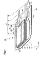
- FIG. 1 is a partly broken perspective view showing the electric double layer capacitor in accordance with an embodiment
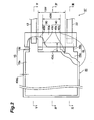
- Fig. 2 is a partly broken plan view of the multilayer structure in the lithium-ion secondary battery of Fig. 1;
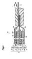
- Fig. 3 is a schematic sectional view of the multilayer structure taken along the line III ⁇ III of Fig. 2;
- Fig. 4 is a schematic sectional view of the multilayer structure taken along the line IV ⁇ IV of Fig. 2;
- Fig. 5 is a schematic sectional view of the multilayer structure taken along the line V-V of Fig. 2;
- Fig. 6 is a sectional view showing a step of manufacturing the electric double layer capacitor of Fig. 1;
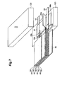
- Fig. 7 is a perspective view showing a step of manufacturing the electric double layer capacitor of Fig. 1 subsequent to Fig. 6;
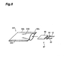
- Fig. 8 is a perspective view showing a step of manufacturing the electric double layer capacitor of Fig. 1 subsequent to Fig. 7;
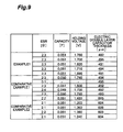
- Fig. 9 is a table showing characteristics of the electric double layer capacitors in accordance with Example 1 and Comparative Examples 1 and 2.
- Fig. 1 is a partly broken perspective view showing the electric double layer capacitor 100 in accordance with a first embodiment of the present invention.
- Fig. 2 is a plan view of the multilayer structure 87 of Fig. 1.
- Fig. 3 is a sectional view of the multilayer structure 87 taken along the line III ⁇ III of Fig. 2.
- Fig. 4 is a sectional view of the multilayer structure 87 taken along the line IV ⁇ IV of Fig. 2.
- Fig. 5 is a sectional view of the multilayer structure 87 taken along the line V ⁇ V of Fig. 2.
- the electric double layer capacitor 100 in accordance with this embodiment is mainly constructed by a multilayer body 85, a case (outer casing) 50 containing the multilayer body 85 in a closed state, leads 12 and 22 for connecting the multilayer body 85 to the outside of the case 50, and a fixing member 90 for securing the multilayer body 85.
- the multilayer body 85, fixing member 90, and leads 12 and 22 constitute the multilayer structure 87.
- a collector plate 15, an active material layer 10, a separator 40, an active material layer 10, a collector plate 16, an active material layer 10, a separator 40, an active material layer 10, a collector plate 15, an active material layer 10, a separator 40, an active material layer 10, a collector plate 16, an active material layer 10, a separator 40, an active material layer 10, and a collector plate 15 are successively laminated from the upper side.
- each collector plate 15 has a rectangular main part 15a and a tab part 15b which is connected to the main part 15a and smaller than the main part 15a.
- each collector plate 16 has a rectangular main part 16a and a tab part 16b which is connected to the main part 16a and smaller than the main part 16a.
- the collector plates 15, 16 are alternately stacked such that the respective main parts 15a, 16a of the collector plates 15, 16 oppose each other while the tab parts 15b, 16b of the collector plates 15, 16 align in two respective rows. Namely, when the multilayer body 85 is seen in the laminating direction as shown in Fig. 2, the tab parts 15b are stacked in one row, and the tab parts 16b are stacked in one row.
- Materials for the collector plates 15, 16 are not restricted in particular as long as they are metal materials usually employed as collector plates for active material layers in electric double layer capacitors. Their examples include copper, nickel, and aluminum.
- the active material layers 10 are formed on the respective surfaces of the main parts 15a, 16a of the collector plates 15, 16, and are attached to their corresponding collector plates 15, 16.
- the active material layers 10 are also in contact with the surfaces of the separators 40.
- Each active material layer 10 is a layer containing an active material, a conductive auxiliary agent, a binder, and the like.
- the active material is not restricted in particular, whereby materials which can construct polarizable electrodes such as carbon electrodes employed in known electric double layer capacitors can be used.
- carbon materials e.g., activated carbon
- coking coke e.g., petroleum coke manufactured by a delayed coker from material oils such as bottom oils of fluidized catalytic crackers for petroleum-based heavy oils and residual oils of vacuum distillers
- coking coke e.g., petroleum coke manufactured by a delayed coker from material oils such as bottom oils of fluidized catalytic crackers for petroleum-based heavy oils and residual oils of vacuum distillers
- the conductive auxiliary agent is not restricted in particular as long as it ameliorates the conductivity of the active material layer 10, whereby known conductive auxiliary agents can be used. Its examples include carbon materials such as carbon blacks and powder graphite, fine powders of metals such as aluminum and stainless steel, and mixtures of the carbon materials and fine powders of metals.
- the binder is not restricted in particular as long as it can connect particles of the active material and conductive auxiliary agent together and bind them as an active material layer to the collector plates 16, whereby known binders can be used.
- the binder include polyvinylidene fluoride (PVDF), polytetrafluoroethylene (PTFE), polyethylene (PE), polypropylene (PP), and fluorine rubber.
- Each separator 40 is arranged between the active material layers 10, 10 formed on the respective collector plates 15, 16. As shown in Figs. 2 to 5, the end faces of the separators 40 project out of the end faces of the active material layers 10 and the main parts 15a, 16a of the collector plates 15, 16. Specifically, as shown in Fig. 2, each separator 40 has a main part 40a, a shorter tab part 40b, and a longer tab part 40c.
- the main part 40a is arranged between the respective active material layers 10, 10 of the collector plates 15, 16, and has the same area and form as those of each active material layer 10.
- the shorter tab part 40b is provided along the outer periphery of the main part 40a, and protrudes outward by the length of 40bL from between the main parts 15a, 16a of the collector plates 15, 16 as shown in Figs. 2 to 5.
- the shorter tab part 40b reduces the short circuit between the active material layers 10, 10 holding the separator 40 therebetween.
- the longer tab part 40c is provided on the outside of the main part 40a, and projects to the gap between the respective rows of the tab parts 15b, 16b of the collector plates 15, 16.
- the longer tab part 40c projects by the length of 40cL from between the main parts 15a, 16a of the collector plates 15, 16.
- the length 40cL of the longer tab part 40c is longer than the length 40bL of the shorter tab part 40b.
- the width 40W of the longer tab part 40c is smaller than the gap 15W between the respective rows of the tab parts 15b, 16b of the collector plates 15, 16.
- the material for the separators 40 is not limited in particular as long as it is an electrically insulating porous body, whereby separators employed in known electric double layer capacitors can be used.
- the electrically insulating porous bodies include multilayer bodies of films constructed by polyethylene, polypropylene, or polyolefin, extended films of mixtures of these resins, and nonwoven fabrics of fibers constructed by at least one kind of constituent material selected from the group consisting of cellulose, polyester, polyacrylonitrile, and polypropylene.
- the electrolyte is contained in the active material layers 10 and within pores of the separators 40.
- the electrolyte is not restricted in particular, whereby electrolytes employed in known electric double layer capacitors (aqueous electrolytic solutions and nonaqueous electrolytic solutions using organic solvents) can be used.
- electrolytes using organic solvents nonaqueous electrolytes
- As the electrolyte one in which an ammonium salt is dissolved in a nonaqueous solvent (organic solvent) is preferably used.
- the kind of electrolyte solution is chosen in view of the solubility and degree of dissociation of the solute and the viscosity of the liquid in general, and is desirably an electrolyte solution having a high conductivity and a high potential window (high decomposition starting voltage).
- a solution of a quaternary ammonium salt such as tetraethylammonium tetrafluoroborate (TEA) in an organic solvent such as propylene carbonate, diethylene carbonate, or acetonitrile is used. In this case, moisture contamination must be controlled strictly.
- the electrolyte may be not only a liquid one but also a gelled electrolyte obtained by adding a gelling agent thereto.
- a solid electrolyte an electrolyte constituted by a solid polymer electrolyte or ionically conductive inorganic material
- a solid electrolyte an electrolyte constituted by a solid polymer electrolyte or ionically conductive inorganic material
- one separator 40, a pair of active material layers 10, 10 holding the separator therebetween, and the electrolyte constitute a unit capacitor cp.
- the leads 12, 22 each having a ribbon-like outer form project from within the case 50 to the outside through a seal part 50b.
- the leads 12, 22 are formed from a conductor material such as a metal. Aluminum is desirably used as the conductor material.
- the end part of the lead 12 within the case 50 is connected to respective end parts of the tab parts 15b of the collector plates 15 by resistance welding or the like, whereby, the lead 12 is electrically connected to the active material layers 10 through the collector plates 15.
- the end part of the lead 22 within the case 50 is connected to respective end parts of the tab parts 16b of the collector plates 16 by resistance welding or the like, whereby the lead 22 is electrically connected to the active material layers 10 through the collector plates 16.
- the leads 12 and 22 are separated from each other in a direction orthogonal to the laminating direction of the multilayer body 85.
- the fixing member 90 is one in which rectangular sheets 90a, 90b are stacked in the laminating direction of the collector plates 15, 16 and fused together by heating. As shown in Figs. 1 to 5, the fixing member 90 holds the end part of the lead 12 on the multilayer body side, the tab parts 15b of the collector plates 15 stacked with respect to the lead 12, the end part of the lead 22 on the multilayer body side, the tab parts 16b of the collector plates 16 stacked with respect to the lead 22, and the longer tab parts 40c of the separators 40 between the sheets 90a, 90b.
- the fixing member 90 is bonded to the tab parts 16b, longer tab parts 40c, and tab parts 15b, and secures them to each other.
- the fixing member 90 also covers the parts of leads 12 and 22 on the tab part side.
- the material for the fixing member 90 is not limited in particular as long as it is an insulator, but is preferably formed from a synthetic resin.
- the fixing member 90 is preferably made of a thermoplastic resin in particular because of its easiness in bonding to the tab parts 15b, 16b and longer tab parts 40c.
- Acid-denatured polyolefins such as acid-denatured polypropylene and acid-denatured polyethylene are preferred in particular because of their high adhesion to metals.
- the case 50 is not limited in particular as long as it can seal the multilayer body 85 and prevent the air and moisture from entering the case, whereby cases employed in known electric double layer capacitors can be used.
- a metal sheet such as aluminum whose inner and outer faces are respectively laminated with a thermoplastic resin such as PP and a resin such as PET can be used.
- the case 50 is formed by folding a rectangular flexible sheet 51C into two parts at a substantially longitudinal center part, whereby the multilayer body 85 is held from both sides of the laminating direction (vertical direction).
- the seal parts 50b in three sides other than the fold part 50a are bonded by heat sealing or with an adhesive, whereby the multilayer body 85 is sealed therein.
- the case 50 holds the fixing member 90 at the seal parts 50b, so as to be bonded thereto.
- the coating liquid for the active material layers is a liquid in which the above-mentioned active material, conductive auxiliary agent, binder, and the like are dispersed in a solvent.
- the solvent employed in the coating liquid is not limited in particular as long as it can dissolve the binder and disperse the active material and conductive auxiliary agent.
- N-methyl-2-pyrrolidone, N,N-dimethylformamide, or the like can be employed when PVdF is used for the binder, for example.
- sheets such as aluminum and etching aluminum foils for collector plates are prepared.
- the coating liquid is applied onto one face of each sheet for the collector plate and then is dried, so as to form an active material layer.
- product is cut out into forms each having a main part 15a and a tab part 15b, whereby two double layer electrodes 120 each having the active material layer 10 formed on one face of the main part 15a as shown in Fig. 6 are obtained.
- the coating liquid is applied to both faces of a collector plate sheet and then is dried, so as to form active material layers on both faces.
- the technique for applying the coating liquid to the collector plates is not limited in particular and can appropriately be determined according to the material, form, and the like of the sheets for collector plates. Examples of the technique include metal mask printing, electrostatic deposition, dip coating, spray coating, roll coating, doctor blading, gravure coating, and screen printing. Thus coated layers are extended by a platen press, calender rolls, or the like if necessary. Both faces of the tab parts 15b, 16b are free of the active material layers 10.
- separators each having a main part 40a, a shorter tab part 40b, and a longer tab part 40c are prepared. Specifically, the separators are made by cutting out an insulating porous material into a predetermined size and form.
- the double layer electrodes 120, three-layer electrode 130, and three-layer electrodes 140 are laminated so as to alternate with the separators 40 in the order of Fig. 6, i.e., in the order of the double layer electrode 120, separator 40, three-layer electrode 140, separator 40, three-layer electrode 130, separator 40, three-layer electrode 140, separator 40, and double layer electrode 120, so as to yield a multilayer body 85 as shown in Fig. 7.
- each separator 40 is arranged such that the respective active material layers 10 are in contact with both sides thereof.
- the tab parts 15b are aligned in one row
- the tab parts 16b are aligned in one row at positions different from the tab parts 15b
- the longer tab parts 40c of the separators 40 are arranged between the rows of the tab parts 15b, 16b.
- end parts of the tab parts 15b are stacked and welded to an end part of a lead 12
- end parts of the tab parts 16b are stacked and welded to an end part of a lead 22.
- sheets 90a, 90b are prepared.
- the tab parts 15b, the tab part side of the lead 12, the longer tab parts 40c, the tab parts 16b, and the tab part side of the lead 22 are held with the sheets 90a, 90b from both sides, and the sheets 90a, 90b are thermally fused with heat sealers 125, 125, so as to unite the sheets 90a, 90b together and bond them to the tab parts, thereby forming the fixing member 90.
- a rectangular sheet formed by laminating both faces of an aluminum foil with a resin is folded into two parts, and seal parts 50b of two sides other than an opening 50c is heat-sealed with the heat sealers, so as to form a case 50f.
- the multilayer structure 87 is inserted into the case 50 from the opening 50c in the remaining one side.
- the electrolyte is injected into the case 50f in a vacuum container, so that the multilayer body 85 is dipped into the electrolyte.
- each of the leads 12, 22 is projected out from within the case 50f, and the opening 50c of the case 50f is sealed with the heat sealers while in a state where the fixing member 90 is held in the opening 50c. This completes the making of the electric double layer capacitor 100.
- the fixing member 90 secures the tab parts 15b, 16b of the collector plates 15, 16 to the longer tab parts 40c of the separators 40, whereby the separators 40 and the collector plates 15, 16 are secured to each other.
- the fixing member 90 secures the tab parts 15b, 16b of the collector plates 15, 16 to the longer tab parts 40c of the separators 40. Therefore, the fixing member 90 does not decrease the area of interfaces between the active material layers 10 and separators 40, and is less likely to inhibit ions from migrating and so forth in the electrolyte, whereby the internal resistance of the electric double layer capacitor 100 can be lowered. Moreover, configured fixing member 90 is hard to affect the thickness of the multilayer body or electrochemical device, and thus can contribute to thinning the electric double layer capacitor 100.
- the tab parts 15b, 16b alternate with each other in two rows, whereas the longer tab parts 40c of the separators 40 project to the gap between the respective rows of the tab parts 15b, 16b. Since the fixing member 90 secures thus arranged tab parts 15b, 16b and longer tab parts 40c, the size of the fixing member 90 becomes relatively small, which is favorable.
- the fixing member 90 has such a form and size that it does not overlap the main parts 15a, 16a of the collector plates 15, 16 when the electric double layer capacitor 100 is viewed in a direction perpendicular to the collector plates 15 and the like. This is favorable in that the fixing member 90 does not hinder the main parts 15a, 16a of the collector plates 15, 16 from being heat-pressed from the outside of the case 50 after the multilayer body 85 is sealed into the case 50.
- the width 40W of the longer tab parts 40c is shorter than the gap 15W between the respective rows of the tab parts 15b, 16b, the protruded parts 40c of the separators 40 are not held between the upper and lower tab parts in each of the rows of the tab parts 15b, 16b. Therefore, even when the length of projection 40cL of the tab parts 15b, 16b is made shorter, the tab parts 15b, 16b are electrically connected in the respective rows, and thus can easily be connected to their corresponding leads 12, 22.
- the fixing member 90 is bonded to the tab parts 15b, 16b of the collector plates 15, 16 and to the longer tab parts 40c of the separators 40, whereby they are secured to each other. Therefore, a small fixing member enables reliable fixing.
- the fixing member 90 is made of a thermoplastic resin and thus can easily be bonded to the tab parts 15b, 16b and longer tab parts 40c by thermal fusion.
- the fixing member 90 is one in which two sheets 90a, 90b opposing each other in the laminating direction of the collector plates 15, 16 are bonded to each other, while the respective tab parts 15b, 16b of the collector plates 15, 16 and the longer tab parts 40c of the separators 40 are held between the sheets 90a, 90b, the fixing operation is easy.
- the leads 12, 22 are connected to their corresponding tab parts 15b, 16b, whereas the fixing member 90 further covers the leads 12, 22.
- the fixing member 90 can also act as a cover made of a resin or the like for improving the airtightness between the case 50 and leads 12, 22, which is favorable in terms of economy.
- the fixing member 90 secures the longer tab parts 40c of the separators 40 to the tab parts 15b, 16b of the collector plates 15, 16 in the above-mentioned embodiment
- the shorter tab parts 40b of the separators 40 may be secured to the tab parts 15b, 16b of the collector plates 15, 16.
- the fixing member 90 covers the leads 12, 22 in the above-mentioned embodiment, the present invention can be realized even when the leads 12, 22 are not covered.
- the fixing member 90 may connect the longer tab parts 40c to the tab parts 15b, 16b.
- a highly airtight seal can be obtained by cladding the leads 12, 22 with a cover made of a resin or the like different from the fixing member and then thermally bonding this cover to the case.
- the tab parts 15b, 16b are arranged in alternate rows in the above-mentioned embodiment.
- the total number of collector plates is 2 or the like, a mode in which the tab parts 15b, 16b oppose each other while holding therebetween a longer tab part 40c of a separator can also be realized.
- the above-mentioned embodiment comprises four unit capacitors cp
- the number of unit capacitors cp may be more than 4, or 3 or less, e.g., 1.
- the collector plates 15, 16 have such forms that the fixing member 90 does not overlap the collector plates 15, 16 when viewed in the laminating direction of the collector plates 15, 16, the present invention can also be realized even when they overlap each other.
- the present invention can also be realized when a fixing member such as clip holds the tab parts 15b, 16b and longer tab parts 40c together so as to secure the tab parts 15b, 16b and longer tab parts 40c, for example.
- the present invention is not limited to the electric double layer capacitor, but is also employable in capacitors such as pseudocapacitors and redox capacitors, for example.
- the present invention is also employable in batteries such as lithium-ion secondary batteries without being restricted to capacitors.
- batteries such as lithium-ion secondary batteries
- the active material layer on one side of a separator is a negative electrode active material layer
- the active material layer on the other side of the separator is a positive electrode active material layer.
- An example of the negative electrode active material is a carbon material having a graphite structure.
- An example of the electrolyte is a nonaqueous electrolyte containing a salt including a lithium ion.
- a double layer electrode including a collector plate having a tab part and a main part with an active material layer formed on one face of the main part, and a three-layer electrode including a tab part and a main part with active material layers formed on both faces of the main part.
- the thickness of the double layer electrode including the main part and active material layer was 45 ⁇ m, whereas the thickness of the three-layer electrode including the main part and two active material layers was 70 ⁇ m.
- the size of each main part was 7.80 x 7.80 mm, whereas the size of each tab part was 2.0 x 2.0 mm.
- an electrolyte sheet made of regenerated cellulose having a thickness of 30 ⁇ m was punched out so as to have a rectangular area (corresponding to a main part and a shorter tab part) of 8.2 x 8.2 mm and a longer tab part of 2.0 x 2.5 mm, thus yielding a separator.
- the electrodes and separators were arranged such that the tab parts of the collector plates were alternately arranged in two rows, and the tab parts of the separators were placed between the rows of the tab parts.
- a case was prepared by folding an aluminum laminate film having a thickness of 85 ⁇ m into two parts.
- the multilayer structure was held in this case, and two sides of an entrance part of the case were heat-sealed such that the fixing member was held by the aluminum laminate film.
- the case was dried for 12 hours in a vacuum dryer at 160°C, and then, with a polycarbonate solution containing 1.0 mol/L of TEA-BF 4 added thereto, the remaining side was heat-sealed under reduced pressure.
- the main part of the multilayer body was pressed at a pressure of 4.9 x 10 4 Pa from the outside of the case by a platen press heated at 80°C.
- the final thickness of the electric double layer capacitor was about 490 ⁇ m.
- An electric double layer capacitor was obtained as in Example 1 except that heat sealing was effected in a state without holding the longer tab parts of the separators between the two sheets when forming the fixing member.
- An electric double layer capacitor was obtained as in Example 1 except that one round of an adhesive tape made of polyimide having a thickness of 65 ⁇ m was wound about the outer periphery of the multilayer body before forming the fixing member after laminating the multilayer body.
- Example 1 In Example 1 in which the fixing member secured the tab parts of the collector plates to the longer tab parts of the separators, the equivalent series resistance corresponding to the internal resistance was sufficiently low, the capacity was uniform, the holding voltage was sufficient, and the thickness was sufficiently small.
Landscapes
- Engineering & Computer Science (AREA)
- Power Engineering (AREA)
- Microelectronics & Electronic Packaging (AREA)
- Manufacturing & Machinery (AREA)
- Chemical & Material Sciences (AREA)
- Chemical Kinetics & Catalysis (AREA)
- Electrochemistry (AREA)
- General Chemical & Material Sciences (AREA)
- Electric Double-Layer Capacitors Or The Like (AREA)
- Secondary Cells (AREA)
- Cell Separators (AREA)
- Connection Of Batteries Or Terminals (AREA)
Abstract
Description
- The present invention relates to an electrochemical device.
- Electrochemical devices such as lithium-ion secondary batteries and electric double layer capacitors often include a multilayer body in which separators and collector plates each having an active material layer are repeatedly laminated. For manufacturing such an electrochemical device, it is necessary for the collector plates and separators to be secured to each other in order to improve the handling of the multilayer body.
- The separators and collector plates have conventionally been secured to each other by laminating the separators and collector plates after coating their surfaces with a bonding resin, or wrapping the outer periphery of the laminate of separators and collector plates with one round of an adhesive tape. (See
Japanese Patent Application Laid-Open No. 2000-252175 - When a surface of an active material layer or separator is coated with a bonding resin or the like, however, ions of the electrolyte are inhibited from migrating and so forth in this part, whereby rises in internal resistance and the like occur. On the other hand, wrapping the outside of the multilayer body with the adhesive tape increases the thickness of the multilayer body, thereby contradicting the demand for thinning the electrochemical device.
- In view of the problem mentioned above, it is an object of the present invention to provide an electrochemical device which can be made thinner and keep internal resistance from increasing while having a multilayer body which is easy to handle.
- The electrochemical device in accordance with the present invention comprises a pair of collector plates, a separator, an active material layer, an electrolyte, and a fixing member.
- The pair of collector plates each have a main part and a tab part and are arranged such that the main parts thereof oppose each other.
- The separator has a main part and a tab part, and is arranged such that the main part thereof is disposed between the main parts of the pair of collector plates while the tab part of the separator projects out from between the main parts of the pair of collector plates.
- The active material layer is formed on the main part of each collector plate and is in contact with the separator.
- The electrolyte is in contact with each active material layer.
- The fixing member is insulative and secures the tab part of each collector plate and the tab part of the separator to each other.
- In the present invention, the fixing member secures the separator and each collector plate to each other. This makes it easier to handle the multilayer body including the separator and collector plates at the time of manufacture.
- The fixing member secures the tab parts of the collector plates to the tab part of the separator. Therefore, the fixing member does not reduce the area of interfaces between the active material layers and separator, so that ions in the electrolyte are less likely to be inhibited from migrating and so forth, whereby the electrochemical device can lower its internal resistance. Thus configured fixing member is hard to affect the thickness of the multilayer body or electrochemical device, and thus can contribute to thinning the electrochemical device.
- Preferably, the fixing member has a form kept from overlapping the main parts of the collector plates when the electrochemical device is viewed in the laminating direction of the collector plates.
- In this case, the multilayer body in which the collector plates, active material layers, and separator are laminated can easily be subjected to a process of heat-pressing the main parts of the collector plates in the laminating direction. Such heat pressing contributes to suppressing the internal resistance, since unnecessary spaces are less likely to occur between the active material layers and separator.
- Preferably, the fixing member is bonded to the tab part of each collector plate and the tab part of the separator. When the fixing member is bonded to these tab parts, the tab parts are secured to each other, whereby even a small fixing member can reliably secure the tag parts.
- Preferably, in this case, the fixing member is made of a thermoplastic resin. This makes it easy for the fixing member to be bonded to the tab parts of the collector plates and the tab part of the separator by thermal fusion.
- Preferably, leads are connected to the respective tab parts of the collector plates, and the fixing member further covers the leads.
- A multilayer body including collector plates having leads connected to tab parts, active material layers, and a separator are often sealed into a case. Here, the surface of a lead may be clad with a cover made of a resin or the like so as to improve the airtightness between the case and the lead before bonding the cover and the case to each other. In the present invention, the fixing member further covers the lead and thus can also act as the cover for the lead, which is favorable in terms of economy.
- Preferably, the fixing member comprises two sheets, bonded to each other, opposing each other in the laminating direction of the collector plates, while holding the tab parts of the pair of collector plates and the tab part of the separator between the sheets. Such a fixing member is easy to perform a fixing operation.
- Preferably, at least three collector plates are provided; the collector plates are stacked such that the main parts thereof oppose each other while the respective tab parts thereof are alternately aligned in two rows; separators are arranged such that the main parts thereof are placed between the main parts of the collector plates while the tab parts of the separators project out from between the main parts of the collector plates; respective active material layers are formed on the main parts of the collector plates; the tab parts of the separators project to a gap between the two rows of the tab parts of the collector plates; and the fixing member secures the tab parts of the collector plates and the tab parts of the separators to each other.
- This realizes an electrochemical device having a multilayer laminate structure. Since the tab parts of the collector plates align in two rows while the tab parts of the separators are arranged between the two rows of the tab parts of the collector plates, a small fixing member can secure the tab parts of the collector plates and the tab parts of the separators to each other.
- Here, it will be preferred if the tab parts of the separators have a width smaller than the gap between the two rows of the tab parts of the collector plates.
- When the tab parts of the separators have a width smaller than the gap between the two rows of the tab parts of the collector plates, the tab parts of the separators are not held between the vertically stacked tab parts of the collector plates in each row. Therefore, even when the tab parts of the collector plates are made shorter, the upper and lower tab parts of the collector plates in each row can electrically be connected to each other. This facilitates connections with leads, and is extremely suitable for an electrochemical device in which unit cells are connected in parallel.
- The present invention can provide an electrochemical device which can be made thinner and keep internal resistance from increasing while having a multilayer body which is easy to handle.
- [Fig. 1] Fig. 1 is a partly broken perspective view showing the electric double layer capacitor in accordance with an embodiment;
- [Fig. 2]Fig. 2 is a partly broken plan view of the multilayer structure in the lithium-ion secondary battery of Fig. 1;
- [Fig. 3]Fig. 3 is a schematic sectional view of the multilayer structure taken along the line III―III of Fig. 2;
- [Fig. 4]Fig. 4 is a schematic sectional view of the multilayer structure taken along the line IV―IV of Fig. 2;
- [Fig. 5]Fig. 5 is a schematic sectional view of the multilayer structure taken along the line V-V of Fig. 2;
- [Fig. 6]Fig. 6 is a sectional view showing a step of manufacturing the electric double layer capacitor of Fig. 1;
- [Fig. 7]Fig. 7 is a perspective view showing a step of manufacturing the electric double layer capacitor of Fig. 1 subsequent to Fig. 6;
- [Fig. 8]Fig. 8 is a perspective view showing a step of manufacturing the electric double layer capacitor of Fig. 1 subsequent to Fig. 7; and
- [Fig. 9]Fig. 9 is a table showing characteristics of the electric double layer capacitors in accordance with Example 1 and Comparative Examples 1 and 2.
- First Embodiment
- To begin with, an embodiment of the electric double layer capacitor (electrochemical device) in accordance with the present invention will be explained in detail.
- Fig. 1 is a partly broken perspective view showing the electric
double layer capacitor 100 in accordance with a first embodiment of the present invention. Fig. 2 is a plan view of themultilayer structure 87 of Fig. 1. Fig. 3 is a sectional view of themultilayer structure 87 taken along the line III―III of Fig. 2. Fig. 4 is a sectional view of themultilayer structure 87 taken along the line IV―IV of Fig. 2. Fig. 5 is a sectional view of themultilayer structure 87 taken along the line V― V of Fig. 2. - As shown in Figs. 1 to 5, the electric
double layer capacitor 100 in accordance with this embodiment is mainly constructed by amultilayer body 85, a case (outer casing) 50 containing themultilayer body 85 in a closed state, leads 12 and 22 for connecting themultilayer body 85 to the outside of thecase 50, and afixing member 90 for securing themultilayer body 85. Themultilayer body 85,fixing member 90, and leads 12 and 22 constitute themultilayer structure 87. - In the
multilayer body 85, as shown in Figs. 3 to 5, acollector plate 15, anactive material layer 10, aseparator 40, anactive material layer 10, acollector plate 16, anactive material layer 10, aseparator 40, anactive material layer 10, acollector plate 15, anactive material layer 10, aseparator 40, anactive material layer 10, acollector plate 16, anactive material layer 10, aseparator 40, anactive material layer 10, and acollector plate 15 are successively laminated from the upper side. - Collector Plate
- As shown in Figs. 1 and 2, each
collector plate 15 has a rectangularmain part 15a and atab part 15b which is connected to themain part 15a and smaller than themain part 15a. Similarly, as shown in Fig. 2, eachcollector plate 16 has a rectangularmain part 16a and atab part 16b which is connected to themain part 16a and smaller than themain part 16a. Thecollector plates main parts collector plates tab parts collector plates multilayer body 85 is seen in the laminating direction as shown in Fig. 2, thetab parts 15b are stacked in one row, and thetab parts 16b are stacked in one row. - Materials for the
collector plates - Active Material Layer
- As shown in Figs. 3 to 5, the active material layers 10 are formed on the respective surfaces of the
main parts collector plates corresponding collector plates separators 40. - Each
active material layer 10 is a layer containing an active material, a conductive auxiliary agent, a binder, and the like. The active material is not restricted in particular, whereby materials which can construct polarizable electrodes such as carbon electrodes employed in known electric double layer capacitors can be used. For example, carbon materials (e.g., activated carbon) obtained by activating coking coke (e.g., petroleum coke manufactured by a delayed coker from material oils such as bottom oils of fluidized catalytic crackers for petroleum-based heavy oils and residual oils of vacuum distillers) can be used as a main ingredient for a constituent material. - The conductive auxiliary agent is not restricted in particular as long as it ameliorates the conductivity of the
active material layer 10, whereby known conductive auxiliary agents can be used. Its examples include carbon materials such as carbon blacks and powder graphite, fine powders of metals such as aluminum and stainless steel, and mixtures of the carbon materials and fine powders of metals. - The binder is not restricted in particular as long as it can connect particles of the active material and conductive auxiliary agent together and bind them as an active material layer to the
collector plates 16, whereby known binders can be used. Examples of the binder include polyvinylidene fluoride (PVDF), polytetrafluoroethylene (PTFE), polyethylene (PE), polypropylene (PP), and fluorine rubber. - Separator
- Each
separator 40 is arranged between the active material layers 10, 10 formed on therespective collector plates separators 40 project out of the end faces of the active material layers 10 and themain parts collector plates separator 40 has amain part 40a, ashorter tab part 40b, and alonger tab part 40c. - The
main part 40a is arranged between the respective active material layers 10, 10 of thecollector plates active material layer 10. - The
shorter tab part 40b is provided along the outer periphery of themain part 40a, and protrudes outward by the length of 40bL from between themain parts collector plates shorter tab part 40b reduces the short circuit between the active material layers 10, 10 holding theseparator 40 therebetween. - The
longer tab part 40c is provided on the outside of themain part 40a, and projects to the gap between the respective rows of thetab parts collector plates longer tab part 40c projects by the length of 40cL from between themain parts collector plates longer tab part 40c is longer than the length 40bL of theshorter tab part 40b. - The
width 40W of thelonger tab part 40c is smaller than thegap 15W between the respective rows of thetab parts collector plates - The material for the
separators 40 is not limited in particular as long as it is an electrically insulating porous body, whereby separators employed in known electric double layer capacitors can be used. Examples of the electrically insulating porous bodies include multilayer bodies of films constructed by polyethylene, polypropylene, or polyolefin, extended films of mixtures of these resins, and nonwoven fabrics of fibers constructed by at least one kind of constituent material selected from the group consisting of cellulose, polyester, polyacrylonitrile, and polypropylene. - Electrolyte
- The electrolyte is contained in the active material layers 10 and within pores of the
separators 40. The electrolyte is not restricted in particular, whereby electrolytes employed in known electric double layer capacitors (aqueous electrolytic solutions and nonaqueous electrolytic solutions using organic solvents) can be used. Here, electrolytes using organic solvents (nonaqueous electrolytes) are preferred. As the electrolyte, one in which an ammonium salt is dissolved in a nonaqueous solvent (organic solvent) is preferably used. - Though not restricted in particular, the kind of electrolyte solution is chosen in view of the solubility and degree of dissociation of the solute and the viscosity of the liquid in general, and is desirably an electrolyte solution having a high conductivity and a high potential window (high decomposition starting voltage). As a typical example, a solution of a quaternary ammonium salt such as tetraethylammonium tetrafluoroborate (TEA) in an organic solvent such as propylene carbonate, diethylene carbonate, or acetonitrile is used. In this case, moisture contamination must be controlled strictly.
- In this embodiment, the electrolyte may be not only a liquid one but also a gelled electrolyte obtained by adding a gelling agent thereto. Instead of the electrolyte, a solid electrolyte (an electrolyte constituted by a solid polymer electrolyte or ionically conductive inorganic material) may be contained as well.
- As shown in Figs. 3 to 5, one
separator 40, a pair of active material layers 10, 10 holding the separator therebetween, and the electrolyte constitute a unit capacitor cp. - Lead
- As shown in Fig. 1, the
leads case 50 to the outside through aseal part 50b. - The leads 12, 22 are formed from a conductor material such as a metal. Aluminum is desirably used as the conductor material.
- The end part of the
lead 12 within thecase 50 is connected to respective end parts of thetab parts 15b of thecollector plates 15 by resistance welding or the like, whereby, thelead 12 is electrically connected to the active material layers 10 through thecollector plates 15. - On the other hand, as shown in Figs. 1 to 3, the end part of the
lead 22 within thecase 50 is connected to respective end parts of thetab parts 16b of thecollector plates 16 by resistance welding or the like, whereby thelead 22 is electrically connected to the active material layers 10 through thecollector plates 16. The leads 12 and 22 are separated from each other in a direction orthogonal to the laminating direction of themultilayer body 85. - Fixing Member
- As shown in Figs. 1 to 5, the fixing
member 90 is one in whichrectangular sheets collector plates member 90 holds the end part of thelead 12 on the multilayer body side, thetab parts 15b of thecollector plates 15 stacked with respect to thelead 12, the end part of thelead 22 on the multilayer body side, thetab parts 16b of thecollector plates 16 stacked with respect to thelead 22, and thelonger tab parts 40c of theseparators 40 between thesheets - Namely, the fixing
member 90 is bonded to thetab parts 16b,longer tab parts 40c, andtab parts 15b, and secures them to each other. The fixingmember 90 also covers the parts ofleads - The material for the fixing
member 90 is not limited in particular as long as it is an insulator, but is preferably formed from a synthetic resin. The fixingmember 90 is preferably made of a thermoplastic resin in particular because of its easiness in bonding to thetab parts longer tab parts 40c. Acid-denatured polyolefins such as acid-denatured polypropylene and acid-denatured polyethylene are preferred in particular because of their high adhesion to metals. - Case
- The
case 50 is not limited in particular as long as it can seal themultilayer body 85 and prevent the air and moisture from entering the case, whereby cases employed in known electric double layer capacitors can be used. For example, a metal sheet such as aluminum whose inner and outer faces are respectively laminated with a thermoplastic resin such as PP and a resin such as PET can be used. In this embodiment, as shown in Fig. 1, thecase 50 is formed by folding a rectangularflexible sheet 51C into two parts at a substantially longitudinal center part, whereby themultilayer body 85 is held from both sides of the laminating direction (vertical direction). In the end parts of the foldedsheet 51C, theseal parts 50b in three sides other than thefold part 50a are bonded by heat sealing or with an adhesive, whereby themultilayer body 85 is sealed therein. Thecase 50 holds the fixingmember 90 at theseal parts 50b, so as to be bonded thereto. - Manufacturing Method
- An example of method of making the electric
double layer capacitor 100 will now be explained. - First, a coating liquid (slurry) for forming active material layers 10 on collector plates is prepared. The coating liquid for the active material layers is a liquid in which the above-mentioned active material, conductive auxiliary agent, binder, and the like are dispersed in a solvent. The solvent employed in the coating liquid is not limited in particular as long as it can dissolve the binder and disperse the active material and conductive auxiliary agent. N-methyl-2-pyrrolidone, N,N-dimethylformamide, or the like can be employed when PVdF is used for the binder, for example.
- Next, sheets such as aluminum and etching aluminum foils for collector plates are prepared. The coating liquid is applied onto one face of each sheet for the collector plate and then is dried, so as to form an active material layer. Thereafter, thus obtained product is cut out into forms each having a
main part 15a and atab part 15b, whereby twodouble layer electrodes 120 each having theactive material layer 10 formed on one face of themain part 15a as shown in Fig. 6 are obtained. Similarly, the coating liquid is applied to both faces of a collector plate sheet and then is dried, so as to form active material layers on both faces. Thereafter, thus obtained product is cut out into a form having amain part 15a and atab part 15b, so as to yield a three-layer electrode 130 having active material layers 10 formed on both faces of the collector plate sheet as shown in Fig. 6. Similarly, two 3-layer electrodes 140 each having amain part 16a, atab part 16b, and active material layers 10 formed on both faces of themain part 16a are obtained. Here, the technique for applying the coating liquid to the collector plates is not limited in particular and can appropriately be determined according to the material, form, and the like of the sheets for collector plates. Examples of the technique include metal mask printing, electrostatic deposition, dip coating, spray coating, roll coating, doctor blading, gravure coating, and screen printing. Thus coated layers are extended by a platen press, calender rolls, or the like if necessary. Both faces of thetab parts - Subsequently, separators each having a
main part 40a, ashorter tab part 40b, and alonger tab part 40c are prepared. Specifically, the separators are made by cutting out an insulating porous material into a predetermined size and form. - Next, the
double layer electrodes 120, three-layer electrode 130, and three-layer electrodes 140 are laminated so as to alternate with theseparators 40 in the order of Fig. 6, i.e., in the order of thedouble layer electrode 120,separator 40, three-layer electrode 140,separator 40, three-layer electrode 130,separator 40, three-layer electrode 140,separator 40, anddouble layer electrode 120, so as to yield amultilayer body 85 as shown in Fig. 7. Here, eachseparator 40 is arranged such that the respective active material layers 10 are in contact with both sides thereof. Also, thetab parts 15b are aligned in one row, thetab parts 16b are aligned in one row at positions different from thetab parts 15b, and thelonger tab parts 40c of theseparators 40 are arranged between the rows of thetab parts - Then, as shown in Fig. 7, end parts of the
tab parts 15b are stacked and welded to an end part of a lead 12, and end parts of thetab parts 16b are stacked and welded to an end part of alead 22. - Subsequently,
sheets tab parts 15b, the tab part side of thelead 12, thelonger tab parts 40c, thetab parts 16b, and the tab part side of thelead 22 are held with thesheets sheets heat sealers sheets member 90. - This completes a
multilayer structure 87 having themultilayer body 85, fixingmember 90, and leads 12 and 22 as shown in Fig. 8. - Subsequently, as shown in Fig. 8, a rectangular sheet formed by laminating both faces of an aluminum foil with a resin is folded into two parts, and seal
parts 50b of two sides other than anopening 50c is heat-sealed with the heat sealers, so as to form acase 50f. - Then, the
multilayer structure 87 is inserted into thecase 50 from theopening 50c in the remaining one side. Subsequently, the electrolyte is injected into thecase 50f in a vacuum container, so that themultilayer body 85 is dipped into the electrolyte. Thereafter, each of theleads case 50f, and theopening 50c of thecase 50f is sealed with the heat sealers while in a state where the fixingmember 90 is held in theopening 50c. This completes the making of the electricdouble layer capacitor 100. - Effects
- In such an electric
double layer capacitor 100, the fixingmember 90 secures thetab parts collector plates longer tab parts 40c of theseparators 40, whereby theseparators 40 and thecollector plates multilayer body 85 including theseparators 40 andcollector plates multilayer body 85 into thecase 50 and then sealing thecase 50 or the like, thecollector plates separator 40 are less likely to be misaligned and so forth in themultilayer body 85, whereby defects such as short circuits between the collector plates are restrained from occurring. - The fixing
member 90 secures thetab parts collector plates longer tab parts 40c of theseparators 40. Therefore, the fixingmember 90 does not decrease the area of interfaces between the active material layers 10 andseparators 40, and is less likely to inhibit ions from migrating and so forth in the electrolyte, whereby the internal resistance of the electricdouble layer capacitor 100 can be lowered. Moreover, configured fixingmember 90 is hard to affect the thickness of the multilayer body or electrochemical device, and thus can contribute to thinning the electricdouble layer capacitor 100. - The
tab parts longer tab parts 40c of theseparators 40 project to the gap between the respective rows of thetab parts member 90 secures thus arrangedtab parts longer tab parts 40c, the size of the fixingmember 90 becomes relatively small, which is favorable. - The fixing
member 90 has such a form and size that it does not overlap themain parts collector plates double layer capacitor 100 is viewed in a direction perpendicular to thecollector plates 15 and the like. This is favorable in that the fixingmember 90 does not hinder themain parts collector plates case 50 after themultilayer body 85 is sealed into thecase 50. - Since the
width 40W of thelonger tab parts 40c is shorter than thegap 15W between the respective rows of thetab parts parts 40c of theseparators 40 are not held between the upper and lower tab parts in each of the rows of thetab parts tab parts tab parts corresponding leads - The fixing
member 90 is bonded to thetab parts collector plates longer tab parts 40c of theseparators 40, whereby they are secured to each other. Therefore, a small fixing member enables reliable fixing. - The fixing
member 90 is made of a thermoplastic resin and thus can easily be bonded to thetab parts longer tab parts 40c by thermal fusion. - Since the fixing
member 90 is one in which twosheets collector plates respective tab parts collector plates longer tab parts 40c of theseparators 40 are held between thesheets - The leads 12, 22 are connected to their
corresponding tab parts member 90 further covers theleads multilayer structure 87 into thecase 50, thecase 50 is thermally fused so as to hold the fixingmember 90. Consequently, the fixingmember 90 can also act as a cover made of a resin or the like for improving the airtightness between thecase 50 and leads 12, 22, which is favorable in terms of economy. - Without being restricted to the above-mentioned embodiment, the present invention can be modified in various modes.
- For example, though the fixing
member 90 secures thelonger tab parts 40c of theseparators 40 to thetab parts collector plates shorter tab parts 40b of theseparators 40 may be secured to thetab parts collector plates - Though the fixing
member 90 covers theleads tab parts member 90 may connect thelonger tab parts 40c to thetab parts member 90 does not cover theleads leads - The
tab parts tab parts longer tab part 40c of a separator can also be realized. - Though the above-mentioned embodiment comprises four unit capacitors cp, the number of unit capacitors cp may be more than 4, or 3 or less, e.g., 1.
- Though the
collector plates member 90 does not overlap thecollector plates collector plates - Though the above-mentioned embodiment secures the
tab parts longer tab parts 40c to each other by bonding the fixingmember 90 to thetab parts longer tab parts 40c, the present invention can also be realized when a fixing member such as clip holds thetab parts longer tab parts 40c together so as to secure thetab parts longer tab parts 40c, for example. - Though the above-mentioned embodiment relates to an electric double layer capacitor, the present invention is not limited to the electric double layer capacitor, but is also employable in capacitors such as pseudocapacitors and redox capacitors, for example.
- The present invention is also employable in batteries such as lithium-ion secondary batteries without being restricted to capacitors. In the case of a lithium-ion secondary battery, for example, the active material layer on one side of a separator is a negative electrode active material layer, whereas the active material layer on the other side of the separator is a positive electrode active material layer. An example of the negative electrode active material is a carbon material having a graphite structure. Examples of the positive electrode active material include mixed metal oxides such as lithium cobaltate (LiCoO2), lithium nickelate (LiNiO2) lithium manganese spinel (LiMn2O4), those represented by a general formula of LiNixCoyMn2O2 (x + y + z = 1), lithium vanadium compound (LiV2O5), olivine-type LiMPO4 (where M is Co, Ni, Mn, or Fe), and lithium titanate (Li4Ti5O12). An example of the electrolyte is a nonaqueous electrolyte containing a salt including a lithium ion.
- The present invention will now be explained in detail with reference to an example and comparative examples, but will not be restricted to the example at all.
- Example 1
- To begin with, an active material coating material was made with a weight composition of activated carbon/carbon black (conductive auxiliary agent)/PVdF (binder) = 87/3/10, and was applied onto an etching aluminum foil having a thickness of 20 µm, so as to form a coated part in a portion thereof. After drying the coating, roll pressing was effected, so as to make a double layer electrode sheet having a structure of collector plate/active material layer, and a three-layer structure of active material layer/collector plate/active material layer. Subsequently, these sheets were punched out with dies, so as to form a double layer electrode including a collector plate having a tab part and a main part with an active material layer formed on one face of the main part, and a three-layer electrode including a tab part and a main part with active material layers formed on both faces of the main part. The thickness of the double layer electrode including the main part and active material layer was 45 µm, whereas the thickness of the three-layer electrode including the main part and two active material layers was 70 µm. The size of each main part was 7.80 x 7.80 mm, whereas the size of each tab part was 2.0 x 2.0 mm.
- Subsequently, an electrolyte sheet made of regenerated cellulose having a thickness of 30 µm was punched out so as to have a rectangular area (corresponding to a main part and a shorter tab part) of 8.2 x 8.2 mm and a longer tab part of 2.0 x 2.5 mm, thus yielding a separator.
- Then, they were laminated so as to yield a structure of double layer electrode / separator / three-layer electrode / separator / three-layer electrode / separator / double layer electrode, thereby forming a multilayer body. Here, the electrodes and separators were arranged such that the tab parts of the collector plates were alternately arranged in two rows, and the tab parts of the separators were placed between the rows of the tab parts. :
- Thereafter, the tab part group of electrodes on one side was ultrasonically fused to one lead, whereas the tab part group of electrodes on the other side was ultrasonically fused to the other lead. Subsequently, two acid-denatured propylene films (each having a thickness of 30 µm, a width of 3.0 mm, and a length of 10.0 mm) adapted to bond a metal and a resin to each other were prepared, and were arranged such as to hold therebetween the tab part group on one side, the tab part group on the other side, their corresponding leads, and the respective longer tab parts of the separators in the laminating direction. Then, the two films were sealed with heat sealers, so as to be bonded together, thus forming a fixing member. Here, 0.2-mm portions in the tab parts of the separators were held with the fixing member. This yielded a multilayer structure. Heat sealing was effected by applying a pressure of 10 x 104 Pa at a temperature of 175°C for 15 seconds. The acid-denatured polypropylene films did not overlap the main parts of the electrodes and the main parts of the separators.
- A case was prepared by folding an aluminum laminate film having a thickness of 85 µm into two parts. The multilayer structure was held in this case, and two sides of an entrance part of the case were heat-sealed such that the fixing member was held by the aluminum laminate film. Thereafter, the case was dried for 12 hours in a vacuum dryer at 160°C, and then, with a polycarbonate solution containing 1.0 mol/L of TEA-BF4 added thereto, the remaining side was heat-sealed under reduced pressure. Thereafter, the main part of the multilayer body was pressed at a pressure of 4.9 x 10⁴ Pa from the outside of the case by a platen press heated at 80°C. The final thickness of the electric double layer capacitor was about 490 µm.
- Comparative Example 1
- An electric double layer capacitor was obtained as in Example 1 except that heat sealing was effected in a state without holding the longer tab parts of the separators between the two sheets when forming the fixing member.
- Comparative Example 2
- An electric double layer capacitor was obtained as in Example 1 except that one round of an adhesive tape made of polyimide having a thickness of 65 µm was wound about the outer periphery of the multilayer body before forming the fixing member after laminating the multilayer body.
- In each of the example and comparative examples, five electric double layer capacitors were obtained by the same method.
- In each of the example and comparative examples, after a voltage of 2.7 V was applied for 6 hr in an environment at 70°C, the electric double layer capacitors were discharged to 0 V. Thereafter, the ESR (equivalent series resistance) and capacity of each electric double layer capacitor were measured in an environment at 25°C. Further, after a voltage of 2.5 V was applied for 1 hr in the environment at 25°C, the electric double layer capacitor was left for 48 hr, and then the voltage between terminals was measured, so as to yield a holding voltage. Furthermore, the thickness of each electric double layer capacitor was measured. Fig. 9 shows the results.
- In Example 1 in which the fixing member secured the tab parts of the collector plates to the longer tab parts of the separators, the equivalent series resistance corresponding to the internal resistance was sufficiently low, the capacity was uniform, the holding voltage was sufficient, and the thickness was sufficiently small.
- In Comparative Example 1 in which the fixing member secured only the tab parts of the collector plates without bonding the longer tab parts, there was a sample causing a short circuit. It seems that, since the collector plates and separators were not secured, the multilayer body was harder to handle, whereby the electrodes and separators were misaligned.
- In Comparative Example 2 in which the outer periphery of the multilayer body was secured with the adhesive tape, the thickness of the electric double layer capacitor was not sufficiently small, and the holding voltage decreased. The drop in holding voltage seems to have been caused by a large pressure exerted on a part under the adhesive tape in the final pressing of the main part with the platen press, which thinned the separators and the like in this part.
Claims (8)
- An electrochemical device comprising:a pair of collector plates, each having a main part and a tab part, arranged such that the main parts thereof oppose each other;a separator having a main part and a tab part, the separator being arranged such that the main part thereof is disposed between the main parts of the pair of collector plates while the tab part of the separator projects out from between the main parts of the pair of collector plates;an active material layer formed on the main part of each collector plate and in contact with the separator;an electrolyte in contact with each active material layer; andan insulative fixing member securing the tab part of each collector plate and the tab part of the separator to each other.
- An electrochemical device according to claim 1, wherein the fixing member has a form kept from overlapping the main parts of the collector plates when the electrochemical device is viewed in the laminating direction of the collector plates.
- An electrochemical device according to claim 1 or 2, wherein the fixing member is bonded to the tab part of each collector plate and the tab part of the separator.
- An electrochemical device according to claim 3, wherein the fixing member is made of a thermoplastic resin.
- An electrochemical device according to one of claims 1 to 4, wherein leads are connected to the respective tab parts of the collector plates, and wherein the fixing member further covers the leads.
- An electrochemical device according to one of claims 1 to 5, wherein the fixing member comprises two sheets, bonded to each other, opposing each other in the laminating direction of the collector plates, while holding the tab parts of the pair of collector plates and the tab part of the separator between the sheets.
- An electrochemical device according to one of claims 1 to 6, wherein at least three collector plates are provided;
wherein the collector plates are stacked such that the main parts thereof oppose each other while the respective tab parts thereof are alternately aligned in two rows;
wherein separators are arranged such that the main parts thereof are placed between the main parts of the collector plates while the tab parts of the separators project out from between the main parts of the collector plates;
wherein respective active material layers are formed on the main parts of the collector plates;
wherein the tab parts of the separators project to a gap between the two rows of the tab parts of the collector plates; and
wherein the fixing member secures the tab parts of the collector plates and the tab parts of the separators to each other. - An electrochemical device according to claim 7, wherein the tab parts of the separators have a width smaller than the gap between the two rows of the tab parts of the collector plates.
Applications Claiming Priority (1)
| Application Number | Priority Date | Filing Date | Title |
|---|---|---|---|
| JP2005098532A JP4670430B2 (en) | 2005-03-30 | 2005-03-30 | Electrochemical devices |
Publications (3)
| Publication Number | Publication Date |
|---|---|
| EP1708214A2 true EP1708214A2 (en) | 2006-10-04 |
| EP1708214A3 EP1708214A3 (en) | 2007-05-30 |
| EP1708214B1 EP1708214B1 (en) | 2009-11-04 |
Family
ID=36688091
Family Applications (1)
| Application Number | Title | Priority Date | Filing Date |
|---|---|---|---|
| EP06006759A Ceased EP1708214B1 (en) | 2005-03-30 | 2006-03-30 | Electrochemical device |
Country Status (6)
| Country | Link |
|---|---|
| US (1) | US7326491B2 (en) |
| EP (1) | EP1708214B1 (en) |
| JP (1) | JP4670430B2 (en) |
| CN (1) | CN100570779C (en) |
| DE (1) | DE602006010131D1 (en) |
| TW (1) | TWI294629B (en) |
Cited By (4)
| Publication number | Priority date | Publication date | Assignee | Title |
|---|---|---|---|---|
| EP2429012A1 (en) * | 2010-09-13 | 2012-03-14 | Samsung SDI Co., Ltd. | Secondary battery |
| US9281134B2 (en) | 2010-06-02 | 2016-03-08 | Semiconductor Energy Laboratory Co., Ltd. | Power storage device and method for manufacturing the same |
| US9685275B2 (en) | 2010-04-28 | 2017-06-20 | Semiconductor Energy Laboratory Co., Ltd. | Power storage device and method for manufacturing the same |
| CN106997961A (en) * | 2016-01-26 | 2017-08-01 | 郑州比克电池有限公司 | The spacing battery formation clamp of lithium ion polymer battery |
Families Citing this family (29)
| Publication number | Priority date | Publication date | Assignee | Title |
|---|---|---|---|---|
| US20080014504A1 (en) * | 2006-07-14 | 2008-01-17 | Adrian Schneuwly | Method of making and article of manufacture for an energy storage electrode apparatus |
| US7718319B2 (en) | 2006-09-25 | 2010-05-18 | Board Of Regents, The University Of Texas System | Cation-substituted spinel oxide and oxyfluoride cathodes for lithium ion batteries |
| EP2082408A4 (en) * | 2006-10-17 | 2013-07-03 | Maxwell Technologies Inc | Electrode for energy storage device |
| JP4495751B2 (en) | 2007-07-24 | 2010-07-07 | 太陽誘電株式会社 | Method for manufacturing electrochemical device |
| JP5252871B2 (en) * | 2007-09-28 | 2013-07-31 | 三洋電機株式会社 | Stacked battery |
| US20100008020A1 (en) * | 2008-07-09 | 2010-01-14 | Adrian Schneuwly | Electrode device |
| US8357460B2 (en) | 2009-07-14 | 2013-01-22 | Research In Motion Limited | Low magnetic interference battery and mobile communication device |
| KR101602543B1 (en) * | 2009-07-14 | 2016-03-10 | 블랙베리 리미티드 | Low magnetic interference battery |
| US8574753B2 (en) | 2009-08-27 | 2013-11-05 | Kabushiki Kaisha Toshiba | Battery comprising a conductive nipping member |
| JP5265586B2 (en) * | 2010-01-15 | 2013-08-14 | 太陽誘電株式会社 | Electrochemical devices |
| KR101403779B1 (en) * | 2010-05-26 | 2014-06-03 | 스미도모쥬기가이고교 가부시키가이샤 | Shovel having electricity storing module |
| KR101254692B1 (en) | 2010-10-15 | 2013-04-15 | 주식회사 엘지화학 | Safety-improved secondary battery |
| KR101918309B1 (en) * | 2010-11-17 | 2018-11-13 | 쓰리엠 이노베이티브 프로퍼티즈 컴파니 | Electrochemically-conductive articles including current collectors having conductive coatings and methods of making same |
| WO2013044224A2 (en) * | 2011-09-22 | 2013-03-28 | Blue Spark Technologies, Inc. | Cell attachment method |
| TWI517192B (en) * | 2013-06-28 | 2016-01-11 | 逢甲大學 | Packaging structures of an energy storage device |
| KR20150007741A (en) * | 2013-07-12 | 2015-01-21 | 삼성에스디아이 주식회사 | rechargeable battery |
| WO2015037560A1 (en) * | 2013-09-10 | 2015-03-19 | 新神戸電機株式会社 | Secondary battery |
| JP5918914B2 (en) * | 2013-11-25 | 2016-05-18 | 積水化学工業株式会社 | Multilayer battery manufacturing method and manufacturing apparatus |
| US10164296B2 (en) | 2015-03-12 | 2018-12-25 | Johnson Controls Technology Company | Battery module separator plates |
| JP6828240B2 (en) * | 2016-01-12 | 2021-02-10 | トヨタ自動車株式会社 | Manufacturing method of all-solid-state battery |
| JP2019057521A (en) * | 2016-02-05 | 2019-04-11 | Tdk株式会社 | Electrochemical device and manufacturing method for the same |
| KR102139312B1 (en) * | 2016-02-17 | 2020-07-29 | 주식회사 엘지화학 | Secondary battery and manufacturing method for secondary battery |
| MY194849A (en) | 2016-05-20 | 2022-12-19 | Kyocera Avx Components Corp | Ultracapacitor for use at high temperatures |
| CN109155202B (en) | 2016-05-20 | 2021-03-09 | 阿维科斯公司 | Multi-cell supercapacitor |
| US11830672B2 (en) | 2016-11-23 | 2023-11-28 | KYOCERA AVX Components Corporation | Ultracapacitor for use in a solder reflow process |
| WO2021187044A1 (en) * | 2020-03-19 | 2021-09-23 | 東レ株式会社 | Alkaline battery gasket |
| CN113851729A (en) * | 2020-06-10 | 2021-12-28 | 合肥国轩高科动力能源有限公司 | Lithium ion storage battery and preparation method thereof |
| US12506230B2 (en) * | 2021-03-31 | 2025-12-23 | Enovix Corporation | Reinforcement for electrical interconnect systems of electrochemical batteries and systems and methods therefor |
| KR20250155807A (en) * | 2024-04-24 | 2025-10-31 | 삼성에스디아이 주식회사 | Electrode assembly for rechargeable lithium battery and rechargeable lithium battery |
Family Cites Families (14)
| Publication number | Priority date | Publication date | Assignee | Title |
|---|---|---|---|---|
| US4271757A (en) * | 1979-05-18 | 1981-06-09 | Markem Corporation | Rotary offset article printing system |
| JPH09320637A (en) * | 1996-06-04 | 1997-12-12 | Sony Corp | Non-aqueous electrolyte secondary battery |
| JP2000252175A (en) | 1999-03-03 | 2000-09-14 | Jeol Ltd | Electric double layer capacitor |
| CN1303718C (en) * | 1999-03-26 | 2007-03-07 | 松下电器产业株式会社 | laminated sheet packaged battery |
| CN1196215C (en) * | 1999-05-14 | 2005-04-06 | 三菱电机株式会社 | Plate Batteries and Electronic Instruments |
| US6294288B1 (en) * | 1999-12-01 | 2001-09-25 | Valence Technology, Inc. | Battery cell having notched layers |
| KR100349908B1 (en) * | 1999-12-15 | 2002-08-22 | 삼성에스디아이 주식회사 | Prismatic type sealed battery |
| CA2368006C (en) | 2000-01-26 | 2008-12-30 | Dai Nippon Printing Co., Ltd. | Heat-sealing machine, heat-sealing method, embossing method, work pressing machine and workpiece |
| WO2001059855A1 (en) | 2000-02-10 | 2001-08-16 | Ntk Powerdex, Inc. | Li-ION AND/OR Li-ION POLYMER BATTERY WITH SHIELDED LEADS |
| US6432577B1 (en) * | 2000-06-29 | 2002-08-13 | Sandia Corporation | Apparatus and method for fabricating a microbattery |
| US7179562B2 (en) * | 2003-02-14 | 2007-02-20 | Quallion Llc | Battery electrode assembly and fabrication method therefor |
| JP2004303759A (en) | 2003-03-28 | 2004-10-28 | Tdk Corp | Method for manufacturing electrochemical device |
| KR100624953B1 (en) * | 2004-11-29 | 2006-09-18 | 삼성에스디아이 주식회사 | Lithium secondary battery |
| US7544220B2 (en) * | 2005-03-31 | 2009-06-09 | Medtronic, Inc. | Welding methods and apparatus for batteries |
-
2005
- 2005-03-30 JP JP2005098532A patent/JP4670430B2/en not_active Expired - Fee Related
-
2006
- 2006-03-28 US US11/390,111 patent/US7326491B2/en not_active Expired - Lifetime
- 2006-03-30 CN CNB2006100669162A patent/CN100570779C/en not_active Expired - Fee Related
- 2006-03-30 TW TW095111229A patent/TWI294629B/en not_active IP Right Cessation
- 2006-03-30 DE DE602006010131T patent/DE602006010131D1/en not_active Expired - Lifetime
- 2006-03-30 EP EP06006759A patent/EP1708214B1/en not_active Ceased
Cited By (8)
| Publication number | Priority date | Publication date | Assignee | Title |
|---|---|---|---|---|
| US9685275B2 (en) | 2010-04-28 | 2017-06-20 | Semiconductor Energy Laboratory Co., Ltd. | Power storage device and method for manufacturing the same |
| US10236502B2 (en) | 2010-04-28 | 2019-03-19 | Semiconductor Energy Laboratory Co., Ltd. | Power storage device and method for manufacturing the same |
| US9281134B2 (en) | 2010-06-02 | 2016-03-08 | Semiconductor Energy Laboratory Co., Ltd. | Power storage device and method for manufacturing the same |
| US9685277B2 (en) | 2010-06-02 | 2017-06-20 | Semiconductor Energy Laboratory Co., Ltd. | Electrode |
| EP2429012A1 (en) * | 2010-09-13 | 2012-03-14 | Samsung SDI Co., Ltd. | Secondary battery |
| KR101318598B1 (en) | 2010-09-13 | 2013-10-15 | 삼성에스디아이 주식회사 | Secondary battery and manufacturing method thereof |
| US9048487B2 (en) | 2010-09-13 | 2015-06-02 | Samsung Sdi Co., Ltd. | Secondary battery and manufacturing method thereof |
| CN106997961A (en) * | 2016-01-26 | 2017-08-01 | 郑州比克电池有限公司 | The spacing battery formation clamp of lithium ion polymer battery |
Also Published As
| Publication number | Publication date |
|---|---|
| US20060222935A1 (en) | 2006-10-05 |
| JP2006278897A (en) | 2006-10-12 |
| CN100570779C (en) | 2009-12-16 |
| TW200703391A (en) | 2007-01-16 |
| JP4670430B2 (en) | 2011-04-13 |
| EP1708214A3 (en) | 2007-05-30 |
| DE602006010131D1 (en) | 2009-12-17 |
| US7326491B2 (en) | 2008-02-05 |
| TWI294629B (en) | 2008-03-11 |
| EP1708214B1 (en) | 2009-11-04 |
| CN1841606A (en) | 2006-10-04 |
Similar Documents
| Publication | Publication Date | Title |
|---|---|---|
| EP1708214B1 (en) | Electrochemical device | |
| US8481198B2 (en) | Wound electrochemical device and method of manufacturing same | |
| US7468222B2 (en) | Electrochemical device | |
| US7503942B2 (en) | Method of making electrochemical device | |
| US7820337B2 (en) | Electrochemical device | |
| JP4293501B2 (en) | Electrochemical devices | |
| KR100740021B1 (en) | Method for making electrochemical device and electrochemical device | |
| JP3825593B2 (en) | Manufacturing method of package | |
| CN109952668B (en) | Electrode for electrochemical device, and method for manufacturing same | |
| US7855013B2 (en) | Electric double-layer capacitor and method of manufacturing electric double-layer capacitor | |
| US7623339B2 (en) | Electrochemical device | |
| JP2004071302A (en) | Energy storage device module and method of manufacturing the same | |
| US20060175006A1 (en) | Method for manufacturing electrochemical device | |
| JP2008097991A (en) | Power storage device | |
| JP2001057182A (en) | Electrochemical device and manufacture thereof | |
| US7704635B2 (en) | Electrochemical device and method of manufacturing electrochemical device | |
| JP2003086172A (en) | Secondary battery and method of manufacturing the same | |
| JP2010040765A (en) | Electric double-layer capacitor and method of producing same | |
| JP2021136212A (en) | Manufacturing method of lamination type battery, and lamination type battery | |
| JP2025097647A (en) | Method for manufacturing power storage module and apparatus for manufacturing power storage module | |
| WO2025104921A1 (en) | Organic electrolyte power storage device and method for manufacturing same |
Legal Events
| Date | Code | Title | Description |
|---|---|---|---|
| PUAI | Public reference made under article 153(3) epc to a published international application that has entered the european phase |
Free format text: ORIGINAL CODE: 0009012 |
|
| AK | Designated contracting states |
Kind code of ref document: A2 Designated state(s): AT BE BG CH CY CZ DE DK EE ES FI FR GB GR HU IE IS IT LI LT LU LV MC NL PL PT RO SE SI SK TR |
|
| AX | Request for extension of the european patent |
Extension state: AL BA HR MK YU |
|
| PUAL | Search report despatched |
Free format text: ORIGINAL CODE: 0009013 |
|
| AK | Designated contracting states |
Kind code of ref document: A3 Designated state(s): AT BE BG CH CY CZ DE DK EE ES FI FR GB GR HU IE IS IT LI LT LU LV MC NL PL PT RO SE SI SK TR |
|
| AX | Request for extension of the european patent |
Extension state: AL BA HR MK YU |
|
| 17P | Request for examination filed |
Effective date: 20071113 |
|
| AKX | Designation fees paid |
Designated state(s): DE FR GB |
|
| GRAP | Despatch of communication of intention to grant a patent |
Free format text: ORIGINAL CODE: EPIDOSNIGR1 |
|
| GRAS | Grant fee paid |
Free format text: ORIGINAL CODE: EPIDOSNIGR3 |
|
| GRAA | (expected) grant |
Free format text: ORIGINAL CODE: 0009210 |
|
| AK | Designated contracting states |
Kind code of ref document: B1 Designated state(s): DE FR GB |
|
| REG | Reference to a national code |
Ref country code: GB Ref legal event code: FG4D |
|
| REF | Corresponds to: |
Ref document number: 602006010131 Country of ref document: DE Date of ref document: 20091217 Kind code of ref document: P |
|
| REG | Reference to a national code |
Ref country code: DE Ref legal event code: R096 Ref document number: 602006010131 Country of ref document: DE Effective date: 20091217 |
|
| PLBE | No opposition filed within time limit |
Free format text: ORIGINAL CODE: 0009261 |
|
| STAA | Information on the status of an ep patent application or granted ep patent |
Free format text: STATUS: NO OPPOSITION FILED WITHIN TIME LIMIT |
|
| 26N | No opposition filed |
Effective date: 20100805 |
|
| REG | Reference to a national code |
Ref country code: DE Ref legal event code: R097 Ref document number: 602006010131 Country of ref document: DE Effective date: 20100805 |
|
| PGFP | Annual fee paid to national office [announced via postgrant information from national office to epo] |
Ref country code: GB Payment date: 20110330 Year of fee payment: 6 |
|
| GBPC | Gb: european patent ceased through non-payment of renewal fee |
Effective date: 20120330 |
|
| PG25 | Lapsed in a contracting state [announced via postgrant information from national office to epo] |
Ref country code: GB Free format text: LAPSE BECAUSE OF NON-PAYMENT OF DUE FEES Effective date: 20120330 |
|
| REG | Reference to a national code |
Ref country code: FR Ref legal event code: PLFP Year of fee payment: 11 |
|
| REG | Reference to a national code |
Ref country code: FR Ref legal event code: PLFP Year of fee payment: 12 |
|
| REG | Reference to a national code |
Ref country code: FR Ref legal event code: PLFP Year of fee payment: 13 |
|
| PGFP | Annual fee paid to national office [announced via postgrant information from national office to epo] |
Ref country code: FR Payment date: 20230208 Year of fee payment: 18 |
|
| PGFP | Annual fee paid to national office [announced via postgrant information from national office to epo] |
Ref country code: DE Payment date: 20230131 Year of fee payment: 18 |
|
| P01 | Opt-out of the competence of the unified patent court (upc) registered |
Effective date: 20230512 |
|
| REG | Reference to a national code |
Ref country code: DE Ref legal event code: R119 Ref document number: 602006010131 Country of ref document: DE |
|
| PG25 | Lapsed in a contracting state [announced via postgrant information from national office to epo] |
Ref country code: DE Free format text: LAPSE BECAUSE OF NON-PAYMENT OF DUE FEES Effective date: 20241001 |
|
| PG25 | Lapsed in a contracting state [announced via postgrant information from national office to epo] |
Ref country code: FR Free format text: LAPSE BECAUSE OF NON-PAYMENT OF DUE FEES Effective date: 20240331 |
|
| PG25 | Lapsed in a contracting state [announced via postgrant information from national office to epo] |
Ref country code: FR Free format text: LAPSE BECAUSE OF NON-PAYMENT OF DUE FEES Effective date: 20240331 Ref country code: DE Free format text: LAPSE BECAUSE OF NON-PAYMENT OF DUE FEES Effective date: 20241001 |