EP1707987B1 - Verfahren zur Abbildung einer Objektszene mittels Abtastradar - Google Patents
Verfahren zur Abbildung einer Objektszene mittels Abtastradar Download PDFInfo
- Publication number
- EP1707987B1 EP1707987B1 EP05445017A EP05445017A EP1707987B1 EP 1707987 B1 EP1707987 B1 EP 1707987B1 EP 05445017 A EP05445017 A EP 05445017A EP 05445017 A EP05445017 A EP 05445017A EP 1707987 B1 EP1707987 B1 EP 1707987B1
- Authority
- EP
- European Patent Office
- Prior art keywords
- platform
- movement
- radar
- target
- antenna
- Prior art date
- Legal status (The legal status is an assumption and is not a legal conclusion. Google has not performed a legal analysis and makes no representation as to the accuracy of the status listed.)
- Expired - Lifetime
Links
Images




Classifications
-
- G—PHYSICS
- G01—MEASURING; TESTING
- G01S—RADIO DIRECTION-FINDING; RADIO NAVIGATION; DETERMINING DISTANCE OR VELOCITY BY USE OF RADIO WAVES; LOCATING OR PRESENCE-DETECTING BY USE OF THE REFLECTION OR RERADIATION OF RADIO WAVES; ANALOGOUS ARRANGEMENTS USING OTHER WAVES
- G01S13/00—Systems using the reflection or reradiation of radio waves, e.g. radar systems; Analogous systems using reflection or reradiation of waves whose nature or wavelength is irrelevant or unspecified
- G01S13/88—Radar or analogous systems specially adapted for specific applications
- G01S13/89—Radar or analogous systems specially adapted for specific applications for mapping or imaging
- G01S13/90—Radar or analogous systems specially adapted for specific applications for mapping or imaging using synthetic aperture techniques, e.g. synthetic aperture radar [SAR] techniques
- G01S13/9004—SAR image acquisition techniques
- G01S13/9019—Auto-focussing of the SAR signals
-
- G—PHYSICS
- G01—MEASURING; TESTING
- G01S—RADIO DIRECTION-FINDING; RADIO NAVIGATION; DETERMINING DISTANCE OR VELOCITY BY USE OF RADIO WAVES; LOCATING OR PRESENCE-DETECTING BY USE OF THE REFLECTION OR RERADIATION OF RADIO WAVES; ANALOGOUS ARRANGEMENTS USING OTHER WAVES
- G01S13/00—Systems using the reflection or reradiation of radio waves, e.g. radar systems; Analogous systems using reflection or reradiation of waves whose nature or wavelength is irrelevant or unspecified
- G01S13/88—Radar or analogous systems specially adapted for specific applications
- G01S13/89—Radar or analogous systems specially adapted for specific applications for mapping or imaging
- G01S13/90—Radar or analogous systems specially adapted for specific applications for mapping or imaging using synthetic aperture techniques, e.g. synthetic aperture radar [SAR] techniques
- G01S13/904—SAR modes
- G01S13/9043—Forward-looking SAR
Definitions
- the present invention relates to a method for mapping a target scene using scanning radar utilizing the Doppler effect that arises in the event of movement between the radar and the target scene, in which the movement of a platform on which the radar's antenna is mounted is calculated utilizing navigation data obtained for the platform.
- radar is one of the few available sensors for detailed ground mapping, there are continual requirements for further development of the technology.
- Other commonly used sensors such as infrared and video sensors, utilize only image processing for image analysis, whereas, using radar technology, it is also possible to take advantage of the signal characteristics that are unique for each specific target.
- the radar technology has thus the advantage that signal processing and image processing can be combined.
- radar has been of great significance in association with military applications.
- the technology made possible the detection of aircraft and vessels.
- the enemy could usually be detected in good time, whereby unnecessary losses were avoided.
- detection capabilities have improved considerably.
- modern radar technology in combination with complex signal and image processing, in many cases enables radar images to be of photographic quality, reconnaissance over land and inside archipelagos is nowadays a normal radar application.
- ⁇ corresponds to the signal's wavelength
- I is the physical antenna size
- ⁇ p is the platform speed
- ⁇ s is the antenna's scan rate
- ⁇ is the antenna angle.
- an angular interval of approximate size ⁇ 30° is of particularly great interest, as the approach is assumed to be taking place towards a threatening object.
- a forward-looking SAR system for mapping a target scene is known from the article by B.R. Mahafza et al: "Forward-looking SAR imaging using a linear array with transverse motion", XP010146741, published in the IEEE Proceedings of Southeastcon '93, Charlotte, USA, 4-7 April 1993.
- FFT-based Fast Fourier Transform
- traditional bandpass filtering can be carried out and, in addition, more precisely matched filtering is made possible.
- the methods differ in execution and also in how the received signal quantity is to be pre-processed. Focusing by bandpass filtering requires a frequency-expanded signal in order for focusing to be achieved. Matched filtering in turn requires a demodulated signal quantity where angle-separated targets are distinguished by frequency.
- the object of the present invention is to achieve a method by means of which high-resolution radar images can be generated in a forward-scanning application.
- the object of the invention is achieved by a method characterized in that, for approach compensation, a signal quantity received by the radar related to transmitted pulses is transformed pulse by pulse to a corresponding movement-corrected signal quantity by displacement in time and phase dependent upon the platform's movement along an imaginary platform movement directed in such a way that the antenna's momentary direction essentially forms 90° with the movement vector for the movement of the imaginary platform.
- a reference function is created by:
- the angle-focused signal quantity is projected onto a linear frequency scale, whereby a linear correlation is obtained between the target's initial time position and its final frequency position.
- the scan rate of the scanning radar is kept constant.
- radar systems constructed for constant scan rate which are normally available on the market, can be utilized to realize the method.
- the radar's scan rate can be varied to obtain an essentially constant resolution within the scan area.
- the method according to the invention is particularly advantageous within a limited angular interval in the radar platform's direction of movement and, according to a suitable embodiment of the method, the mapping of the target scene is carried out within an angular range of approximate size ⁇ 30° during the approach towards the target scene.
- this comprises an IMU-system connected to the radar platform, which continuously measures the movement of the platform.
- an INS-system which includes a movement calculation filter. The combination of IMU and INS means in this way that the movement of the platform can be kept updated with great precision, which is a requirement for the method according to the invention.
- the signal quantity comprises reflections of a previously transmitted pulse.
- the angular range or distance diagram 2 illustrates the signal quantity's propagation in distance and in angle for a point target 3. As no signal compression has been carried out, the signal is extended in the respective dimensions. In addition to the signal's propagation, the effect of distance variation arising due to the radar platform's approach movement is also shown in the angular distance diagram 2.
- pulse compression of the received signal quantity is carried out according to known principles within the field of radar technology.
- the function block has been given the reference numeral 4.
- the pulse compression that integrates the signal energy in range is suitably carried out in the frequency plane.
- the angular distance diagram 5 shows the signal's propagation 6 after pulse compression.
- approach compensation is carried out in a function block 7.
- an imaginary movement of the radar platform is carried out, on the basis of the radar platform's actual movement and direction of scan in relation to the target scene.
- the approach compensation compensates for platform motion-dependent time and phase displacement.
- the angular distance diagram 8 shows how the signal energy for a point target 9 is placed at the same range gate after time compensation has been carried out.
- An angular frequency diagram 10 shows how the target's frequency variation is centred around the zero frequency after corresponding phase compensation.
- the approach compensation is carried out most effectively in the frequency plane, for which reason the embodiment is suitably combined with pulse compression.
- a function block 11 creates a reference function and utilizes this reference function for demodulation of the target's frequency variation. How the reference function is created is described elsewhere in this description.
- the frequency variation of the reference function conforms to frequency variation of the illuminated target with the exception of a constant frequency component, using which the demodulated target is placed in a fixed frequency window according to the angular frequency diagram 13. As the demodulation only adjusts the target's phase, the target's distance remains unchanged according to the angular distance diagram 12.
- the signal is angle focused by means of a calculation-efficient Fourier transform (FFT) in a function block 14.
- FFT calculation-efficient Fourier transform
- the Fourier transform that integrates signal energy as a function of frequency generates an almost point-shaped target 16 in the angular distance diagram 15.
- the focused target is placed in an incorrect angular position as a result of the reference function's non-linear frequency variation.
- a point-shaped target 16 is obtained, which, in the angular distance diagram 18, has assumed a position that conforms well with reality.
- the relationship between non-linear and linear frequency spectrum is described elsewhere in the description.
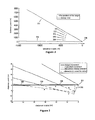
- a simulation geometry is utilized according to Figure 2.
- five point targets 19-23 are simulated, located at the same distance (4000 metres) and with an angular separation of 5°.
- the signal characteristics of the respective targets 19-23 are studied step by step in order to demonstrate the interaction of the partial elements.
- the lines 24 and 25 mark the outer limits of the radar's scan area and the reference numeral 26 marks the position of the platform.
- a distance R is calculated for each platform position where a pulse is transmitted.
- a pulse has been sent in the positions 27-30.
- the distance R extends from the respective position 27-30 towards an imaginary movement path 31 for the movement of the platform.
- the size of R is to be such that a new imaginary platform movement is created, where the momentary antenna direction is 90° relative to the movement of the imaginary platform.
- the appearance of the corrected movement is of little significance, providing that the above requirement is fulfilled.
- c the propagation speed of the signal
- ⁇ c the wavelength of the signal
- the same target areas are illuminated as in the original data collection geometry, Figure 1, but, with signal displacement having been carried out (according to T and ⁇ ), unwanted signal characteristics are eliminated, which will be discussed next.
- signal displacement having been carried out (according to T and ⁇ )
- unwanted signal characteristics are eliminated, which will be discussed next.
- In movement according to the original geometry there is an approach between platform and target area, which gives rise to two negative signal effects.
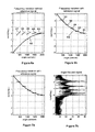
- This effect illustrated in Figure 4a, results in a distance spreading of focused targets.
- the time displacement described above with reference to Figure 3 compensates for the distance variation, whereby the signal energy of the respective target ends up in the correct distance gate.
- the size of the distance variation in Figure 4a is moderate, as low platform velocity is combined with high scan rate.
- the method proposed utilizes a reference target against which the phase variation is calculated.
- a reference function is created according to the following:
- Figure 6a illustrates the normalized frequency variation 42 of the reference function together with the corresponding values 37-41 of the illuminated targets.
- Figure 6b shows how the targets 37-41 are separated with regard to frequency by demodulation, that is to say by multiplication of signal quantity and the conjugate 43 of the reference function 42.
- the ability to separate adjacent targets increases for large antenna angles, as the frequency derivative, the gradient of the curve, increases. This is in agreement with the equation for the angular resolution discussed in the introduction to this description, according to which high resolution is obtained for large target angles.
- this re-sampling is carried out by a transformation of the non-linear angle spectrum to a linear angle scale, according to Figure 8b.
- the point targets in the simulation model are thus placed in the correct position, Figure 8c, by projecting, see the lines 44-46, 47-49, 50-52, 53-55 and 56-58, the non-linear result from Figure 8a onto a linear frequency scale, Figure 8b.
- the projection thus involves the original spectrum being displaced as a function of the difference between the linear and non-linear frequency scales.
- a radar for reconnaissance has as its main task the location of interesting objects by means of generated radar images.
- constant resolution is required. This can be achieved by suitable variation of the scan rate.
- a strength of the proposed SAR algorithm is that it also handles raw data collected with variable scan rate. As the scan rate is included in the creation of the reference function, no additional adjustment of the focusing method is required. In order to illustrate the above statement, the scene in Figure 2 is simulated, but with a variable scan rate.
- Figures 10a, 10b and Figure 11 illustrate the effect of approach movement (compare with Figures 4a, 4b and 5b).
- the illumination time varies, the size of the distance variation is angle dependent, see Figure 10a.
- the signal energy comes within the correct distance gate.
- Corresponding phase displacement results, according to Figure 11, in all the targets being centred around the frequency zero, precisely as before. The approach compensation is thus in agreement with the embodiment discussed previously.
- the creation of the reference function for demodulation/target separation is carried out according to the method described previously.
- the result is shown in Figures 12a and 12b, which illustrate the target's frequency variation 37-41, in addition to the reference function's normalized frequency 42.
- Figure 12b shows the result after demodulation.
- the conjugate of the reference function's normalized frequency is given the reference numeral 43 in Figure 12b.
- the angle-independent resolution is obtained in this state by the predefined combination between integration time and frequency derivative.
- Figure 13 illustrates the result after angle focusing of the demodulated signal quantity.
- the result is plotted here directly on a corrected angular scale in order to obtain the correct angular position.
- the result illustrates clearly that constant resolution can be also obtained when a scanning radar is utilized.
Landscapes
- Engineering & Computer Science (AREA)
- Remote Sensing (AREA)
- Radar, Positioning & Navigation (AREA)
- Physics & Mathematics (AREA)
- Electromagnetism (AREA)
- Computer Networks & Wireless Communication (AREA)
- General Physics & Mathematics (AREA)
- Radar Systems Or Details Thereof (AREA)
Claims (12)
- Verfahren zur Abbildung einer Zielszene mittels Abtastradar mit synthetischer Apertur, unter Verwendung des Doppler-Effektes, der im Fall von einer Bewegung zwischen Radar und Zielszene auftritt, wobei die Bewegung einer Plattform, auf der die Radarantenne montiert ist, unter Verwendung von Navigationsdaten, die für die Plattform erhalten worden sind, berechnet wird, dadurch gekennzeichnet, dass zur Kompensation der plattformbewegungsabhängigen Zeit und der Phasenverschiebung (7) eine empfangene Signalgröße (6) in Form von Rohdaten Impuls für Impuls in eine entsprechende bewegungskorrigierte Signalgröße (9, 10) durch Verschiebung in Zeit und Phase, umgeformt wird, in Abhängigkeit von der Bewegung der Plattform entlang einer imaginären Plattformbewegung (31), die so ausgerichtet ist, dass die momentane Antennenrichtung im Wesentlichen bei 90° zur Richtung der Bewegung der imaginären Plattform ist.
- Verfahren nach Anspruch 1, dadurch gekennzeichnet, dass die Kompensation der plattformbewegungsabhängigen Zeit und der Phasenverschiebung (7) in der Frequenzebene durchgeführt wird und dass die Größe der Zeit T und der Phase θ durch die Gleichungen erzielt wird:

und
wobei R der Abstand ist, um den ein entsprechendes Echo zu verschieben ist (Fig. 3), c die Ausbreitungsgeschwindigkeit und λc, die Wellenlänge des Signals ist. - Verfahren nach einem der vorstehenden Ansprüche, dadurch gekennzeichnet, dass die empfangene Signalgröße (3) impulskomprimiert wird (4), zweckmäßigerweise in Kombination mit der Transformation in eine bewegungskorrigierte Signalgröße (9, 10).
- Verfahren nach einem der vorstehenden Ansprüche, dadurch gekennzeichnet, dass eine Referenzfunktion (11) erzeugt wird durch:1. Plazieren eines Referenzziels in der Laufrichtung der Plattform.2. Annehmen, dass das Referenzziel über die gesamte Bewegung der Plattform und über alle Antennenwinkel beleuchtet wird.3. Berechnen der Phasenvariation θref die aufgetreten ist.4. Erzeugen eines Referenzsignals gemäß Sref = exp(j θref).5. Annähern an die Kompensation Sref.und dass die Signalgröße (9, 10) durch Multiplikation mit dem konjugierten Wert der Referenzfunktion demoduliert (11) wird.
- Verfahren nach Anspruch 4, dadurch gekennzeichnet, dass die demodulierte Signalgröße (13) durch eine recheneffiziente Fourier-Transformation (FFT) winkelfokussiert (14) wird.
- Verfahren nach Anspruch 5, dadurch gekennzeichnet, dass die winkelfokussierte Signalgröße (16) auf einen linearen Frequenzmaßstab (17) projiziert wird.
- Verfahren nach einem der vorstehenden Ansprüche, dadurch gekennzeichnet, dass die Abtastrate des Abtastradars konstant gehalten wird.
- Verfahren nach einem der vorstehenden Ansprüche 1 bis 6, dadurch gekennzeichnet, dass die Abtastrate des Abtastradars variiert (Fig. 9), um eine im Wesentlichen konstante Auflösung (Fig. 13) innerhalb des Abtastbereiches zu erzielen.
- Verfahren nach Anspruch 8, dadurch gekennzeichnet, dass die Abtastrate des Radars ωs bestimmt wird aus der Gleichung:

wobei λ der Wellenlänge des Signals entspricht, υp die Plattformgeschwindigkeit ist, RFSAR der Strahlschärfungsfaktor, 1 die physikalische Größe der Antenne und φ der Antennenwinkel ist. - Verfahren nach einem der vorstehenden Ansprüche, dadurch gekennzeichnet, dass die Abbildung der Zielszene innerhalb eines Winkelbereiches von ungefähr ± 30° während der Annäherung an die Zielszene durchgeführt wird.
- Verfahren nach einem der vorstehenden Ansprüche, dadurch gekennzeichnet, dass die Navigationsdaten der Plattform von einem INU (IMU + INS) -System, das an die Plattform angeschlossen ist, erhalten werden.
- Verfahren nach einem der vorstehenden Ansprüche, dadurch gekennzeichnet, dass andere auf Radar basierenden Abbildungsverfahren zugeordnet zu dem Verfahren in Teilen des abzubildenden Bereiches verwendet werden.
Priority Applications (5)
| Application Number | Priority Date | Filing Date | Title |
|---|---|---|---|
| AT05445017T ATE362116T1 (de) | 2005-03-29 | 2005-03-29 | Verfahren zur abbildung einer objektszene mittels abtastradar |
| EP05445017A EP1707987B1 (de) | 2005-03-29 | 2005-03-29 | Verfahren zur Abbildung einer Objektszene mittels Abtastradar |
| DE602005001113T DE602005001113T2 (de) | 2005-03-29 | 2005-03-29 | Verfahren zur Abbildung einer Zielszene mittels Abtastradar |
| ES05445017T ES2284152T3 (es) | 2005-03-29 | 2005-03-29 | Metodo para cartografiar el escenario de un objetivo utilizando un radar de exploracion. |
| US11/277,772 US7586434B1 (en) | 2005-03-29 | 2006-03-29 | Method and system for mapping a target scene using scanning radar |
Applications Claiming Priority (1)
| Application Number | Priority Date | Filing Date | Title |
|---|---|---|---|
| EP05445017A EP1707987B1 (de) | 2005-03-29 | 2005-03-29 | Verfahren zur Abbildung einer Objektszene mittels Abtastradar |
Publications (2)
| Publication Number | Publication Date |
|---|---|
| EP1707987A1 EP1707987A1 (de) | 2006-10-04 |
| EP1707987B1 true EP1707987B1 (de) | 2007-05-09 |
Family
ID=34943237
Family Applications (1)
| Application Number | Title | Priority Date | Filing Date |
|---|---|---|---|
| EP05445017A Expired - Lifetime EP1707987B1 (de) | 2005-03-29 | 2005-03-29 | Verfahren zur Abbildung einer Objektszene mittels Abtastradar |
Country Status (5)
| Country | Link |
|---|---|
| US (1) | US7586434B1 (de) |
| EP (1) | EP1707987B1 (de) |
| AT (1) | ATE362116T1 (de) |
| DE (1) | DE602005001113T2 (de) |
| ES (1) | ES2284152T3 (de) |
Families Citing this family (12)
| Publication number | Priority date | Publication date | Assignee | Title |
|---|---|---|---|---|
| US8618977B2 (en) * | 2011-01-05 | 2013-12-31 | Honeywell International Inc. | Weather radar beam-sharpening and de-quantization |
| WO2013096704A1 (en) * | 2011-12-20 | 2013-06-27 | Sadar 3D, Inc. | Systems, apparatus, and methods for acquisition and use of image data |
| US11137490B2 (en) * | 2014-09-16 | 2021-10-05 | Teknologian Tutkimuskeskus Vtt | Navigational aid with adaptive radar |
| EP3517996B1 (de) * | 2018-01-25 | 2022-09-07 | Aptiv Technologies Limited | Verfahren zur bestimmung der position eines fahrzeugs |
| EP3599484A1 (de) * | 2018-07-23 | 2020-01-29 | Acconeer AB | Sich selbständig bewegendes objekt |
| CN112180368B (zh) * | 2020-09-10 | 2022-07-15 | 中国科学院空天信息创新研究院 | 多通道滑动聚束sar的数据处理方法、设备、系统及介质 |
| CN112612026B (zh) * | 2020-11-20 | 2022-06-21 | 哈尔滨工业大学 | 基于双雷达距离像融合的目标角分辨方法 |
| CN113625269B (zh) * | 2021-08-26 | 2024-03-01 | 长沙理工大学 | 一种基于毫米波雷达的高速铁路钢轨沉降检测方法和系统 |
| CN114371452B (zh) * | 2022-03-21 | 2022-07-08 | 北京宏锐星通科技有限公司 | 对合成孔径雷达运动补偿的干扰方法及干扰装置 |
| CN117554921B (zh) * | 2024-01-12 | 2024-03-29 | 西安中创云图科技有限公司 | 一种探地雷达三维场景正演方法 |
| CN118632400B (zh) * | 2024-07-03 | 2025-11-11 | 明迈智能科技股份有限公司 | 一种基于多信息融合的防爆led照明方法及系统 |
| CN119893280B (zh) * | 2025-01-06 | 2025-12-02 | 中国人民解放军国防科技大学 | 一种基于平静水面的成像方法和装置 |
Family Cites Families (9)
| Publication number | Priority date | Publication date | Assignee | Title |
|---|---|---|---|---|
| US3609762A (en) * | 1966-11-07 | 1971-09-28 | Goodyear Aerospace | Direct gradient-correlation apparatus |
| US4134113A (en) * | 1977-04-18 | 1979-01-09 | Westinghouse Electric Corporation | Monopulse motion compensation for a synthetic aperture radar |
| US5245347A (en) * | 1980-12-29 | 1993-09-14 | Raytheon Company | All weather tactical strike system (AWTSS) and method of operation |
| US5608404A (en) * | 1993-06-23 | 1997-03-04 | The United States Of America As Represented By The United States Department Of Energy | Imaging synthetic aperture radar |
| DE4427657C2 (de) * | 1994-08-05 | 1996-10-24 | Deutsche Forsch Luft Raumfahrt | Verfahren zur Bilderzeugung mittels einer zweidimensionalen Datenverarbeitung bei einem Radar mit synthetischer Apertur |
| US7095488B2 (en) * | 2003-01-21 | 2006-08-22 | Rosemount Aerospace Inc. | System for profiling objects on terrain forward and below an aircraft utilizing a cross-track laser altimeter |
| US6750809B1 (en) * | 2003-04-15 | 2004-06-15 | Raytheon Company | High resolution SAR processing using stepped frequency chirp waveform |
| US6885334B1 (en) * | 2004-04-06 | 2005-04-26 | Honeywell International Inc. | Methods and systems for detecting forward obstacles |
| US7145497B2 (en) * | 2005-01-07 | 2006-12-05 | Raytheon Company | Robust detection technique of fixed and moving ground targets using a common waveform |
-
2005
- 2005-03-29 ES ES05445017T patent/ES2284152T3/es not_active Expired - Lifetime
- 2005-03-29 AT AT05445017T patent/ATE362116T1/de not_active IP Right Cessation
- 2005-03-29 DE DE602005001113T patent/DE602005001113T2/de not_active Expired - Lifetime
- 2005-03-29 EP EP05445017A patent/EP1707987B1/de not_active Expired - Lifetime
-
2006
- 2006-03-29 US US11/277,772 patent/US7586434B1/en active Active
Non-Patent Citations (1)
| Title |
|---|
| None * |
Also Published As
| Publication number | Publication date |
|---|---|
| ES2284152T3 (es) | 2007-11-01 |
| US20090231185A1 (en) | 2009-09-17 |
| US7586434B1 (en) | 2009-09-08 |
| DE602005001113D1 (de) | 2007-06-21 |
| DE602005001113T2 (de) | 2008-01-10 |
| ATE362116T1 (de) | 2007-06-15 |
| EP1707987A1 (de) | 2006-10-04 |
Similar Documents
| Publication | Publication Date | Title |
|---|---|---|
| EP2998763B1 (de) | Phasenkalibrierung eines stepped-chirp-signals für radar mit synthetischer apertur | |
| Meta et al. | TOPS imaging with TerraSAR-X: Mode design and performance analysis | |
| US7212149B2 (en) | System, method and computer program product for detecting and tracking a moving ground target having a single phase center antenna | |
| EP1505408B1 (de) | Verfahren zur SAR- Verarbeitung ohne INS-Dateien | |
| US9417323B2 (en) | SAR point cloud generation system | |
| US5812082A (en) | Method for azimuth scaling of SAR data and highly accurate processor for two-dimensional processing of scanSAR data | |
| Neo et al. | Processing of azimuth-invariant bistatic SAR data using the range Doppler algorithm | |
| US5394151A (en) | Apparatus and method for producing three-dimensional images | |
| Liu et al. | Bistatic SAR data focusing using an omega-K algorithm based on method of series reversion | |
| Pastina et al. | Multistatic and MIMO distributed ISAR for enhanced cross-range resolution of rotating targets | |
| CA2020645C (en) | Method for extracting motion errors of a platform carrying a coherent imaging radar system from the raw radar data and device for executing the method | |
| US5045855A (en) | Method for extracting motion errors of a platform carrying a coherent imaging radar system from the raw radar data and device for executing the method | |
| US7064702B1 (en) | System, method and computer program product for reducing quadratic phase errors in synthetic aperture radar signals | |
| EP1707987B1 (de) | Verfahren zur Abbildung einer Objektszene mittels Abtastradar | |
| CN102680974B (zh) | 一种星载滑动聚束合成孔径雷达的信号处理方法 | |
| CN107390181B (zh) | 一种基于多波束扫描的雷达高分辨成像方法 | |
| Li et al. | Autofocus correction of residual RCM for VHR SAR sensors with light-small aircraft | |
| Magnard et al. | Processing of MEMPHIS Ka-band multibaseline interferometric SAR data: From raw data to digital surface models | |
| US6853330B1 (en) | Inverse precision velocity update for monopulse calibration | |
| Petty et al. | Field-of-view characteristics and resolution matching for the Global Precipitation Measurement (GPM) Microwave Imager (GMI) | |
| Reigber et al. | Wavenumber domain SAR focusing with integrated motion compensation | |
| Yang | Study on ground moving target indication and imaging technique of airborne SAR | |
| JPH0829528A (ja) | レーダ装置 | |
| Dawidowicz et al. | First polish SAR trials | |
| Prats-Iraola et al. | The BIOMASS ground processor prototype: An overview |
Legal Events
| Date | Code | Title | Description |
|---|---|---|---|
| PUAI | Public reference made under article 153(3) epc to a published international application that has entered the european phase |
Free format text: ORIGINAL CODE: 0009012 |
|
| 17P | Request for examination filed |
Effective date: 20060315 |
|
| AK | Designated contracting states |
Kind code of ref document: A1 Designated state(s): AT BE BG CH CY CZ DE DK EE ES FI FR GB GR HU IE IS IT LI LT LU MC NL PL PT RO SE SI SK TR |
|
| AX | Request for extension of the european patent |
Extension state: AL BA HR LV MK YU |
|
| GRAP | Despatch of communication of intention to grant a patent |
Free format text: ORIGINAL CODE: EPIDOSNIGR1 |
|
| GRAS | Grant fee paid |
Free format text: ORIGINAL CODE: EPIDOSNIGR3 |
|
| GRAA | (expected) grant |
Free format text: ORIGINAL CODE: 0009210 |
|
| AK | Designated contracting states |
Kind code of ref document: B1 Designated state(s): AT BE BG CH CY CZ DE DK EE ES FI FR GB GR HU IE IS IT LI LT LU MC NL PL PT RO SE SI SK TR |
|
| PG25 | Lapsed in a contracting state [announced via postgrant information from national office to epo] |
Ref country code: LI Free format text: LAPSE BECAUSE OF FAILURE TO SUBMIT A TRANSLATION OF THE DESCRIPTION OR TO PAY THE FEE WITHIN THE PRESCRIBED TIME-LIMIT Effective date: 20070509 Ref country code: CH Free format text: LAPSE BECAUSE OF FAILURE TO SUBMIT A TRANSLATION OF THE DESCRIPTION OR TO PAY THE FEE WITHIN THE PRESCRIBED TIME-LIMIT Effective date: 20070509 Ref country code: FI Free format text: LAPSE BECAUSE OF FAILURE TO SUBMIT A TRANSLATION OF THE DESCRIPTION OR TO PAY THE FEE WITHIN THE PRESCRIBED TIME-LIMIT Effective date: 20070509 |
|
| REG | Reference to a national code |
Ref country code: GB Ref legal event code: FG4D |
|
| REG | Reference to a national code |
Ref country code: CH Ref legal event code: EP |
|
| AKX | Designation fees paid |
Designated state(s): AT BE BG CH CY CZ DE DK EE ES FI FR GB GR HU IE IS IT LI LT LU MC NL PL PT RO SE SI SK TR |
|
| REG | Reference to a national code |
Ref country code: IE Ref legal event code: FG4D |
|
| REF | Corresponds to: |
Ref document number: 602005001113 Country of ref document: DE Date of ref document: 20070621 Kind code of ref document: P |
|
| PG25 | Lapsed in a contracting state [announced via postgrant information from national office to epo] |
Ref country code: SE Free format text: LAPSE BECAUSE OF FAILURE TO SUBMIT A TRANSLATION OF THE DESCRIPTION OR TO PAY THE FEE WITHIN THE PRESCRIBED TIME-LIMIT Effective date: 20070809 |
|
| ET | Fr: translation filed | ||
| PG25 | Lapsed in a contracting state [announced via postgrant information from national office to epo] |
Ref country code: IS Free format text: LAPSE BECAUSE OF FAILURE TO SUBMIT A TRANSLATION OF THE DESCRIPTION OR TO PAY THE FEE WITHIN THE PRESCRIBED TIME-LIMIT Effective date: 20070909 |
|
| NLV1 | Nl: lapsed or annulled due to failure to fulfill the requirements of art. 29p and 29m of the patents act | ||
| REG | Reference to a national code |
Ref country code: ES Ref legal event code: FG2A Ref document number: 2284152 Country of ref document: ES Kind code of ref document: T3 |
|
| REG | Reference to a national code |
Ref country code: CH Ref legal event code: PL |
|
| PG25 | Lapsed in a contracting state [announced via postgrant information from national office to epo] |
Ref country code: AT Free format text: LAPSE BECAUSE OF FAILURE TO SUBMIT A TRANSLATION OF THE DESCRIPTION OR TO PAY THE FEE WITHIN THE PRESCRIBED TIME-LIMIT Effective date: 20070509 Ref country code: PL Free format text: LAPSE BECAUSE OF FAILURE TO SUBMIT A TRANSLATION OF THE DESCRIPTION OR TO PAY THE FEE WITHIN THE PRESCRIBED TIME-LIMIT Effective date: 20070509 |
|
| PG25 | Lapsed in a contracting state [announced via postgrant information from national office to epo] |
Ref country code: BE Free format text: LAPSE BECAUSE OF FAILURE TO SUBMIT A TRANSLATION OF THE DESCRIPTION OR TO PAY THE FEE WITHIN THE PRESCRIBED TIME-LIMIT Effective date: 20070509 |
|
| PG25 | Lapsed in a contracting state [announced via postgrant information from national office to epo] |
Ref country code: PT Free format text: LAPSE BECAUSE OF FAILURE TO SUBMIT A TRANSLATION OF THE DESCRIPTION OR TO PAY THE FEE WITHIN THE PRESCRIBED TIME-LIMIT Effective date: 20071009 Ref country code: DK Free format text: LAPSE BECAUSE OF FAILURE TO SUBMIT A TRANSLATION OF THE DESCRIPTION OR TO PAY THE FEE WITHIN THE PRESCRIBED TIME-LIMIT Effective date: 20070509 Ref country code: NL Free format text: LAPSE BECAUSE OF FAILURE TO SUBMIT A TRANSLATION OF THE DESCRIPTION OR TO PAY THE FEE WITHIN THE PRESCRIBED TIME-LIMIT Effective date: 20070509 Ref country code: SI Free format text: LAPSE BECAUSE OF FAILURE TO SUBMIT A TRANSLATION OF THE DESCRIPTION OR TO PAY THE FEE WITHIN THE PRESCRIBED TIME-LIMIT Effective date: 20070509 Ref country code: CZ Free format text: LAPSE BECAUSE OF FAILURE TO SUBMIT A TRANSLATION OF THE DESCRIPTION OR TO PAY THE FEE WITHIN THE PRESCRIBED TIME-LIMIT Effective date: 20070509 Ref country code: BG Free format text: LAPSE BECAUSE OF FAILURE TO SUBMIT A TRANSLATION OF THE DESCRIPTION OR TO PAY THE FEE WITHIN THE PRESCRIBED TIME-LIMIT Effective date: 20070809 |
|
| PG25 | Lapsed in a contracting state [announced via postgrant information from national office to epo] |
Ref country code: LT Free format text: LAPSE BECAUSE OF FAILURE TO SUBMIT A TRANSLATION OF THE DESCRIPTION OR TO PAY THE FEE WITHIN THE PRESCRIBED TIME-LIMIT Effective date: 20070509 Ref country code: SK Free format text: LAPSE BECAUSE OF FAILURE TO SUBMIT A TRANSLATION OF THE DESCRIPTION OR TO PAY THE FEE WITHIN THE PRESCRIBED TIME-LIMIT Effective date: 20070509 |
|
| PLBE | No opposition filed within time limit |
Free format text: ORIGINAL CODE: 0009261 |
|
| STAA | Information on the status of an ep patent application or granted ep patent |
Free format text: STATUS: NO OPPOSITION FILED WITHIN TIME LIMIT |
|
| 26N | No opposition filed |
Effective date: 20080212 |
|
| PG25 | Lapsed in a contracting state [announced via postgrant information from national office to epo] |
Ref country code: GR Free format text: LAPSE BECAUSE OF FAILURE TO SUBMIT A TRANSLATION OF THE DESCRIPTION OR TO PAY THE FEE WITHIN THE PRESCRIBED TIME-LIMIT Effective date: 20070810 |
|
| PG25 | Lapsed in a contracting state [announced via postgrant information from national office to epo] |
Ref country code: RO Free format text: LAPSE BECAUSE OF FAILURE TO SUBMIT A TRANSLATION OF THE DESCRIPTION OR TO PAY THE FEE WITHIN THE PRESCRIBED TIME-LIMIT Effective date: 20070509 |
|
| PG25 | Lapsed in a contracting state [announced via postgrant information from national office to epo] |
Ref country code: MC Free format text: LAPSE BECAUSE OF NON-PAYMENT OF DUE FEES Effective date: 20080331 |
|
| PG25 | Lapsed in a contracting state [announced via postgrant information from national office to epo] |
Ref country code: EE Free format text: LAPSE BECAUSE OF FAILURE TO SUBMIT A TRANSLATION OF THE DESCRIPTION OR TO PAY THE FEE WITHIN THE PRESCRIBED TIME-LIMIT Effective date: 20070509 Ref country code: IE Free format text: LAPSE BECAUSE OF NON-PAYMENT OF DUE FEES Effective date: 20080331 |
|
| PG25 | Lapsed in a contracting state [announced via postgrant information from national office to epo] |
Ref country code: CY Free format text: LAPSE BECAUSE OF FAILURE TO SUBMIT A TRANSLATION OF THE DESCRIPTION OR TO PAY THE FEE WITHIN THE PRESCRIBED TIME-LIMIT Effective date: 20070509 |
|
| PG25 | Lapsed in a contracting state [announced via postgrant information from national office to epo] |
Ref country code: LU Free format text: LAPSE BECAUSE OF NON-PAYMENT OF DUE FEES Effective date: 20080329 Ref country code: HU Free format text: LAPSE BECAUSE OF FAILURE TO SUBMIT A TRANSLATION OF THE DESCRIPTION OR TO PAY THE FEE WITHIN THE PRESCRIBED TIME-LIMIT Effective date: 20071110 |
|
| PG25 | Lapsed in a contracting state [announced via postgrant information from national office to epo] |
Ref country code: TR Free format text: LAPSE BECAUSE OF FAILURE TO SUBMIT A TRANSLATION OF THE DESCRIPTION OR TO PAY THE FEE WITHIN THE PRESCRIBED TIME-LIMIT Effective date: 20070509 |
|
| REG | Reference to a national code |
Ref country code: FR Ref legal event code: PLFP Year of fee payment: 12 |
|
| REG | Reference to a national code |
Ref country code: FR Ref legal event code: PLFP Year of fee payment: 13 |
|
| REG | Reference to a national code |
Ref country code: FR Ref legal event code: PLFP Year of fee payment: 14 |
|
| REG | Reference to a national code |
Ref country code: DE Ref legal event code: R082 Ref document number: 602005001113 Country of ref document: DE Representative=s name: GLAWE DELFS MOLL PARTNERSCHAFT MBB VON PATENT-, DE Ref country code: DE Ref legal event code: R082 Ref document number: 602005001113 Country of ref document: DE Representative=s name: GLAWE DELFS MOLL PARTGMBB, DE |
|
| PGFP | Annual fee paid to national office [announced via postgrant information from national office to epo] |
Ref country code: DE Payment date: 20231103 Year of fee payment: 20 Ref country code: GB Payment date: 20240125 Year of fee payment: 20 |
|
| PGFP | Annual fee paid to national office [announced via postgrant information from national office to epo] |
Ref country code: IT Payment date: 20231116 Year of fee payment: 20 Ref country code: FR Payment date: 20240129 Year of fee payment: 20 |
|
| PGFP | Annual fee paid to national office [announced via postgrant information from national office to epo] |
Ref country code: ES Payment date: 20240401 Year of fee payment: 20 |
|
| REG | Reference to a national code |
Ref country code: DE Ref legal event code: R071 Ref document number: 602005001113 Country of ref document: DE |
|
| REG | Reference to a national code |
Ref country code: ES Ref legal event code: FD2A Effective date: 20250404 |
|
| PG25 | Lapsed in a contracting state [announced via postgrant information from national office to epo] |
Ref country code: ES Free format text: LAPSE BECAUSE OF EXPIRATION OF PROTECTION Effective date: 20250330 |
|
| REG | Reference to a national code |
Ref country code: GB Ref legal event code: PE20 Expiry date: 20250328 |
|
| PG25 | Lapsed in a contracting state [announced via postgrant information from national office to epo] |
Ref country code: GB Free format text: LAPSE BECAUSE OF EXPIRATION OF PROTECTION Effective date: 20250328 |