EP1707443A1 - Power supply apparatus for sliding door - Google Patents
Power supply apparatus for sliding door Download PDFInfo
- Publication number
- EP1707443A1 EP1707443A1 EP06251536A EP06251536A EP1707443A1 EP 1707443 A1 EP1707443 A1 EP 1707443A1 EP 06251536 A EP06251536 A EP 06251536A EP 06251536 A EP06251536 A EP 06251536A EP 1707443 A1 EP1707443 A1 EP 1707443A1
- Authority
- EP
- European Patent Office
- Prior art keywords
- power supply
- supply line
- case
- sliding door
- roller
- Prior art date
- Legal status (The legal status is an assumption and is not a legal conclusion. Google has not performed a legal analysis and makes no representation as to the accuracy of the status listed.)
- Granted
Links
- 230000001012 protector Effects 0.000 claims abstract description 35
- 230000006835 compression Effects 0.000 claims description 25
- 238000007906 compression Methods 0.000 claims description 25
- 238000005452 bending Methods 0.000 description 7
- 238000004519 manufacturing process Methods 0.000 description 3
- 239000000057 synthetic resin Substances 0.000 description 2
- 229920003002 synthetic resin Polymers 0.000 description 2
- 230000001154 acute effect Effects 0.000 description 1
- 230000008602 contraction Effects 0.000 description 1
- 230000001627 detrimental effect Effects 0.000 description 1
- 238000009434 installation Methods 0.000 description 1
- 230000010354 integration Effects 0.000 description 1
- 239000000463 material Substances 0.000 description 1
- 239000002184 metal Substances 0.000 description 1
- 238000000034 method Methods 0.000 description 1
- 230000000149 penetrating effect Effects 0.000 description 1
- 239000000088 plastic resin Substances 0.000 description 1
- 230000001681 protective effect Effects 0.000 description 1
- 238000004513 sizing Methods 0.000 description 1
- 239000000126 substance Substances 0.000 description 1
Images






Classifications
-
- E—FIXED CONSTRUCTIONS
- E05—LOCKS; KEYS; WINDOW OR DOOR FITTINGS; SAFES
- E05F—DEVICES FOR MOVING WINGS INTO OPEN OR CLOSED POSITION; CHECKS FOR WINGS; WING FITTINGS NOT OTHERWISE PROVIDED FOR, CONCERNED WITH THE FUNCTIONING OF THE WING
- E05F15/00—Power-operated mechanisms for wings
- E05F15/60—Power-operated mechanisms for wings using electrical actuators
- E05F15/603—Power-operated mechanisms for wings using electrical actuators using rotary electromotors
- E05F15/632—Power-operated mechanisms for wings using electrical actuators using rotary electromotors for horizontally-sliding wings
- E05F15/655—Power-operated mechanisms for wings using electrical actuators using rotary electromotors for horizontally-sliding wings specially adapted for vehicle wings
-
- B—PERFORMING OPERATIONS; TRANSPORTING
- B60—VEHICLES IN GENERAL
- B60R—VEHICLES, VEHICLE FITTINGS, OR VEHICLE PARTS, NOT OTHERWISE PROVIDED FOR
- B60R16/00—Electric or fluid circuits specially adapted for vehicles and not otherwise provided for; Arrangement of elements of electric or fluid circuits specially adapted for vehicles and not otherwise provided for
- B60R16/02—Electric or fluid circuits specially adapted for vehicles and not otherwise provided for; Arrangement of elements of electric or fluid circuits specially adapted for vehicles and not otherwise provided for electric constitutive elements
- B60R16/0207—Wire harnesses
- B60R16/0215—Protecting, fastening and routing means therefor
- B60R16/0222—Grommets
-
- B—PERFORMING OPERATIONS; TRANSPORTING
- B60—VEHICLES IN GENERAL
- B60J—WINDOWS, WINDSCREENS, NON-FIXED ROOFS, DOORS, OR SIMILAR DEVICES FOR VEHICLES; REMOVABLE EXTERNAL PROTECTIVE COVERINGS SPECIALLY ADAPTED FOR VEHICLES
- B60J5/00—Doors
- B60J5/04—Doors arranged at the vehicle sides
- B60J5/06—Doors arranged at the vehicle sides slidable; foldable
-
- B—PERFORMING OPERATIONS; TRANSPORTING
- B60—VEHICLES IN GENERAL
- B60R—VEHICLES, VEHICLE FITTINGS, OR VEHICLE PARTS, NOT OTHERWISE PROVIDED FOR
- B60R16/00—Electric or fluid circuits specially adapted for vehicles and not otherwise provided for; Arrangement of elements of electric or fluid circuits specially adapted for vehicles and not otherwise provided for
- B60R16/02—Electric or fluid circuits specially adapted for vehicles and not otherwise provided for; Arrangement of elements of electric or fluid circuits specially adapted for vehicles and not otherwise provided for electric constitutive elements
- B60R16/03—Electric or fluid circuits specially adapted for vehicles and not otherwise provided for; Arrangement of elements of electric or fluid circuits specially adapted for vehicles and not otherwise provided for electric constitutive elements for supply of electrical power to vehicle subsystems or for
-
- B—PERFORMING OPERATIONS; TRANSPORTING
- B60—VEHICLES IN GENERAL
- B60Y—INDEXING SCHEME RELATING TO ASPECTS CROSS-CUTTING VEHICLE TECHNOLOGY
- B60Y2200/00—Type of vehicle
- B60Y2200/10—Road Vehicles
- B60Y2200/11—Passenger cars; Automobiles
-
- E—FIXED CONSTRUCTIONS
- E05—LOCKS; KEYS; WINDOW OR DOOR FITTINGS; SAFES
- E05Y—INDEXING SCHEME ASSOCIATED WITH SUBCLASSES E05D AND E05F, RELATING TO CONSTRUCTION ELEMENTS, ELECTRIC CONTROL, POWER SUPPLY, POWER SIGNAL OR TRANSMISSION, USER INTERFACES, MOUNTING OR COUPLING, DETAILS, ACCESSORIES, AUXILIARY OPERATIONS NOT OTHERWISE PROVIDED FOR, APPLICATION THEREOF
- E05Y2201/00—Constructional elements; Accessories therefor
- E05Y2201/40—Motors; Magnets; Springs; Weights; Accessories therefor
- E05Y2201/47—Springs
-
- E—FIXED CONSTRUCTIONS
- E05—LOCKS; KEYS; WINDOW OR DOOR FITTINGS; SAFES
- E05Y—INDEXING SCHEME ASSOCIATED WITH SUBCLASSES E05D AND E05F, RELATING TO CONSTRUCTION ELEMENTS, ELECTRIC CONTROL, POWER SUPPLY, POWER SIGNAL OR TRANSMISSION, USER INTERFACES, MOUNTING OR COUPLING, DETAILS, ACCESSORIES, AUXILIARY OPERATIONS NOT OTHERWISE PROVIDED FOR, APPLICATION THEREOF
- E05Y2201/00—Constructional elements; Accessories therefor
- E05Y2201/40—Motors; Magnets; Springs; Weights; Accessories therefor
- E05Y2201/47—Springs
- E05Y2201/474—Compression springs
-
- E—FIXED CONSTRUCTIONS
- E05—LOCKS; KEYS; WINDOW OR DOOR FITTINGS; SAFES
- E05Y—INDEXING SCHEME ASSOCIATED WITH SUBCLASSES E05D AND E05F, RELATING TO CONSTRUCTION ELEMENTS, ELECTRIC CONTROL, POWER SUPPLY, POWER SIGNAL OR TRANSMISSION, USER INTERFACES, MOUNTING OR COUPLING, DETAILS, ACCESSORIES, AUXILIARY OPERATIONS NOT OTHERWISE PROVIDED FOR, APPLICATION THEREOF
- E05Y2201/00—Constructional elements; Accessories therefor
- E05Y2201/60—Suspension or transmission members; Accessories therefor
- E05Y2201/622—Suspension or transmission members elements
- E05Y2201/708—Sliders
-
- E—FIXED CONSTRUCTIONS
- E05—LOCKS; KEYS; WINDOW OR DOOR FITTINGS; SAFES
- E05Y—INDEXING SCHEME ASSOCIATED WITH SUBCLASSES E05D AND E05F, RELATING TO CONSTRUCTION ELEMENTS, ELECTRIC CONTROL, POWER SUPPLY, POWER SIGNAL OR TRANSMISSION, USER INTERFACES, MOUNTING OR COUPLING, DETAILS, ACCESSORIES, AUXILIARY OPERATIONS NOT OTHERWISE PROVIDED FOR, APPLICATION THEREOF
- E05Y2400/00—Electronic control; Electrical power; Power supply; Power or signal transmission; User interfaces
- E05Y2400/61—Power supply
-
- E—FIXED CONSTRUCTIONS
- E05—LOCKS; KEYS; WINDOW OR DOOR FITTINGS; SAFES
- E05Y—INDEXING SCHEME ASSOCIATED WITH SUBCLASSES E05D AND E05F, RELATING TO CONSTRUCTION ELEMENTS, ELECTRIC CONTROL, POWER SUPPLY, POWER SIGNAL OR TRANSMISSION, USER INTERFACES, MOUNTING OR COUPLING, DETAILS, ACCESSORIES, AUXILIARY OPERATIONS NOT OTHERWISE PROVIDED FOR, APPLICATION THEREOF
- E05Y2900/00—Application of doors, windows, wings or fittings thereof
- E05Y2900/50—Application of doors, windows, wings or fittings thereof for vehicles
- E05Y2900/53—Type of wing
- E05Y2900/531—Doors
Definitions
- Devices, systems, and methods consistent with the invention relate to a power supply apparatus for a sliding door in a motor vehicle such as a minivan (a so-called one-box car), wherein the sliding door and a vehicle body are electrically coupled to one another via a power supply line in order to regularly supply electrical power to the sliding door.
- a motor vehicle such as a minivan (a so-called one-box car)
- the sliding door and a vehicle body are electrically coupled to one another via a power supply line in order to regularly supply electrical power to the sliding door.
- a structure in which a power supply line is laid extending from a vehicle body to the sliding door in order to regularly supply electrical power and electrical signals to devices such as electric appliances in the sliding door.
- the power supply line is housed in a protector, which is made of plastic and installed in the sliding door, in a manner such that the power supply line is in a bending state inside the protector in order that expansion and contraction of the power supply line due to opening and closing movement of the sliding door can be absorbed or compensated.
- a structure in which a protector has a slit-shaped opening along which a flanged guide portion whose longitudinal cross section has a curved-shape or slanted-shape is formed, in which a power supply line guidance portion is formed on the edge of the flanged guide portion, and is gradually curved or slanted in the height-wise direction, and in which an opening portion for leading out a power supply line is formed adjacent to the power supply line guidance portion such that it is connected to the slit-shaped opening is known from Japanese Unexamined Patent Application, First Publication No. 2003-335188 .
- the power supply line oscillates along the flanged guide portion at a time of opening and closing the sliding door, and smoothly climbs from an end of the slit-shaped opening along the power supply line guidance portion. Therefore, if a power supply line stationary portion at a vehicle body side is located at a position higher than the slit-shaped opening, an opening portion for guiding the power supply line has the same level of height as the power supply line stationary portion when the sliding door is, for example, fully closed.
- the power supply line is never folded in a U-turn manner with a small diameter in the vertical direction, and therefore, application of excessive bending force to the power supply line can be avoided.
- the power supply line is caught by the power supply line guidance portion and smoothly guided by the flanged guide portion without being tangled.
- the power supply line being drawn out through the slit-shaped opening is rendered curved or slanted and then smoothly bent in the height-wise direction.
- the sliding door is fully closed, the sliding door is substantially outwardly separated from the vehicle body.
- a bending radius along the flanged guide portion becomes large such that application of excessive bending force to the power supply line can be avoided.
- One conventional protector is formed relatively large in a snail-shape in order to prevent the power supply line from being repeatedly bent with a small diameter in a U-turn manner. Namely, the protector is relative large to form such a snail-shape. If such large protectors are used for production, disadvantages in terms of production costs are generated. In addition thereto, since such a large protector is incorporated inside the sliding door, the locations on which other appliances can be provided are limited, thus resulting in poor design in terms of the layout inside the door.
- an aspect of the present invention is to provide a power supply apparatus for a sliding door, enabling down-sizing, avoiding the detrimental influence caused by repeated bending, and easing a design of components layout inside the door.
- a power supply apparatus for a vehicular sliding door including a power supply line which is electrically connected to a power supply to supply electrical power to electrical appliances inside the sliding door; a power supply line protector which includes a rectangular-shaped case and is disposed in the sliding door and in which the power supply line is housed in a bent state; a power supply line path which is provided in the case of the power supply line protector and which controls the bent state of the power supply line; a slider which is received in, and slidable along a length of, the case; an extension spring by which the slider is normally urged toward one end side of the case; and a slit-shaped opening which is formed in an underside of the case and which covers a range of sliding of the slider; wherein a power supply side portion of the power supply line is drawn out through the opening of the case and then secured to a vehicle body side; and wherein a power supply line portion, which has been drawn out from another end side of the case, is
- the slider may include a distal end member along the contour of which the power supply line is bent so that a power supply line portion from a power supply line path side to an upper side thereof is curved; a base end member to which the extension spring is connected; and a connecting member through which the distal end member and the base end member are connected.
- the power supply line in the case may be inserted in a sheath member.
- the extension spring may consist of a coil spring bent in a U-shape.
- the power supply line protector may be integrally formed with a module plate into which appliances to be disposed in the sliding door are incorporated.
- a power supply apparatus for a vehicular sliding door including a power supply line which is electrically connected to a power supply to supply electrical power to electrical appliances inside the sliding door; a power supply line protector which includes a rectangular-shaped case and is disposed in the sliding door and in which the power supply line is housed in a bent state; a compression spring a base end of which is secured to one end side of the inside of the case; and a roller which is disposed at a front end of the compression spring and which rolls within the case, the periphery of the roller being round; wherein the power supply line is extracted through the one end side of the case and through an opening of the case and then connected to the power supply, a partway portion of the power supply line being traversed over the roller in the case; wherein when the sliding door is in an opened state, the partway portion of the power supply line is extracted out of the case and the compression spring is compressed by the roller; and wherein the roller is pushed back due to
- the compression spring may consist of a plate spring bent in a zigzag manner.
- a power supply line protector 1 includes a rectangular-shaped case 2 inside of which a power supply line 3 is housed in a curved or bent state to supply electrical power to electric appliances in the sliding door.
- a power supply line path 5 is provided in the case 2 to control bending of the power supply line 3.
- a slider 4 is provided in the case 2 so as to slide along a lengthwise direction of the case 2.
- the slider 4 is comprised of a distal end member 6 having a rounded portion, a connecting member 7, and a base end member 8 that is connected to the distal end member 6 through the connecting member 7.
- the power supply line 3 is guided by and curved along a surface (the contour) from a power supply path side to an upper side of the rounded portion of the distal end member 6.
- the aforementioned connecting member 7 is a thin plate-shaped member and enables a sliding operation of the slider 4 in the case 2. More specifically, the connecting member 7 of the slider 4 has upper and lower ends, which are fitted in respective rails or recesses (not shown in the drawings) such that the slider 4 is slidable along the rails.
- the slider 4 is connected to an extension spring 9, which normally urges the slider 4 toward one end side of the case 2.
- This extension spring 9 is inserted in a U-shaped protective case 10 such that a coil spring constituting the extension spring 9 is generally curved so as to present a U-shaped configuration.
- This extension spring 9 has ends both of which are fixedly connected to the base end member 8 of the slider 4 such that the slider 4 is normally urged in a leftward direction in Fig. 1.
- the power supply line 3 is inserted in a sheath member 11 for protection thereof.
- a corrugated tube made of plastic resin, or other suitable material known in the art can advantageously be used.
- One end of the power supply line 3 or a portion 3A which is drawn out from the power supply line path 5 through a below-mentioned opening 12 is fixed to a vehicle body for electrical connection to a power supply.
- Another portion 3B (or another end of the power supply line 3) which is drawn out through an opening 2A of another end of the case 2, is connected to appliances inside the sliding door.
- a slit-shaped opening 12 whose dimension corresponds to a sliding length of the slider 4 is provided on the underside of the case 2. The supply line 3 is moved or slid along the opening 12 while penetrating therethrough.
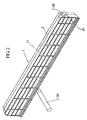
- Fig. 2 illustrates a state in which a cover 13 is secured to one side surface of the case 2 of Fig. 1.
- the power supply line 3 is drawn out through the opening 2A of the aforesaid another end of the case 2 and then connected to the appliances inside the sliding door.
- the power supply line 3 is also drawn out through the opening 12 via the power supply line path 5 and then fixed to the vehicle body (not shown) for electrical connection to the power supply.
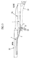
- Fig. 3 is a view to explain operation of the apparatus of the present exemplary embodiment when a sliding door 20 is opened and closed.
- the power supply line 3 is secured to the vehicle body, and more specifically to a stepped portion thereof, and has a connector 23 at its leading end.
- the connector 23 is connected to a wire harness which is extended from the power supply.
- Fig. 4 illustrates a simplified inner structure of the power supply line protector 1 when the sliding door 20 is in a open state, or occupies a position shown at a left side in Fig. 3.
- Fig. 5 illustrates the simplified inner structure of the power supply protector 1 when the sliding door 20 is in a fully closed state. In the fully opened state, the power supply line 3 in the case 2 is drawn out through the opening 12 lengthily to the outside. In the fully closed state, a greater part of the power supply line 3 is received in the case 2.
- Fig. 6 is a view to explain a general concept of the sliding door 20 being slid from a closed state to an opened state.
- the power supply line 3 is fixed to the vehicle body 21 by the stationary portion 22 at one end side (or the portion 3A) of the power supply line 3.
- the power supply line 3 is positioned such that it follows the contour of the distal end member 6 of the slider 4.
- the case 2 (the power supply protector 1) is slid along with the sliding door 20, and therefore, the power supply line 3 causes the slide 4 to move.
- the power supply line 3 it is advantageous to use a wire harness having a circular cross-section rather than a wire harness having a flat shape, in terms of strength.
- the sheath member 11 is advantageously formed in a cylindrical shape.
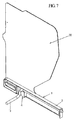
- Figs. 7 and 8 illustrate a module plate 30 and the case 2, both of which are integrally formed with one another and made of synthetic resin, the latter figure illustrating a state in which the cover 13 is secured to one side thereof.
- a typical door module is structured by a module plate and by parts, i.e., a power window in a door, an actuator for self-locking, a regulator, and other parts known in the art, mounted on the module plate, wherein the module plate with the parts mounted thereon is installed in an opening formed in an inner panel of the door at the same time as one unit.
- a structure is formed in which a module plate and a case are injection-molded to be integrally formed with one another and in which a regular power supply line protector is integrated with a door module.
- Fig. 9 is a perspective view illustrating a power supply line protector 101 to be incorporated in a vehicle body, without an upper case 102 (see Fig. 11).
- a compression spring 104 is secured to one end of a lower case 103 (referred to simply as a "case") at a base end thereof.
- a circumferentially circular roller 105 is disposed at a leading end of the compression spring 104 and rolls inside the lower case 103.
- An illustrated groove is formed on the periphery of the roller 105 so as to present a pulley wheel, along, or in which, a power supply line 110 can run.
- One end of the power supply line 110 which has been drawn out of a right end, in Fig. 9, of the lower case 103, is connected to an appliance (not shown) in a sliding door 111, whereas the other end of the power supply line 110 is drawn out at a lengthwise directional side of an opening, and then, connected to a power supply.
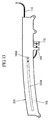
- Figs. 10, 11, 12, and 13 are a front elevation view, plan view, bottom view, and rear side elevation view, respectively.
- a long hole 103A through which a central axis 105A of the roller 105 is inserted, such that the roller 105 is moved along the long hole 103A while rotating.
- a stationary portion 106 is formed in an upper side of the opening of the lower case 103.
- the power supply line 110 is secured to the stationary portion 106 (one of portions marked by "X" in Figs. 15 and 16).
- a frame member 103B in which the compression spring 104 is housed to thereby maintain accuracy during a telescopic motion of the compression spring 104.
- the compression spring 104 may be a plate spring or other similar spring known in the art.
- the compression spring 104 is made of metal, whereas the lower case 103 and the roller 105 are made of synthetic resin, or other such substance known in the art.
- Fig. 14 is a perspective view illustrating the lower case 103 with the upper case 102 secured in a cap manner thereto.
- the stationary portion 106 for holding the power supply line 110 is formed of the upper case 102 and the lower case 103.
- the state illustrated in Figs. 9 through 14 is a state in which the sliding door 111 is in a fully opened state and in which the compression spring 104 is compressed to the full extent by the roller 105.
- a force that urges the roller 105 with respect to the compression spring 104 is a pulling force developed by the power supply line 110 pulling the roller 105 toward the one end thereof.
- Fig. 15 is a view to explain the sliding door 111 being in a fully closed state.
- illustration of the upper case 102 and the lower case 103 is omitted, in view of the ease of understanding movements of the roller 105 and the compression spring 104.
- It is a state in which the compression spring 104 is expanded such that the roller 105 is pressed onto the other end side of the inside of the case 103, and an amount or length by which the power supply line 110 has been drawn out at a sliding door 111 side of the case 103 is small.
- the power supply line protector 101 which encloses the compression spring 104 and the roller 105, is disposed underneath a doorstep 112 of the vehicle body.
- portions marked by "X" indicate portions at which the power supply line 110 has been secured or fixed.
- rollers 114 are secured to the sliding door 111 through a door arm 113 and run on a side surface of the doorstep 112.
- Fig. 16 is a view illustrating the sliding door 111 being in a fully opened state.
- the one end side of the power supply line 110 is drawn out of the case 103 in response to sliding movement of the sliding door 111.
- the roller 105 is moved or runs from left to right (in the figure) to thereby compress the compression spring 104.
- a reference numeral 115 indicates a connector of a harness extended from the power supply
- a reference numeral 116 indicates a connector of a harness extended from an appliance in the sliding door 111, both connectors being connected to respective ends of the power supply line 110.
- portions marked by "X" indicate portions at which the power supply line is secured.
- the roller 105 maintains a constant bending motion or behavior of the power supply line 110 such that breakage caused by having been bent at an acute angle is prevented.
- the compression spring 104 returns to an original, or initial position, when the sliding door 111 is closed.
- the power supply line portion between the two points urges the compression spring 104 via the roller 105 whereby the compression spring 104 is compressed and received in the frame 103A.
Landscapes
- Engineering & Computer Science (AREA)
- Mechanical Engineering (AREA)
- Electric Cable Arrangement Between Relatively Moving Parts (AREA)
- Power-Operated Mechanisms For Wings (AREA)
Abstract
Description
- Devices, systems, and methods consistent with the invention relate to a power supply apparatus for a sliding door in a motor vehicle such as a minivan (a so-called one-box car), wherein the sliding door and a vehicle body are electrically coupled to one another via a power supply line in order to regularly supply electrical power to the sliding door.
- Heretofore, in a sliding door of a motor vehicle such as a minivan, a structure has been known in which a power supply line is laid extending from a vehicle body to the sliding door in order to regularly supply electrical power and electrical signals to devices such as electric appliances in the sliding door. The power supply line is housed in a protector, which is made of plastic and installed in the sliding door, in a manner such that the power supply line is in a bending state inside the protector in order that expansion and contraction of the power supply line due to opening and closing movement of the sliding door can be absorbed or compensated.
- For example, a structure in which a protector has a slit-shaped opening along which a flanged guide portion whose longitudinal cross section has a curved-shape or slanted-shape is formed, in which a power supply line guidance portion is formed on the edge of the flanged guide portion, and is gradually curved or slanted in the height-wise direction, and in which an opening portion for leading out a power supply line is formed adjacent to the power supply line guidance portion such that it is connected to the slit-shaped opening is known from
Japanese Unexamined Patent Application, First Publication No. 2003-335188 - With this structure or apparatus, when a protector is secured to a sliding door and a power supply line is drawn out through a slit-shaped opening to a vehicle body side, the power supply line oscillates along the flanged guide portion at a time of opening and closing the sliding door, and smoothly climbs from an end of the slit-shaped opening along the power supply line guidance portion. Therefore, if a power supply line stationary portion at a vehicle body side is located at a position higher than the slit-shaped opening, an opening portion for guiding the power supply line has the same level of height as the power supply line stationary portion when the sliding door is, for example, fully closed. The power supply line is never folded in a U-turn manner with a small diameter in the vertical direction, and therefore, application of excessive bending force to the power supply line can be avoided.
- Further, when the sliding door is opened, the power supply line is caught by the power supply line guidance portion and smoothly guided by the flanged guide portion without being tangled. At the same time, the power supply line being drawn out through the slit-shaped opening is rendered curved or slanted and then smoothly bent in the height-wise direction. When the sliding door is fully closed, the sliding door is substantially outwardly separated from the vehicle body. Thus, a bending radius along the flanged guide portion becomes large such that application of excessive bending force to the power supply line can be avoided.
- One conventional protector is formed relatively large in a snail-shape in order to prevent the power supply line from being repeatedly bent with a small diameter in a U-turn manner. Namely, the protector is relative large to form such a snail-shape. If such large protectors are used for production, disadvantages in terms of production costs are generated. In addition thereto, since such a large protector is incorporated inside the sliding door, the locations on which other appliances can be provided are limited, thus resulting in poor design in terms of the layout inside the door.
- In consideration of the above circumstances, an aspect of the present invention is to provide a power supply apparatus for a sliding door, enabling down-sizing, avoiding the detrimental influence caused by repeated bending, and easing a design of components layout inside the door.
- In accordance with a first aspect of the present invention, there is provided a power supply apparatus for a vehicular sliding door, the apparatus including a power supply line which is electrically connected to a power supply to supply electrical power to electrical appliances inside the sliding door; a power supply line protector which includes a rectangular-shaped case and is disposed in the sliding door and in which the power supply line is housed in a bent state; a power supply line path which is provided in the case of the power supply line protector and which controls the bent state of the power supply line; a slider which is received in, and slidable along a length of, the case; an extension spring by which the slider is normally urged toward one end side of the case; and a slit-shaped opening which is formed in an underside of the case and which covers a range of sliding of the slider; wherein a power supply side portion of the power supply line is drawn out through the opening of the case and then secured to a vehicle body side; and wherein a power supply line portion, which has been drawn out from another end side of the case, is connected to electrical appliances inside the sliding door.
- The slider may include a distal end member along the contour of which the power supply line is bent so that a power supply line portion from a power supply line path side to an upper side thereof is curved; a base end member to which the extension spring is connected; and a connecting member through which the distal end member and the base end member are connected.
- The power supply line in the case may be inserted in a sheath member.
- The extension spring may consist of a coil spring bent in a U-shape.
- The power supply line protector may be integrally formed with a module plate into which appliances to be disposed in the sliding door are incorporated.
- In accordance with a second aspect of the present invention, there is provided a power supply apparatus for a vehicular sliding door, the apparatus including a power supply line which is electrically connected to a power supply to supply electrical power to electrical appliances inside the sliding door; a power supply line protector which includes a rectangular-shaped case and is disposed in the sliding door and in which the power supply line is housed in a bent state; a compression spring a base end of which is secured to one end side of the inside of the case; and a roller which is disposed at a front end of the compression spring and which rolls within the case, the periphery of the roller being round; wherein the power supply line is extracted through the one end side of the case and through an opening of the case and then connected to the power supply, a partway portion of the power supply line being traversed over the roller in the case; wherein when the sliding door is in an opened state, the partway portion of the power supply line is extracted out of the case and the compression spring is compressed by the roller; and wherein the roller is pushed back due to a restoring force of the compression spring in response to sliding or closing movement of the sliding door.
- The compression spring may consist of a plate spring bent in a zigzag manner.
- As described above, if a module plate and a protector have been previously formed integrally with one another, installation operation for the inside of a door would further be expedited.
- The above and other aspects of the present invention will become apparent upon consideration of the following detailed description of exemplary embodiments thereof, particularly when taken in conjunction with the accompanying drawings wherein like reference numerals in the various figures are utilized to designate like components.
- The above and other aspects of the invention will become more apparent by describing in detail exemplary embodiments thereof with reference to the attached drawings in which:
- Fig. 1 is a perspective view illustrating portions of a first embodiment of the present invention.
- Fig. 2 is a perspective view of the portions shown in Fig. 1, with a cover secured thereto.
- Fig. 3 is a simplified view to explain operation of a power supply line protector when a sliding door is opened and closed.
- Fig. 4 is a simplified view illustrating the inside of the power supply line protector in a state in which the sliding door is closed.
- Fig. 5 is a simplified view illustrating the inside of the power supply line protector in a state in which the sliding door is opened.
- Fig. 6 is a diagrammatically schematic view illustrating a relationship between the power supply line protector and sliding movement of the sliding door.
- Fig. 7 is a perspective view illustrating a case formed integrally with a module plate.
- Fig. 8 is a perspective view illustrating the case of Fig. 7, with the cover secured thereto.
- Fig. 9 is a perspective view illustrating a power supply line protector of a second embodiment prior to securing an upper case thereto.
- Fig. 10 is a front elevation view of the power supply line protector.
- Fig. 11 is a plan view of the power supply line protector.
- Fig. 12 is a bottom plan view of the power supply line protector.
- Fig. 13 is a rear side elevation view of the power supply line protector.
- Fig. 14 is a perspective view illustrating the power supply line protector after securing the upper case thereto.
- Fig. 15 is a view to explain the sliding door in a closed state.
- Fig. 16 is a view to explain the sliding door in an opened state.
- Exemplary embodiments of the invention will now be described below by reference to the attached Figures. The described exemplary embodiments are intended to assist the understanding of the invention, and are not intended to limit the scope of the invention in any way.
Hereinafter, a first exemplary embodiment of a power supply apparatus for a sliding door in a motor vehicle according to the invention will be described with reference to Figs. 1 through 8. - As shown in Fig, 1, a power
supply line protector 1 includes a rectangular-shaped case 2 inside of which apower supply line 3 is housed in a curved or bent state to supply electrical power to electric appliances in the sliding door. A powersupply line path 5 is provided in thecase 2 to control bending of thepower supply line 3. Aslider 4 is provided in thecase 2 so as to slide along a lengthwise direction of thecase 2. Theslider 4 is comprised of adistal end member 6 having a rounded portion, a connecting member 7, and a base end member 8 that is connected to thedistal end member 6 through the connecting member 7. Thepower supply line 3 is guided by and curved along a surface (the contour) from a power supply path side to an upper side of the rounded portion of thedistal end member 6. The aforementioned connecting member 7 is a thin plate-shaped member and enables a sliding operation of theslider 4 in thecase 2. More specifically, the connecting member 7 of theslider 4 has upper and lower ends, which are fitted in respective rails or recesses (not shown in the drawings) such that theslider 4 is slidable along the rails. Theslider 4 is connected to anextension spring 9, which normally urges theslider 4 toward one end side of thecase 2. Thisextension spring 9 is inserted in a U-shapedprotective case 10 such that a coil spring constituting theextension spring 9 is generally curved so as to present a U-shaped configuration. Thisextension spring 9 has ends both of which are fixedly connected to the base end member 8 of theslider 4 such that theslider 4 is normally urged in a leftward direction in Fig. 1. In thecase 2, thepower supply line 3 is inserted in asheath member 11 for protection thereof. As thesheath member 11, a corrugated tube made of plastic resin, or other suitable material known in the art, can advantageously be used. One end of thepower supply line 3 or aportion 3A which is drawn out from the powersupply line path 5 through a below-mentionedopening 12 is fixed to a vehicle body for electrical connection to a power supply. Anotherportion 3B (or another end of the power supply line 3), which is drawn out through an opening 2A of another end of thecase 2, is connected to appliances inside the sliding door. A slit-shaped opening 12 whose dimension corresponds to a sliding length of theslider 4 is provided on the underside of thecase 2. Thesupply line 3 is moved or slid along theopening 12 while penetrating therethrough. - Fig. 2 illustrates a state in which a
cover 13 is secured to one side surface of thecase 2 of Fig. 1. As already described, in the state in which the side surface of thecase 2 is covered with thecover 13, thepower supply line 3 is drawn out through theopening 2A of the aforesaid another end of thecase 2 and then connected to the appliances inside the sliding door. Thepower supply line 3 is also drawn out through theopening 12 via the powersupply line path 5 and then fixed to the vehicle body (not shown) for electrical connection to the power supply. - Fig. 3 is a view to explain operation of the apparatus of the present exemplary embodiment when a sliding
door 20 is opened and closed. Thepower supply line 3 is secured to the vehicle body, and more specifically to a stepped portion thereof, and has aconnector 23 at its leading end. Theconnector 23 is connected to a wire harness which is extended from the power supply. When the slidingdoor 20 is positioned at a right side in Fig. 3, it is in a closed state. When the slidingdoor 20 is opened or slid leftward as indicated by an arrow on a dash-dot line, theslider 4 is pulled leftward against a tensioning force of theextension spring 9 in response to a sliding of the slidingdoor 20. - The fact that the
power supply line 3 is secured to avehicle body 21 by astationary portion 22 is part of the reason that theslider 4 is slid. When the slidingdoor 20 has reached a left side position of Fig. 3, it is in a fully open state. A length of thepower supply line 3 which extends from thestationary portion 22 to the powersupply line protector 1 becomes long. - Fig. 4 illustrates a simplified inner structure of the power
supply line protector 1 when the slidingdoor 20 is in a open state, or occupies a position shown at a left side in Fig. 3. Further, Fig. 5 illustrates the simplified inner structure of thepower supply protector 1 when the slidingdoor 20 is in a fully closed state. In the fully opened state, thepower supply line 3 in thecase 2 is drawn out through theopening 12 lengthily to the outside. In the fully closed state, a greater part of thepower supply line 3 is received in thecase 2. Fig. 6 is a view to explain a general concept of the slidingdoor 20 being slid from a closed state to an opened state. - As seen from Figs. 4 and 5, the
power supply line 3 is fixed to thevehicle body 21 by thestationary portion 22 at one end side (or theportion 3A) of thepower supply line 3. Thepower supply line 3 is positioned such that it follows the contour of thedistal end member 6 of theslider 4. The case 2 (the power supply protector 1) is slid along with the slidingdoor 20, and therefore, thepower supply line 3 causes theslide 4 to move. As thepower supply line 3, it is advantageous to use a wire harness having a circular cross-section rather than a wire harness having a flat shape, in terms of strength. Further, thesheath member 11 is advantageously formed in a cylindrical shape. Figs. 7 and 8 illustrate amodule plate 30 and thecase 2, both of which are integrally formed with one another and made of synthetic resin, the latter figure illustrating a state in which thecover 13 is secured to one side thereof. - Recently, in motor-vehicle manufacturing companies, with the aim of improving the ease of assembly, reducing costs by parts integration, and reducing weight, door modules have been adopted. A typical door module is structured by a module plate and by parts, i.e., a power window in a door, an actuator for self-locking, a regulator, and other parts known in the art, mounted on the module plate, wherein the module plate with the parts mounted thereon is installed in an opening formed in an inner panel of the door at the same time as one unit. When applying an apparatus according to exemplary embodiments of the present invention to a vehicle employing such a door module, a structure is formed in which a module plate and a case are injection-molded to be integrally formed with one another and in which a regular power supply line protector is integrated with a door module.
- Next, a second exemplary embodiment according to the present invention will be described hereinafter with reference to Figs. 9 through 16.
- Fig. 9 is a perspective view illustrating a power
supply line protector 101 to be incorporated in a vehicle body, without an upper case 102 (see Fig. 11). Acompression spring 104 is secured to one end of a lower case 103 (referred to simply as a "case") at a base end thereof. A circumferentiallycircular roller 105 is disposed at a leading end of thecompression spring 104 and rolls inside thelower case 103. An illustrated groove is formed on the periphery of theroller 105 so as to present a pulley wheel, along, or in which, apower supply line 110 can run. One end of thepower supply line 110, which has been drawn out of a right end, in Fig. 9, of thelower case 103, is connected to an appliance (not shown) in a slidingdoor 111, whereas the other end of thepower supply line 110 is drawn out at a lengthwise directional side of an opening, and then, connected to a power supply. - Figs. 10, 11, 12, and 13 are a front elevation view, plan view, bottom view, and rear side elevation view, respectively. In the
lower case 103 is formed along hole 103A, through which acentral axis 105A of theroller 105 is inserted, such that theroller 105 is moved along thelong hole 103A while rotating. Further, astationary portion 106 is formed in an upper side of the opening of thelower case 103. Thepower supply line 110 is secured to the stationary portion 106 (one of portions marked by "X" in Figs. 15 and 16). Further, in thelower case 103 is formed aframe member 103B in which thecompression spring 104 is housed to thereby maintain accuracy during a telescopic motion of thecompression spring 104. Thecompression spring 104 may be a plate spring or other similar spring known in the art. Thecompression spring 104 is made of metal, whereas thelower case 103 and theroller 105 are made of synthetic resin, or other such substance known in the art. Fig. 14 is a perspective view illustrating thelower case 103 with theupper case 102 secured in a cap manner thereto. Thestationary portion 106 for holding thepower supply line 110 is formed of theupper case 102 and thelower case 103. The state illustrated in Figs. 9 through 14 is a state in which the slidingdoor 111 is in a fully opened state and in which thecompression spring 104 is compressed to the full extent by theroller 105. A force that urges theroller 105 with respect to thecompression spring 104 is a pulling force developed by thepower supply line 110 pulling theroller 105 toward the one end thereof. - Fig. 15 is a view to explain the sliding
door 111 being in a fully closed state. In the Figure, illustration of theupper case 102 and thelower case 103 is omitted, in view of the ease of understanding movements of theroller 105 and thecompression spring 104. It is a state in which thecompression spring 104 is expanded such that theroller 105 is pressed onto the other end side of the inside of thecase 103, and an amount or length by which thepower supply line 110 has been drawn out at a slidingdoor 111 side of thecase 103 is small. The powersupply line protector 101, which encloses thecompression spring 104 and theroller 105, is disposed underneath adoorstep 112 of the vehicle body. In the figures, portions marked by "X" indicate portions at which thepower supply line 110 has been secured or fixed. Further,rollers 114 are secured to the slidingdoor 111 through adoor arm 113 and run on a side surface of thedoorstep 112. - Fig. 16 is a view illustrating the sliding
door 111 being in a fully opened state. The one end side of thepower supply line 110 is drawn out of thecase 103 in response to sliding movement of the slidingdoor 111. By the power supply line being drawn out, theroller 105 is moved or runs from left to right (in the figure) to thereby compress thecompression spring 104. Incidentally, areference numeral 115 indicates a connector of a harness extended from the power supply, and areference numeral 116 indicates a connector of a harness extended from an appliance in the slidingdoor 111, both connectors being connected to respective ends of thepower supply line 110. Moreover, in Figs. 15 and 16, portions marked by "X" indicate portions at which the power supply line is secured. - The
roller 105 maintains a constant bending motion or behavior of thepower supply line 110 such that breakage caused by having been bent at an acute angle is prevented. Thecompression spring 104 returns to an original, or initial position, when the slidingdoor 111 is closed. When the slidingdoor 111 is in an opened state, the power supply line portion between the two points ("X" marked portions in Figs. 15 and 16) urges thecompression spring 104 via theroller 105 whereby thecompression spring 104 is compressed and received in theframe 103A. - While the invention has been particularly shown and described with reference to exemplary embodiments thereof, the invention is not limited to these exemplary embodiments. It will be understood by those of ordinary skill in the art that various changes in form and details may be made therein without departing from the spirit and scope of the invention as defined by the following claims interpreted in light of the description and drawings.
Claims (7)
- A power supply apparatus for a vehicular sliding door, the apparatus comprising:a power supply line which is electrically coupled to a power supply to supply electrical power to electrical appliances inside the vehicular sliding door;a power supply line protector which includes a case and is disposed in the vehicular sliding door and in which the power supply line is housed in a bent state;a power supply line path which is provided in the case and which controls the bent state of the power supply line;a slider which is received in, and slidable along, a length of, the case;an extension spring by which the slider is urged toward one end side of the case; anda slit-shaped opening which is formed in an underside of the case and which covers a sliding range of the slider;wherein a power supply side portion of the power supply line is drawn out through the slit-shaped opening and secured to a vehicle body side; and
wherein a power supply line portion, which has been drawn out from another end side of the case, is connected to electrical appliances inside the sliding door. - The power supply apparatus according to claim 1, wherein the slider comprises:a distal end member along the contour of which the power supply line is bent so that a power supply line portion from a power supply line path side to an upper side thereof is curved;a base end member to which the extension spring is connected; anda connecting member through which the distal end member and the base end member are connected.
- The power supply apparatus according to claim 1, wherein the power supply line in the case is inserted in a sheath member.
- The power supply apparatus according to claim 1, wherein the extension spring consists of a coil spring bent in a U-shape.
- The power supply apparatus according to claim 1, wherein the power supply line protector is integrally formed with a module plate into which appliances to be disposed in the sliding door are incorporated.
- A power supply apparatus for a vehicular sliding door, the apparatus comprising:a power supply line which is electrically coupled to a power supply to supply electrical power to electrical appliances inside the vehicular sliding door;a power supply line protector which includes a case and is disposed in the sliding door and in which the power supply line is housed in a bent state;a compression spring, a base end of which is secured to one end side of an inside of the case; anda roller which is disposed at a front end of the compression spring and which rolls within the case, a periphery of the roller being round;wherein the power supply line is extracted through the one end side of the case and through an opening of the case and connected to the power supply, a partway portion of the power supply line being traversed over the roller;
wherein when the sliding door is in an opened state, the partway portion of the power supply line is extracted out of the case and the compression spring is compressed by the roller; and
wherein the roller is pushed back due to a restoring force of the compression spring in response to a closing movement of the sliding door. - The power supply apparatus according to claim 6, wherein the compression spring is a plate spring bent in a zigzag manner.
Applications Claiming Priority (2)
| Application Number | Priority Date | Filing Date | Title |
|---|---|---|---|
| JP2005095383A JP2006273120A (en) | 2005-03-29 | 2005-03-29 | Constant power supply device for sliding doors |
| JP2005141560A JP2006320145A (en) | 2005-05-13 | 2005-05-13 | Constant power supply device for sliding doors |
Publications (2)
| Publication Number | Publication Date |
|---|---|
| EP1707443A1 true EP1707443A1 (en) | 2006-10-04 |
| EP1707443B1 EP1707443B1 (en) | 2008-05-21 |
Family
ID=36603603
Family Applications (1)
| Application Number | Title | Priority Date | Filing Date |
|---|---|---|---|
| EP06251536A Expired - Lifetime EP1707443B1 (en) | 2005-03-29 | 2006-03-22 | Power supply apparatus for sliding door |
Country Status (5)
| Country | Link |
|---|---|
| US (1) | US7641260B2 (en) |
| EP (1) | EP1707443B1 (en) |
| KR (1) | KR100798828B1 (en) |
| CA (1) | CA2540456C (en) |
| DE (1) | DE602006001234D1 (en) |
Cited By (1)
| Publication number | Priority date | Publication date | Assignee | Title |
|---|---|---|---|---|
| EP3817167A1 (en) * | 2019-10-28 | 2021-05-05 | Hauff-Technik GmbH & Co. KG | Method for fixing an insulation to a wall |
Families Citing this family (7)
| Publication number | Priority date | Publication date | Assignee | Title |
|---|---|---|---|---|
| JP5052865B2 (en) * | 2006-11-13 | 2012-10-17 | 矢崎総業株式会社 | Power feeding device for slide structure |
| JP4913690B2 (en) * | 2007-07-27 | 2012-04-11 | 古河電気工業株式会社 | Power supply device for sliding door |
| JP4447633B2 (en) * | 2007-11-07 | 2010-04-07 | 三井金属鉱業株式会社 | Automatic opening / closing device for vehicle sliding door |
| WO2010024088A1 (en) * | 2008-08-29 | 2010-03-04 | 矢崎総業株式会社 | Wire harness routing structure |
| US8253074B2 (en) * | 2008-12-06 | 2012-08-28 | General Electric Company | Wiring assembly for an appliance |
| ES2325611A1 (en) * | 2009-04-03 | 2009-09-09 | Oscar Torrabias Cantal | Retroilumed sliding door (Machine-translation by Google Translate, not legally binding) |
| TWI574479B (en) * | 2015-11-23 | 2017-03-11 | 緯創資通股份有限公司 | Telescopic device having carrier member, carrier member and cable thereof |
Citations (8)
| Publication number | Priority date | Publication date | Assignee | Title |
|---|---|---|---|---|
| US3433889A (en) * | 1966-06-30 | 1969-03-18 | Bell Telephone Labor Inc | Reciprocating electric connecting system |
| EP0282389A1 (en) * | 1987-03-05 | 1988-09-14 | Peugeot Automobiles | Device for electrical connection between two bundles of conductive wires, and automotive car equipped with such a device |
| JPH11342807A (en) * | 1998-06-03 | 1999-12-14 | Yazaki Corp | Method for preventing sagging of flexible flat cable in power supply device for sliding door for automobile, and structure for preventing sagging of flexible flat cable |
| DE19835579A1 (en) * | 1998-08-06 | 2000-02-17 | Daimler Chrysler Ag | Cable and/or tube guiding device for motor vehicle |
| EP1108621A2 (en) * | 1999-12-14 | 2001-06-20 | Sumitomo Wiring Systems, Ltd. | Harness-wiring system for a sliding door of vehicles |
| US6492592B1 (en) * | 1999-01-12 | 2002-12-10 | Yazaki Corporation | Electricity supplying structure on motor vehicle sliding door |
| JP2003306089A (en) * | 2002-04-11 | 2003-10-28 | Yazaki Corp | Wire excess length absorption device and power supply device for sliding door using the same |
| JP2003335188A (en) | 2002-05-17 | 2003-11-25 | Yazaki Corp | Harness protector for power supply and harness wiring structure using it |
-
2006
- 2006-03-20 CA CA002540456A patent/CA2540456C/en not_active Expired - Fee Related
- 2006-03-22 EP EP06251536A patent/EP1707443B1/en not_active Expired - Lifetime
- 2006-03-22 DE DE602006001234T patent/DE602006001234D1/en not_active Expired - Lifetime
- 2006-03-23 KR KR1020060026604A patent/KR100798828B1/en not_active Expired - Fee Related
- 2006-03-23 US US11/386,760 patent/US7641260B2/en not_active Expired - Fee Related
Patent Citations (8)
| Publication number | Priority date | Publication date | Assignee | Title |
|---|---|---|---|---|
| US3433889A (en) * | 1966-06-30 | 1969-03-18 | Bell Telephone Labor Inc | Reciprocating electric connecting system |
| EP0282389A1 (en) * | 1987-03-05 | 1988-09-14 | Peugeot Automobiles | Device for electrical connection between two bundles of conductive wires, and automotive car equipped with such a device |
| JPH11342807A (en) * | 1998-06-03 | 1999-12-14 | Yazaki Corp | Method for preventing sagging of flexible flat cable in power supply device for sliding door for automobile, and structure for preventing sagging of flexible flat cable |
| DE19835579A1 (en) * | 1998-08-06 | 2000-02-17 | Daimler Chrysler Ag | Cable and/or tube guiding device for motor vehicle |
| US6492592B1 (en) * | 1999-01-12 | 2002-12-10 | Yazaki Corporation | Electricity supplying structure on motor vehicle sliding door |
| EP1108621A2 (en) * | 1999-12-14 | 2001-06-20 | Sumitomo Wiring Systems, Ltd. | Harness-wiring system for a sliding door of vehicles |
| JP2003306089A (en) * | 2002-04-11 | 2003-10-28 | Yazaki Corp | Wire excess length absorption device and power supply device for sliding door using the same |
| JP2003335188A (en) | 2002-05-17 | 2003-11-25 | Yazaki Corp | Harness protector for power supply and harness wiring structure using it |
Non-Patent Citations (2)
| Title |
|---|
| PATENT ABSTRACTS OF JAPAN vol. 2000, no. 03 30 March 2000 (2000-03-30) * |
| PATENT ABSTRACTS OF JAPAN vol. 2003, no. 12 5 December 2003 (2003-12-05) * |
Cited By (1)
| Publication number | Priority date | Publication date | Assignee | Title |
|---|---|---|---|---|
| EP3817167A1 (en) * | 2019-10-28 | 2021-05-05 | Hauff-Technik GmbH & Co. KG | Method for fixing an insulation to a wall |
Also Published As
| Publication number | Publication date |
|---|---|
| HK1091788A1 (en) | 2007-01-26 |
| KR20060105457A (en) | 2006-10-11 |
| US20060219711A1 (en) | 2006-10-05 |
| KR100798828B1 (en) | 2008-01-28 |
| US7641260B2 (en) | 2010-01-05 |
| DE602006001234D1 (en) | 2008-07-03 |
| EP1707443B1 (en) | 2008-05-21 |
| CA2540456C (en) | 2009-07-21 |
| CA2540456A1 (en) | 2006-09-29 |
Similar Documents
| Publication | Publication Date | Title |
|---|---|---|
| US6515229B2 (en) | Structure of installing wire harness for sliding door | |
| JP4149245B2 (en) | Power feeding device and harness wiring structure using the same | |
| EP1544046B1 (en) | Structure for installing a door harness | |
| JP4560478B2 (en) | Power feeding device for slide structure | |
| CN104508929B (en) | Sliding door electric power-feeding structure | |
| CN110945730B (en) | Wire harness routing device | |
| JP4746965B2 (en) | Power feeding device for slide structure | |
| JP2010016939A (en) | Electric power supplying device and harness routing structure using the same | |
| US7683259B2 (en) | Power supply system | |
| CN102138262A (en) | Wire harness routing structure | |
| JP5322539B2 (en) | Wiring harness wiring structure | |
| CA2540456C (en) | Power supply apparatus for sliding door | |
| US20070158108A1 (en) | Power-supplying apparatus for sliding structure | |
| JP4256764B2 (en) | Harness guide protector, wire surplus length absorption structure including the same, and harness guide protector fixing method | |
| CN1841872B (en) | Power supply apparatus for sliding door | |
| JP4021603B2 (en) | Routing structure for sliding door harness | |
| JP4077276B2 (en) | Power supply device for sliding door | |
| JP3940315B2 (en) | Harness protector for power feeding and harness routing structure using it | |
| JP2001128350A (en) | Flat cable winder | |
| HK1091788B (en) | Power supply apparatus for sliding door | |
| JP4180992B2 (en) | Wire surplus length absorber | |
| JP4205611B2 (en) | Power supply device for sliding door | |
| JP2006320145A (en) | Constant power supply device for sliding doors | |
| JP5294390B2 (en) | Wiring harness wiring structure | |
| JP5052032B2 (en) | Wiring harness wiring structure |
Legal Events
| Date | Code | Title | Description |
|---|---|---|---|
| PUAI | Public reference made under article 153(3) epc to a published international application that has entered the european phase |
Free format text: ORIGINAL CODE: 0009012 |
|
| 17P | Request for examination filed |
Effective date: 20060329 |
|
| AK | Designated contracting states |
Kind code of ref document: A1 Designated state(s): AT BE BG CH CY CZ DE DK EE ES FI FR GB GR HU IE IS IT LI LT LU LV MC NL PL PT RO SE SI SK TR |
|
| AX | Request for extension of the european patent |
Extension state: AL BA HR MK YU |
|
| REG | Reference to a national code |
Ref country code: HK Ref legal event code: DE Ref document number: 1091788 Country of ref document: HK |
|
| 17Q | First examination report despatched |
Effective date: 20070116 |
|
| AKX | Designation fees paid |
Designated state(s): DE FR GB IT SE |
|
| GRAP | Despatch of communication of intention to grant a patent |
Free format text: ORIGINAL CODE: EPIDOSNIGR1 |
|
| GRAS | Grant fee paid |
Free format text: ORIGINAL CODE: EPIDOSNIGR3 |
|
| GRAA | (expected) grant |
Free format text: ORIGINAL CODE: 0009210 |
|
| AK | Designated contracting states |
Kind code of ref document: B1 Designated state(s): DE FR GB IT SE |
|
| REG | Reference to a national code |
Ref country code: GB Ref legal event code: FG4D |
|
| REF | Corresponds to: |
Ref document number: 602006001234 Country of ref document: DE Date of ref document: 20080703 Kind code of ref document: P |
|
| REG | Reference to a national code |
Ref country code: SE Ref legal event code: TRGR |
|
| REG | Reference to a national code |
Ref country code: HK Ref legal event code: GR Ref document number: 1091788 Country of ref document: HK |
|
| PLBE | No opposition filed within time limit |
Free format text: ORIGINAL CODE: 0009261 |
|
| STAA | Information on the status of an ep patent application or granted ep patent |
Free format text: STATUS: NO OPPOSITION FILED WITHIN TIME LIMIT |
|
| 26N | No opposition filed |
Effective date: 20090224 |
|
| PGFP | Annual fee paid to national office [announced via postgrant information from national office to epo] |
Ref country code: IT Payment date: 20120317 Year of fee payment: 7 Ref country code: SE Payment date: 20120313 Year of fee payment: 7 |
|
| PGFP | Annual fee paid to national office [announced via postgrant information from national office to epo] |
Ref country code: GB Payment date: 20130320 Year of fee payment: 8 Ref country code: FR Payment date: 20130325 Year of fee payment: 8 Ref country code: DE Payment date: 20130320 Year of fee payment: 8 |
|
| REG | Reference to a national code |
Ref country code: SE Ref legal event code: EUG |
|
| PG25 | Lapsed in a contracting state [announced via postgrant information from national office to epo] |
Ref country code: SE Free format text: LAPSE BECAUSE OF NON-PAYMENT OF DUE FEES Effective date: 20130323 |
|
| PG25 | Lapsed in a contracting state [announced via postgrant information from national office to epo] |
Ref country code: IT Free format text: LAPSE BECAUSE OF NON-PAYMENT OF DUE FEES Effective date: 20130322 |
|
| REG | Reference to a national code |
Ref country code: DE Ref legal event code: R119 Ref document number: 602006001234 Country of ref document: DE |
|
| GBPC | Gb: european patent ceased through non-payment of renewal fee |
Effective date: 20140322 |
|
| REG | Reference to a national code |
Ref country code: FR Ref legal event code: ST Effective date: 20141128 |
|
| REG | Reference to a national code |
Ref country code: DE Ref legal event code: R119 Ref document number: 602006001234 Country of ref document: DE Effective date: 20141001 |
|
| PG25 | Lapsed in a contracting state [announced via postgrant information from national office to epo] |
Ref country code: GB Free format text: LAPSE BECAUSE OF NON-PAYMENT OF DUE FEES Effective date: 20140322 Ref country code: FR Free format text: LAPSE BECAUSE OF NON-PAYMENT OF DUE FEES Effective date: 20140331 Ref country code: DE Free format text: LAPSE BECAUSE OF NON-PAYMENT OF DUE FEES Effective date: 20141001 |