EP1544046B1 - Structure for installing a door harness - Google Patents
Structure for installing a door harness Download PDFInfo
- Publication number
- EP1544046B1 EP1544046B1 EP04293006A EP04293006A EP1544046B1 EP 1544046 B1 EP1544046 B1 EP 1544046B1 EP 04293006 A EP04293006 A EP 04293006A EP 04293006 A EP04293006 A EP 04293006A EP 1544046 B1 EP1544046 B1 EP 1544046B1
- Authority
- EP
- European Patent Office
- Prior art keywords
- door
- harness
- panel
- grommet
- door harness
- Prior art date
- Legal status (The legal status is an assumption and is not a legal conclusion. Google has not performed a legal analysis and makes no representation as to the accuracy of the status listed.)
- Expired - Fee Related
Links
Images


Classifications
-
- B—PERFORMING OPERATIONS; TRANSPORTING
- B60—VEHICLES IN GENERAL
- B60R—VEHICLES, VEHICLE FITTINGS, OR VEHICLE PARTS, NOT OTHERWISE PROVIDED FOR
- B60R16/00—Electric or fluid circuits specially adapted for vehicles and not otherwise provided for; Arrangement of elements of electric or fluid circuits specially adapted for vehicles and not otherwise provided for
- B60R16/02—Electric or fluid circuits specially adapted for vehicles and not otherwise provided for; Arrangement of elements of electric or fluid circuits specially adapted for vehicles and not otherwise provided for electric constitutive elements
- B60R16/0207—Wire harnesses
- B60R16/0215—Protecting, fastening and routing means therefor
Definitions
- the present invention relates to a structure or system for wiring a door harness in a vehicle and, in particular, to a structure or system in which the door harness is wired from the door inner panel to the body panel.
- the door harness is thus no longer pulled out towards the vehicle body through a hole provided in the edge face of the door panel adjacent to the vehicle's body panel.
- Document US 5 884 961 discloses a door wire harness arrangement structure.
- a wire harness is taken into a wire harness protector case, with a part of it being folded like a ring.
- the ring-like portion of the wire harness can freely expand and contract inside the wire harness protector case.
- a wire harness support pin stands inside the wire harness protector case, which is provided with a circular or semicircular wire harness receiving portion.
- Document EP 0 855 312 discloses a wiring harness arrangement in a position more toward a passenger compartment than a hinge and weatherstrip.
- a container casing is comprised of a space for accommodating a looped harness, an insertion opening and a withdrawal opening for the harness which are opposed to each other, and a harness fixing portion projecting from the outer surface of the insertion opening. After being inserted through the insertion opening and wound around a windup spring inside the casing, the wiring harness is withdrawn trough the withdrawal opening.
- the container casing is secured to either one of a door and a body, and the wiring harness withdrawn from the container casing is extended to the other of the door and the body and secured thereto by a clamp.
- Document EP 1 241 056 discloses a harness slack absorbing apparatus including a resilient member, a harness support member attached to a distal end portion of the resilient member, and a wire harness supported by the harness support member and pushed upward by resilience of the resilient member thereby to absorb a slack of the wire harness.
- the harness support member includes a recess having a curved shape in cross section, in which the wire harness is held.
- the harness support member may be provided at its distal end with a curved or inclined face which is continued from the recess in a shape along a bending direction of the wire harness.
- Document US 5 556 059 discloses a device for guiding a wire harness connected to a steering column and including a protector for accommodating a slacken part of the wire harness therein and two half cylindrical ribs elastically formed in the protector. In operation, when the slacken part is expanded, the ribs serve to urge the slacken part to recover the original configuration before being expanded.
- Document EP 1 236 599 discloses a door module panel initially mounted with a door harness and provided with a panel hole at a position where a descending window glass does not interfere.
- the door harness is wired from a first surface facing a passenger compartment of the door module panel to a second surface facing a door frame through the panel hole.
- the door module panel has a side face, from a middle portion of which a salient member is extended and bent towards the door frame.
- the salient member comprises a harness hole, through which is passed the door harness extending from the second surface of the door module panel.
- the door harness is then fitted into the harness hole with a grommet.
- Document US 6 092 859 discloses an arrangement of a door harness for a vehicle, having a slide guide arranged within a vehicle door, a harness protector slidably fit in the slideguide, a door harness introduced from the one end of the harness protector, and a body harness extending from a vehicle body coupled with the door harness.
- the harness protector is formed of soft resin and is secured to a front pillar of the vehicle body through a protector holder. Thus, when the door is opened or closed, the harness protector itself bends.
- a door harness used in a vehicle had to be drawn out from inside the door inner panel towards the body panel through a hole provided in the edge face of the door inner panel adjacent the body panel, and then connected to a wire harness in the body panel.
- the door harness is pulled out from inside the door inner panel, it is not possible to control the wiring operations visually thereon. Also, a strong force is required during this wiring operation. Hence, harness-passing operations are considered as difficult tasks.
- patent document JP-A-HEI-11-20573 discloses a door-harness wiring system using a "pass-work-less" grommet (duct) 1, as shown in Figs.1A and 1B.
- This particular "pass-work-less" grommet (or duct) 1 comprises a cylindrical bellows portion 2 through which the wire harness W is passed by pulling out from the door inner panel D.
- the grommet 1 further comprises a flat fitting plate 3 bent into an L shape.
- the fitting plate 3 covers the corner section formed at the edge face of the door inner panel D, and the wire harness W is made to run along the internal face of the fitting plate 3.
- the wire harness wired in this manner is then covered by a protection plate 4 fitted from inside the door inner panel D.
- Such a construction makes it unnecessary to pull out the wire harness W from the hole formed in the door inner panel D. Instead, the wire harness W is wired along the internal face of the door inner panel D toward its edge face, via its corner section, and led out toward the body panel B.
- the wire harness W can thus be wired by changing the level (upward or downward) at the fulcrum line in the hinge arrangement between the door and the vehicle body. Hence, upon opening or closing the door, the wire harness W is merely twisted, but neither stretched nor squashed.
- a weather strip 5, shown in Fig.1B must be mounted in a way to cross on the surface of the grommet 1 and door inner panel D.
- the fitting plate 3 and the protector sheet 4 should be composed of a specific resin-made product, and the wire harness W and the grommet 1 must be provided with a special water-sealing structure.
- Such newly-designed products will increase the number of component parts and harness-mounting steps and, consequently, costs.
- the weather strip 5 is mounted in a manner to avoid passing over the area of the grommet 1, e.g. by having the door harness installed closer to the passenger compartment relative to the weather strip.
- the wiring route of the door harness then becomes biased from the hinge arrangement between the door and the vehicle body, toward the passenger compartment, and the door harness has to be twisted, as well as stretched or squashed.
- JP-A-HEI 10-181479 of the present applicant proposes a structure shown in Fig.2A and 2B, in which a guide frame 6 having a triangular shape is mounted on either the door or the vehicle body.
- the wire harness is contained in this guide frame 6, with the excess length looped and wired toward the counterpart door or body. In this manner, the wire harness W can be pulled out from the guide frame 6 and stretched or squashed.
- the guide frame 6 has an insertion opening 6a and an exit opening 6b. After the wire harness W is passed through the guide frame 6, the part of harness placed adjacent the insertion opening 6a is fixed thereto with tape 9. The wire harness W follows a turn in the guide frame 6 so as to form a folded portion 7, and pulled out from the exit opening 6b. The inner side of the folded portion 7 is flanked by a spring plate 8 having e.g. a V-shaped cross-section, so that, when the door is closed, the wire harness W is drawn back into the guide frame 6 by the return force of the spring plate 8.
- a spring plate 8 having e.g. a V-shaped cross-section
- the above structure still has a drawback in that it requires a special component part, i.e. a guide frame 6 or the like.
- the present invention provides a structure for mounting a door harness, in which the door harness is placed closer to the car's compartment relative to the weather strip.
- Such structure allows the number of component parts to be reduced and the load to the door harness to be lowered
- the door harness by stretching or squashing (or expanding or compressing) the door harness, the latter can be passed in the area located closer to the car's compartment, i.e. farther from the fulcrum (pivot) line of the hinge arrangement, with respect to the weather strip. Accordingly, it becomes unnecessary to take the countermeasures hitherto called for in the prior art, such as flattening the grommet (duct) and door harness, providing special component parts for this purpose, installing a special water-sealing structure, etc.. Furthermore, the structure of the invention provides means to completely protect the wire harness and the compartment from water infiltration.
- the door harness is separated into two parts, both parts being fixed to the respective expandable/compressible guide members, which are disposed face to face e.g. in the height direction of the door.
- the stretching and squashing movement is rendered easier than when the door harness is grouped in one bundle.
- the loads imparted to each door harness by the above movements are lowered, and breakage of the wire harness can be prevented.
- the door harness can follow smoothly the opening or closing movements of the door, and the pair of expandable/compressible guide members are prevented from going away and taking up precious space.
- the expandable/compressible guide members can be implemented in a compact space.
- the expandable/compressible guide members are fixed to the grommet by fixing means, e.g. a tie band, they are securely prevented from deviating from the grommet during the stretching or squashing operation.
- fixing means e.g. a tie band
- the door harness separated into two parts can be stretched or squashed together with the corresponding spring portions of the expandable/compressible guide members.
- the door harness can smoothly follow the door's opening or closing movement.
- the grommet and the harness require no special water-sealing structure. There is also no need to prepare a flattened grommet and door harness, or particular component parts for that purpose. Hence, the water sealability is further enhanced.
- the door harness when the grommet (duct) hitherto used to connect the door harness to the hinge arrangement between the door and the car body is replaced by the elastic portion comprising a looped section and a spring member, the door harness can be stretched or shrunk depending on the opening or closing of the door. In this manner, the door harness can be passed closer to the compartment of the vehicle than is the weather strip, i.e. farther from the fulcrum point of the hinge arrangement. As a result, it is no longer necessary to flatten the grommet and door harness, or to prepare component parts specially for that purpose, or to provide special water-sealing means. Accordingly, while mounting the door harness in the proximity of the hinge arrangement, the number of component parts and mounting steps can be reduced, and costs can be lowered.
- the spring member is integrally formed with the grommet used in the door-harness mounting zone of the hinge arrangement, and the excess length portion of wire harness previously looped can be stretched or squashed in response to the stretching or squashing movement of the spring member.
- the door harness can smoothly follow the opening or closing movement of the door.
- the grommet and the wire harness require no special water-sealing structure. There is also no need to prepare a flattened grommet and door harness or particular parts for that purpose. Hence, the water sealability is further enhanced. Further, the number of component parts and assembly steps can be reduced, as well as the costs.
- the internal face 11a of the door inner panel 11 is provided with a fitting portion, e.g. recessed portion 12.
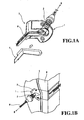
- the corner portion formed by the internal face 11a and the edge face 11b is provided with a grooved (indented) portion 15.
- a weather strip 18 is mounted along a mount line traced on the edge face 11b of the door inner panel 11.
- the grooved portion 15 has a half-open base 15a that extends from the edge face of the door inner panel 11, parallel to the internal face thereof. This half-open base 15a is placed at the side of the passenger compartment, seen from the mount line of the weather strip 18.
- the door inner panel 11 is flanked from the outside of the vehicle by a metal door outer panel 14.
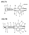
- the end portion of the door harness 20 is fitted with a grommet or duct or sheath 25 that comprises a bellows portion 26 e.g. in a cylindrical form.
- a first end portion of the grommet 25 is provided with a connector housing 28 containing a connector 21 (Fig.7B), whereas a second end portion of the grommet is provided with elastic means, e.g. a pair of expandable/compressible guide members 30 attached by fixing means e.g. a tie band 36.
- the grommet 25 is made of rubber or an elastomer.
- the connector housing 28 retains within its internal structure part of an inner frame 29 made of resin.
- the projecting part of the inner frame 29 is provided with e.g. a pair of protuberances 29a to engage with the car body.
- the pair of expandable/compressible guide members 30 (30A and 30B) is formed of a resin.
- Each guide member 30A comprises, at its central zone, elastic portions, e.g. spring portions 31, in the form of a semicircular arch.
- a grommet-fixing portion 35 having a flat shape extends from a first end of the elastic portions 31, and a panel-fixing portion 32 having a flat shape extends from a second end of the elastic portions 31.
- the panel-fixing portion 32 is further provided with a clipping portion 32a with a clip hole 32b (Figs. 8A, 8B).
- the expandable/compressible guide members 30 each comprise grooves 33 at their confronting internal faces and extending therealong. These grooves 33 define a C-shaped or U-shaped cross-section along the inside of which the door harness 20 is fitted.
- both ends of each of the elastic portions 31 are interconnected by a link member 34 e.g. in the form of X.
- the link member 34 connects: the confronting ends of the respective guide members 30A, 30B, for each of their ends, thereby forming top-bottom links, and the respective ends of each of the guide members, thereby forming longitudinal links (or left-right link in the figure).
- the door harness 20 is separated into two parts 20A and 20B, which are respectively held by the corresponding groove 33. As shown in Fig.7A, the two parts of door harness 20A and 20B are assembled into one section and led into the grommet 25.
- the grommet-fixing members 35 of the expandable/compressible guide members 30A and 30B are superposed on the second ends of the bellows portion 26 (e.g. in a cylindrical form) of the grommet 25, and fixed by the tie band 36.
- the grommet 25 is passed through the grooved portion 15 in the door inner panel 11 (Fig.3), and pulled toward the body panel 16.
- the resin protuberances 29a of the inner frame 29 are then inserted into the hole 16a of the body panel 16 and held therein, whilst the connector 21 at the first end of the grommet 25 is connected to another harness provided at the body side of the car.
- the door harness 20 and the second end of the pair of expandable/compressible guide members 30 are fixed to the compartment side of the mounting panel 13 by fitting a clip 40 through the clip hole 32b in the panel-fixing portion 32, into the mounting hole 13a in the mounting panel 13.
- the mounting panel 13 is then engaged with the door inner panel 11 through the fixing means 12 thereof.
- the compartment side of the resin panel 13 is mounted with trimming means, so as to cover the exposed portion of the door harness 20.
- the wiring path of the door harness 20 is located closer to the compartment side than is the weather strip 18.
- the door harness 20 is located closer to the compartment side than is the hinge arrangement 19 binding the door inner panel 11 to the body panel 16. Accordingly, when the door is opened or closed, the door harness is twisted or stretched or squashed.
- the elastic portions 31 of the expandable/compressible guide members 30 are stretched together with the door harness 20, when the door is opened (see Fig.8A), whereas the elastic portions 31 are compressed and restored with the help of the link member 34, when the door is closed (see Fig.8B). Accordingly, the length of the door harness 20 exiting from the grooved portion 15 can be adjusted.
- the door harness 20 and the grommet 25 placed near the hinge arrangement 19 can follow smoothly the movement of the door, and the opening and shutting operations are facilitated. Further, since the door harness 20 is placed closer to the inside compartment than the weather strip 18 is, it is no longer necessary to flatten the door harness 20 and the grommet 25, or to specifically provide water-sealing means in order to secure high water sealability.
- the X-shaped linking member in the expandable/compressible guide members 30 is not necessarily required.
- the elastic portions in the form of a semicircular arch may be replaced by one or several curved flat plate(s). In that case, each of door harness halves 20A and 20B is arranged along the flat plates and held by tape.
- the expandable/compressible guide members may be fixed to the grommet, instead of the tie band, by any suitable linking member that does not deflect from the grommet when the above guide member is stretched or compressed.
- the end portion of the door harness 20 is fitted with a grommet 25 and connected to a connector.
- the grommet 25 is made of rubber or an elastomer and integrates an elastic portion as in the first embodiment.
- the elastic portion comprises, going from the door side to the car's body side: a comparatively long looped section 41 having a cylindrical shape through which the door harness is passed, a comparatively short spring member 27 which binds both ends of the looped section 41 by forming a straight-line path between the ends, so maintaining the loop configuration, a bellows portion 26 e.g. having cylindrical shape, and a connector housing 28.
- the looping part 41a defined by the spring member 27 is passed through by the excess length portion 20a of the door harness such that the door harness 20 can expand or contract.
- the spring member 27 is in the form of a band having a rectangular cross-section, and is highly expandable and compressible. Further, as shown in Fig.6, an inner frame 29 e.g. made of resin is provided so as to project partly from the connector housing 28. This projecting portion comprises e.g. a pair of protuberances 29a with which the body panel is engaged.
- end portion of the looped section 41 that is distal from the connector housing 28, where the spring member 27 is engaged integrates a panel fixing portion 32 with a clip-fastening hole 32b.
- the mounting panel 13 is also provided with mounting hole 13a (Fig.10).
- the door harness 20 mounted with the grommet 25 passed on the internal face 11a of the door inner panel 11 and pulled out toward the body panel 16, such that the bellows portion 26 of the grommet 25 is installed in the grooved portion 15.
- the connector 21 of the pulled-out door harness 20 is then connected to a harness in the body panel 16 through a hole 16a formed therein, such that the protuberances 29a of the inner frame 29 mounted with the grommet 25 is engaged with the hole 16a.
- the end portion of the grommet 25 distal from the connector housing 28, together with the door harness 20, are bound to the surface of the mounting panel 13 facing the compartment of the vehicle, by inserting a clip 40 into the mounting hole 13a of the mounting panel 13 and the clip-fastening hole 32b in the panel-fixing portion 32 of the grommet 25 (Figs.9 and 10).
- the mounting panel 13 is then fitted into the recessed portion 12 in the door inner panel 11.
- the exposed portion of the door harness 20 is covered with a trim.
- the wiring path of the door harness 20 is located, compared to weather strip 18, closer to the passenger compartment.
- the door harness 20 is located more closely to the compartment, compared to the hinge arrangement 19 binding the door inner panel 11 to the body panel 16. Accordingly, when the door is opened or closed, the door harness is twisted, stretched or compressed. However, the spring portion 27 of the grommet 25 is stretched together with the door harness 20, when the door is opened (see Fig.12A), and conversely the spring portion 27 is shrunk and restored, when the door is closed (see Fig.12B). In this way, the length of the door harness 20 exiting from the grooved portion 15 can be regulated.
- the door harness 20 and the grommet 25 placed near the hinge arrangement 19 can follow smoothly the movement of the door, and the opening and shutting operations are improved. Further, since the door harness 20 is placed closer to the inside compartment than the weather strip 18 is, it is no longer necessary to flatten the door harness 20 and the grommet 25, or to specifically provide water-sealing means in order to secure high water sealability.
- the spring portion can be means other than the band having a rectangular cross-section. As far as the means are expandable and contractable, they may be a tube or a round cable.
- the grommet (duct or sheath) 25 may be formed of an elastomer. Further, the panel-fixing portion 32 of the grommet 25 may be configured so that it can be fixed to the internal base of the recessed portion 12 of the door inner panel 11.
Description
- The present invention relates to a structure or system for wiring a door harness in a vehicle and, in particular, to a structure or system in which the door harness is wired from the door inner panel to the body panel. The door harness is thus no longer pulled out towards the vehicle body through a hole provided in the edge face of the door panel adjacent to the vehicle's body panel.
- Document US 5 884 961 discloses a door wire harness arrangement structure. In this structure, a wire harness is taken into a wire harness protector case, with a part of it being folded like a ring. The ring-like portion of the wire harness can freely expand and contract inside the wire harness protector case. A wire harness support pin stands inside the wire harness protector case, which is provided with a circular or semicircular wire harness receiving portion.
- Document EP 0 855 312 discloses a wiring harness arrangement in a position more toward a passenger compartment than a hinge and weatherstrip. A container casing is comprised of a space for accommodating a looped harness, an insertion opening and a withdrawal opening for the harness which are opposed to each other, and a harness fixing portion projecting from the outer surface of the insertion opening. After being inserted through the insertion opening and wound around a windup spring inside the casing, the wiring harness is withdrawn trough the withdrawal opening. The container casing is secured to either one of a door and a body, and the wiring harness withdrawn from the container casing is extended to the other of the door and the body and secured thereto by a clamp.
-
Document EP 1 241 056 discloses a harness slack absorbing apparatus including a resilient member, a harness support member attached to a distal end portion of the resilient member, and a wire harness supported by the harness support member and pushed upward by resilience of the resilient member thereby to absorb a slack of the wire harness. The harness support member includes a recess having a curved shape in cross section, in which the wire harness is held. The harness support member may be provided at its distal end with a curved or inclined face which is continued from the recess in a shape along a bending direction of the wire harness. - Document US 5 556 059 discloses a device for guiding a wire harness connected to a steering column and including a protector for accommodating a slacken part of the wire harness therein and two half cylindrical ribs elastically formed in the protector. In operation, when the slacken part is expanded, the ribs serve to urge the slacken part to recover the original configuration before being expanded.
-
Document EP 1 236 599 discloses a door module panel initially mounted with a door harness and provided with a panel hole at a position where a descending window glass does not interfere. The door harness is wired from a first surface facing a passenger compartment of the door module panel to a second surface facing a door frame through the panel hole. The door module panel has a side face, from a middle portion of which a salient member is extended and bent towards the door frame. The salient member comprises a harness hole, through which is passed the door harness extending from the second surface of the door module panel. The door harness is then fitted into the harness hole with a grommet. - Document US 6 092 859 discloses an arrangement of a door harness for a vehicle, having a slide guide arranged within a vehicle door, a harness protector slidably fit in the slideguide, a door harness introduced from the one end of the harness protector, and a body harness extending from a vehicle body coupled with the door harness. In such a configuration, the harness protector is formed of soft resin and is secured to a front pillar of the vehicle body through a protector holder. Thus, when the door is opened or closed, the harness protector itself bends.
- Typically, a door harness used in a vehicle had to be drawn out from inside the door inner panel towards the body panel through a hole provided in the edge face of the door inner panel adjacent the body panel, and then connected to a wire harness in the body panel. However, when the door harness is pulled out from inside the door inner panel, it is not possible to control the wiring operations visually thereon. Also, a strong force is required during this wiring operation. Hence, harness-passing operations are considered as difficult tasks.
- Accordingly, there was recently proposed a door harness system using so-called "pass-work-less" grommet or duct, by virtue of which harness-passing operations became unnecessary.
- For instance, patent document JP-A-HEI-11-20573 discloses a door-harness wiring system using a "pass-work-less" grommet (duct) 1, as shown in Figs.1A and 1B. This particular "pass-work-less" grommet (or duct) 1 comprises a
cylindrical bellows portion 2 through which the wire harness W is passed by pulling out from the door inner panel D. Thegrommet 1 further comprises aflat fitting plate 3 bent into an L shape. Thefitting plate 3 covers the corner section formed at the edge face of the door inner panel D, and the wire harness W is made to run along the internal face of thefitting plate 3. The wire harness wired in this manner is then covered by a protection plate 4 fitted from inside the door inner panel D. - Such a construction makes it unnecessary to pull out the wire harness W from the hole formed in the door inner panel D. Instead, the wire harness W is wired along the internal face of the door inner panel D toward its edge face, via its corner section, and led out toward the body panel B. The wire harness W can thus be wired by changing the level (upward or downward) at the fulcrum line in the hinge arrangement between the door and the vehicle body. Hence, upon opening or closing the door, the wire harness W is merely twisted, but neither stretched nor squashed.
- However, a
weather strip 5, shown in Fig.1B, must be mounted in a way to cross on the surface of thegrommet 1 and door inner panel D. In order to achieve a high degree of water-sealing, it is necessary to flatten thegrommet 1 and the wire harness W passing therethrough. This, in turn, makes it necessary to reduce the difference in level between thefitting plate 3 of thegrommet 1 and the door inner panel D so as to prevent the gap from being formed. However, to use theflat grommet 1, thefitting plate 3 and the protector sheet 4 should be composed of a specific resin-made product, and the wire harness W and thegrommet 1 must be provided with a special water-sealing structure. Such newly-designed products will increase the number of component parts and harness-mounting steps and, consequently, costs. - To counter this problem, there can be conceived a structure in which the
weather strip 5 is mounted in a manner to avoid passing over the area of thegrommet 1, e.g. by having the door harness installed closer to the passenger compartment relative to the weather strip. However, the wiring route of the door harness then becomes biased from the hinge arrangement between the door and the vehicle body, toward the passenger compartment, and the door harness has to be twisted, as well as stretched or squashed. - Taking account of these drawbacks, JP-A-HEI 10-181479 of the present applicant proposes a structure shown in Fig.2A and 2B, in which a
guide frame 6 having a triangular shape is mounted on either the door or the vehicle body. The wire harness is contained in thisguide frame 6, with the excess length looped and wired toward the counterpart door or body. In this manner, the wire harness W can be pulled out from theguide frame 6 and stretched or squashed. - The
guide frame 6 has an insertion opening 6a and an exit opening 6b. After the wire harness W is passed through theguide frame 6, the part of harness placed adjacent the insertion opening 6a is fixed thereto withtape 9. The wire harness W follows a turn in theguide frame 6 so as to form a foldedportion 7, and pulled out from the exit opening 6b. The inner side of the foldedportion 7 is flanked by aspring plate 8 having e.g. a V-shaped cross-section, so that, when the door is closed, the wire harness W is drawn back into theguide frame 6 by the return force of thespring plate 8. - However, the above structure still has a drawback in that it requires a special component part, i.e. a
guide frame 6 or the like. - Indeed, a recent increase in the number of component parts and electrical cables mounted in new-model cars has made the door harness increasingly thicker, and such a door harness is hardly apt to be turned or bent in a
small guide frame 6. Moreover, in such a state, the door harness receives too much load. - To solve the above problem, the present invention provides a structure for mounting a door harness, in which the door harness is placed closer to the car's compartment relative to the weather strip. Such structure allows the number of component parts to be reduced and the load to the door harness to be lowered
- To this end, there is provided a structure for mounting a door harness within a door inner panel of a vehicle such as recited in
claim 1. - As mentioned above, by stretching or squashing (or expanding or compressing) the door harness, the latter can be passed in the area located closer to the car's compartment, i.e. farther from the fulcrum (pivot) line of the hinge arrangement, with respect to the weather strip. Accordingly, it becomes unnecessary to take the countermeasures hitherto called for in the prior art, such as flattening the grommet (duct) and door harness, providing special component parts for this purpose, installing a special water-sealing structure, etc.. Furthermore, the structure of the invention provides means to completely protect the wire harness and the compartment from water infiltration.
- According to a non claimed solution, the door harness is separated into two parts, both parts being fixed to the respective expandable/compressible guide members, which are disposed face to face e.g. in the height direction of the door. As a result, the stretching and squashing movement is rendered easier than when the door harness is grouped in one bundle. Further, the loads imparted to each door harness by the above movements are lowered, and breakage of the wire harness can be prevented.
- Further, the door harness can follow smoothly the opening or closing movements of the door, and the pair of expandable/compressible guide members are prevented from going away and taking up precious space. In other words, the expandable/compressible guide members can be implemented in a compact space.
- Further yet, when the expandable/compressible guide members are fixed to the grommet by fixing means, e.g. a tie band, they are securely prevented from deviating from the grommet during the stretching or squashing operation.
- Furthermore, the door harness separated into two parts can be stretched or squashed together with the corresponding spring portions of the expandable/compressible guide members. By virtue of such configuration, even though the door harness is wired in the area located closer to the car's compartment than is the weather strip, i.e. farther from the fulcrum line of the hinge arrangement, the door harness can smoothly follow the door's opening or closing movement. Likewise, the grommet and the harness require no special water-sealing structure. There is also no need to prepare a flattened grommet and door harness, or particular component parts for that purpose. Hence, the water sealability is further enhanced.
- According to an embodiment of the invention, when the grommet (duct) hitherto used to connect the door harness to the hinge arrangement between the door and the car body is replaced by the elastic portion comprising a looped section and a spring member, the door harness can be stretched or shrunk depending on the opening or closing of the door. In this manner, the door harness can be passed closer to the compartment of the vehicle than is the weather strip, i.e. farther from the fulcrum point of the hinge arrangement. As a result, it is no longer necessary to flatten the grommet and door harness, or to prepare component parts specially for that purpose, or to provide special water-sealing means. Accordingly, while mounting the door harness in the proximity of the hinge arrangement, the number of component parts and mounting steps can be reduced, and costs can be lowered.
- Further, the spring member is integrally formed with the grommet used in the door-harness mounting zone of the hinge arrangement, and the excess length portion of wire harness previously looped can be stretched or squashed in response to the stretching or squashing movement of the spring member. By virtue of such configuration, even though the door harness is wired in the area located closer to the car's compartment than is the weather strip, i.e. farther from the fulcrum line of the hinge portion, the door harness can smoothly follow the opening or closing movement of the door. Likewise, as in the first embodiment, the grommet and the wire harness require no special water-sealing structure. There is also no need to prepare a flattened grommet and door harness or particular parts for that purpose. Hence, the water sealability is further enhanced. Further, the number of component parts and assembly steps can be reduced, as well as the costs.
- The above and the other objects, features and advantages of the present invention will be made apparent from the following description of the preferred embodiments, given as non-limiting examples, with references to the accompanying drawings, in which:
- Figs.1A and 1B illustrate an example of the structure for mounting a door harness disclosed in the prior art;
- Figs.2A and 2B illustrate another example of the structure for mounting a door harness disclosed in the prior art;
- Fig.3 is a perspective view of the structure for mounting a door harness;
- Fig.4 is a perspective view of a partially exploded structure shown in Fig.3;
- Fig.5 is an enlarged perspective view of the expandable/compressible guide members contained in the structure of Fig.3;
- Fig.6 illustrates how the connector of the door harness of Fig.3 is connected to the body panel of a vehicle;
- Figs.7A and 7B illustrate how the door harness is fitted with the grommet and the expandable/compressible guide members in the structure of Fig.3;
- Figs.8A and 8B illustrate the state of the grommet and of the expandable/compressible guide members respectively when the door is open and when the door is closed.
- Fig.9 is a perspective view of the structure for mounting a door harness according to the invention;
- Fig.10 is a perspective view of a partially exploded structure of Fig.3;
- Fig. 11 is cross-sectional view taken along line IV-IV of Fig.3; and
- Figs.12A and 12B illustrate the state of the grommet and the door harness respectively when the door is open and when the door is closed.
- Figs.3 to 11 show a
system 10 for mounting adoor harness 20. The doorinner panel 11 has aninternal face 11a facing the passenger compartment and a edge (side)face 11b facing thebody panel 16 of a vehicle. Aweather strip 18 is mounted so as to extend along a mounting line onedge face 11b. In the present invention, thedoor harness 20 is wired from theinternal face 11a of the doorinner panel 11 to thebody panel 16, along a path line that is closer to the compartment than is the mount line of the weather strip. In other words, among theweather strip 18 and thedoor harness 20, the door harness is the innermost. - As shown in Fig.4, the
internal face 11a of the doorinner panel 11 is provided with a fitting portion, e.g. recessedportion 12. A mountingpanel 13, e.g. made of resin, engages with that recessedportion 12 and serves as a fitting frame. The corner portion formed by theinternal face 11a and theedge face 11b is provided with a grooved (indented)portion 15. Aweather strip 18 is mounted along a mount line traced on theedge face 11b of the doorinner panel 11. The groovedportion 15 has a half-open base 15a that extends from the edge face of the doorinner panel 11, parallel to the internal face thereof. This half-open base 15a is placed at the side of the passenger compartment, seen from the mount line of theweather strip 18. - The door
inner panel 11 is flanked from the outside of the vehicle by a metal doorouter panel 14. - As shown in Fig.3, the end portion of the
door harness 20 is fitted with a grommet or duct orsheath 25 that comprises abellows portion 26 e.g. in a cylindrical form. As shown in Figs.7A and 7B, a first end portion of thegrommet 25 is provided with aconnector housing 28 containing a connector 21 (Fig.7B), whereas a second end portion of the grommet is provided with elastic means, e.g. a pair of expandable/compressible guide members 30 attached by fixing means e.g. atie band 36. Typically, thegrommet 25 is made of rubber or an elastomer. As shown in Fig.6, theconnector housing 28 retains within its internal structure part of aninner frame 29 made of resin. The projecting part of theinner frame 29 is provided with e.g. a pair ofprotuberances 29a to engage with the car body. - The pair of expandable/compressible guide members 30 (30A and 30B) is formed of a resin. Each
guide member 30A comprises, at its central zone, elastic portions,e.g. spring portions 31, in the form of a semicircular arch. A grommet-fixingportion 35 having a flat shape extends from a first end of theelastic portions 31, and a panel-fixingportion 32 having a flat shape extends from a second end of theelastic portions 31. The panel-fixingportion 32 is further provided with a clippingportion 32a with aclip hole 32b (Figs. 8A, 8B). - As shown in Fig.5, the expandable/compressible guide members 30 (30A and 30B) each comprise
grooves 33 at their confronting internal faces and extending therealong. Thesegrooves 33 define a C-shaped or U-shaped cross-section along the inside of which thedoor harness 20 is fitted. Further, both ends of each of theelastic portions 31 are interconnected by alink member 34 e.g. in the form of X. Specifically, thelink member 34 connects: the confronting ends of therespective guide members - The
door harness 20 is separated into twoparts groove 33. As shown in Fig.7A, the two parts ofdoor harness grommet 25. - In this state, the grommet-fixing
members 35 of the expandable/compressible guide members grommet 25, and fixed by thetie band 36. - In the
door harness 20 equipped with thegrommet 25 and the expandable/compressible guide members grommet 25 is passed through the groovedportion 15 in the door inner panel 11 (Fig.3), and pulled toward thebody panel 16. Theresin protuberances 29a of theinner frame 29 are then inserted into thehole 16a of thebody panel 16 and held therein, whilst theconnector 21 at the first end of thegrommet 25 is connected to another harness provided at the body side of the car. Thedoor harness 20 and the second end of the pair of expandable/compressible guide members 30 are fixed to the compartment side of the mountingpanel 13 by fitting aclip 40 through theclip hole 32b in the panel-fixingportion 32, into the mountinghole 13a in the mountingpanel 13. The mountingpanel 13 is then engaged with the doorinner panel 11 through the fixing means 12 thereof. The compartment side of theresin panel 13 is mounted with trimming means, so as to cover the exposed portion of thedoor harness 20. - According to the
structure 10 for installing thedoor harness 20 shown in Fig.3, the wiring path of thedoor harness 20 is located closer to the compartment side than is theweather strip 18. Likewise, thedoor harness 20 is located closer to the compartment side than is thehinge arrangement 19 binding the doorinner panel 11 to thebody panel 16. Accordingly, when the door is opened or closed, the door harness is twisted or stretched or squashed. However, theelastic portions 31 of the expandable/compressible guide members 30 are stretched together with thedoor harness 20, when the door is opened (see Fig.8A), whereas theelastic portions 31 are compressed and restored with the help of thelink member 34, when the door is closed (see Fig.8B). Accordingly, the length of thedoor harness 20 exiting from the groovedportion 15 can be adjusted. As a result, thedoor harness 20 and thegrommet 25 placed near thehinge arrangement 19 can follow smoothly the movement of the door, and the opening and shutting operations are facilitated. Further, since thedoor harness 20 is placed closer to the inside compartment than theweather strip 18 is, it is no longer necessary to flatten thedoor harness 20 and thegrommet 25, or to specifically provide water-sealing means in order to secure high water sealability. - The X-shaped linking member in the expandable/
compressible guide members 30 is not necessarily required. Likewise, the elastic portions in the form of a semicircular arch may be replaced by one or several curved flat plate(s). In that case, each of door harness halves 20A and 20B is arranged along the flat plates and held by tape. Further, the expandable/compressible guide members may be fixed to the grommet, instead of the tie band, by any suitable linking member that does not deflect from the grommet when the above guide member is stretched or compressed. - In an embodiment of the invention, shown in Fig.9, the end portion of the
door harness 20 is fitted with agrommet 25 and connected to a connector. Thegrommet 25 is made of rubber or an elastomer and integrates an elastic portion as in the first embodiment. The elastic portion comprises, going from the door side to the car's body side: a comparatively long loopedsection 41 having a cylindrical shape through which the door harness is passed, a comparativelyshort spring member 27 which binds both ends of the loopedsection 41 by forming a straight-line path between the ends, so maintaining the loop configuration, abellows portion 26 e.g. having cylindrical shape, and aconnector housing 28. The loopingpart 41a defined by thespring member 27 is passed through by theexcess length portion 20a of the door harness such that thedoor harness 20 can expand or contract. - The
spring member 27 is in the form of a band having a rectangular cross-section, and is highly expandable and compressible. Further, as shown in Fig.6, aninner frame 29 e.g. made of resin is provided so as to project partly from theconnector housing 28. This projecting portion comprises e.g. a pair ofprotuberances 29a with which the body panel is engaged. - Further, that end portion of the looped
section 41 that is distal from theconnector housing 28, where thespring member 27 is engaged, integrates apanel fixing portion 32 with a clip-fastening hole 32b. The mountingpanel 13 is also provided with mountinghole 13a (Fig.10). - As shown in Fig.9, the
door harness 20 mounted with thegrommet 25 passed on theinternal face 11a of the doorinner panel 11 and pulled out toward thebody panel 16, such that thebellows portion 26 of thegrommet 25 is installed in the groovedportion 15. - As shown in Fig.6, the
connector 21 of the pulled-outdoor harness 20 is then connected to a harness in thebody panel 16 through ahole 16a formed therein, such that theprotuberances 29a of theinner frame 29 mounted with thegrommet 25 is engaged with thehole 16a. The end portion of thegrommet 25 distal from theconnector housing 28, together with thedoor harness 20, are bound to the surface of the mountingpanel 13 facing the compartment of the vehicle, by inserting aclip 40 into the mountinghole 13a of the mountingpanel 13 and the clip-fastening hole 32b in the panel-fixingportion 32 of the grommet 25 (Figs.9 and 10). The mountingpanel 13 is then fitted into the recessedportion 12 in the doorinner panel 11. The exposed portion of thedoor harness 20 is covered with a trim. - According to the
structure 10 of the invention for installing thedoor harness 20 shown in Figs.9 and 11, the wiring path of thedoor harness 20 is located, compared toweather strip 18, closer to the passenger compartment. Likewise, thedoor harness 20 is located more closely to the compartment, compared to thehinge arrangement 19 binding the doorinner panel 11 to thebody panel 16. Accordingly, when the door is opened or closed, the door harness is twisted, stretched or compressed. However, thespring portion 27 of thegrommet 25 is stretched together with thedoor harness 20, when the door is opened (see Fig.12A), and conversely thespring portion 27 is shrunk and restored, when the door is closed (see Fig.12B). In this way, the length of thedoor harness 20 exiting from the groovedportion 15 can be regulated. As a result, thedoor harness 20 and thegrommet 25 placed near thehinge arrangement 19 can follow smoothly the movement of the door, and the opening and shutting operations are improved. Further, since thedoor harness 20 is placed closer to the inside compartment than theweather strip 18 is, it is no longer necessary to flatten thedoor harness 20 and thegrommet 25, or to specifically provide water-sealing means in order to secure high water sealability. - The spring portion can be means other than the band having a rectangular cross-section. As far as the means are expandable and contractable, they may be a tube or a round cable. The grommet (duct or sheath) 25 may be formed of an elastomer. Further, the panel-fixing
portion 32 of thegrommet 25 may be configured so that it can be fixed to the internal base of the recessedportion 12 of the doorinner panel 11.
Claims (7)
- A structure (10) for mounting a door harness within a door inner panel (11) of a vehicle, said door inner panel comprising an internal face (11a) facing the compartment of said vehicle, a mounting panel (13) mountable on said internal face, an edge face (11b) facing a body panel (16) of said vehicle and a weather strip (18) extending on said edge face;
wherein said structure (10) comprises a grommet (25) having a bellows portion (26), and elastic means (30) which at least comprise an elastic portion (31) and a panel-fixing portion (32), such that said door harness can be fitted into said grommet (25) and be installed closer to said internal face (11a) than said weather strip (18) is;
wherein said panel-fixing portion (32) is adapted to engage with said mounting panel (13), whereby said elastic means (30) can be mounted on said mounting panel (13); and
said mounting panel (13) is adapted to engage with said internal face (11a), whereby said elastic portion (31) can expand or contract as a function of whether the door is opened or closed;
wherein said elastic portion (31) comprises a looped section (41) having a bellows-side end and a spring member (27), said looped section (41) being longer than said spring member (27), said looped section being formed by binding said bellows-side end and said panel-fixing portion (32) with said spring member (27);
whereby said spring portion stretches together with said door harness when the door is opened, whereas it contracts and is restored to its original state together with said door harness when the door is closed. - The structure (10) according to claim 1, wherein said internal face (11a) and said edge face (11b) form a corner portion, said corner portion comprises a grooved portion (15) and said grooved portion (15) is located closer to said compartment than said weather strip is, whereby said door harness can extend on said internal face (11a) of said door inner panel (11) and through said grooved portion (15), and pulled out toward a body panel (16).
- The structure (10) according to claim 1 or 2, wherein said internal face (11a) of said door inner panel (11) comprises a recessed portion (12), with which said mounting panel (13) can engage.
- The structure (10) according to any one of the preceding claims, wherein said grommet is integrally formed of rubber or an elastomer.
- The structure (10) according to any one of the preceding claims, wherein said bellows portion (26) is cylindrical.
- The structure (10) according to any one of the preceding claims, wherein said body panel (16) comprises an opening (16a), said bellows portion (26) comprises a connector terminal (21) proximal to said body panel (16) and comprising a protuberance (29a) that is engageable with said opening (16a).
- A door harness wiring system comprising a structure (10) for mounting a door harness within a door inner panel (11) of a vehicle as defined in any one of claims 1 to 6.
Applications Claiming Priority (4)
| Application Number | Priority Date | Filing Date | Title |
|---|---|---|---|
| JP2003419473A JP2005178466A (en) | 2003-12-17 | 2003-12-17 | Structure for installing door harness |
| JP2003419113 | 2003-12-17 | ||
| JP2003419473 | 2003-12-17 | ||
| JP2003419113A JP2005178456A (en) | 2003-12-17 | 2003-12-17 | Door harness fitting structure |
Publications (2)
| Publication Number | Publication Date |
|---|---|
| EP1544046A1 EP1544046A1 (en) | 2005-06-22 |
| EP1544046B1 true EP1544046B1 (en) | 2007-02-28 |
Family
ID=34525522
Family Applications (1)
| Application Number | Title | Priority Date | Filing Date |
|---|---|---|---|
| EP04293006A Expired - Fee Related EP1544046B1 (en) | 2003-12-17 | 2004-12-15 | Structure for installing a door harness |
Country Status (3)
| Country | Link |
|---|---|
| US (1) | US7053304B2 (en) |
| EP (1) | EP1544046B1 (en) |
| DE (1) | DE602004004986T2 (en) |
Families Citing this family (29)
| Publication number | Priority date | Publication date | Assignee | Title |
|---|---|---|---|---|
| JP4406374B2 (en) * | 2005-01-07 | 2010-01-27 | 矢崎総業株式会社 | Grommet assembly assembly structure |
| DE102005033621A1 (en) | 2005-01-18 | 2006-07-27 | Volkswagen Ag | Device with a grommet for a line transition between relatively movable vehicle parts |
| DE102005043177A1 (en) * | 2005-09-09 | 2007-03-29 | Johnson Controls Interiors Gmbh & Co. Kg | Inner lining of a motor vehicle door with cable transition |
| US7244894B1 (en) * | 2005-09-28 | 2007-07-17 | Yazaki North America, Inc. | Grommet for a vehicle door assembly |
| JP4306692B2 (en) | 2006-05-15 | 2009-08-05 | 住友電装株式会社 | Method of armor protector to wire harness branch and wire harness branch structure |
| JP4758850B2 (en) * | 2006-08-14 | 2011-08-31 | 矢崎総業株式会社 | Wiring harness wiring structure to link |
| US7533920B2 (en) * | 2006-10-26 | 2009-05-19 | Nissan Technical Center North America, Inc. | Selectively detachable tailgate hinge assembly |
| US7615713B2 (en) * | 2006-12-05 | 2009-11-10 | Delphi Technologies, Inc. | Mounting structure for wiring harness |
| WO2008068980A1 (en) * | 2006-12-06 | 2008-06-12 | Sumitomo Wiring Systems, Ltd. | Exterior protective material for door wire harness and wire arrangement structure for the door wire harness |
| JP2008143235A (en) * | 2006-12-06 | 2008-06-26 | Sumitomo Wiring Syst Ltd | Wiring structure for wire harness for door |
| JP5185536B2 (en) * | 2007-01-17 | 2013-04-17 | 矢崎総業株式会社 | Power supply device |
| US7749303B2 (en) * | 2007-08-30 | 2010-07-06 | The Boeing Company | Service life indicator for chemical filters |
| JP2009143328A (en) * | 2007-12-12 | 2009-07-02 | Sumitomo Wiring Syst Ltd | Routing structure for door wire harness |
| US7943854B1 (en) | 2008-09-19 | 2011-05-17 | Yazaki North America | Wire twist optimizing grommet |
| JP5517282B2 (en) * | 2009-02-25 | 2014-06-11 | 矢崎総業株式会社 | Wiring harness wiring structure |
| JP5416482B2 (en) | 2009-05-22 | 2014-02-12 | 矢崎総業株式会社 | Wire harness wiring body, wire harness wiring unit, and method of assembling wire harness wiring unit |
| CN102263345A (en) * | 2010-05-24 | 2011-11-30 | 鸿富锦精密工业(深圳)有限公司 | Connecting piece |
| JP5634772B2 (en) * | 2010-07-05 | 2014-12-03 | 矢崎総業株式会社 | Wire harness wiring body and wire harness wiring unit |
| JP5835893B2 (en) * | 2010-12-28 | 2015-12-24 | 矢崎総業株式会社 | Wire harness |
| JP5747694B2 (en) * | 2011-07-06 | 2015-07-15 | 住友電装株式会社 | Grommet |
| JP2013091461A (en) * | 2011-10-27 | 2013-05-16 | Sumitomo Wiring Syst Ltd | Wire harness routing structure section |
| US8648259B2 (en) | 2012-01-12 | 2014-02-11 | Yazaki North America, Inc. | Accordion-style grommet with shape-influencing stiffeners |
| US9365170B2 (en) * | 2012-08-23 | 2016-06-14 | Yazaki North America, Inc. | Grommet assembly |
| JP6010820B2 (en) * | 2012-11-21 | 2016-10-19 | 矢崎総業株式会社 | External protective tube for electric wire |
| DE102014111901B4 (en) * | 2014-08-20 | 2019-05-23 | Snaptrack, Inc. | duplexer |
| CN107431344B (en) * | 2015-03-26 | 2020-01-14 | 古河电气工业株式会社 | Grommet and wire harness with grommet |
| JP2017099205A (en) * | 2015-11-27 | 2017-06-01 | 住友電装株式会社 | Wire sheathing material and wiring harness |
| US10414353B2 (en) | 2017-02-07 | 2019-09-17 | Ford Global Technologies, Llc | Grommet with tie-strap tower |
| US10913407B2 (en) | 2017-02-07 | 2021-02-09 | Ford Global Technologies, Llc | Grommet with tie-strap tower |
Family Cites Families (11)
| Publication number | Priority date | Publication date | Assignee | Title |
|---|---|---|---|---|
| US5556059A (en) * | 1993-06-28 | 1996-09-17 | Yazaki Corporation | Device for guiding wire harness of steering column |
| US5957702A (en) * | 1996-12-25 | 1999-09-28 | Sumitomo Wiring Systems, Ltd. | Wiring harness arranging construction |
| JPH10181479A (en) | 1996-12-26 | 1998-07-07 | Sumitomo Wiring Syst Ltd | Wire harness arrangement structure on door hinge part of automobile |
| JP3178708B2 (en) * | 1997-02-06 | 2001-06-25 | 矢崎総業株式会社 | Routing structure of vehicle door harness |
| JP3467172B2 (en) | 1997-06-27 | 2003-11-17 | 矢崎総業株式会社 | Wiring harness mounting structure |
| JP3503871B2 (en) * | 1998-03-18 | 2004-03-08 | 矢崎総業株式会社 | Routing structure of vehicle door harness |
| JP3319425B2 (en) * | 1999-04-02 | 2002-09-03 | 住友電装株式会社 | Routing structure of door harness and grommet used for the routing structure |
| JP2001097141A (en) * | 1999-09-29 | 2001-04-10 | Sumitomo Wiring Syst Ltd | Movable wire harness |
| JP3319454B2 (en) * | 1999-12-14 | 2002-09-03 | 住友電装株式会社 | Door grommets |
| JP4320961B2 (en) * | 2001-02-21 | 2009-08-26 | 住友電装株式会社 | Door harness wiring structure |
| JP3889934B2 (en) * | 2001-03-16 | 2007-03-07 | 矢崎総業株式会社 | Harness slack absorber |
-
2004
- 2004-12-15 EP EP04293006A patent/EP1544046B1/en not_active Expired - Fee Related
- 2004-12-15 DE DE602004004986T patent/DE602004004986T2/en not_active Expired - Fee Related
- 2004-12-16 US US11/012,268 patent/US7053304B2/en not_active Expired - Fee Related
Also Published As
| Publication number | Publication date |
|---|---|
| EP1544046A1 (en) | 2005-06-22 |
| DE602004004986D1 (en) | 2007-04-12 |
| US20050148212A1 (en) | 2005-07-07 |
| DE602004004986T2 (en) | 2007-11-08 |
| US7053304B2 (en) | 2006-05-30 |
Similar Documents
| Publication | Publication Date | Title |
|---|---|---|
| EP1544046B1 (en) | Structure for installing a door harness | |
| US6515229B2 (en) | Structure of installing wire harness for sliding door | |
| JP4999102B2 (en) | Power supply device for sliding door | |
| EP2644456A1 (en) | Wire harness cable routing structure and protector | |
| US7297871B2 (en) | Electric supply apparatus | |
| US7202415B2 (en) | Wire harness construction | |
| JP3570317B2 (en) | Wiring harness wiring structure for sliding doors for automobiles | |
| US5957702A (en) | Wiring harness arranging construction | |
| US5994645A (en) | Wiring harness arranging construction | |
| EP1375259A1 (en) | Cable guide and power supply apparatus for a vehicle slide door | |
| US7375281B2 (en) | Power-supplying apparatus for sliding structure | |
| US6481547B2 (en) | Apparatus for taking up slack of wire harness | |
| US6079764A (en) | Wiring harness arranging construction | |
| KR20100072073A (en) | Routing structure for door wire harness | |
| EP1707443B1 (en) | Power supply apparatus for sliding door | |
| US7294784B2 (en) | Electric supply apparatus | |
| KR101029276B1 (en) | System for passing cables between the body and a door of a motor vehicle, and vehicle comprising said system | |
| JP4256764B2 (en) | Harness guide protector, wire surplus length absorption structure including the same, and harness guide protector fixing method | |
| JP4297375B2 (en) | Power supply device for sliding door | |
| JP2008312374A (en) | Feeder system of slide structure | |
| JP4199073B2 (en) | Wire surplus length absorber | |
| JP2005178456A (en) | Door harness fitting structure | |
| JP2002044845A (en) | Receiving case of excessive wire harness |
Legal Events
| Date | Code | Title | Description |
|---|---|---|---|
| PUAI | Public reference made under article 153(3) epc to a published international application that has entered the european phase |
Free format text: ORIGINAL CODE: 0009012 |
|
| AK | Designated contracting states |
Kind code of ref document: A1 Designated state(s): AT BE BG CH CY CZ DE DK EE ES FI FR GB GR HU IE IS IT LI LT LU MC NL PL PT RO SE SI SK TR |
|
| AX | Request for extension of the european patent |
Extension state: AL BA HR LV MK YU |
|
| 17P | Request for examination filed |
Effective date: 20051222 |
|
| AKX | Designation fees paid |
Designated state(s): DE FR GB IT |
|
| GRAP | Despatch of communication of intention to grant a patent |
Free format text: ORIGINAL CODE: EPIDOSNIGR1 |
|
| GRAS | Grant fee paid |
Free format text: ORIGINAL CODE: EPIDOSNIGR3 |
|
| GRAA | (expected) grant |
Free format text: ORIGINAL CODE: 0009210 |
|
| AK | Designated contracting states |
Kind code of ref document: B1 Designated state(s): DE FR GB IT |
|
| REG | Reference to a national code |
Ref country code: GB Ref legal event code: FG4D |
|
| REF | Corresponds to: |
Ref document number: 602004004986 Country of ref document: DE Date of ref document: 20070412 Kind code of ref document: P |
|
| ET | Fr: translation filed | ||
| PLBE | No opposition filed within time limit |
Free format text: ORIGINAL CODE: 0009261 |
|
| STAA | Information on the status of an ep patent application or granted ep patent |
Free format text: STATUS: NO OPPOSITION FILED WITHIN TIME LIMIT |
|
| 26N | No opposition filed |
Effective date: 20071129 |
|
| PG25 | Lapsed in a contracting state [announced via postgrant information from national office to epo] |
Ref country code: IT Free format text: LAPSE BECAUSE OF FAILURE TO SUBMIT A TRANSLATION OF THE DESCRIPTION OR TO PAY THE FEE WITHIN THE PRESCRIBED TIME-LIMIT Effective date: 20070228 |
|
| PG25 | Lapsed in a contracting state [announced via postgrant information from national office to epo] |
Ref country code: DE Free format text: LAPSE BECAUSE OF NON-PAYMENT OF DUE FEES Effective date: 20080701 |
|
| REG | Reference to a national code |
Ref country code: FR Ref legal event code: ST Effective date: 20081020 |
|
| PG25 | Lapsed in a contracting state [announced via postgrant information from national office to epo] |
Ref country code: FR Free format text: LAPSE BECAUSE OF NON-PAYMENT OF DUE FEES Effective date: 20071231 |
|
| GBPC | Gb: european patent ceased through non-payment of renewal fee |
Effective date: 20081215 |
|
| PG25 | Lapsed in a contracting state [announced via postgrant information from national office to epo] |
Ref country code: GB Free format text: LAPSE BECAUSE OF NON-PAYMENT OF DUE FEES Effective date: 20081215 |