EP1707279A1 - Film peeling method and film peeling device for display panel - Google Patents
Film peeling method and film peeling device for display panel Download PDFInfo
- Publication number
- EP1707279A1 EP1707279A1 EP05703779A EP05703779A EP1707279A1 EP 1707279 A1 EP1707279 A1 EP 1707279A1 EP 05703779 A EP05703779 A EP 05703779A EP 05703779 A EP05703779 A EP 05703779A EP 1707279 A1 EP1707279 A1 EP 1707279A1
- Authority
- EP
- European Patent Office
- Prior art keywords
- film
- roller
- contact plate
- film peeling
- display panel
- Prior art date
- Legal status (The legal status is an assumption and is not a legal conclusion. Google has not performed a legal analysis and makes no representation as to the accuracy of the status listed.)
- Granted
Links
Images


Classifications
-
- B—PERFORMING OPERATIONS; TRANSPORTING
- B08—CLEANING
- B08B—CLEANING IN GENERAL; PREVENTION OF FOULING IN GENERAL
- B08B7/00—Cleaning by methods not provided for in a single other subclass or a single group in this subclass
-
- B—PERFORMING OPERATIONS; TRANSPORTING
- B29—WORKING OF PLASTICS; WORKING OF SUBSTANCES IN A PLASTIC STATE IN GENERAL
- B29C—SHAPING OR JOINING OF PLASTICS; SHAPING OF MATERIAL IN A PLASTIC STATE, NOT OTHERWISE PROVIDED FOR; AFTER-TREATMENT OF THE SHAPED PRODUCTS, e.g. REPAIRING
- B29C63/00—Lining or sheathing, i.e. applying preformed layers or sheathings of plastics; Apparatus therefor
- B29C63/0004—Component parts, details or accessories; Auxiliary operations
- B29C63/0013—Removing old coatings
-
- Y—GENERAL TAGGING OF NEW TECHNOLOGICAL DEVELOPMENTS; GENERAL TAGGING OF CROSS-SECTIONAL TECHNOLOGIES SPANNING OVER SEVERAL SECTIONS OF THE IPC; TECHNICAL SUBJECTS COVERED BY FORMER USPC CROSS-REFERENCE ART COLLECTIONS [XRACs] AND DIGESTS
- Y10—TECHNICAL SUBJECTS COVERED BY FORMER USPC
- Y10S—TECHNICAL SUBJECTS COVERED BY FORMER USPC CROSS-REFERENCE ART COLLECTIONS [XRACs] AND DIGESTS
- Y10S156/00—Adhesive bonding and miscellaneous chemical manufacture
- Y10S156/918—Delaminating processes adapted for specified product, e.g. delaminating medical specimen slide
- Y10S156/919—Delaminating in preparation for post processing recycling step
- Y10S156/922—Specified electronic component delaminating in preparation for recycling
- Y10S156/924—Delaminating display screen, e.g. cathode-ray, LCD screen
-
- Y—GENERAL TAGGING OF NEW TECHNOLOGICAL DEVELOPMENTS; GENERAL TAGGING OF CROSS-SECTIONAL TECHNOLOGIES SPANNING OVER SEVERAL SECTIONS OF THE IPC; TECHNICAL SUBJECTS COVERED BY FORMER USPC CROSS-REFERENCE ART COLLECTIONS [XRACs] AND DIGESTS
- Y10—TECHNICAL SUBJECTS COVERED BY FORMER USPC
- Y10T—TECHNICAL SUBJECTS COVERED BY FORMER US CLASSIFICATION
- Y10T156/00—Adhesive bonding and miscellaneous chemical manufacture
- Y10T156/11—Methods of delaminating, per se; i.e., separating at bonding face
- Y10T156/1168—Gripping and pulling work apart during delaminating
- Y10T156/1174—Using roller for delamination [e.g., roller pairs operating at differing speeds or directions, etc.]
-
- Y—GENERAL TAGGING OF NEW TECHNOLOGICAL DEVELOPMENTS; GENERAL TAGGING OF CROSS-SECTIONAL TECHNOLOGIES SPANNING OVER SEVERAL SECTIONS OF THE IPC; TECHNICAL SUBJECTS COVERED BY FORMER USPC CROSS-REFERENCE ART COLLECTIONS [XRACs] AND DIGESTS
- Y10—TECHNICAL SUBJECTS COVERED BY FORMER USPC
- Y10T—TECHNICAL SUBJECTS COVERED BY FORMER US CLASSIFICATION
- Y10T156/00—Adhesive bonding and miscellaneous chemical manufacture
- Y10T156/19—Delaminating means
- Y10T156/195—Delaminating roller means
-
- Y—GENERAL TAGGING OF NEW TECHNOLOGICAL DEVELOPMENTS; GENERAL TAGGING OF CROSS-SECTIONAL TECHNOLOGIES SPANNING OVER SEVERAL SECTIONS OF THE IPC; TECHNICAL SUBJECTS COVERED BY FORMER USPC CROSS-REFERENCE ART COLLECTIONS [XRACs] AND DIGESTS
- Y10—TECHNICAL SUBJECTS COVERED BY FORMER USPC
- Y10T—TECHNICAL SUBJECTS COVERED BY FORMER US CLASSIFICATION
- Y10T156/00—Adhesive bonding and miscellaneous chemical manufacture
- Y10T156/19—Delaminating means
- Y10T156/195—Delaminating roller means
- Y10T156/1956—Roller pair delaminating means
Definitions
- the present invention relates to a film peeling method and a film peeling device for peeling off a film stuck on a display panel of a display device such as a cathode ray tube (CRT), a liquid crystal display (LCD), or a plasma display panel (PDP).
- a display device such as a cathode ray tube (CRT), a liquid crystal display (LCD), or a plasma display panel (PDP).
- CTR cathode ray tube
- LCD liquid crystal display
- PDP plasma display panel
- an AR (anti-reflection: low reflection) film for preventing reflection of external light or a conducting film for preventing charging are coated on a PET (polyethylene terephthalate) film with a thickness of 100 ⁇ m to 250 ⁇ m, and an adhesive with a thickness of 20 ⁇ m to 50 ⁇ m is added.
- the adhesive used in this resin film is 99% acrylic polymer, and the remaining 1% is a solvent for adhesion.
- This resin film is stuck on the surface of the face panel of a cathode ray tube using a special applicator provided with a rubber roller.
- a path in which after attachment such as fluorescent material has been removed, it is crushed, and it can be recycled as a cathode ray tube again is already completed.
- the resin film in order to perform recycling it is necessary to delaminate the adhesive.
- film peeling devices with the below sort of configuration are known (for example, see JP H11-149871A ).
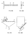
- FIG. 10A is a side view that shows a conventional film peeling device
- FIG. 10B is a front view of this film peeling device
- FIG. 10C shows a film peeling method using a conventional film peeling device, viewed from the side of a bulb (envelope)
- FIG. 10D shows this film peeling method, viewed from the front side of the bulb.
- a conventional film peeling device is configured from an approximately cylindrical main body portion 15 consisting of SUS (stainless steel) or iron pipe with a diameter of about 20 mm to 25 mm, and a handle portion 16 for rotating the main body portion 15.
- a slit 15a is formed with a width of approximately 0.5 mm in order to grasp an end of a film 11 (see FIGS. 10C and 10D) in the lengthwise direction of the main body portion 15.
- the workload necessary for peeling off a film in a 32 inch cathode ray tube after 10 years is 5 N ⁇ m or more, and this is not a situation in which peeling can be performed by a worker using a manually operated device as described above.
- the present invention was made in order to solve the problems in the conventional technology described above, and it is an object thereof to provide a film peeling method and a film peeling device with which it is possible to easily peel off a film that has been firmly stuck on the display panel.
- a film peeling method for display panel includes peeling off an end of a film that has been stuck on a display panel, fixing the peeled end of the film to a roller that is adjacent to or in contact with a panel face of the display panel, and peeling off the film from the display panel by rotationally driving the roller.
- the peeled end of the film is fixed to the roller.
- a configuration of a film peeling device for display panel according to the present invention is provided with a rotationally drivable roller that has an effective length that is longer than the short side of a display panel, a contact plate disposed such that it fits closely with the surface of the roller, and a mechanism that presses the contact plate against the surface of the roller.
- the mechanism that presses the contact plate against the surface of the roller constitutes a pair of toggle clamps provided outside of the effective length of the roller.
- the roller is a motor roller that has a self-rotating function.
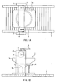
- FIG. 1A is a plan view that shows a film peeling device according to one embodiment of the present invention
- FIG. 1B is a side view that shows the film peeling device.
- the inventors of the present invention invented a film peeling method and a film peeling device with which it is possible to peel off, easily and reliably, film that has been firmly stuck on the display panel.
- FIG. 1A is a plan view that shows a film peeling device according to one embodiment of the present invention
- FIG. 1B is a side view that shows the film peeling device.
- the film peeling device is configured from a transport system 1 in which a bulb 7 of a cathode ray tube is transportable, a cylindrical motor roller 3 that has a rotation function disposed above the transport system 1, a contact plate 4 with an arc-shaped cross-section that has a curvature about the same as the curvature of the outer circumferential face of the motor roller 3, and a pair of toggle clamps 5 for pressing the contact plate 4 against the outer circumferential face of the motor roller 3, disposed near both ends of the contact plate 4.
- the motor roller 3 and the contact plate 4 have an effective length that is longer than the short side of a face panel 7a.
- a film 11 that is held sandwiched between the motor roller 3 and the contact plate 4 is peeled off while being rolled up in the motor roller 3, so that the pair of toggle clamps 5 are provided outside of the effective length of the motor roller 3.
- the motor roller 3 is supported in a horizontal state perpendicular to the transport direction of the bulb 7 by portal support pillars 2 provided at both sides of the transport system 1.
- the contact plate 4 has a structure in which one side of the contact plate 4 is fixed to the motor roller 3 using a hinge, and only the opposite side can be opened and closed (see FIG. 3).
- the bulb 7 is mounted to the transport pallet 6 in a state with the face panel 7a on top, and transported on the transport system 1.
- the motor roller 3 is adjacent to or in contact with the panel face of the face panel 7a.
- FIG. 2 shows the configuration of the transport pallet (FIG. 2A is a plan view, and FIG. 2B is a side view).
- a transport pallet 6 has a simple structure in which a pipe (a round pipe) 6a formed bent in a round shape is merely fixed to a frame 6b in a horizontal state.
- the round pipe 6a of the transport pallet 6, by making contact with an inclined face of a funnel 7b of the bulb 7, can hold any size of bulb 7 in a state with the face panel 7a on top. Because the bulb 7 has a great deal of weight, even if a no special means for fixing the bulb 7 to the transport pallet 6 is provided, it is possible to fix the bulb 7 to some extent.
- FIG. 3A is a side view that shows a state prior to grasping of a film grasping mechanism of a film peeling device according to one embodiment of the present invention
- FIG. 3B is a side view that shows a state when the film grasping mechanism is grasping.
- the side (the left side in FIG. 3A) of the contact plate 4 that is not fixed with the hinge is in a state in which it can easily be opened and closed.
- the end of the film 11 that has been peeled off is inserted between the motor roller 3 and the contact plate 4 by a worker.
- FIG. 3B by fastening the toggle clamps 5, the contact plate 4 is pressed against the outer circumferential face of the motor roller 3, and the end of the film 11 is grasped by the contact plate 4 and the outer circumferential face of the motor roller 3.
- a television receiver that a consumer has finished using is brought into a reprocessing plant, and the bulb 7 is removed manually.
- the bulb 7 is mounted to the transport pallet 6 on the transport system 1 in a state with the face panel 7a on top, and transported to the position of the motor roller 3 (the state in FIGS. 1A and 1B).
- several centimeters of the film 11 are peeled from the short side of the face panel 7a by a worker, and the peeled end of the film 11 is inserted between the motor roller 3 and the contact plate 4 by the worker (the state in FIG. 3A).
- the toggle clamps 5 are fastened by the worker.
- the contact plate 4 is pressed against the outer circumferential face of the motor roller 3, and the end of the film 11 is grasped by the contact plate 4 and the outer circumferential face of the motor roller 3 (the state in FIG. 3B).
- the end of the film 11 can be peeled effectively if an electrical tool that has a chisel-like blade edge and can move back and forth in the direction perpendicular to the blade edge is used.
- the bulb 7 After being converted to only glass material, the bulb 7 is divided into the face panel 7a, which does not include lead, and the funnel 7b, which contains lead, and the face panel 7a and the funnel 7b respectively can be regenerated as the bulb of a television receiver again.
- the film peeling device of the present embodiment If the film peeling device of the present embodiment is used, the film 11 that has been firmly stuck on the face panel 7a can be peeled by anyone easily and reliably. As a result, it is possible to achieve an improvement in the recycling efficiency of the bulb 7 of a cathode ray tube whose role in the marketplace is finished. Also, because it is thus possible to establish, with energy conservation, an earth-friendly recycling method, such as a recycling method that conserves the global environment and effectively uses resources, the present invention has a high industrial value, and also a high value from the viewpoint of the global environment.
- the toggle clamps 5 were used to press the contact plate 4 against the outer circumferential face of the motor roller 3, but the present invention is not necessarily limited to that configuration.
- a configuration may also be adopted in which the contact plate 4 is pressed against the outer circumferential face of the motor roller 3 using a cylinder apparatus.
- a combination of the cylindrical motor roller 3 and the contact plate 4 with an arc-shaped cross-section having a curvature about the same as the curvature of the outer circumferential face of the motor roller 3 was described by way of example, but the present invention is not necessarily limited to a combination of the motor roller 3 and the contact plate 4 with that form. For example, as shown in FIG.
- a configuration may also be adopted in which a cylindrical motor roller 3 in which a concave groove 3a is formed in the lengthwise direction, and a contact plate 4 with an arc-shaped cross-section having a curvature about the same as the curvature of the outer circumferential face of the motor roller 3, in which a convexity 4a that can be inserted into the concave groove 3a is formed in the lengthwise direction, are combined.
- a convexity 4a that can be inserted into the concave groove 3a is formed in the lengthwise direction
- FIG. 6 As a combination of the motor roller 3 and the contact plate 4 that produces the above sort of effect, other various modes are conceivable. This is shown in FIG. 6.
- a convexity 3b is formed in the lengthwise direction in the cylindrical motor roller 3, and a groove portion constituted from a pair of convexities 4b into which the convexity 3b can be inserted is formed in the lengthwise direction in the contact plate 4 with an arc-shaped cross-section.
- a flat portion 3c is formed in the lengthwise direction in the cylindrical motor roller 3
- the contact plate 4 is formed in a flat shape corresponding to the flat portion 3c.
- the concave groove 3a is formed in the lengthwise direction in the flat portion 3c, and along with the contact plate 4 being formed in a flat shape corresponding to the flat portion 3c, a convexity 4b that can be inserted into the concave groove 3a is formed in the lengthwise direction in the contact plate 4.
- the convexity 3b is formed in the lengthwise direction in the flat portion 3c, and along with the contact plate 4 being formed in a flat shape corresponding to the flat portion 3c, a groove portion constituted from a pair of convexities 4b into which the convexity 3b can be inserted is formed in the lengthwise direction in the contact plate 4.
- the contact plate 4 is pressed against the outer circumferential face of the motor roller 3 from above (see FIGS. 3A and 3B), but as shown in FIG. 7, a configuration may also be adopted in which a film grasping mechanism constituted from the motor roller 3, the contact plate 4, and the toggle clamps 5 is disposed rotated to the left 160° from the state in FIG. 3, and the contact plate 4 is pressed against the outer circumferential face of the motor roller 3 from below.
- a configuration using a motor roller 3 having a self-rotating function was described by way of example, but the present invention is not necessarily limited to this configuration.
- a configuration may also be adopted that uses simply a roller 8 instead of the motor roller 3.
- the roller 8 is joined to a drive motor 9 via a transmission belt 12.
- a switch for the drive motor 9 By turning on a switch for the drive motor 9, it is possible to rotationally drive the roller 8.
- the modifications as shown in FIGS. 4 to 6 can be added to the roller 8 and the contact plate 4.
- a configuration is adopted in which, in a state with the face panel 7a and the funnel 7b being a single body in the bulb 7, the film 11 that has been stuck on the face panel 7a is peeled, but a configuration may also be adopted in which, as shown in FIGS. 9A and 9B, in a state with only the face panel 7a, the film 11 that has been stuck on the face panel 7a is peeled.
- the face panel 7a is ordinarily severed using an electrically heated wire and separated from the bulb 7.
- the shape of the severed face is often irregular, and so by placing the face panel 7a on the flat transport pallet, the face on which the film 11 has been stuck slants, and so it is not possible to smoothly perform work to peel off the film 11.
- four support pins 14 are planted near the four corners of the flat transport pallet 13, and by the four support pins 14, the face panel 7a is supported in a state with its surface facing upward.
- the number of support pins 14 is not limited to four, and may be any number of pins as long as it is possible to keep a horizontal state for the face of the face panel 7a on which the film 11 has been stuck.
- the face panel 7a constituting the bulb 7 of a cathode ray tube was described by way of example, but the present invention is not limited to a method and device that peel off the film 11 that has been stuck on the face panel 7a.
- the present invention when peeling off a deflecting film or protective film that has been stuck on the front and rear faces of a PDP or LCD panel.
- the film peeling method and film peeling device of the above embodiment also can be applied when peeling off, other than film of a display panel, for example, color film or the like that has been stuck on automobile glass.
- film peeling method and the film peeling device of the present invention for example, film that has been firmly stuck on a display panel with the passage of ten years can be easily peeled, it is possible to improve the recycle rate of television receivers, and by extension to make a contribution to the effective application of earth resources, so the industrial utility value of the present invention is extremely high.
Landscapes
- Engineering & Computer Science (AREA)
- Manufacturing & Machinery (AREA)
- Manufacture Of Electron Tubes, Discharge Lamp Vessels, Lead-In Wires, And The Like (AREA)
- Liquid Crystal (AREA)
- Processing Of Solid Wastes (AREA)
- Separation, Recovery Or Treatment Of Waste Materials Containing Plastics (AREA)
- Devices For Indicating Variable Information By Combining Individual Elements (AREA)
Abstract

Description
- The present invention relates to a film peeling method and a film peeling device for peeling off a film stuck on a display panel of a display device such as a cathode ray tube (CRT), a liquid crystal display (LCD), or a plasma display panel (PDP).
- In recent years, due to the growth of electronics technology and an increase in user needs, efforts to increase the size and image quality of television receivers have been advancing. In cathode ray tubes that deal with increased size and image quality of television receivers, in order to obtain a high quality color image, a resin film sometimes is stuck on the surface of a face panel (display panel). This resin film has various purposes, such as preventing the reflection of external light, and preventing the face panel from becoming electrically charged by high voltage (about 40kV) generated when the television receiver is switched on.
- As one example of resin film, an AR (anti-reflection: low reflection) film for preventing reflection of external light or a conducting film for preventing charging are coated on a PET (polyethylene terephthalate) film with a thickness of 100 µm to 250 µm, and an adhesive with a thickness of 20 µm to 50 µm is added. The adhesive used in this resin film is 99% acrylic polymer, and the remaining 1% is a solvent for adhesion. This resin film is stuck on the surface of the face panel of a cathode ray tube using a special applicator provided with a rubber roller.
- A television receiver on which resin film has been stuck as described above, after its role in the marketplace is finished, is brought into a reprocessing plant, and is processed to be recycled. With respect to the face panel of the cathode ray tube, a path in which after attachment such as fluorescent material has been removed, it is crushed, and it can be recycled as a cathode ray tube again is already completed. Also, with respect to the resin film, in order to perform recycling it is necessary to delaminate the adhesive.
- Conventionally, as a film peeling device for peeling off a film stuck on a display panel, film peeling devices with the below sort of configuration are known (for example, see
JP H11-149871A - FIG. 10A is a side view that shows a conventional film peeling device, and FIG. 10B is a front view of this film peeling device. FIG. 10C shows a film peeling method using a conventional film peeling device, viewed from the side of a bulb (envelope), and FIG. 10D shows this film peeling method, viewed from the front side of the bulb.
- As shown in FIGS. 10A and 10B, a conventional film peeling device is configured from an approximately cylindrical
main body portion 15 consisting of SUS (stainless steel) or iron pipe with a diameter of about 20 mm to 25 mm, and ahandle portion 16 for rotating themain body portion 15. In themain body portion 15, aslit 15a is formed with a width of approximately 0.5 mm in order to grasp an end of a film 11 (see FIGS. 10C and 10D) in the lengthwise direction of themain body portion 15. When using this film peeling device, the film that has been stuck on the surface of the face panel of the cathode ray tube is peeled in the manner below. That is, as shown in FIGS. 10C and 10D, first, in theslit 15a that has been formed in themain body portion 15 of the film peeling device, 1 cm or more of the end of thefilm 11 stuck on the surface of aface panel 7a that constitutes a bulb 7 of the cathode ray tube is inserted, forming a "tongue". Next, by grasping ahandle portion 16 and rotating themain body portion 15, thefilm 11 is rolled up in themain body portion 15. - However, with respect to PET film that has been stuck on the surface of the face panel of a cathode ray tube that has been recovered from the marketplace it is presumed that a cross-linking reaction of the adhesive will advance due to the passage of several years' time or more. According to the results of accelerated test performed by the inventors of the present invention, the workload necessary for peeling off a film in a 32 inch cathode ray tube after 10 years is 5 N·m or more, and this is not a situation in which peeling can be performed by a worker using a manually operated device as described above.
- The present invention was made in order to solve the problems in the conventional technology described above, and it is an object thereof to provide a film peeling method and a film peeling device with which it is possible to easily peel off a film that has been firmly stuck on the display panel.
- To achieve the above object, a film peeling method for display panel according to the present invention includes peeling off an end of a film that has been stuck on a display panel, fixing the peeled end of the film to a roller that is adjacent to or in contact with a panel face of the display panel, and peeling off the film from the display panel by rotationally driving the roller.
- Also, in the film peeling method of the present invention, it is preferable that by inserting the peeled end of the film between the surface of the roller and a contact plate disposed such that it fits closely with the surface of the roller, and pressing the contact plate against the surface of the roller, the peeled end of the film is fixed to the roller.
- Also, a configuration of a film peeling device for display panel according to the present invention is provided with a rotationally drivable roller that has an effective length that is longer than the short side of a display panel, a contact plate disposed such that it fits closely with the surface of the roller, and a mechanism that presses the contact plate against the surface of the roller.
- Also, in the configuration of the film peeling device of the present invention, it is preferable that the mechanism that presses the contact plate against the surface of the roller constitutes a pair of toggle clamps provided outside of the effective length of the roller.
- Also, in the configuration of the film peeling device of the present invention, it is preferable that the roller is a motor roller that has a self-rotating function.
- According to the present invention, it is possible for anyone to easily peel off a film that has been firmly stuck on the display panel reliably.
- [FIG. 1] FIG. 1A is a plan view that shows a film peeling device according to one embodiment of the present invention, and FIG. 1B is a side view that shows the film peeling device.
- [FIG. 2] FIG. 2A is a plan view that shows a transport pallet of a film peeling device according to one embodiment of the present invention, and FIG. 2B is a side view that shows the transport pallet.
- [FIG. 3] FIG. 3A is a side view that shows a state prior to grasping of a film grasping mechanism of a film peeling device according to one embodiment of the present invention, and FIG. 3B is a side view that shows a state when the film grasping mechanism is grasping.
- [FIG. 4] FIG. 4 is a perspective view that shows another example of a motor roller and contact plate of a film peeling device according to one embodiment of the present invention.
- [FIG. 5] FIG. 5 is a perspective view that shows still another example of a motor roller and contact plate of a film peeling device according to one embodiment of the present invention.
- [FIG. 6] FIGS. 6A to 6D are side views that show examples of various combinations of a motor roller and contact plate of a film peeling device according to one embodiment of the present invention.
- [FIG. 7] FIG. 7A is a side view that shows a state prior to grasping of another example of a film grasping mechanism of a film peeling device according to one embodiment of the present invention, and FIG. 7B is a side view that shows a state when the film grasping mechanism is grasping.
- [FIG. 8] FIG. 8 is a side view that shows another example of a film peeling device according to one embodiment of the present invention.
- [FIG. 9] FIG. 9A is a side view that shows a transport pallet and face panel when peeling off a film in a state with only a face panel according to one embodiment of the present invention, and FIG. 9B is a plan view that shows the transport pallet and face panel.
- [FIG. 10] FIG. 10A is a side view that shows a conventional film peeling device, FIG. 10B is a front view that shows the film peeling device, FIG. 10C shows a film peeling method using a conventional film peeling device, viewed from the side face side of a bulb, and FIG. 10D shows the film peeling method, viewed from the front face side of the bulb.
- In order to reuse the glass resources of a display panel whose role in the marketplace is finished and has been recovered, it is necessary to peel off a film that has been stuck on the display panel. The inventors of the present invention invented a film peeling method and a film peeling device with which it is possible to peel off, easily and reliably, film that has been firmly stuck on the display panel.
- Below, the present invention will be described more specifically using embodiments.
- First is a description of a film peeling device according to the present invention with reference to FIG. 1. FIG. 1A is a plan view that shows a film peeling device according to one embodiment of the present invention, and FIG. 1B is a side view that shows the film peeling device.
- As shown in FIGS. 1A and 1B, the film peeling device according to this embodiment is configured from a
transport system 1 in which a bulb 7 of a cathode ray tube is transportable, acylindrical motor roller 3 that has a rotation function disposed above thetransport system 1, acontact plate 4 with an arc-shaped cross-section that has a curvature about the same as the curvature of the outer circumferential face of themotor roller 3, and a pair of toggle clamps 5 for pressing thecontact plate 4 against the outer circumferential face of themotor roller 3, disposed near both ends of thecontact plate 4. Here, themotor roller 3 and thecontact plate 4 have an effective length that is longer than the short side of aface panel 7a. Also, as described below, afilm 11 that is held sandwiched between themotor roller 3 and thecontact plate 4 is peeled off while being rolled up in themotor roller 3, so that the pair of toggle clamps 5 are provided outside of the effective length of themotor roller 3. - The
motor roller 3 is supported in a horizontal state perpendicular to the transport direction of the bulb 7 byportal support pillars 2 provided at both sides of thetransport system 1. Thecontact plate 4 has a structure in which one side of thecontact plate 4 is fixed to themotor roller 3 using a hinge, and only the opposite side can be opened and closed (see FIG. 3). - The bulb 7 is mounted to the
transport pallet 6 in a state with theface panel 7a on top, and transported on thetransport system 1. When the bulb 7 has been transported to the position of themotor roller 3, themotor roller 3 is adjacent to or in contact with the panel face of theface panel 7a. - FIG. 2 shows the configuration of the transport pallet (FIG. 2A is a plan view, and FIG. 2B is a side view). As shown in FIG. 2, a
transport pallet 6 has a simple structure in which a pipe (a round pipe) 6a formed bent in a round shape is merely fixed to aframe 6b in a horizontal state. Theround pipe 6a of thetransport pallet 6, by making contact with an inclined face of afunnel 7b of the bulb 7, can hold any size of bulb 7 in a state with theface panel 7a on top. Because the bulb 7 has a great deal of weight, even if a no special means for fixing the bulb 7 to thetransport pallet 6 is provided, it is possible to fix the bulb 7 to some extent. - Next is a description of a film end grasping method with reference to FIG. 3. FIG. 3A is a side view that shows a state prior to grasping of a film grasping mechanism of a film peeling device according to one embodiment of the present invention, and FIG. 3B is a side view that shows a state when the film grasping mechanism is grasping. In the state prior to grasping in FIG. 3A, because the toggle clamps 5 are in an opened state, the side (the left side in FIG. 3A) of the
contact plate 4 that is not fixed with the hinge is in a state in which it can easily be opened and closed. The end of thefilm 11 that has been peeled off is inserted between themotor roller 3 and thecontact plate 4 by a worker. Afterward, as shown in FIG. 3B, by fastening the toggle clamps 5, thecontact plate 4 is pressed against the outer circumferential face of themotor roller 3, and the end of thefilm 11 is grasped by thecontact plate 4 and the outer circumferential face of themotor roller 3. - Next is a description of the film peeling method in the present embodiment with reference to FIGS. 1 to 3.
- A television receiver that a consumer has finished using is brought into a reprocessing plant, and the bulb 7 is removed manually. The bulb 7 is mounted to the
transport pallet 6 on thetransport system 1 in a state with theface panel 7a on top, and transported to the position of the motor roller 3 (the state in FIGS. 1A and 1B). Then, several centimeters of thefilm 11 are peeled from the short side of theface panel 7a by a worker, and the peeled end of thefilm 11 is inserted between themotor roller 3 and thecontact plate 4 by the worker (the state in FIG. 3A). Next, the toggle clamps 5 are fastened by the worker. Thus, thecontact plate 4 is pressed against the outer circumferential face of themotor roller 3, and the end of thefilm 11 is grasped by thecontact plate 4 and the outer circumferential face of the motor roller 3 (the state in FIG. 3B). When peeling off the end of thefilm 11, the end of thefilm 11 can be peeled effectively if an electrical tool that has a chisel-like blade edge and can move back and forth in the direction perpendicular to the blade edge is used. - When the end of the
film 11 is grasped by thecontact plate 4 and the outer circumferential face of themotor roller 3 as described above, a switch for themotor roller 3 is turned on, rotationally driving the motor roller 3 (see the arrow → in FIG. 3B). Thus, while the bulb 7 (theface panel 7a in FIG. 3B) moves on thetransport system 1 in the direction of the arrow ⇒ in FIG. 3B, thefilm 11 is rolled up in themotor roller 3, and peeled from theface panel 7a. - After being converted to only glass material, the bulb 7 is divided into the
face panel 7a, which does not include lead, and thefunnel 7b, which contains lead, and theface panel 7a and thefunnel 7b respectively can be regenerated as the bulb of a television receiver again. - If the film peeling device of the present embodiment is used, the
film 11 that has been firmly stuck on theface panel 7a can be peeled by anyone easily and reliably. As a result, it is possible to achieve an improvement in the recycling efficiency of the bulb 7 of a cathode ray tube whose role in the marketplace is finished. Also, because it is thus possible to establish, with energy conservation, an earth-friendly recycling method, such as a recycling method that conserves the global environment and effectively uses resources, the present invention has a high industrial value, and also a high value from the viewpoint of the global environment. - In the embodiment described above, the toggle clamps 5 were used to press the
contact plate 4 against the outer circumferential face of themotor roller 3, but the present invention is not necessarily limited to that configuration. For example, a configuration may also be adopted in which thecontact plate 4 is pressed against the outer circumferential face of themotor roller 3 using a cylinder apparatus. - Also, in the embodiment above, a combination of the
cylindrical motor roller 3 and thecontact plate 4 with an arc-shaped cross-section having a curvature about the same as the curvature of the outer circumferential face of themotor roller 3 was described by way of example, but the present invention is not necessarily limited to a combination of themotor roller 3 and thecontact plate 4 with that form. For example, as shown in FIG. 4, a configuration may also be adopted in which acylindrical motor roller 3 in which aconcave groove 3a is formed in the lengthwise direction, and acontact plate 4 with an arc-shaped cross-section having a curvature about the same as the curvature of the outer circumferential face of themotor roller 3, in which aconvexity 4a that can be inserted into theconcave groove 3a is formed in the lengthwise direction, are combined. With this combination, it is possible to grasp the end of thefilm 11 firmly, and so it is possible to peel off thefilm 11 from theface panel 7a reliably. Also, as shown in FIG. 5, theconcave groove 3a and theconvexity 4a may be divided into a plurality of sections. - As a combination of the
motor roller 3 and thecontact plate 4 that produces the above sort of effect, other various modes are conceivable. This is shown in FIG. 6. In the combination shown in FIG. 6A, aconvexity 3b is formed in the lengthwise direction in thecylindrical motor roller 3, and a groove portion constituted from a pair ofconvexities 4b into which theconvexity 3b can be inserted is formed in the lengthwise direction in thecontact plate 4 with an arc-shaped cross-section. In the combination shown in FIG. 6B, aflat portion 3c is formed in the lengthwise direction in thecylindrical motor roller 3, and thecontact plate 4 is formed in a flat shape corresponding to theflat portion 3c. In the combination shown in FIG. 6C, along with theflat portion 3c being formed in the lengthwise direction in thecylindrical motor roller 3, theconcave groove 3a is formed in the lengthwise direction in theflat portion 3c, and along with thecontact plate 4 being formed in a flat shape corresponding to theflat portion 3c, aconvexity 4b that can be inserted into theconcave groove 3a is formed in the lengthwise direction in thecontact plate 4. In the combination shown in FIG. 6D, along with theflat portion 3c being formed in the lengthwise direction in thecylindrical motor roller 3, theconvexity 3b is formed in the lengthwise direction in theflat portion 3c, and along with thecontact plate 4 being formed in a flat shape corresponding to theflat portion 3c, a groove portion constituted from a pair ofconvexities 4b into which theconvexity 3b can be inserted is formed in the lengthwise direction in thecontact plate 4. - Also, in the above embodiment, the
contact plate 4 is pressed against the outer circumferential face of themotor roller 3 from above (see FIGS. 3A and 3B), but as shown in FIG. 7, a configuration may also be adopted in which a film grasping mechanism constituted from themotor roller 3, thecontact plate 4, and the toggle clamps 5 is disposed rotated to the left 160° from the state in FIG. 3, and thecontact plate 4 is pressed against the outer circumferential face of themotor roller 3 from below. If a configuration is adopted in which thecontact plate 4 is pressed against the outer circumferential face of themotor roller 3 from below, it is possible to bring the pressed face and the end of thefilm 11 close together, and so it is possible to reduce the amount of the end of thefilm 11 that is peeled manually by the worker. As a result, it is possible to reduce the burden on the worker, and thefilm 11 that has been stuck on theface panel 7a can be peeled more easily. - Also, in the embodiment above, a configuration using a
motor roller 3 having a self-rotating function was described by way of example, but the present invention is not necessarily limited to this configuration. As shown in FIG. 8, a configuration may also be adopted that uses simply aroller 8 instead of themotor roller 3. In this case, theroller 8 is joined to adrive motor 9 via atransmission belt 12. By turning on a switch for thedrive motor 9, it is possible to rotationally drive theroller 8. In this case as well, the modifications as shown in FIGS. 4 to 6 can be added to theroller 8 and thecontact plate 4. - Also, in the embodiment above, a configuration is adopted in which, in a state with the
face panel 7a and thefunnel 7b being a single body in the bulb 7, thefilm 11 that has been stuck on theface panel 7a is peeled, but a configuration may also be adopted in which, as shown in FIGS. 9A and 9B, in a state with only theface panel 7a, thefilm 11 that has been stuck on theface panel 7a is peeled. Theface panel 7a is ordinarily severed using an electrically heated wire and separated from the bulb 7. In this case, the shape of the severed face is often irregular, and so by placing theface panel 7a on the flat transport pallet, the face on which thefilm 11 has been stuck slants, and so it is not possible to smoothly perform work to peel off thefilm 11. Accordingly, in this case, four support pins 14 are planted near the four corners of theflat transport pallet 13, and by the four support pins 14, theface panel 7a is supported in a state with its surface facing upward. Thus, regardless of the shape of the severed face of theface panel 7a, it is possible to keep a horizontal state for the face on which thefilm 11 has been stuck. The number of support pins 14 is not limited to four, and may be any number of pins as long as it is possible to keep a horizontal state for the face of theface panel 7a on which thefilm 11 has been stuck. - Also, in the embodiment above, as a display panel, the
face panel 7a constituting the bulb 7 of a cathode ray tube was described by way of example, but the present invention is not limited to a method and device that peel off thefilm 11 that has been stuck on theface panel 7a. For example, it is also possible to apply the present invention when peeling off a deflecting film or protective film that has been stuck on the front and rear faces of a PDP or LCD panel. The film peeling method and film peeling device of the above embodiment also can be applied when peeling off, other than film of a display panel, for example, color film or the like that has been stuck on automobile glass. - According to the film peeling method and the film peeling device of the present invention, for example, film that has been firmly stuck on a display panel with the passage of ten years can be easily peeled, it is possible to improve the recycle rate of television receivers, and by extension to make a contribution to the effective application of earth resources, so the industrial utility value of the present invention is extremely high.
Claims (5)
- A film peeling method for a display panel, comprising:peeling off an end of a film that has been stuck on a display panel;fixing the peeled end of the film to a roller that is adjacent to or in contact with a panel face of the display panel, andpeeling off the film from the display panel by rotationally driving the roller.
- The film peeling method according to claim 1, wherein by inserting the peeled end of the film between the surface of the roller and a contact plate disposed such that it fits closely with the surface of the roller, and pressing the contact plate against the surface of the roller, the delaminated edge of the film is fixed to the roller.
- A film peeling device for a display panel, comprising:a rotationally drivable roller that has an effective length that is longer than the short side of a display panel,a contact plate disposed such that it fits closely with the surface of the roller, anda mechanism that presses the contact plate against the surface of the roller.
- The film peeling device according to claim 3, wherein the mechanism that presses the contact plate against the surface of the roller is comprised of a pair of toggle clamps provided outside of the effective length of the roller.
- The film peeling device according to claim 3, wherein the roller is a motor roller that has a self-rotating function.
Applications Claiming Priority (2)
| Application Number | Priority Date | Filing Date | Title |
|---|---|---|---|
| JP2004012637 | 2004-01-21 | ||
| PCT/JP2005/000542 WO2005070573A1 (en) | 2004-01-21 | 2005-01-18 | Film peeling method and film peeling device for display panel |
Publications (3)
| Publication Number | Publication Date |
|---|---|
| EP1707279A1 true EP1707279A1 (en) | 2006-10-04 |
| EP1707279A4 EP1707279A4 (en) | 2010-05-05 |
| EP1707279B1 EP1707279B1 (en) | 2013-03-06 |
Family
ID=34805352
Family Applications (1)
| Application Number | Title | Priority Date | Filing Date |
|---|---|---|---|
| EP05703779A Ceased EP1707279B1 (en) | 2004-01-21 | 2005-01-18 | Film peeling method for display panel |
Country Status (5)
| Country | Link |
|---|---|
| US (1) | US8142610B2 (en) |
| EP (1) | EP1707279B1 (en) |
| JP (1) | JPWO2005070573A1 (en) |
| CN (1) | CN1909982B (en) |
| WO (1) | WO2005070573A1 (en) |
Cited By (2)
| Publication number | Priority date | Publication date | Assignee | Title |
|---|---|---|---|---|
| CN103522728A (en) * | 2013-07-31 | 2014-01-22 | 深圳市永能机械有限公司 | Automatic adhesive tearing-off equipment and method |
| CN105552169A (en) * | 2016-01-27 | 2016-05-04 | 苏州丰积能源科技有限公司 | Photovoltaic module repair device and repair technology |
Families Citing this family (31)
| Publication number | Priority date | Publication date | Assignee | Title |
|---|---|---|---|---|
| JP4445457B2 (en) * | 2005-11-11 | 2010-04-07 | 株式会社アドテックエンジニアリング | Film peeling device |
| KR20080089730A (en) * | 2007-04-02 | 2008-10-08 | 삼성전자주식회사 | Apparatus and method for removing polarizer |
| CN101531086B (en) * | 2008-03-12 | 2013-08-28 | 鸿富锦精密工业(深圳)有限公司 | Film peeling mechanism and film peeling device using same |
| US20090229766A1 (en) * | 2008-03-14 | 2009-09-17 | Aveldson Jason L | Adhesive removal device |
| KR101818473B1 (en) * | 2011-11-30 | 2018-01-16 | 엘지디스플레이 주식회사 | Apparatus and Method for peeling protection film |
| TW201343526A (en) * | 2012-04-24 | 2013-11-01 | Hon Hai Prec Ind Co Ltd | Feeder |
| US8469076B1 (en) * | 2012-05-10 | 2013-06-25 | Shenzhen China Star Optoelectronics Technology Co., Ltd. | Polarizer film peeling machine and polarizer film peeling method thereof |
| KR102006876B1 (en) * | 2012-09-04 | 2019-08-05 | 삼성디스플레이 주식회사 | Film peeling apparatus and film peeling method using the same |
| KR101980764B1 (en) | 2012-12-24 | 2019-08-28 | 엘지디스플레이 주식회사 | Desorption apparatus having drum pad of arch form and method of fabricating lightweight and thin liquid crystal display device using thereof |
| JP5585669B2 (en) * | 2013-01-16 | 2014-09-10 | 三菱マテリアル株式会社 | Fixing member dismantling system, fixing member disassembling method, and program |
| CN103456689B (en) * | 2013-08-13 | 2015-02-25 | 京东方科技集团股份有限公司 | Device for separating flexible substrate from glass substrate and production device |
| CN103448347B (en) * | 2013-08-19 | 2015-08-26 | 无锡市兰翔胶业有限公司 | The automatic stripping machine of a kind of cushion rubber |
| JP6258736B2 (en) * | 2013-09-13 | 2018-01-10 | 日東電工株式会社 | Peeling member, peeling device and peeling method |
| US9254636B2 (en) | 2013-09-24 | 2016-02-09 | Apple Inc. | Display module reworkability |
| KR102159738B1 (en) * | 2013-11-01 | 2020-09-24 | 삼성디스플레이 주식회사 | Flexible device peeling apparatus and peeling method using the same |
| CN103753944B (en) * | 2014-01-15 | 2015-10-14 | 京东方科技集团股份有限公司 | A kind of method and apparatus that flexible display film is peeled off |
| KR20150117769A (en) * | 2014-04-10 | 2015-10-21 | 삼성디스플레이 주식회사 | Manufacturing method of device substrate |
| CN103950269B (en) * | 2014-04-23 | 2016-03-30 | 京东方科技集团股份有限公司 | Polarizer stripping device |
| KR101701566B1 (en) * | 2014-08-14 | 2017-02-01 | 주식회사 엘지화학 | Bar for peeling off polarizing film from panel, apparatus and method using the same |
| US9751293B2 (en) * | 2014-12-04 | 2017-09-05 | Industrial Technology Research Institute | Laminated substrate separating device and method for separating laminated substrate |
| CN105118897B (en) * | 2015-09-18 | 2017-08-11 | 英利能源(中国)有限公司 | Stripping machine and the stripping system for photovoltaic component back plate |
| US9970205B2 (en) * | 2016-04-15 | 2018-05-15 | Roberto Mora | Carpet removal tool |
| CN206781204U (en) * | 2017-06-09 | 2017-12-22 | 合肥鑫晟光电科技有限公司 | A kind of coat peeling unit |
| KR102424743B1 (en) * | 2017-10-13 | 2022-07-26 | 삼성디스플레이 주식회사 | Protecting film peeling device and peeling method for the same |
| CN109334215B (en) * | 2018-11-28 | 2023-05-16 | 深圳市诺峰光电设备有限公司 | Automatic dyestripping machine of auxiliary material equipment |
| US11492222B2 (en) | 2020-02-19 | 2022-11-08 | Ricoh Company, Ltd. | Sheet separation device, laminator, image forming apparatus, and image forming system |
| CN112871880B (en) * | 2020-12-23 | 2022-03-04 | 浙江雷拉激光科技有限公司 | Automatic cleaning method for ray tube |
| WO2023095627A1 (en) * | 2021-11-24 | 2023-06-01 | ソーラーフロンティア株式会社 | Dismantling method and dismantling device |
| CN115384888B (en) * | 2022-08-24 | 2024-06-18 | 京东方科技集团股份有限公司 | Film peeling equipment and film peeling method |
| US11883933B1 (en) | 2022-08-24 | 2024-01-30 | Ifixit | Screw-driven spreading tool with a disengage |
| TWI847666B (en) * | 2023-04-25 | 2024-07-01 | 昌陽科技有限公司 | Film recycling device |
Family Cites Families (17)
| Publication number | Priority date | Publication date | Assignee | Title |
|---|---|---|---|---|
| US1186729A (en) * | 1915-02-24 | 1916-06-13 | Benjamin E Baker | Rug-extractor. |
| US3830441A (en) * | 1972-02-08 | 1974-08-20 | Quiston H Mc | Method of installation of thermal building insulation and stretchers therefor |
| US4373611A (en) * | 1980-10-01 | 1983-02-15 | Frederick Roderick J | Conveyor to interfit with a loaded shopping cart and to move portions of the load, on demand of a checker, to the front of the cart, for removal, price scanning, and bagging, by the checker at a checkout stand |
| DE3700615A1 (en) * | 1987-01-10 | 1988-07-21 | Schmid Gmbh & Co Geb | METHOD AND DEVICE FOR REMOVING A PROTECTIVE FILM |
| JPH02250057A (en) * | 1989-03-24 | 1990-10-05 | Emunikoo:Kk | Protective film stripping machine |
| CN2052140U (en) | 1989-05-05 | 1990-01-31 | 株式会社Skc(此公司为公知) | Video tape reels |
| US5466325A (en) * | 1993-06-02 | 1995-11-14 | Nitto Denko Corporation | Resist removing method, and curable pressure-sensitive adhesive, adhesive sheets and apparatus used for the method |
| JPH07215577A (en) * | 1994-01-31 | 1995-08-15 | Canon Inc | How to peel off parts |
| JPH09197394A (en) * | 1996-01-23 | 1997-07-31 | Hitachi Ltd | Polarizer peeling device |
| US5891297A (en) * | 1997-10-29 | 1999-04-06 | Sharp Microelectronics Technology, Inc. | System and method for peeling a polarized film |
| JPH11149871A (en) | 1997-11-17 | 1999-06-02 | Sony Corp | Film peeling apparatus and method |
| KR100543024B1 (en) * | 1998-01-21 | 2006-05-25 | 삼성전자주식회사 | Polarizer Removal Device of Liquid Crystal Display |
| DE19808931B4 (en) * | 1998-03-03 | 2005-11-24 | Volker Lins | Apparatus for removing a sheet-like film adhering to a surface or the like. |
| JP3619058B2 (en) * | 1998-06-18 | 2005-02-09 | キヤノン株式会社 | Manufacturing method of semiconductor thin film |
| US6199616B1 (en) * | 1998-11-23 | 2001-03-13 | Jerry J. Gillespie | Carpet remover |
| NL1016431C2 (en) | 2000-10-18 | 2002-04-22 | Univ Nijmegen | Method for separating a film and a substrate. |
| JP2003150093A (en) * | 2001-11-16 | 2003-05-21 | Hirano:Kk | Signboard sheet peeling device and signboard recycling method |
-
2005
- 2005-01-18 EP EP05703779A patent/EP1707279B1/en not_active Ceased
- 2005-01-18 JP JP2005517240A patent/JPWO2005070573A1/en active Pending
- 2005-01-18 US US10/585,903 patent/US8142610B2/en not_active Expired - Fee Related
- 2005-01-18 WO PCT/JP2005/000542 patent/WO2005070573A1/en not_active Ceased
- 2005-01-18 CN CN2005800029916A patent/CN1909982B/en not_active Expired - Fee Related
Cited By (3)
| Publication number | Priority date | Publication date | Assignee | Title |
|---|---|---|---|---|
| CN103522728A (en) * | 2013-07-31 | 2014-01-22 | 深圳市永能机械有限公司 | Automatic adhesive tearing-off equipment and method |
| CN103522728B (en) * | 2013-07-31 | 2015-08-12 | 深圳市永能机械有限公司 | Automatically gluing equipment and method is taken off |
| CN105552169A (en) * | 2016-01-27 | 2016-05-04 | 苏州丰积能源科技有限公司 | Photovoltaic module repair device and repair technology |
Also Published As
| Publication number | Publication date |
|---|---|
| EP1707279B1 (en) | 2013-03-06 |
| CN1909982B (en) | 2012-03-28 |
| WO2005070573A1 (en) | 2005-08-04 |
| CN1909982A (en) | 2007-02-07 |
| US8142610B2 (en) | 2012-03-27 |
| JPWO2005070573A1 (en) | 2007-12-27 |
| US20070151667A1 (en) | 2007-07-05 |
| EP1707279A4 (en) | 2010-05-05 |
Similar Documents
| Publication | Publication Date | Title |
|---|---|---|
| EP1707279B1 (en) | Film peeling method for display panel | |
| CN1948004A (en) | Sticking device and method of sheet style thin film | |
| WO2004092044A3 (en) | Tape dispenser | |
| JPH11194337A (en) | System and method for peeling polarizing film | |
| CN1337907A (en) | Vacuum-assisted laminator and mehtods of using the same | |
| EP3035380B1 (en) | Apparatus for separating flexible substrate from glass substrate, and production device | |
| JP2010247985A (en) | Film material peeling method and apparatus | |
| KR20150100202A (en) | Apparatus and method of bonding a film | |
| CN106444323A (en) | Sealing element pasting device and sealing element pasting method | |
| EP4438193A1 (en) | Dismantling method and dismantling device | |
| JP2008230717A (en) | Adhesive film peeling apparatus and liquid crystal panel manufacturing method | |
| JP5281854B2 (en) | Optical film pasting apparatus, optical film pasting method, and display panel manufacturing method | |
| CN112520483A (en) | Film peeling device and film peeling method | |
| KR101566956B1 (en) | Apparatus for peeling the display panel | |
| EP2325121B1 (en) | Transport system for holding and transporting flexible substrates | |
| US6471815B1 (en) | Labeling and manufacturing method utilizing temporary adhesive patches | |
| KR102111483B1 (en) | Pressing Apparatus For Fabricating LCD module | |
| CN214452527U (en) | Stripping apparatus | |
| KR100669792B1 (en) | Manufacturing method of processed substrate, manufacturing method of flat panel display device using same and flexible substrate provisional bonding apparatus | |
| KR101987125B1 (en) | Curved glass adhesion apparatus | |
| JP2005247980A (en) | Adhesive film removal method, image display apparatus and its manufacturing method | |
| KR20150009873A (en) | Apparatus and method for eliminating adhesives of protecting film | |
| TW202430457A (en) | Protective film peeling method and protective film peeling device | |
| JP2000334186A (en) | Film peeling tool and film peeling method | |
| JPH11149871A (en) | Film peeling apparatus and method |
Legal Events
| Date | Code | Title | Description |
|---|---|---|---|
| PUAI | Public reference made under article 153(3) epc to a published international application that has entered the european phase |
Free format text: ORIGINAL CODE: 0009012 |
|
| 17P | Request for examination filed |
Effective date: 20060720 |
|
| AK | Designated contracting states |
Kind code of ref document: A1 Designated state(s): DE FR GB IT NL |
|
| RAP1 | Party data changed (applicant data changed or rights of an application transferred) |
Owner name: MATSUSHITA ELECTRIC INDUSTRIAL CO., LTD. |
|
| DAX | Request for extension of the european patent (deleted) | ||
| RBV | Designated contracting states (corrected) |
Designated state(s): DE FR GB IT NL |
|
| RAP1 | Party data changed (applicant data changed or rights of an application transferred) |
Owner name: PANASONIC CORPORATION |
|
| A4 | Supplementary search report drawn up and despatched |
Effective date: 20100406 |
|
| RIC1 | Information provided on ipc code assigned before grant |
Ipc: B09B 5/00 20060101AFI20050808BHEP Ipc: B29C 63/00 20060101ALI20100329BHEP Ipc: G09F 9/00 20060101ALI20100329BHEP |
|
| 17Q | First examination report despatched |
Effective date: 20110426 |
|
| GRAP | Despatch of communication of intention to grant a patent |
Free format text: ORIGINAL CODE: EPIDOSNIGR1 |
|
| GRAS | Grant fee paid |
Free format text: ORIGINAL CODE: EPIDOSNIGR3 |
|
| GRAA | (expected) grant |
Free format text: ORIGINAL CODE: 0009210 |
|
| AK | Designated contracting states |
Kind code of ref document: B1 Designated state(s): DE FR GB IT NL |
|
| REG | Reference to a national code |
Ref country code: GB Ref legal event code: FG4D |
|
| REG | Reference to a national code |
Ref country code: DE Ref legal event code: R096 Ref document number: 602005038421 Country of ref document: DE Effective date: 20130502 |
|
| REG | Reference to a national code |
Ref country code: NL Ref legal event code: VDEP Effective date: 20130306 |
|
| PG25 | Lapsed in a contracting state [announced via postgrant information from national office to epo] |
Ref country code: NL Free format text: LAPSE BECAUSE OF FAILURE TO SUBMIT A TRANSLATION OF THE DESCRIPTION OR TO PAY THE FEE WITHIN THE PRESCRIBED TIME-LIMIT Effective date: 20130306 |
|
| PLBE | No opposition filed within time limit |
Free format text: ORIGINAL CODE: 0009261 |
|
| STAA | Information on the status of an ep patent application or granted ep patent |
Free format text: STATUS: NO OPPOSITION FILED WITHIN TIME LIMIT |
|
| 26N | No opposition filed |
Effective date: 20131209 |
|
| PG25 | Lapsed in a contracting state [announced via postgrant information from national office to epo] |
Ref country code: IT Free format text: LAPSE BECAUSE OF FAILURE TO SUBMIT A TRANSLATION OF THE DESCRIPTION OR TO PAY THE FEE WITHIN THE PRESCRIBED TIME-LIMIT Effective date: 20130306 |
|
| REG | Reference to a national code |
Ref country code: DE Ref legal event code: R097 Ref document number: 602005038421 Country of ref document: DE Effective date: 20131209 |
|
| REG | Reference to a national code |
Ref country code: FR Ref legal event code: PLFP Year of fee payment: 12 |
|
| REG | Reference to a national code |
Ref country code: FR Ref legal event code: PLFP Year of fee payment: 13 |
|
| REG | Reference to a national code |
Ref country code: FR Ref legal event code: PLFP Year of fee payment: 14 |
|
| PGFP | Annual fee paid to national office [announced via postgrant information from national office to epo] |
Ref country code: GB Payment date: 20190121 Year of fee payment: 15 Ref country code: FR Payment date: 20190123 Year of fee payment: 15 Ref country code: DE Payment date: 20190123 Year of fee payment: 15 |
|
| REG | Reference to a national code |
Ref country code: DE Ref legal event code: R119 Ref document number: 602005038421 Country of ref document: DE |
|
| GBPC | Gb: european patent ceased through non-payment of renewal fee |
Effective date: 20200118 |
|
| PG25 | Lapsed in a contracting state [announced via postgrant information from national office to epo] |
Ref country code: DE Free format text: LAPSE BECAUSE OF NON-PAYMENT OF DUE FEES Effective date: 20200801 Ref country code: GB Free format text: LAPSE BECAUSE OF NON-PAYMENT OF DUE FEES Effective date: 20200118 Ref country code: FR Free format text: LAPSE BECAUSE OF NON-PAYMENT OF DUE FEES Effective date: 20200131 |