EP1707169B1 - Swab and producing method thereof - Google Patents
Swab and producing method thereof Download PDFInfo
- Publication number
- EP1707169B1 EP1707169B1 EP04802466A EP04802466A EP1707169B1 EP 1707169 B1 EP1707169 B1 EP 1707169B1 EP 04802466 A EP04802466 A EP 04802466A EP 04802466 A EP04802466 A EP 04802466A EP 1707169 B1 EP1707169 B1 EP 1707169B1
- Authority
- EP
- European Patent Office
- Prior art keywords
- tube
- container
- rod
- wiping body
- working fluid
- Prior art date
- Legal status (The legal status is an assumption and is not a legal conclusion. Google has not performed a legal analysis and makes no representation as to the accuracy of the status listed.)
- Expired - Lifetime
Links
- 238000000034 method Methods 0.000 title description 29
- 230000004927 fusion Effects 0.000 claims abstract description 39
- 238000012856 packing Methods 0.000 claims abstract description 8
- 239000012530 fluid Substances 0.000 claims description 78
- 238000007789 sealing Methods 0.000 claims description 18
- 239000000126 substance Substances 0.000 claims description 10
- 239000002674 ointment Substances 0.000 claims description 7
- 239000000843 powder Substances 0.000 claims description 7
- 230000002452 interceptive effect Effects 0.000 claims description 2
- 238000005516 engineering process Methods 0.000 abstract description 20
- 238000004519 manufacturing process Methods 0.000 abstract description 17
- 238000001746 injection moulding Methods 0.000 abstract description 16
- 239000012815 thermoplastic material Substances 0.000 abstract description 12
- 229920000742 Cotton Polymers 0.000 description 39
- 241000219146 Gossypium Species 0.000 description 39
- 239000003814 drug Substances 0.000 description 25
- 239000000243 solution Substances 0.000 description 22
- 239000000463 material Substances 0.000 description 17
- 239000007788 liquid Substances 0.000 description 14
- 230000005674 electromagnetic induction Effects 0.000 description 8
- 238000006748 scratching Methods 0.000 description 8
- 230000002393 scratching effect Effects 0.000 description 8
- 230000001954 sterilising effect Effects 0.000 description 8
- 239000004831 Hot glue Substances 0.000 description 7
- 230000000694 effects Effects 0.000 description 6
- 238000010438 heat treatment Methods 0.000 description 6
- 229920002545 silicone oil Polymers 0.000 description 6
- 230000002745 absorbent Effects 0.000 description 5
- 239000002250 absorbent Substances 0.000 description 5
- 239000011888 foil Substances 0.000 description 5
- 239000005060 rubber Substances 0.000 description 5
- 240000001624 Espostoa lanata Species 0.000 description 4
- 235000009161 Espostoa lanata Nutrition 0.000 description 4
- 238000011109 contamination Methods 0.000 description 4
- 238000005520 cutting process Methods 0.000 description 4
- 239000002985 plastic film Substances 0.000 description 4
- 230000008569 process Effects 0.000 description 4
- 235000017166 Bambusa arundinacea Nutrition 0.000 description 3
- 235000017491 Bambusa tulda Nutrition 0.000 description 3
- 241001330002 Bambuseae Species 0.000 description 3
- 235000015334 Phyllostachys viridis Nutrition 0.000 description 3
- 239000011425 bamboo Substances 0.000 description 3
- 230000000903 blocking effect Effects 0.000 description 3
- 150000001875 compounds Chemical class 0.000 description 3
- 230000008878 coupling Effects 0.000 description 3
- 238000010168 coupling process Methods 0.000 description 3
- 238000005859 coupling reaction Methods 0.000 description 3
- 239000000645 desinfectant Substances 0.000 description 3
- 239000003599 detergent Substances 0.000 description 3
- 239000000835 fiber Substances 0.000 description 3
- 229920006255 plastic film Polymers 0.000 description 3
- 230000001012 protector Effects 0.000 description 3
- 239000002689 soil Substances 0.000 description 3
- 238000004659 sterilization and disinfection Methods 0.000 description 3
- 238000003860 storage Methods 0.000 description 3
- 239000002023 wood Substances 0.000 description 3
- 240000002024 Gossypium herbaceum Species 0.000 description 2
- 235000004341 Gossypium herbaceum Nutrition 0.000 description 2
- 239000003364 biologic glue Substances 0.000 description 2
- 238000005266 casting Methods 0.000 description 2
- 238000004140 cleaning Methods 0.000 description 2
- 239000002537 cosmetic Substances 0.000 description 2
- 239000006260 foam Substances 0.000 description 2
- 239000003292 glue Substances 0.000 description 2
- 239000005445 natural material Substances 0.000 description 2
- 239000004033 plastic Substances 0.000 description 2
- 229920003023 plastic Polymers 0.000 description 2
- -1 polyethylene Polymers 0.000 description 2
- 238000003825 pressing Methods 0.000 description 2
- 229920001169 thermoplastic Polymers 0.000 description 2
- 239000004416 thermosoftening plastic Substances 0.000 description 2
- 239000011345 viscous material Substances 0.000 description 2
- 101100065878 Caenorhabditis elegans sec-10 gene Proteins 0.000 description 1
- GUTLYIVDDKVIGB-OUBTZVSYSA-N Cobalt-60 Chemical compound [60Co] GUTLYIVDDKVIGB-OUBTZVSYSA-N 0.000 description 1
- 241000196324 Embryophyta Species 0.000 description 1
- LFQSCWFLJHTTHZ-UHFFFAOYSA-N Ethanol Chemical compound CCO LFQSCWFLJHTTHZ-UHFFFAOYSA-N 0.000 description 1
- IAYPIBMASNFSPL-UHFFFAOYSA-N Ethylene oxide Chemical compound C1CO1 IAYPIBMASNFSPL-UHFFFAOYSA-N 0.000 description 1
- 239000004698 Polyethylene Substances 0.000 description 1
- 239000004743 Polypropylene Substances 0.000 description 1
- 239000000853 adhesive Substances 0.000 description 1
- 230000001070 adhesive effect Effects 0.000 description 1
- XAGFODPZIPBFFR-UHFFFAOYSA-N aluminium Chemical compound [Al] XAGFODPZIPBFFR-UHFFFAOYSA-N 0.000 description 1
- 229910052782 aluminium Inorganic materials 0.000 description 1
- 230000008859 change Effects 0.000 description 1
- 239000011248 coating agent Substances 0.000 description 1
- 238000000576 coating method Methods 0.000 description 1
- 239000003086 colorant Substances 0.000 description 1
- 238000007796 conventional method Methods 0.000 description 1
- 230000007547 defect Effects 0.000 description 1
- SYUXAJSOZXEFPP-UHFFFAOYSA-N glutin Natural products COc1c(O)cc2OC(=CC(=O)c2c1O)c3ccccc3OC4OC(CO)C(O)C(O)C4O SYUXAJSOZXEFPP-UHFFFAOYSA-N 0.000 description 1
- 230000005484 gravity Effects 0.000 description 1
- 238000011090 industrial biotechnology method and process Methods 0.000 description 1
- 238000002347 injection Methods 0.000 description 1
- 239000007924 injection Substances 0.000 description 1
- 238000003754 machining Methods 0.000 description 1
- 238000000465 moulding Methods 0.000 description 1
- 239000005022 packaging material Substances 0.000 description 1
- 229920000573 polyethylene Polymers 0.000 description 1
- 229920000139 polyethylene terephthalate Polymers 0.000 description 1
- 239000005020 polyethylene terephthalate Substances 0.000 description 1
- 239000002861 polymer material Substances 0.000 description 1
- 229920001155 polypropylene Polymers 0.000 description 1
- 238000007639 printing Methods 0.000 description 1
- 238000005070 sampling Methods 0.000 description 1
- 238000007650 screen-printing Methods 0.000 description 1
- 230000028327 secretion Effects 0.000 description 1
- 238000007493 shaping process Methods 0.000 description 1
- 239000007787 solid Substances 0.000 description 1
- 239000002904 solvent Substances 0.000 description 1
- 238000005507 spraying Methods 0.000 description 1
- 239000012209 synthetic fiber Substances 0.000 description 1
- 229920002994 synthetic fiber Polymers 0.000 description 1
- 239000000606 toothpaste Substances 0.000 description 1
- 229940034610 toothpaste Drugs 0.000 description 1
- 238000005406 washing Methods 0.000 description 1
- 239000002699 waste material Substances 0.000 description 1
- XLYOFNOQVPJJNP-UHFFFAOYSA-N water Substances O XLYOFNOQVPJJNP-UHFFFAOYSA-N 0.000 description 1
Images




Classifications
-
- A—HUMAN NECESSITIES
- A61—MEDICAL OR VETERINARY SCIENCE; HYGIENE
- A61M—DEVICES FOR INTRODUCING MEDIA INTO, OR ONTO, THE BODY; DEVICES FOR TRANSDUCING BODY MEDIA OR FOR TAKING MEDIA FROM THE BODY; DEVICES FOR PRODUCING OR ENDING SLEEP OR STUPOR
- A61M35/00—Devices for applying media, e.g. remedies, on the human body
- A61M35/003—Portable hand-held applicators having means for dispensing or spreading integral media
- A61M35/006—Portable hand-held applicators having means for dispensing or spreading integral media using sponges, foams, absorbent pads or swabs as spreading means
-
- A—HUMAN NECESSITIES
- A61—MEDICAL OR VETERINARY SCIENCE; HYGIENE
- A61F—FILTERS IMPLANTABLE INTO BLOOD VESSELS; PROSTHESES; DEVICES PROVIDING PATENCY TO, OR PREVENTING COLLAPSING OF, TUBULAR STRUCTURES OF THE BODY, e.g. STENTS; ORTHOPAEDIC, NURSING OR CONTRACEPTIVE DEVICES; FOMENTATION; TREATMENT OR PROTECTION OF EYES OR EARS; BANDAGES, DRESSINGS OR ABSORBENT PADS; FIRST-AID KITS
- A61F13/00—Bandages or dressings; Absorbent pads
- A61F13/15—Absorbent pads, e.g. sanitary towels, swabs or tampons for external or internal application to the body; Supporting or fastening means therefor; Tampon applicators
- A61F13/38—Swabs having a stick-type handle, e.g. cotton tips
-
- A—HUMAN NECESSITIES
- A45—HAND OR TRAVELLING ARTICLES
- A45D—HAIRDRESSING OR SHAVING EQUIPMENT; EQUIPMENT FOR COSMETICS OR COSMETIC TREATMENTS, e.g. FOR MANICURING OR PEDICURING
- A45D34/00—Containers or accessories specially adapted for handling liquid toiletry or cosmetic substances, e.g. perfumes
- A45D34/04—Appliances specially adapted for applying liquid, e.g. using roller or ball
- A45D34/042—Appliances specially adapted for applying liquid, e.g. using roller or ball using a brush or the like
-
- A—HUMAN NECESSITIES
- A45—HAND OR TRAVELLING ARTICLES
- A45D—HAIRDRESSING OR SHAVING EQUIPMENT; EQUIPMENT FOR COSMETICS OR COSMETIC TREATMENTS, e.g. FOR MANICURING OR PEDICURING
- A45D34/00—Containers or accessories specially adapted for handling liquid toiletry or cosmetic substances, e.g. perfumes
- A45D34/04—Appliances specially adapted for applying liquid, e.g. using roller or ball
- A45D34/042—Appliances specially adapted for applying liquid, e.g. using roller or ball using a brush or the like
- A45D34/045—Appliances specially adapted for applying liquid, e.g. using roller or ball using a brush or the like connected to the cap of the container
-
- A—HUMAN NECESSITIES
- A45—HAND OR TRAVELLING ARTICLES
- A45D—HAIRDRESSING OR SHAVING EQUIPMENT; EQUIPMENT FOR COSMETICS OR COSMETIC TREATMENTS, e.g. FOR MANICURING OR PEDICURING
- A45D34/00—Containers or accessories specially adapted for handling liquid toiletry or cosmetic substances, e.g. perfumes
- A45D34/04—Appliances specially adapted for applying liquid, e.g. using roller or ball
- A45D34/042—Appliances specially adapted for applying liquid, e.g. using roller or ball using a brush or the like
- A45D34/045—Appliances specially adapted for applying liquid, e.g. using roller or ball using a brush or the like connected to the cap of the container
- A45D34/046—Appliances specially adapted for applying liquid, e.g. using roller or ball using a brush or the like connected to the cap of the container comprising a wiper
-
- A—HUMAN NECESSITIES
- A45—HAND OR TRAVELLING ARTICLES
- A45D—HAIRDRESSING OR SHAVING EQUIPMENT; EQUIPMENT FOR COSMETICS OR COSMETIC TREATMENTS, e.g. FOR MANICURING OR PEDICURING
- A45D40/00—Casings or accessories specially adapted for storing or handling solid or pasty toiletry or cosmetic substances, e.g. shaving soaps or lipsticks
- A45D40/26—Appliances specially adapted for applying pasty paint, e.g. using roller, using a ball
- A45D40/262—Appliances specially adapted for applying pasty paint, e.g. using roller, using a ball using a brush or the like
-
- A—HUMAN NECESSITIES
- A45—HAND OR TRAVELLING ARTICLES
- A45D—HAIRDRESSING OR SHAVING EQUIPMENT; EQUIPMENT FOR COSMETICS OR COSMETIC TREATMENTS, e.g. FOR MANICURING OR PEDICURING
- A45D40/00—Casings or accessories specially adapted for storing or handling solid or pasty toiletry or cosmetic substances, e.g. shaving soaps or lipsticks
- A45D40/26—Appliances specially adapted for applying pasty paint, e.g. using roller, using a ball
- A45D40/262—Appliances specially adapted for applying pasty paint, e.g. using roller, using a ball using a brush or the like
- A45D40/264—Appliances specially adapted for applying pasty paint, e.g. using roller, using a ball using a brush or the like movable within the container
-
- A—HUMAN NECESSITIES
- A45—HAND OR TRAVELLING ARTICLES
- A45D—HAIRDRESSING OR SHAVING EQUIPMENT; EQUIPMENT FOR COSMETICS OR COSMETIC TREATMENTS, e.g. FOR MANICURING OR PEDICURING
- A45D40/00—Casings or accessories specially adapted for storing or handling solid or pasty toiletry or cosmetic substances, e.g. shaving soaps or lipsticks
- A45D40/26—Appliances specially adapted for applying pasty paint, e.g. using roller, using a ball
- A45D40/262—Appliances specially adapted for applying pasty paint, e.g. using roller, using a ball using a brush or the like
- A45D40/265—Appliances specially adapted for applying pasty paint, e.g. using roller, using a ball using a brush or the like connected to the cap of the container
-
- A—HUMAN NECESSITIES
- A45—HAND OR TRAVELLING ARTICLES
- A45D—HAIRDRESSING OR SHAVING EQUIPMENT; EQUIPMENT FOR COSMETICS OR COSMETIC TREATMENTS, e.g. FOR MANICURING OR PEDICURING
- A45D40/00—Casings or accessories specially adapted for storing or handling solid or pasty toiletry or cosmetic substances, e.g. shaving soaps or lipsticks
- A45D40/26—Appliances specially adapted for applying pasty paint, e.g. using roller, using a ball
- A45D40/262—Appliances specially adapted for applying pasty paint, e.g. using roller, using a ball using a brush or the like
- A45D40/265—Appliances specially adapted for applying pasty paint, e.g. using roller, using a ball using a brush or the like connected to the cap of the container
- A45D40/267—Appliances specially adapted for applying pasty paint, e.g. using roller, using a ball using a brush or the like connected to the cap of the container comprising a wiper
Definitions
- the invention relates to a wiping appliance for medical use and daily life use, and particularly, to a wiper and the preparing method thereof.
- wiping appliances In medical organizations and in daily life places, wiping appliances have been used more and more widely, in which a wiping body made of soft absorbent material is provided at one end of a rod body.
- the wiping appliance such as cotton swabs, is used to wipe away secretions of human body or to sample; after having dipped and impregnated with working fluid such as liquid medicine, disinfectant, and the like, can be used to wipe and sterilize a wound or injection location of human body; also can be used to dip and absorb liquid cosmetic, ointment, powder or other substances for use; further can be used to dip detergent for cleaning; and so on.
- a medicine-containing cotton swab in which a cotton body wound onto one end of a swab rod is impregnated with liquid medicine beforehand, a medicine-containing cotton ball without a rod, and a medicine-containing paper sheet or other products, are used more and more widely; further, a medicine-carrying cotton swab in which working fluid are beforehand filled into a tube-like rod body, and other products have also appeared in succession.
- BR-8402976 shows another form of baggy package. As shown in Fig. 1 . the package is made from plastic sheets and dialytic paper through molding, and the perimeter is sealed by heating and pressing. The packaging material is very thin and thus is not strong or firm. The package is apt to breach and pollute. Additionally, the paper is not resistant to humidity.
- the cotton swab within the package generally suffers from a problem as follows: the swab is prone to soil when it is removed from the torn opening. US-2902146 seems to resolve this problem.
- the swab 12 is enclosed within the sac 10 which is positioned within a casing 22 in the form of a soft tube, the casting 22 is closed at both ends in a way similar to a toothpaste pouch.
- the swab 12 is enclosed within the sac 10 which is positioned within a casing 22 in the form of a soft tube, the casting 22 is closed at both ends in a way similar to a toothpaste pouch.
- Fig. 1 the swab 12 is enclosed within the sac 10 which is positioned within a casing 22 in the form of a soft tube, the casting 22 is closed at both ends in a way similar to a toothpaste pouch.
- a line of severance 28 extends transversely of the casing 22 for severing the one end portion 24 from the casing 22 by a pair of scissors 30, then the sac 10 containing the swab 12 is thrust out of the severed end portion 24 of the casting 22, as shown in Fig. 4 .
- the swab 12 remains sterile thanks to the protection of the sac 10.
- the sec 10 is pulled toward the hand-held portion 18 to expose the absorbent tip 16.
- the finder Since the shank 14 is shorter than the fingers and two hands should act on the swab simultaneously, the finder is prone to touch the absorbent tip 16 to soil it, particularly during first aid when mal-manipulation may occur frequently. Additionally, double packages are used, and the casing has thick wall. Therefore, it is expensive to manufacture and not convenient for use.
- the cotton swab is held in a test-tube-like container with a plug cap closing its tube entrance, and when being used, is taken out after the blocking cap is removed from this tube entrance, such that there is a contradiction that the plug cap should on the one hand seal the tube entrance closely and on the other hand be pulled out easily, thereby the sealing reliability or the use convenience being poor.
- the culture collection instrument 10 is closed with a shield protector element 15, which has a scored closed end portion 15a, which can snap open as shown in Fig. 2 .
- the end portion 15a is thrust to reveal the swab element 14 from the end of the culture collection instrument 10, as shown in Figs.
- the medicine-containing cotton swab has not only problems similar to the cotton swab, but also a problem that the medicine can be volatilized easily.
- the solution immersed in the cotton body may volatilize and penetrate into the thin foam cover to deteriorate the product.
- the technical solution for filling working fluid, such as liquid medicine and the like, into the rod body of the cotton swab has the same problems as those of the medicine-containing cotton swab, i.e. difficult aseptic manipulation, fragile package, inconvenient use, etc.
- An object of the invention is to provide a solid and airtight wiper, which can be opened easily and used almost everywhere safely and regularly, and which facilitates aseptic manipulation and can be used and stored conveniently, and which can be manufactured simply with low cost, and which overcomes the drawbacks described above.
- Another object of the invention is to provide a wiper having the advantages of the products described above, which can prevent mal-manipulation and realize aseptic manipulation smoothly and can be used more conveniently and rapidly.
- a further object of the invention is to provide a wiper, which not only has the features of sealing, being opened easily and facilitating aseptic manipulation, but also can satisfy the production technology requirements, i.e. firstly sterilizing, secondly filling working fluid.
- a further object of the invention is to provide a preparing method of a wiper.
- the invention proposes a wiper as defined in enclosed claim 1.
- the invention can be further carried out by following measures:
- the inside of the tube-like container is provided with a piston-like article whose diameter corresponds to the inner diameter of the tube-like container, and the tube-like container contains working fluid below the piston-like article, and there are three longitudinal slots arranged equidistantly along the circumference of the inner wall of the tube-like container.
- a spherical cap-like article Inside the tube-like container there is a spherical cap-like article, the outer diameter of which corresponds to the inner diameter of the tube-like container and which is deformable when being subjected to a force.
- Said tube-like container stores therein at least two rods, with one end of each being provided with a wiping body.
- the other end of the rod opposite to the end provided with the wiping body, is fixedly coupled with one end of the tube-like container.
- the inside of said wiping body is provided with one substance selected from the group comprising: working fluid, working powder and working ointment.
- Said wiping body provided at the end of the rod is divided into two parts along the axial direction of the rod, both being impregnated with working fluid.
- Said rod has an easy break-off mark, the wiping body provided on the end of said rod along the axial direction of the rod is divided into two parts, one of them being impregnated with working fluid, while the end of the other part of said rod is coupled with a sealing plug which closes the top end opening of the tube-like container through fusion.
- Said rod has a cavity containing working fluid, an end opening of the end provided with the wiping body closed by a tube-like article, one end of which connected with an end portion of the tube-like container and sealed by fusion, and the other end of which forms interference fit with the rod, an easy break-off tail tube which extends upwardly from an convex neck provided at the top portion of the rod being closed at the top end opening thereof and being provided with an easy break-off mark at the bottom portion thereof.
- Said rod has a cavity containing working fluid, and an end opening of the end provided with the wiping body being closed by a tube-like article, one end of which is connected with an end portion of the tube-like container and sealed.
- Said rod has a cavity containing working fluid, the other end of said rod which is opposite to the end of said rod provided with the wiping body being closed with the top end opening of the tube-like container through fusion, a middle portion connected with the tube-like container by a connecting member which forms an interference fit with the tube-like container, and an easy break-off mark which is provided on the wall of the rod above the connecting member and corresponds to the easy break-off mark on the outer wall of the tube-like container, and other easy break-off marks may be provided on the outer wall of the tube-like container below the connecting member.
- At least one piston-like article On said rod there is provided with at least one piston-like article, the diameter of which corresponds to the inner diameter of the tube-like container, and above which there are provided with three longitudinal slots arranged equidistantly along the circumference of the inner wall of the tube-like container.
- Two wipers are paired up and connected with the tube-like container.
- the end of said tube-like container is closed permanently by using one method selected from the group comprising: fusion by a heat source, ultrasonic fusion, electromagnetic induction fusion, laser beam fusion, blocking with hot melt adhesive, binding, injection-molding and mechanical sealing.
- a preparing method of said wiper comprises the following steps: (1) extruding thermoplastic material into a tubing, cutting the tubing, and scratching an easy break-off mark to form a tube-like container; (2) inserting a rod provided with a wiping body at one end thereof into the tube-like container; and (3) fusing and closing both ends of the tube-like container.
- a preparing method of said wiper comprises the following steps: (1) extruding thermoplastic material into a tubing, cutting the tubing, and scratching an easy break-off mark thereon to form a tube-like container; (2) inserting the rod into the tube-like container after the wiping body at one end thereof is impregnated with working fluid; and (3) heat fusing both ends of the tube-like container to close them, with one end of the rod fixedly coupled with one end of the tube-like container through fusion.
- a preparing method of said wiper comprises the following steps: (1) injection-molding thermoplastic material into a tube-like container with one end opened and the other end fused and closed, and into a sealing plug, the outer diameter of which corresponds to the inner diameter of the opening end; (2) after inserting an end of the rod opposite to the end provided with the wiping body into a socket pre-arranged inside the sealing plug, inserting the rod into the tube-like container; (3) by using one method selected from the group comprising: ultrasonic wave, electromagnetic induction, bonding and mechanical sealing, the opening end of the tube-like container being fixedly coupled with and closed by the sealing plug; and (4) scratching an easy break-off mark on the wall of the tube-like container.
- a preparing method of said wiper comprises the following steps: (1) injection-molding thermoplastic material into a tube-like container with one end opened and the other end fused and closed; (2) scratching an easy break-off mark thereon; (3) filling the tube-like container with working fluid through its opening end; (4) inserting a rod with one end provided with a wiping body into the tube-like container; and (5) by using heating or hot melt adhesive, fusing and closing the opening end of the tube-like container, with one end of the rod being fixedly coupled with said end of the tube-like container through fusion.
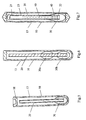
- a wiper provided by the invention comprises a rod 20 a wiping body 30 provided at one end of the rod and an outer packing, where in a non-exclusiveway said outer packing is a tube-like container 10 having both ends 11 and 12 closed permanently; the tube-like container 10 is provided with a circonferential easy break-off mark 13 at at least one place between both ends of the tube wall; and the rod 20 is of elasticity.
- Said circumferential easy break-off mark 13 in the longitudinal direction of the tube-like container 10 is such that other end 21 of the rod 20, which is opposite to said one end 22 of the rod 20 provided with the wiping body 30, extends beyond the cross section of the tube-like container 10 having the easy break-off mark 13, and when the tube-like container 10 is broken off along the easy break-off mark 13 into two parts 10a and 10b, the other end 21 is exposed out of the broken opening of the part 10b with the wiping body 30; and when the tube-like container 10 is broken-off along the easy break-off mark 13, a flexible deformation 20a of the rod 20 occurs under force without interfering with the breaking-off of the tube-like container 10, and the rod 20 can recover from the flexible deformation after said force that makes it deform is removed.
- Said tube-like container 10 is provided with an easy break-off mark 13 at one place near the middle of the tube wall between both ends 11 and 12.
- Said wiping body 30 comprises one kind of material selected from the group comprising: plant fiber, synthetic fiber, glutin sponge, sponge, soft high molecule absorbent material and brush-like article, and is provided at one end 22 of the rod 20 by one method selected from the group comprising: wounding, wrapping, clamping, shaping and interlinking, binding, and injection-molding integrally with the rod.
- this embodiment is the same as the first embodiment, except that said wiping body 30 is impregnated with working fluid.
- the third embodiment referring to Fig. 6 , this embodiment is the same as the first embodiment, except that said wiping body 30 provided at the end of the rod 20 is divided into two parts 30a and 30b along the axial direction of the rod.
- this embodiment is the same as the first embodiment, except that said rod 20 has a cavity containing working fluid 60, the end opening 21 closed by fusion, an easy break-off mark 23 provided at this end portion, and a lower end opening 22 blocked by silicone oil 40.
- the fifth embodiment referring to Fig. 8 , this embodiment is the same as the first embodiment, except that said rod 20 has a cavity containing working fluid 60, an upper end opening closed by fusion, an easy break-off mark 23 provided at this end portion, and a lower end opening 22 closed by a tube-like article 24, which is connected with an end portion of the tube-like container and one end of which is sealed.
- this embodiment is the same as the first embodiment, except that inside the tube-like container 10 there is a piston 70 whose diameter corresponds to the inner diameter of the tube-like container 10, and the tube-like container 10 contains working fluid 60 below the piston-like article 70, and on the inner wall of the tube-like container there are provided with three longitudinal slots 16 arranged equidistantly along the circumference.
- the seventh embodiment referring to Fig. 10 , this embodiment is the same as the first embodiment, except that inside the tube-like container 10 there is a spherical cap-like article 71, the outer diameter of which corresponds to the inner diameter of the tube-like container 10 and which is deformable when being subjected to a force.
- this embodiment is the same as the first embodiment, except that said tube-like container 10 stores therein at least two rods 20, with one end of each being provided with a wiping body 30.
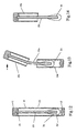
- the ninth embodiment referring to Figs. 12-14 , this embodiment is the same as the first embodiment, except that end 21 of the rod 20, opposite to the end provided with the wiping body 30, is fixedly coupled with an end portion 11 of the tube-like container 10.
- this embodiment is the same as the first or ninth embodiment, except that on the wall of said tube-like container 10 between both ends there are provided with easy break-off marks 13a and 13b at two places.
- this embodiment is the same as the first or ninth embodiment, except that in said wiping body 30 there is provided with one substance selected from the group comprising: working fluid 60, working powder 64 and working ointment 65.
- this embodiment is the same as the first or ninth embodiment, except that said wiping body 30 provided at one end of the rod 20 is divided into two parts 30a and 30b along the axial direction of the rod, both being impregnated with working fluid 60.
- this embodiment is the same as the first or ninth embodiment, except that said rod 20 has an easy break-off mark 23, an upper end connected with a sealing plug 18 which closes the upper end opening of the tube-like container 10 through fusion, and a lower end provided with a wiping body 30, which along the axial direction of the rod is divided into two parts 30a and 30b, part 30b being impregnated with working fluid.
- this embodiment is the same as the first or ninth embodiment, except that said rod 20 has a cavity containing working fluid 60, an end opening of the end provided with a wiping body 30 closed by a tube-like article 24 which is connected with an end portion of the tube-like container 10 and one end of which is sealed, a convex neck 25 provided at the upper portion and closing the upper end opening of the tube-like container 10 through fusion, and an easy break-off tail tube 26 which extends upwardly from the convex neck, its upper end opening being closed and its lower portion being provided with an easy break-off mark 23.
- this embodiment is the same as the first or ninth embodiment, except that said rod 20 has a cavity containing working fluid 60, and an end opening of the end 22 provided with wiping body 30 closed by a tube-like article 24, which is connected with an end portion of the tube-like container and one end of which is sealed.
- this embodiment is the same as the first or ninth embodiment, except that said rod 20 has a cavity containing working fluid 60, an upper end closed with the upper end opening of the tube-like container 10 through fusion, a middle portion connected with the tube-like container by a connecting member 27 which forms interference fit with the tube-like container, and an easy break-off mark 23 which is on the tube wall above the connecting member and corresponds to the easy break-off mark 13a on the outer wall of the tube-like container.
- this embodiment is the same as the first or ninth embodiment, except that on said rod 20 there is provided with at least one piston-like article 70, the diameter of which corresponds to the inner diameter of the tube-like container 10 and above which there are provided with three longitudinal slots 16 arranged equidistantly along the circumference of the inner wall of the tube-like container.
- the eighteenth embodiment referring to Fig. 29 , this embodiment is the same as the first or ninth embodiment, except that two wipers are paired up and connected with each other.
- the nineteenth embodiment referring to Fig. 30 , this embodiment is the same as the first or ninth embodiment, except that in the middle of the cavity of said tube-like container 10 there is provided with a plug-like article 19, which divides the cavity into two independent chambers.
- the first preparing method the ends of said tube-like container are closed permanently by using one of the following means: heat fusion with heat source, ultrasonic fusion, electromagnetic induction fusion, laser beam fusion, blocking with hot melt adhesive, binding, injection-molding and mechanical sealing.
- a preparing method of said wiper comprises the following steps: (1) extruding thermoplastic material into a tubing, cutting the tubing, and scratching an easy break-off mark thereon to form a tube-like container; (2) inserting a rod provided with a wiping body at one end thereof into the tube-like container; and (3) fusing and closing both ends of the tube-like container.
- the third preparing method comprises the following steps: (1) extruding a thermoplastic material into a tubing, cutting the tubing, and scratching an easy break-off mark to form a tube-like container; (2) inserting the rod provided with a wiping body at one end thereof into the tube-like container after the wiping body is impregnated with working fluid; and (3) heat fusing both ends of the tube-like container to close them, with one end of the rod fixedly coupled with one end of the tube-like container through fusion.
- a preparing method of said wiper comprises the following steps: (1) injection-molding thermoplastic material into a tube-like container with one end opened and the other end fused and closed, and into a sealing plug, the outer diameter of which corresponds to the inner diameter of the opening end; (2) after inserting the end of the rod opposite to the end provided with a wiping body into a socket pre-arranged inside the sealing plug, inserting the rod into the tube-like container; (3) by using one method selected from the group comprising: ultrasonic wave, electromagnetic induction, bonding and mechanical sealing, the opening end of the tube-like container being fixedly coupled with and closed by the sealing plug; and (4) scratching an easy break-off mark on the wall of the tube-like container.
- the fifth preparing method comprises the following steps: (1) injection-molding thermoplastic material into a tube-like container with one end opened and the other end fused and closed; (2) scratching an easy break-off mark; (3) filling the tube-like container with working fluid through its opening end; (4) inserting a rod with one end provided with a wiping body into the tube-like container; and (5) by using heating or hot melt adhesive, fusing and closing the opening end of the tube-like container, with one end of the rod being fixedly coupled with this end of the tube-like container through fusion.
- the invention makes full use of the characteristics of thermoplastic material, and delicately combines the structure, function, use and package of the product to make it become a novel product which is firm, airtight and capable of being opened easily, has a simple structure, and can be used conveniently.
- the invention advantageously integrates the function of the outer packing into the product itself, thus greatly improving the use performance of the product.
- the tube-like container having both ends sealed permanently is completely different from the conventional concept of bag type package, and comparing with a film packing bag, not only is firm, but also uses the principle of stress concentration, i.e.
- both ends of the tube-like container may be closed permanently to form a integral unit by using the technology such as fusion seal, mechanical seal and the like, and the wiping body, the rod as well as the working fluid etc.
- the end opening of the tube-like container is not permanently closed, that is, the end opening is closed by a seal member which may be pulled out upon use, whereas closing permanently in the present invention means that it is unnecessary or impossible to open the closed end openings of the tube-like container through a conventional method; secondly, taking out the wiping body from near the middle broken-off opening assure aseptic manipulation effectively during use.
- the wiping body 30 which optionally comprises a cotton plant fiber is connected to the lower end of the rod by wounding to form a conventional cotton swab.
- the cotton swab is placed into the tube-like container 10, both ends 11 and 12 of which are sealed by fusion.
- the cotton swab provided in the tube-like container may be sealed completely and stored aseptically for a long time after being sterilized; upon use, both hands respectively grasp the two ends of the tube-like container 10 and bend it slightly by force, as shown in Fig.
- the tube-like container 10 is broken off along the pre-arranged easy break-off mark 13 into two parts 10a and 10b, and the rod 20 having elasticity is deformed into a shape 20a under force and thus does not interfere with the breaking-off of the tube-like container 10, and since the upper end of the rod is higher than the cross section of the tube-like container having the easy break-off mark 13, the upper end of the rod is exposed out of the broken opening of the broken end 10b; the cotton swab is taken out as shown in Fig. 3 and can be used to wipe directly. In the whole process, both hands do not touch the end surface of near the middle broken opening of the tube-like container and the pulled-out cotton body, so that contamination is prevented.
- the wiping body such as cotton is impregnated with working fluid such as liquid medicine in advance, and after being exposed by breaking-off and unclosing, the wiping body 30 with liquid medicine can be used to wipe immediately.
- the wiping body 30 is divided into two parts. Upon use, part 30a is used to wipe for the first time and part 30b is used to wipe for the second time, thereby advantageously satisfying the use requirements of wiping for two times. According to requirements, the wiping body may also be divided into three or more parts.
- the rod 20 can employ natural material such as a bamboo rod, a wood rod and the like having good elasticity, or can use other suitable material.
- working fluid 60 dose not contact with the wiping body 30, so as to solve the problem that the wiping body 30 is not suitable for immersing into certain working fluid 60 for a long time.
- the tube-like container 10 is broken off and opened along the easy break-off mark 13 thereon, and then the upper end of the rod is broken off along the easy break-off mark 23 thereon, so that the upper end of the cavity of the rod is open to atmosphere, and the working fluid 60 passes through the silicone oil 40 by gravity, to flow out and wet down the wiping body 30, thereby using it immediately after being taken out.
- the tube-like container 10 Before use, since the tube-like container 10 has good air-tightness, the volatile molecules of the working fluid escapes through the silicone oil until a saturation pressure is reached in the closed cavity of the tube-like container, and therefore, the working fluid can be stored stably before use.
- this embodiment differs from the fourth embodiment in that: a tube-like article 24 is inserted into the lower end opening of the rod 20 which contains working fluid 60 inside the cavity, and an interference fit is formed therebetween so that the lower end opening is closed.
- the rod 20 is drawn upwards and is separated from the tube-like article 24 since the lower end of the tube-like article 24 is connected with the lower end of the tube-like container 10. Therefore, the lower end opening of the rod is opened and working fluid 60 flows out of the lower end opening to wet the wiping body 30, so the wiping body 30 can be used immediately after being taken out.
- Technology holes 15a and 15b are shown in Fig. 8 .
- This embodiment is very applicable to a case in which working fluid 60 is not suitable for contacting with viscous oil substances such as silicone oil.
- a piston-like article 70 which corresponds to the inner diameter of the cavity and separates the working fluid 60 from the wiping body 30.
- the tube-like container 10 is broken off, and the rod is pressed downward by grasping its end, so that the piston-like article 70 is displaced downward along the inner wall of the tube-like container, and the working fluid 60 flows out from longitudinal slots 16 under pressure to wet the wiping body 30.
- the rod when in use, the rod is pressed downwards by grasping its end, so that the spherical cap-like article 71 having elasticity would, due to its deformation while being displaced downwards by force, create a gap with the tube wall, allowing the working fluid 60 to flow out through the gap and wet down the wiping body 30.
- said tube-like container 10 stores therein at least two rods 20, with one end of each being provided with one wiping body 30, and after the tube-like container 10 is broken off at its middle portion, each of the broken parts has one wiping body 30; and the tube-like container also can store therein a plurality of wiping bodies 30.
- the wiping body 30 which optionally comprises for example cotton plant fiber is connected to the lower end of the rod by wounding to form a conventional cotton swab.
- This cotton swab is placed into the tube-like container 10, and the rod end 21 and tube-like container end 11 are fused concurrently. While the upper end of the tube-like container 10 is being sealed, the upper end 21 of the rod 20 is fixedly coupled with the upper end 11 of the tube-like container 10. Therefore, as shown in Fig.
- the cotton swab provided in the tube-like container is sealed and can be stored aseptically for a long time after being sterilized; upon use, both hands respectively grasp the two ends of the tube-like container 10 and bend it slightly, as shown in Fig. 13 , the tube-like container 10 is broken off along the pre-arranged easy break-off mark 13 into two parts 10a and 10b, and the rod 20 having elasticity is deformed into an elastic shape 20a under force and thus does not interfere with the breaking-off of the tube-like container 10; as shown in Fig.
- the product provided by this technical solution has two easy break-off marks 13a and 13b at two places symmetric with respect to the middle of the tube-like container 10, to allow the process for selecting the direction of the easy break-off mark during production to be omitted, so that the productivity is increased.
- the rod 20 can also use natural material such as a bamboo rod, a wood rod and the like having good elasticity, and the upper end of the rod can be embedded into the fused and closed upper end of the tube-like container to be fixedly coupled thereto.
- the wiping body such as cotton is impregnated with working fluid 60 such as liquid medicine in advance, and after being exposed due to break off and open, the wiping body 30 being impregnated with liquid medicine can be used to wipe the treated location directly; referring to Fig.
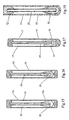
- the wiping body 30 is a kind of soft high molecule absorbent material, and after being shaped (presenting a hollow cylindrical shape), is interlinked with the lower end of the rod and placed into working powder 64, and an indicating mark 14 is provided near the easy break-off mark 13 at the upper portion of the tube-like container, so that in the case the tube-like container 10 is opaque, the end of the tube-like container 10 in which there is no wiping body 30 is grasped accurately by right hand or left hand according to use habit; referring to Fig. 19 , the wiping body 30 is a brush-like article which is held onto the lower end of the rod and immersed into working fluid 60 which can be detergent, glue and the like; referring to Fig.
- the wiping body 30 is a brush-like article of flat plate type which is inserted into the working ointment 65, injection-molded integrally with the rod 20 and provided at one end of the rod.
- the brush-like article of flat plate type can also be provided thereon with several small through-holes, so as to dip working fluid for wiping. Thus, different wiping use requirements can be satisfied and the use is more convenient.
- the wiping body 30 provided at one end of the rod 20 is divided along the axial direction of the rod into two parts 30a and 30b, both being impregnated with working fluid such as disinfectant, and upon use, part 30b is used to wipe and sterilize for the first time and part 30a is used to wipe and sterilize for the second time, thereby satisfying the use requirements, i.e. wiping two times for sterilization treatment; parts 30a and 30b may absorb the same working fluid, or different kinds of working fluid which preferably have the same or similar solvents.
- Fig. 24 of the thirteenth embodiment it can satisfy the use requirements that working fluid is removed by wiping after being applied.
- part 30b with liquid medicine is used to wipe a small wound, subsequently the surplus liquid medicine around the wound is removed by using part 30a, and then the wound is covered with a bandage or other covering materials in order to protect the wound.
- the rod 20 can be broken off along the easy break-off mark 23 provided thereon and the end with the wiping body is thrown away, so that most material can be recovered to reuse and the contaminated waste is reduced significantly, thus realizing environment protection; if necessary, other technical solutions of the invention can use similar measures for environment protection purpose.
- this technical solution not only allows working fluid 60 not contacting with the wiping body 30 before use, but also more importantly satisfies the production technology requirements, i.e. sterilizing at first, then filling the working fluid.
- the lower end opening of the rod 20 forms an interference fit with the tube-like article 24, which has a lower end free of cotton body 30 and connected with the lower end of the tube-like container through fusion; the convex neck 25 provided at the upper portion of rod closes the upper end opening of the tube-like container 10 through fusion by means of ultrasonic technology.
- the chamber containing the cotton body 30 After being subjected to sterilization treatment, the chamber containing the cotton body 30 is in aseptic state, and working fluid 60 is filled into the cavity of the rod 20 through the upper end opening of the easy break-off tail tube 26 which extends upwards from the upper convex neck 25 of the rod, and then the upper end opening of the easy break-off tail tube 26 is closed by fusion.
- the easy break-off tail tube 26 is broken off along the easy break-off mark 23, and the tube-like container 10 is broken off along the easy break-off mark 13, then the upper end of the tube-like container 10 is pulled upwards, so that the air-tight interference fit between the lower end opening of the rod 20 and the tube-like article 24 is broken, and working fluid 60 flows out of the lower end opening of the rod 20 to wet down the cotton body 30, which can be used immediately after being taken out.
- said easy break-off tail tube 26 can be covered with an ornament cap or a protect case.
- Fig. 26 of the fifteenth embodiment it is the same as the fourteenth embodiment except that the upper end of the rod 20 with its cavity containing working fluid 60 is connected with the upper end of the tube-like container 10, and need not be broken off to communicate with atmosphere upon use as long as the tube-like container 10 is broken off along the easy break-off mark 13 and the upper broken part is pulled upwards, and if the diameter of the cavity of the rod 20 is greater than 3.5 mm, the working fluid 60 would flow out of the lower end opening of the rod 20 to wet down the cotton body 30; if the inner diameter of the rod 20 is small or the working fluid is viscous and thick, the upper part of the tube-like container broken along the easy break-off mark 13 can be swung slightly, so that the working fluid 60 would be swung out of the lower end opening of the rod 20 to wet down the cotton body 30.
- Reference numerals 15a and 15b represent respectively the technology holes for production. This technical solution is especially suitable for the products which need relative large amount of working fluid, and can also satisfy the production technology requirements, i.e. firstly sterilizing, then filling working fluid. If necessary, longitudinal slots may be provided on the inner wall of the cavity of the rod 10, to facilitate working fluid 60 in the cavity of the rod to flow out rapidly.
- the easy break-off mark 13a at the upper portion of the tube-like container 10 and the easy break-off mark 23 at the upper portion of the rod 20 are about on the same level, and upon use the tube-like container 10 and the rod 20 can be broken off and opened simultaneously. Therefore, working fluid 60 in the cavity of the rod 20 would flow out of its lower through hole 29 to wet down the cotton body 30, and after that the tube-like container 10 is broken off along the easy break-off mark 13b thereon and the cotton body 30 is taken out for use.
- the tube-like container 10 is broken off along the easy break-off mark 13, and the piston-like article 70 is displaced upwards in the tube-like container 10, and when it reaches the longitudinal slots 16 on the inner wall of the tube-like container 10, the working fluid 60 will leak downward through the longitudinal slots 16 to wet down the cotton body 30.
- another piston-like article can be provided at a proper position above the piston-like article 70.
- the tube-like container 10 and the rod with the piston-like article 70 can be made by injection-molding.
- the wiping bodies can be selected as follows: neither contains working substances such as medicine; one does not contain medicine, but the other contains medicine; or both contain medicine, for example, one contains liquid medicine for cleaning and sterilizing a wound and the other contains certain biological glue for protecting the wound, thus, one can be used to clean and sterilize the wound and the biological glue of the other is applied to the wound for protecting. Different market requirements therefore can be satisfied.
- a plug-like article 19 is arranged in the middle of the cavity of the tube-like container 10 and divides the cavity into two independent chambers, one containing two wiping bodies with working fluid, and the other containing one wiping body, thus realizing the purpose that one tube has double uses.
- both ends of the tube-like container of the invention are closed by using simultaneously or respectively heating, ultrasonic wave, electromagnetic induction, injection-molding, hot melt adhesive, binding, mechanical sealing, and other technologies, which are all common known industrial techniques.
- both ends of the tube-like container are closed through heat fusing with heat source, and both ends of the tube-like container shown in Fig. 30 are fused by heating with heat source and kneaded; as in the third embodiment (see Fig.
- the lower end of the tube-like container is closed through fusion during the injection-molding thereof, and its upper end is closed through fusion with heat source; further as in the second embodiment (see Fig. 5 ) and the thirteen embodiment (see Fig. 24 ), the lower end of the tube-like container is closed through fusion during the injection-molding thereof, and its upper end is fused and closed by using ultrasonic means; further as in the eleventh embodiment (see Fig.
- the upper end of the rod and the upper end of the tube-like container form a mechanical seal in advance, and then the upper end surface of the tube-like container is fused and closed with heat produced by the electromagnetic induction foil 80 by using electromagnetic induction technology; further as in the sixteenth embodiment (see Fig. 27 ), the upper end of the rod and the upper end of the tube-like container are connected and closed by using hot melt adhesive; further as in the eleventh embodiment (see Fig. 19 ), the upper end of the rod and the upper end of the tube-like container are fixedly coupled together and closed by using adhesive. Further as in the eleventh embodiment (see Fig. 18 , Fig. 21 and Fig. 22 ), the upper end of the tube-like container adopts mechanical seal, as shown in Fig.
- the upper end opening of the tube-like container 10 is closed by a rubber plug 72, the upper end of the rod 20 is inserted into a connection hole at the lower portion of the rubber plug 72 so as to be fixedly coupled with the end of the tube-like container 10, and since the rubber plug 72 sinks into the upper end opening of the tube-like container 10 and can not be pulled out, the upper end is closed permanently; as shown in Fig.
- the upper end opening of the tube-like container 10 is closed by inserting the convex neck 25 which is injection-molded integrally with the rod 20 and has a cylindrical shape, and two round flanges 28 provided on the convex neck 25 correspond to and form an interference fit with two round slots 17 provided on the inner wall of the upper end of the tube-like container 10, so that the opening end of the tube-like container 10 is closed permanently; and as shown in Fig. 22 , the upper end opening of the tube-like container 10 is closed by the sealing plug 18, and its mechanical seal manner is similar to that shown in Fig. 21 . Other commonly known mechanical seal manners also can be selected to close the end opening of the tube-like container.
- the means of fixedly coupling the upper end of the rod with the upper end portion of the tube-like container described in the invention are as follows: integral fusion connection as shown in the ninth embodiment (see Fig. 12 ); the upper end of rod being inserted into the seal member fixedly coupled to the upper opening end of the tube-like container, as shown in Fig. 18 and Fig. 22 of the eleventh embodiment; and injection-molding integrally with the seal member inserted into the upper opening end of the tube-like container, as shown in Fig. 19 and Fig. 21 of the eleventh embodiment.
- the closing manners of both ends of the tube-like container, and the fixedly coupling manners of the upper end of rod with the upper end portion of the tube-like container can have various equivalent changes and combinations, for example, the fusion seal of the upper end portion of the tube-like container in the seventh embodiment (see Fig. 10 ) can be changed to mechanical seal and the like (such as inserting the rubber plug into the upper end opening of the tube-like container); and further the upper end of rod and the upper end portion of the tube-like container can be fixedly coupled together through mechanical connection and the like instead of integral fusion.
- the second to fifth preparing methods correspond to several representative technical solutions of the invention, and the preparing methods corresponding to other technical solutions can be selected with reference to them.
- the making materials of the tube-like container described in the invention need to have good thermoplastic property, and the high molecule materials such as polyethylene, polypropylene, PET and etc are suitable;
- the length of the tube-like container is preferably from 40 mm to 200 mm, the outer diameter is preferably from 5 mm to 15 mm, and the wall thickness is preferably from 0.5 mm to 2 mm;
- the easy break-off mark cut by a cutter on the tube wall preferably has a depth of 0.1 mm to 0.5 mm and a length around the whole circumference, so that the tube-like container can be broken off easily along the easy break-off mark on the tube wall in any direction, and further the broken opening is smooth and has no sharp corner to make the use more convenient and safer;
- the easy break-off mark on the tube wall also can be obtained by a mold when the tube-like container is injection
- the wiper provided by the invention integrates delicately the rod, the wiping body provided at one end of the rod, the tube-like container and its unclosing manner into a unit, which is firm, airtight and capable of being opened easily, can be used safely and regularly anywhere, facilitates aseptic manipulation, can be used and stored conveniently, has simple preparing methods and can satisfies different technology requirements, has low production cost, and can be applied widely.
- the tube-like container and the rod can be made selectively of same thermoplastic material such as high molecule materials, and also can be made selectively of different thermoplastic materials having proper fusion temperatures, and the rod can employ materials having good elasticity, such as bamboo rod, wood rod and the like; the tube-like container and the rod can also have different colors, so that in the case that one end of the rod is fixedly coupled with an end of the tube-like container through fusion, the color of the rod can be exposed from the closed end to facilitate recognition in production and use; for the carried working fluid such as liquid medicine, disinfectant, liquid cosmetics, washing liquid and the like, as well as various working powder like substance, ointment like substance, oil like substance, glue and the like, reasonable technical solutions can be selected according to the characteristics of working substances themselves and the market requirements; and also in the technical solutions of the fourth and thirteenth embodiments, other wound protecting materials such as bandages can be placed into the tube-like container, to make the consumers feel more convenient.
- other wound protecting materials such as bandages can be placed into the tube-like
- the bandages and other materials are deformable, the normal use of the tube-like container (breaking off) is not affected even though these kind of related articles are placed into its cavity.
- an rectangular-shape independent chamber which is formed integrally therewith for storing bandages and other wound protecting materials.
- the opening end of the independent chamber and the opening end of the tube-like container can be closed simultaneously, and the easy break-off mark of the independent chamber and the easy break-off mark on the tube-like container can be on the same level and connected with each other, so that they can be broken off simultaneously.
- the tube-like container On the outer wall of the tube-like container there are also printed with easy break-off mark, product name, production date and the like by spraying code, thermo-transferring, displacing printing, screen printing, and other technologies, and certain number of wipers may be stored in board paper boxes or package bags made of compound films, to facilitate storage and transportation, and use.
- the wiper provided by the invention not only can be used in medical treatment, but also can be applied widely in daily life, for example, the wiper provided with detergents can be conveniently used to clean recording magnetic heads, CD drives of computers, and other elements or devices.
- the preferred embodiments of the invention are not limited to those listed above, and the embodiments having various changes within the claims are all within the scope claimed by the invention; and the high molecule materials selected and used by the invention need to have good thermoplastic property, and various compound materials can be selected and used, which are intended to improve the tenacity, air tightness, environment protection, and other performances and are obtained by changing components, co-extruding multilayer, coating, secondary injection-molding and other technologies. It further needs to be explained that in the preferred embodiments listed by the invention, the ends of the tube-like container are closed mostly by using fusion manners, and both the reliability of the seal and the reasonability of the production technology are obvious.
- the related members are made by injection-molding technology, since the results of the mechanical seal are greatly affected by machining accuracy and assembling quality.
- the specific seal manners for closing the end opening of the tube-like container cannot be listed one by one in the invention.
- the outer configurations of the tube-like container also can be changed widely, with their purpose and substantive effects remain unchanged. Such alternative equivalent solutions are all within the scope claimed by the invention.
Landscapes
- Health & Medical Sciences (AREA)
- Public Health (AREA)
- Veterinary Medicine (AREA)
- Engineering & Computer Science (AREA)
- Biomedical Technology (AREA)
- Heart & Thoracic Surgery (AREA)
- Life Sciences & Earth Sciences (AREA)
- Animal Behavior & Ethology (AREA)
- General Health & Medical Sciences (AREA)
- Vascular Medicine (AREA)
- Epidemiology (AREA)
- Anesthesiology (AREA)
- Hematology (AREA)
- Media Introduction/Drainage Providing Device (AREA)
- Injection Moulding Of Plastics Or The Like (AREA)
- Sealing Material Composition (AREA)
- Medical Preparation Storing Or Oral Administration Devices (AREA)
- Medicinal Preparation (AREA)
- Perforating, Stamping-Out Or Severing By Means Other Than Cutting (AREA)
- Polishing Bodies And Polishing Tools (AREA)
- Packages (AREA)
Abstract
Description
- The invention relates to a wiping appliance for medical use and daily life use, and particularly, to a wiper and the preparing method thereof.
- In medical organizations and in daily life places, wiping appliances have been used more and more widely, in which a wiping body made of soft absorbent material is provided at one end of a rod body. The wiping appliance, such as cotton swabs, is used to wipe away secretions of human body or to sample; after having dipped and impregnated with working fluid such as liquid medicine, disinfectant, and the like, can be used to wipe and sterilize a wound or injection location of human body; also can be used to dip and absorb liquid cosmetic, ointment, powder or other substances for use; further can be used to dip detergent for cleaning; and so on. In recent years, a medicine-containing cotton swab in which a cotton body wound onto one end of a swab rod is impregnated with liquid medicine beforehand, a medicine-containing cotton ball without a rod, and a medicine-containing paper sheet or other products, are used more and more widely; further, a medicine-carrying cotton swab in which working fluid are beforehand filled into a tube-like rod body, and other products have also appeared in succession.
- The above products or technical solutions have drawbacks as follows:
- Products of cotton swab type have such problems as difficult aseptic manipulation, fragile package, inconvenient use etc. during their use. A conventional cotton swab is packed in a plastic film bag, or packed in a laminated foil pouch as described in
US6,494,856B1 . As show inFig. 1 ofUS6,494,856B1 , the perimeter of the foil pouch is sealed through heating and pressing to prevent any contamination of the contents. When needed, the sealed pouch can betorn along a line of weakness. In this case, the opening will be crimped, and a part of the outer face (contamination face) of the pouch turns inwardly and soils the opening. The cotton swab, when taken out through the torn opening, is readily susceptible to contact with the contaminated torn opening to be bacterium-contaminated, so that the use safety and the sampling accuracy of the cotton swab is disturbed This kind of package is not strung or firm due to thinness and thus is subject to breach. During transportation and storage, the cotton swab also would be damaged mechanically due to the infirm plastic film bag or be bacterium-contaminated due to the damage of the bag. Moreover, the foil edge may injure the skin of the user when he or she tries to tear the pouch. -
BR-8402976 Fig. 1 . the package is made from plastic sheets and dialytic paper through molding, and the perimeter is sealed by heating and pressing. The packaging material is very thin and thus is not strong or firm. The package is apt to breach and pollute. Additionally, the paper is not resistant to humidity. - The cotton swab within the package generally suffers from a problem as follows: the swab is prone to soil when it is removed from the torn opening.
US-2902146 seems to resolve this problem. As shown inFig. 1 , theswab 12 is enclosed within thesac 10 which is positioned within acasing 22 in the form of a soft tube, thecasting 22 is closed at both ends in a way similar to a toothpaste pouch. As shown inFig. 3 , a line ofseverance 28 extends transversely of thecasing 22 for severing the oneend portion 24 from thecasing 22 by a pair ofscissors 30, then thesac 10 containing theswab 12 is thrust out of the severedend portion 24 of thecasting 22, as shown inFig. 4 . At this time, theswab 12 remains sterile thanks to the protection of thesac 10. However, as shown inFig. 5 , in need of taking out theswab 12 through the foldedend portion 20 of thesac 10, thesec 10 is pulled toward the hand-heldportion 18 to expose theabsorbent tip 16. Since theshank 14 is shorter than the fingers and two hands should act on the swab simultaneously, the finder is prone to touch theabsorbent tip 16 to soil it, particularly during first aid when mal-manipulation may occur frequently. Additionally, double packages are used, and the casing has thick wall. Therefore, it is expensive to manufacture and not convenient for use. - In some products or technical solutions, the cotton swab is held in a test-tube-like container with a plug cap closing its tube entrance, and when being used, is taken out after the blocking cap is removed from this tube entrance, such that there is a contradiction that the plug cap should on the one hand seal the tube entrance closely and on the other hand be pulled out easily, thereby the sealing reliability or the use convenience being poor. For example, as shown in Fig. of
US-4586604 , theculture collection instrument 10 is closed with a shield protector element 15, which has a scored closedend portion 15a, which can snap open as shown inFig. 2 . Upon using, theend portion 15a is thrust to reveal theswab element 14 from the end of theculture collection instrument 10, as shown inFigs. 3 and 4 . One skilled in the art knows that this is a kind of mechanical seal, and various components must have tight seal therebetween to ensure the seal effect. In this solution, there must have tight seal between the shield protector element 15 and the end portion of thecultural collection instrument 10, and between the shield protector element 15 and its closedend portion 15a, as shown inFig. 2 . However this solution provides no other methods to take out the swab except that the two components which have formed secure fit therebetween are separated from each other. Obviously, the more firmly the two components are coupled together, the harder they can be separated. Additionally, in order to ensure the seal effect, there will be high demand on process accuracy, so the manufacture cost will be high. Moreover, the seal effect will be influenced upon temperature change and external force due to the plastic deformation of the high-molecule polymer material. In other words, the plastic parts have unstable mechanical seal results. - The same problem can be found in
US-4903708 . As shown inFigs. 1 and 3 , theend portion 60 of the storage chamber is mechanically sealed with thecan member 72, and thecap member 72 is drawn out via theend portion 60 when needed. InWO93/12421 Figs. 1 and thehousing base 14 and thehousing cap 16 are coupled with each other in a mechanical seal manner. Upon using, they are uncoupled at the seal joint and thus the swab can be taken out. These two solutions have the same defect in connection with the mechanical seal, such as complicated structure, high cost and unstable seal effect. - The medicine-containing cotton swab has not only problems similar to the cotton swab, but also a problem that the medicine can be volatilized easily. In particular for the medicine-containing cotton swabs packed with a plastic film and an aluminum foil-PVC foam cover, the solution immersed in the cotton body may volatilize and penetrate into the thin foam cover to deteriorate the product.
- Also, the technical solution for filling working fluid, such as liquid medicine and the like, into the rod body of the cotton swab has the same problems as those of the medicine-containing cotton swab, i.e. difficult aseptic manipulation, fragile package, inconvenient use, etc. Additionally, although the opening end of the rod is blocked with viscous substances such as silicone oil, the volatilization of the medicine cannot be prevented completely, because there are large gaps between the molecules of such viscous substances and thus the molecules of water, alcohol and the like in the working fluid can pass through those gaps easily; the medicine-containing cotton balls, the medicine-containing paper pieces and the like packed with compound film need to be held by clean article upon use, and thus have a disadvantage of requiring strict use environment and manipulation condition; and technical solutions described in some patents not only have a problem of non-tight package and closure, but also have a complex structure, an inconvenient use, and a high manufacture cost. They also have a disadvantage that the production technology requirements of filling the working fluid after sterilization cannot be satisfied, because some working fluid would deteriorate after being sterilized by ethylene oxide, cobalt-60 and the like. During the production of the working fluid-containing cotton swab, cotton ball and paper piece described above, if the cotton swab, cotton ball and paper piece are sterilized after being packed and then the sterilized and sealed package are opened again upon filing the working fluid, it would be contrary to the basic principle of the sterilizing technology.
- An object of the invention is to provide a solid and airtight wiper, which can be opened easily and used almost everywhere safely and regularly, and which facilitates aseptic manipulation and can be used and stored conveniently, and which can be manufactured simply with low cost, and which overcomes the drawbacks described above.
- Another object of the invention is to provide a wiper having the advantages of the products described above, which can prevent mal-manipulation and realize aseptic manipulation smoothly and can be used more conveniently and rapidly.
- A further object of the invention is to provide a wiper, which not only has the features of sealing, being opened easily and facilitating aseptic manipulation, but also can satisfy the production technology requirements, i.e. firstly sterilizing, secondly filling working fluid.
- A further object of the invention is to provide a preparing method of a wiper.
- In order to realize the object described above, the invention proposes a wiper as defined in enclosed claim 1.
- The invention can be further carried out by following measures:
- Said wiping body is impregnated with fluid.
- Said wiping body provided at the end of the rod is divided into two parts along the axial direction of the rod.
- Said rod has a cavity containing working fluid, the end of said rod provided with the wiping body closed by a tube-like article, one end of which is connected with an end portion of the tube-like container and sealed, and the other end of which forms interference fit with the end of the rod, the other end of said rod closed by fusion and provided with an easy break-off mark.
- The inside of the tube-like container is provided with a piston-like article whose diameter corresponds to the inner diameter of the tube-like container, and the tube-like container contains working fluid below the piston-like article, and there are three longitudinal slots arranged equidistantly along the circumference of the inner wall of the tube-like container.
- Inside the tube-like container there is a spherical cap-like article, the outer diameter of which corresponds to the inner diameter of the tube-like container and which is deformable when being subjected to a force.
- Said tube-like container stores therein at least two rods, with one end of each being provided with a wiping body.
- The other end of the rod, opposite to the end provided with the wiping body, is fixedly coupled with one end of the tube-like container.
- On the wall of said tube-like container between both ends there are provided with easy break-off marks at two places.
- The inside of said wiping body is provided with one substance selected from the group comprising: working fluid, working powder and working ointment.
- Said wiping body provided at the end of the rod is divided into two parts along the axial direction of the rod, both being impregnated with working fluid.
- Said rod has an easy break-off mark, the wiping body provided on the end of said rod along the axial direction of the rod is divided into two parts, one of them being impregnated with working fluid, while the end of the other part of said rod is coupled with a sealing plug which closes the top end opening of the tube-like container through fusion.
- Said rod has a cavity containing working fluid, an end opening of the end provided with the wiping body closed by a tube-like article, one end of which connected with an end portion of the tube-like container and sealed by fusion, and the other end of which forms interference fit with the rod, an easy break-off tail tube which extends upwardly from an convex neck provided at the top portion of the rod being closed at the top end opening thereof and being provided with an easy break-off mark at the bottom portion thereof.
- Said rod has a cavity containing working fluid, and an end opening of the end provided with the wiping body being closed by a tube-like article, one end of which is connected with an end portion of the tube-like container and sealed.
- Said rod has a cavity containing working fluid, the other end of said rod which is opposite to the end of said rod provided with the wiping body being closed with the top end opening of the tube-like container through fusion, a middle portion connected with the tube-like container by a connecting member which forms an interference fit with the tube-like container, and an easy break-off mark which is provided on the wall of the rod above the connecting member and corresponds to the easy break-off mark on the outer wall of the tube-like container, and other easy break-off marks may be provided on the outer wall of the tube-like container below the connecting member.
- On said rod there is provided with at least one piston-like article, the diameter of which corresponds to the inner diameter of the tube-like container, and above which there are provided with three longitudinal slots arranged equidistantly along the circumference of the inner wall of the tube-like container.
- Two wipers are paired up and connected with the tube-like container.
- In the middle of the cavity of said tube-like container there is provided with a plug-like article, which divides the cavity into two independent chambers.
- The end of said tube-like container is closed permanently by using one method selected from the group comprising: fusion by a heat source, ultrasonic fusion, electromagnetic induction fusion, laser beam fusion, blocking with hot melt adhesive, binding, injection-molding and mechanical sealing.
- A preparing method of said wiper comprises the following steps: (1) extruding thermoplastic material into a tubing, cutting the tubing, and scratching an easy break-off mark to form a tube-like container; (2) inserting a rod provided with a wiping body at one end thereof into the tube-like container; and (3) fusing and closing both ends of the tube-like container.
- A preparing method of said wiper comprises the following steps: (1) extruding thermoplastic material into a tubing, cutting the tubing, and scratching an easy break-off mark thereon to form a tube-like container; (2) inserting the rod into the tube-like container after the wiping body at one end thereof is impregnated with working fluid; and (3) heat fusing both ends of the tube-like container to close them, with one end of the rod fixedly coupled with one end of the tube-like container through fusion.
- A preparing method of said wiper comprises the following steps: (1) injection-molding thermoplastic material into a tube-like container with one end opened and the other end fused and closed, and into a sealing plug, the outer diameter of which corresponds to the inner diameter of the opening end; (2) after inserting an end of the rod opposite to the end provided with the wiping body into a socket pre-arranged inside the sealing plug, inserting the rod into the tube-like container; (3) by using one method selected from the group comprising: ultrasonic wave, electromagnetic induction, bonding and mechanical sealing, the opening end of the tube-like container being fixedly coupled with and closed by the sealing plug; and (4) scratching an easy break-off mark on the wall of the tube-like container.
- A preparing method of said wiper comprises the following steps: (1) injection-molding thermoplastic material into a tube-like container with one end opened and the other end fused and closed; (2) scratching an easy break-off mark thereon; (3) filling the tube-like container with working fluid through its opening end; (4) inserting a rod with one end provided with a wiping body into the tube-like container; and (5) by using heating or hot melt adhesive, fusing and closing the opening end of the tube-like container, with one end of the rod being fixedly coupled with said end of the tube-like container through fusion.
- The particular embodiments of the invention are explained below in details in conjunction with accompanying figures, in which:
-
Fig. 1 shows schematically an axially sectional view of a first embodiment of the invention in closed state; -
Fig. 2 shows schematically an axially sectional view of the first embodiment of the invention upon broken off; -
Fig. 3 shows schematically an axially sectional view of the first embodiment of the invention in use; -
Fig. 4 orFig. 5 shows schematically an axially sectional view of a second embodiment of the invention in closed state; -
Fig. 6 shows schematically an axially sectional view of a third embodiment of the invention in closed state; -
Fig. 7 shows schematically an axially sectional view of a fourth embodiment of the invention in closed state; -
Fig. 8 shows schematically an axially sectional view of a fifth embodiment of the invention in closed state; -
Fig. 9 shows schematically an axially sectional view of a sixth embodiment of the invention in closed state; -
Fig. 10 shows schematically an axially sectional view a seventh embodiment of the invention in closed state; -
Fig. 11 shows schematically an axially sectional view of an eighth embodiment of the invention in closed state; -
Fig. 12 shows schematically an axially sectional view of a ninth embodiment of the invention in closed state; -
Fig. 13 shows schematically an axially sectional view of the ninth embodiment of the invention upon broken-off; -
Fig. 14 shows schematically an axially sectional view the ninth embodiment of the invention in use; -
Fig. 15 shows schematically an axially sectional view of a tenth embodiment of the invention in closed state; -
Figs. 16-22 show schematically axially sectional views of an eleventh embodiment of the invention in closed state; -
Fig. 23 shows schematically an axially sectional view of a twelfth embodiment of the invention in closed state; -
Fig. 24 shows schematically an axially sectional view of a thirteenth embodiment of the invention in closed state; -
Fig. 25 shows schematically an axially sectional view of a fourteenth embodiment of the invention in closed state; -
Fig. 26 shows schematically an axially sectional view of a fifteenth embodiment of the invention in closed state; -
Fig. 27 shows schematically an axially sectional view of a sixteenth embodiment of the invention in closed state; -
Fig. 28 shows schematically an axially sectional view of a seventeenth embodiment of the invention in closed state; -
Fig. 29 shows schematically an axially sectional view of an eighteenth embodiment of the invention in closed state; and -
Fig. 30 shows schematically an axially sectional view of a nineteenth embodiment of the invention in closed state. - The names of various parts indicated by reference numbers in the drawings are:
- 10-a tube-like container 11-an upper end of the tube-like container 12-a lower end of the tube-like container 13-an easy break-off mark on the tube-like container 14-an indicating mark 15-a technology hole
- 16-a longitudinal slot 17-a round slot 18-a sealing plug 19-a plug-like article 20-a rod 21-an upper end of the rod22-a lower end of the rod 23-an easy break-off mark on the rod 24-a tube-like article
- 25-a convex neck 26-an easy break-off tail tube 27-a connecting member 28-a ring like flange 29-a through hole 30-a wiping body 40-silicone oil 60-working fluid 64-working powder
- 65-working ointment 70-a piston-like article 71-a spherical cap-like article 72-a rubber plug80-an electromagnetic induction foil
- 90-hot melt adhesive
- The first embodiment: referring to
Figs. 1-3 , a wiper provided by the invention comprises arod 20 a wipingbody 30 provided at one end of the rod and an outer packing, where in a non-exclusiveway said outer packing is a tube-like container 10 having both ends 11 and 12 closed permanently; the tube-like container 10 is provided with a circonferential easy break-off mark 13 at at least one place between both ends of the tube wall; and therod 20 is of elasticity. - Said circumferential easy break-
off mark 13 in the longitudinal direction of the tube-like container 10 is such thatother end 21 of therod 20, which is opposite to said oneend 22 of therod 20 provided with the wipingbody 30, extends beyond the cross section of the tube-like container 10 having the easy break-off mark 13, and when the tube-like container 10 is broken off along the easy break-off mark 13 into twoparts other end 21 is exposed out of the broken opening of thepart 10b with the wipingbody 30; and when the tube-like container 10 is broken-off along the easy break-off mark 13, aflexible deformation 20a of therod 20 occurs under force without interfering with the breaking-off of the tube-like container 10, and therod 20 can recover from the flexible deformation after said force that makes it deform is removed. - Said tube-
like container 10 is provided with an easy break-off mark 13 at one place near the middle of the tube wall between both ends 11 and 12. - Said wiping
body 30 comprises one kind of material selected from the group comprising: plant fiber, synthetic fiber, glutin sponge, sponge, soft high molecule absorbent material and brush-like article, and is provided at oneend 22 of therod 20 by one method selected from the group comprising: wounding, wrapping, clamping, shaping and interlinking, binding, and injection-molding integrally with the rod. - The second embodiment: referring to
Fig. 4 orFig. 5 , this embodiment is the same as the first embodiment, except that said wipingbody 30 is impregnated with working fluid. - The third embodiment: referring to
Fig. 6 , this embodiment is the same as the first embodiment, except that said wipingbody 30 provided at the end of therod 20 is divided into twoparts - The fourth embodiment: referring to
Fig. 7 , this embodiment is the same as the first embodiment, except that saidrod 20 has a cavity containing workingfluid 60, theend opening 21 closed by fusion, an easy break-off mark 23 provided at this end portion, and alower end opening 22 blocked bysilicone oil 40. - The fifth embodiment: referring to
Fig. 8 , this embodiment is the same as the first embodiment, except that saidrod 20 has a cavity containing workingfluid 60, an upper end opening closed by fusion, an easy break-off mark 23 provided at this end portion, and alower end opening 22 closed by a tube-like article 24, which is connected with an end portion of the tube-like container and one end of which is sealed. - The sixth embodiment: referring to
Fig. 9 , this embodiment is the same as the first embodiment, except that inside the tube-like container 10 there is apiston 70 whose diameter corresponds to the inner diameter of the tube-like container 10, and the tube-like container 10 contains workingfluid 60 below the piston-like article 70, and on the inner wall of the tube-like container there are provided with threelongitudinal slots 16 arranged equidistantly along the circumference. - The seventh embodiment: referring to
Fig. 10 , this embodiment is the same as the first embodiment, except that inside the tube-like container 10 there is a spherical cap-like article 71, the outer diameter of which corresponds to the inner diameter of the tube-like container 10 and which is deformable when being subjected to a force. - The eighth embodiment: referring to
Fig. 11 , this embodiment is the same as the first embodiment, except that said tube-like container 10 stores therein at least tworods 20, with one end of each being provided with a wipingbody 30. - The ninth embodiment: referring to
Figs. 12-14 , this embodiment is the same as the first embodiment, except thatend 21 of therod 20, opposite to the end provided with the wipingbody 30, is fixedly coupled with anend portion 11 of the tube-like container 10. - The tenth embodiment: referring to
Fig. 15 , this embodiment is the same as the first or ninth embodiment, except that on the wall of said tube-like container 10 between both ends there are provided with easy break-offmarks - The eleventh embodiment: referring to
Figs. 16-22 , this embodiment is the same as the first or ninth embodiment, except that in said wipingbody 30 there is provided with one substance selected from the group comprising: workingfluid 60, workingpowder 64 and workingointment 65. - The twelfth embodiment: referring to
Fig. 23 , this embodiment is the same as the first or ninth embodiment, except that said wipingbody 30 provided at one end of therod 20 is divided into twoparts fluid 60. - The thirteenth embodiment: referring to
Fig. 24 , this embodiment is the same as the first or ninth embodiment, except that saidrod 20 has an easy break-off mark 23, an upper end connected with a sealingplug 18 which closes the upper end opening of the tube-like container 10 through fusion, and a lower end provided with a wipingbody 30, which along the axial direction of the rod is divided into twoparts part 30b being impregnated with working fluid. - The fourteenth embodiment: referring to
Fig. 25 , this embodiment is the same as the first or ninth embodiment, except that saidrod 20 has a cavity containing workingfluid 60, an end opening of the end provided with a wipingbody 30 closed by a tube-like article 24 which is connected with an end portion of the tube-like container 10 and one end of which is sealed, aconvex neck 25 provided at the upper portion and closing the upper end opening of the tube-like container 10 through fusion, and an easy break-offtail tube 26 which extends upwardly from the convex neck, its upper end opening being closed and its lower portion being provided with an easy break-off mark 23. - The fifteenth embodiment: referring to
Fig. 26 , this embodiment is the same as the first or ninth embodiment, except that saidrod 20 has a cavity containing workingfluid 60, and an end opening of theend 22 provided with wipingbody 30 closed by a tube-like article 24, which is connected with an end portion of the tube-like container and one end of which is sealed. - The sixteenth embodiment: referring to
Fig. 27 , this embodiment is the same as the first or ninth embodiment, except that saidrod 20 has a cavity containing workingfluid 60, an upper end closed with the upper end opening of the tube-like container 10 through fusion, a middle portion connected with the tube-like container by a connectingmember 27 which forms interference fit with the tube-like container, and an easy break-off mark 23 which is on the tube wall above the connecting member and corresponds to the easy break-off mark 13a on the outer wall of the tube-like container. - The seventeenth embodiment: referring to
Fig. 28 , this embodiment is the same as the first or ninth embodiment, except that on saidrod 20 there is provided with at least one piston-like article 70, the diameter of which corresponds to the inner diameter of the tube-like container 10 and above which there are provided with threelongitudinal slots 16 arranged equidistantly along the circumference of the inner wall of the tube-like container. - The eighteenth embodiment: referring to
Fig. 29 , this embodiment is the same as the first or ninth embodiment, except that two wipers are paired up and connected with each other. - The nineteenth embodiment: referring to
Fig. 30 , this embodiment is the same as the first or ninth embodiment, except that in the middle of the cavity of said tube-like container 10 there is provided with a plug-like article 19, which divides the cavity into two independent chambers. - The first preparing method: the ends of said tube-like container are closed permanently by using one of the following means: heat fusion with heat source, ultrasonic fusion, electromagnetic induction fusion, laser beam fusion, blocking with hot melt adhesive, binding, injection-molding and mechanical sealing.
- The second preparing method: a preparing method of said wiper comprises the following steps: (1) extruding thermoplastic material into a tubing, cutting the tubing, and scratching an easy break-off mark thereon to form a tube-like container; (2) inserting a rod provided with a wiping body at one end thereof into the tube-like container; and (3) fusing and closing both ends of the tube-like container.
- The third preparing method: a preparing method of said wiper comprises the following steps: (1) extruding a thermoplastic material into a tubing, cutting the tubing, and scratching an easy break-off mark to form a tube-like container; (2) inserting the rod provided with a wiping body at one end thereof into the tube-like container after the wiping body is impregnated with working fluid; and (3) heat fusing both ends of the tube-like container to close them, with one end of the rod fixedly coupled with one end of the tube-like container through fusion.
- The fourth preparing method: a preparing method of said wiper comprises the following steps: (1) injection-molding thermoplastic material into a tube-like container with one end opened and the other end fused and closed, and into a sealing plug, the outer diameter of which corresponds to the inner diameter of the opening end; (2) after inserting the end of the rod opposite to the end provided with a wiping body into a socket pre-arranged inside the sealing plug, inserting the rod into the tube-like container; (3) by using one method selected from the group comprising: ultrasonic wave, electromagnetic induction, bonding and mechanical sealing, the opening end of the tube-like container being fixedly coupled with and closed by the sealing plug; and (4) scratching an easy break-off mark on the wall of the tube-like container.
- The fifth preparing method: a preparing method of said wiper comprises the following steps: (1) injection-molding thermoplastic material into a tube-like container with one end opened and the other end fused and closed; (2) scratching an easy break-off mark; (3) filling the tube-like container with working fluid through its opening end; (4) inserting a rod with one end provided with a wiping body into the tube-like container; and (5) by using heating or hot melt adhesive, fusing and closing the opening end of the tube-like container, with one end of the rod being fixedly coupled with this end of the tube-like container through fusion.
- The invention makes full use of the characteristics of thermoplastic material, and delicately combines the structure, function, use and package of the product to make it become a novel product which is firm, airtight and capable of being opened easily, has a simple structure, and can be used conveniently. The invention advantageously integrates the function of the outer packing into the product itself, thus greatly improving the use performance of the product. The tube-like container having both ends sealed permanently is completely different from the conventional concept of bag type package, and comparing with a film packing bag, not only is firm, but also uses the principle of stress concentration, i.e. providing an easy break-off mark on the tube wall of the tube-like container, to open the tube-like container, so that the product can be opened and used quite conveniently; the characteristics that the rod can be deformed elastically allow the tube-like container being broken off easily along the pre-arranged easy break-off mark and allow the rod resuming its original shape and function; the solution for fixedly coupling one end of the rod to one end of the tube-like container completely eliminates mis-manipulation during the use of the product, and greatly improves the use convenience and rapidity of the product; the design that the tube-like container is broken off at its middle portion and the wiping body is taken out from the broken-off opening at this middle portion, especially has a feature which not only allows the product to be used conveniently and rapidly but also brings about the following prominent advantages: firstly, both ends of the tube-like container may be closed permanently to form a integral unit by using the technology such as fusion seal, mechanical seal and the like, and the wiping body, the rod as well as the working fluid etc. provided in the container are sealed tightly and thus can be stored safely for a long time, thereby overcoming the disadvantages, such as complex seal structure, unstable effects, inconvenient unclosing etc. in the conventional technical solutions, in which the end opening of the tube-like container is not permanently closed, that is, the end opening is closed by a seal member which may be pulled out upon use, whereas closing permanently in the present invention means that it is unnecessary or impossible to open the closed end openings of the tube-like container through a conventional method; secondly, taking out the wiping body from near the middle broken-off opening assure aseptic manipulation effectively during use.
- Referring to
Figs. 1-3 of the first embodiment, the wipingbody 30 which optionally comprises a cotton plant fiber is connected to the lower end of the rod by wounding to form a conventional cotton swab. The cotton swab is placed into the tube-like container 10, both ends 11 and 12 of which are sealed by fusion. Thus, as shown inFig. 1 , the cotton swab provided in the tube-like container may be sealed completely and stored aseptically for a long time after being sterilized; upon use, both hands respectively grasp the two ends of the tube-like container 10 and bend it slightly by force, as shown inFig. 2 , the tube-like container 10 is broken off along the pre-arranged easy break-off mark 13 into twoparts rod 20 having elasticity is deformed into ashape 20a under force and thus does not interfere with the breaking-off of the tube-like container 10, and since the upper end of the rod is higher than the cross section of the tube-like container having the easy break-off mark 13, the upper end of the rod is exposed out of the broken opening of thebroken end 10b; the cotton swab is taken out as shown inFig. 3 and can be used to wipe directly. In the whole process, both hands do not touch the end surface of near the middle broken opening of the tube-like container and the pulled-out cotton body, so that contamination is prevented. - Referring to
Fig. 4 orFig. 5 of the second embodiment, the wiping body such as cotton is impregnated with working fluid such as liquid medicine in advance, and after being exposed by breaking-off and unclosing, the wipingbody 30 with liquid medicine can be used to wipe immediately. - Referring to
Fig. 6 of the third embodiment, the wipingbody 30 is divided into two parts. Upon use,part 30a is used to wipe for the first time andpart 30b is used to wipe for the second time, thereby advantageously satisfying the use requirements of wiping for two times. According to requirements, the wiping body may also be divided into three or more parts. Therod 20 can employ natural material such as a bamboo rod, a wood rod and the like having good elasticity, or can use other suitable material. - Referring to
Fig. 7 of the fourth embodiment, workingfluid 60 dose not contact with the wipingbody 30, so as to solve the problem that the wipingbody 30 is not suitable for immersing into certain workingfluid 60 for a long time. When in use, the tube-like container 10 is broken off and opened along the easy break-off mark 13 thereon, and then the upper end of the rod is broken off along the easy break-off mark 23 thereon, so that the upper end of the cavity of the rod is open to atmosphere, and the workingfluid 60 passes through thesilicone oil 40 by gravity, to flow out and wet down the wipingbody 30, thereby using it immediately after being taken out. Before use, since the tube-like container 10 has good air-tightness, the volatile molecules of the working fluid escapes through the silicone oil until a saturation pressure is reached in the closed cavity of the tube-like container, and therefore, the working fluid can be stored stably before use. - Referring to
Fig. 8 of the fifth embodiment, this embodiment differs from the fourth embodiment in that: a tube-like article 24 is inserted into the lower end opening of therod 20 which contains workingfluid 60 inside the cavity, and an interference fit is formed therebetween so that the lower end opening is closed. Upon use, therod 20 is drawn upwards and is separated from the tube-like article 24 since the lower end of the tube-like article 24 is connected with the lower end of the tube-like container 10. Therefore, the lower end opening of the rod is opened and workingfluid 60 flows out of the lower end opening to wet the wipingbody 30, so the wipingbody 30 can be used immediately after being taken out.Technology holes Fig. 8 . This embodiment is very applicable to a case in which workingfluid 60 is not suitable for contacting with viscous oil substances such as silicone oil. - Referring to
Fig. 9 of the sixth embodiment, inside the tube-like container 10 there is a piston-like article 70 which corresponds to the inner diameter of the cavity and separates the workingfluid 60 from the wipingbody 30. When in use, the tube-like container 10 is broken off, and the rod is pressed downward by grasping its end, so that the piston-like article 70 is displaced downward along the inner wall of the tube-like container, and the workingfluid 60 flows out fromlongitudinal slots 16 under pressure to wet the wipingbody 30. - Referring to
Fig. 10 of the seventh embodiment, for the product provided by this technical solution, when in use, the rod is pressed downwards by grasping its end, so that the spherical cap-like article 71 having elasticity would, due to its deformation while being displaced downwards by force, create a gap with the tube wall, allowing the workingfluid 60 to flow out through the gap and wet down the wipingbody 30. - Referring to
Fig. 11 of the eighth embodiment, said tube-like container 10 stores therein at least tworods 20, with one end of each being provided with one wipingbody 30, and after the tube-like container 10 is broken off at its middle portion, each of the broken parts has one wipingbody 30; and the tube-like container also can store therein a plurality of wipingbodies 30. - Referring to
Figs. 12-14 of the ninth embodiment, the wipingbody 30 which optionally comprises for example cotton plant fiber is connected to the lower end of the rod by wounding to form a conventional cotton swab. This cotton swab is placed into the tube-like container 10, and therod end 21 and tube-like container end 11 are fused concurrently. While the upper end of the tube-like container 10 is being sealed, theupper end 21 of therod 20 is fixedly coupled with theupper end 11 of the tube-like container 10. Therefore, as shown inFig. 12 , the cotton swab provided in the tube-like container is sealed and can be stored aseptically for a long time after being sterilized; upon use, both hands respectively grasp the two ends of the tube-like container 10 and bend it slightly, as shown inFig. 13 , the tube-like container 10 is broken off along the pre-arranged easy break-off mark 13 into twoparts rod 20 having elasticity is deformed into anelastic shape 20a under force and thus does not interfere with the breaking-off of the tube-like container 10; as shown inFig. 14 , since the upper end of therod 20 has been fixedly coupled to the upper end of the tube-like container, the hand grasping theupper part 10a of the tube-like container need not move and thelower end 10b can be removed conveniently by the other hand grasping it, then the wipingbody 30 is exposed to be directly used for wiping. This solution allows the product and its package into an integral unit, and since not only the product itself is firm and airtight, and can be opened conveniently, but also both hands have no repeated or undesired actions, both hands never touch the end surfaces of the broken opening of the tube-like container and the wiping body taken out from this broken opening to cause contamination, thus the mis-manipulation in use are prevented and the use speed of the product is improved greatly. When in use, sincepart 10a of the tube-like container is much thicker than the rod of the cotton swab, the grasping is more convenient so as to facilitate the rotation of the cotton body and the wiping. - Referring to
Fig. 15 of the tenth embodiment, the product provided by this technical solution has two easy break-offmarks like container 10, to allow the process for selecting the direction of the easy break-off mark during production to be omitted, so that the productivity is increased. Therod 20 can also use natural material such as a bamboo rod, a wood rod and the like having good elasticity, and the upper end of the rod can be embedded into the fused and closed upper end of the tube-like container to be fixedly coupled thereto. - Referring to
Fig. 16, Fig.18 ,Fig. 21 and Fig. 22 of the eleventh embodiment, the wiping body such as cotton is impregnated with working fluid 60 such as liquid medicine in advance, and after being exposed due to break off and open, the wiping body 30 being impregnated with liquid medicine can be used to wipe the treated location directly; referring toFig. 17 , the wiping body 30 is a kind of soft high molecule absorbent material, and after being shaped (presenting a hollow cylindrical shape), is interlinked with the lower end of the rod and placed into working powder 64, and an indicating mark 14 is provided near the easy break-off mark 13 at the upper portion of the tube-like container, so that in the case the tube-like container 10 is opaque, the end of the tube-like container 10 in which there is no wiping body 30 is grasped accurately by right hand or left hand according to use habit; referring toFig. 19 , the wiping body 30 is a brush-like article which is held onto the lower end of the rod and immersed into working fluid 60 which can be detergent, glue and the like; referring toFig. 20 , the wiping body 30 is a brush-like article of flat plate type which is inserted into the working ointment 65, injection-molded integrally with the rod 20 and provided at one end of the rod. The brush-like article of flat plate type can also be provided thereon with several small through-holes, so as to dip working fluid for wiping. Thus, different wiping use requirements can be satisfied and the use is more convenient. - Referring to
Fig. 23 of the twelfth embodiment, the wipingbody 30 provided at one end of therod 20 is divided along the axial direction of the rod into twoparts part 30b is used to wipe and sterilize for the first time andpart 30a is used to wipe and sterilize for the second time, thereby satisfying the use requirements, i.e. wiping two times for sterilization treatment;parts - Referring to
Fig. 24 of the thirteenth embodiment, it can satisfy the use requirements that working fluid is removed by wiping after being applied. For example,part 30b with liquid medicine is used to wipe a small wound, subsequently the surplus liquid medicine around the wound is removed by usingpart 30a, and then the wound is covered with a bandage or other covering materials in order to protect the wound. Having been used, therod 20 can be broken off along the easy break-off mark 23 provided thereon and the end with the wiping body is thrown away, so that most material can be recovered to reuse and the contaminated waste is reduced significantly, thus realizing environment protection; if necessary, other technical solutions of the invention can use similar measures for environment protection purpose. - Referring to
Fig. 25 of the fourteenth embodiment, this technical solution not only allows workingfluid 60 not contacting with the wipingbody 30 before use, but also more importantly satisfies the production technology requirements, i.e. sterilizing at first, then filling the working fluid. The lower end opening of therod 20 forms an interference fit with the tube-like article 24, which has a lower end free ofcotton body 30 and connected with the lower end of the tube-like container through fusion; theconvex neck 25 provided at the upper portion of rod closes the upper end opening of the tube-like container 10 through fusion by means of ultrasonic technology. After being subjected to sterilization treatment, the chamber containing thecotton body 30 is in aseptic state, and workingfluid 60 is filled into the cavity of therod 20 through the upper end opening of the easy break-offtail tube 26 which extends upwards from the upperconvex neck 25 of the rod, and then the upper end opening of the easy break-offtail tube 26 is closed by fusion. Upon use, the easy break-offtail tube 26 is broken off along the easy break-off mark 23, and the tube-like container 10 is broken off along the easy break-off mark 13, then the upper end of the tube-like container 10 is pulled upwards, so that the air-tight interference fit between the lower end opening of therod 20 and the tube-like article 24 is broken, and workingfluid 60 flows out of the lower end opening of therod 20 to wet down thecotton body 30, which can be used immediately after being taken out. If necessary, said easy break-offtail tube 26 can be covered with an ornament cap or a protect case. - Referring to
Fig. 26 of the fifteenth embodiment, it is the same as the fourteenth embodiment except that the upper end of therod 20 with its cavity containing workingfluid 60 is connected with the upper end of the tube-like container 10, and need not be broken off to communicate with atmosphere upon use as long as the tube-like container 10 is broken off along the easy break-off mark 13 and the upper broken part is pulled upwards, and if the diameter of the cavity of therod 20 is greater than 3.5 mm, the workingfluid 60 would flow out of the lower end opening of therod 20 to wet down thecotton body 30; if the inner diameter of therod 20 is small or the working fluid is viscous and thick, the upper part of the tube-like container broken along the easy break-off mark 13 can be swung slightly, so that the workingfluid 60 would be swung out of the lower end opening of therod 20 to wet down thecotton body 30.Reference numerals rod 10, to facilitate workingfluid 60 in the cavity of the rod to flow out rapidly. - Referring to
Fig. 27 of the sixteenth embodiment, the easy break-off mark 13a at the upper portion of the tube-like container 10 and the easy break-off mark 23 at the upper portion of therod 20 are about on the same level, and upon use the tube-like container 10 and therod 20 can be broken off and opened simultaneously. Therefore, workingfluid 60 in the cavity of therod 20 would flow out of its lower throughhole 29 to wet down thecotton body 30, and after that the tube-like container 10 is broken off along the easy break-off mark 13b thereon and thecotton body 30 is taken out for use. - Referring to
Fig. 28 of the seventeenth embodiment, for the product provided by this technical solution, the tube-like container 10 is broken off along the easy break-off mark 13, and the piston-like article 70 is displaced upwards in the tube-like container 10, and when it reaches thelongitudinal slots 16 on the inner wall of the tube-like container 10, the workingfluid 60 will leak downward through thelongitudinal slots 16 to wet down thecotton body 30. In order to prevent workingfluid 60 from splashing out of the upper portion due to possible mis-manipulation, another piston-like article can be provided at a proper position above the piston-like article 70. The tube-like container 10 and the rod with the piston-like article 70 can be made by injection-molding. - Referring to
Fig. 29 of the eighteenth embodiment, two wipers are connected with each other either axially or side by side. The wiping bodies can be selected as follows: neither contains working substances such as medicine; one does not contain medicine, but the other contains medicine; or both contain medicine, for example, one contains liquid medicine for cleaning and sterilizing a wound and the other contains certain biological glue for protecting the wound, thus, one can be used to clean and sterilize the wound and the biological glue of the other is applied to the wound for protecting. Different market requirements therefore can be satisfied. - Referring to
Fig. 30 of the nineteenth embodiment, a plug-like article 19 is arranged in the middle of the cavity of the tube-like container 10 and divides the cavity into two independent chambers, one containing two wiping bodies with working fluid, and the other containing one wiping body, thus realizing the purpose that one tube has double uses. - Referring to the first preparing method, according to the structure characteristics, the sequence of the process, the production cost etc., both ends of the tube-like container of the invention are closed by using simultaneously or respectively heating, ultrasonic wave, electromagnetic induction, injection-molding, hot melt adhesive, binding, mechanical sealing, and other technologies, which are all common known industrial techniques. As in the first embodiment (see
Fig. 1 ), the twelfth embodiment (seeFig. 23 ), and the nineteenth embodiment (seeFig. 30 ), both ends of the tube-like container are closed through heat fusing with heat source, and both ends of the tube-like container shown inFig. 30 are fused by heating with heat source and kneaded; as in the third embodiment (seeFig. 6 ) and the sixth embodiment (seeFig. 9 ), the lower end of the tube-like container is closed through fusion during the injection-molding thereof, and its upper end is closed through fusion with heat source; further as in the second embodiment (seeFig. 5 ) and the thirteen embodiment (seeFig. 24 ), the lower end of the tube-like container is closed through fusion during the injection-molding thereof, and its upper end is fused and closed by using ultrasonic means; further as in the eleventh embodiment (seeFig. 20 ), the upper end of the rod and the upper end of the tube-like container form a mechanical seal in advance, and then the upper end surface of the tube-like container is fused and closed with heat produced by the electromagnetic induction foil 80 by using electromagnetic induction technology; further as in the sixteenth embodiment (seeFig. 27 ), the upper end of the rod and the upper end of the tube-like container are connected and closed by using hot melt adhesive; further as in the eleventh embodiment (seeFig. 19 ), the upper end of the rod and the upper end of the tube-like container are fixedly coupled together and closed by using adhesive. Further as in the eleventh embodiment (seeFig. 18 ,Fig. 21 and Fig. 22 ), the upper end of the tube-like container adopts mechanical seal, as shown inFig. 18 , the upper end opening of the tube-like container 10 is closed by a rubber plug 72, the upper end of the rod 20 is inserted into a connection hole at the lower portion of the rubber plug 72 so as to be fixedly coupled with the end of the tube-like container 10, and since the rubber plug 72 sinks into the upper end opening of the tube-like container 10 and can not be pulled out, the upper end is closed permanently; as shown inFig. 21 , the upper end opening of the tube-like container 10 is closed by inserting the convex neck 25 which is injection-molded integrally with the rod 20 and has a cylindrical shape, and two round flanges 28 provided on the convex neck 25 correspond to and form an interference fit with two round slots 17 provided on the inner wall of the upper end of the tube-like container 10, so that the opening end of the tube-like container 10 is closed permanently; and as shown inFig. 22 , the upper end opening of the tube-like container 10 is closed by the sealing plug 18, and its mechanical seal manner is similar to that shown inFig. 21 . Other commonly known mechanical seal manners also can be selected to close the end opening of the tube-like container. The means of fixedly coupling the upper end of the rod with the upper end portion of the tube-like container described in the invention are as follows: integral fusion connection as shown in the ninth embodiment (seeFig. 12 ); the upper end of rod being inserted into the seal member fixedly coupled to the upper opening end of the tube-like container, as shown inFig. 18 andFig. 22 of the eleventh embodiment; and injection-molding integrally with the seal member inserted into the upper opening end of the tube-like container, as shown inFig. 19 and Fig. 21 of the eleventh embodiment. Of course, the closing manners of both ends of the tube-like container, and the fixedly coupling manners of the upper end of rod with the upper end portion of the tube-like container can have various equivalent changes and combinations, for example, the fusion seal of the upper end portion of the tube-like container in the seventh embodiment (seeFig. 10 ) can be changed to mechanical seal and the like (such as inserting the rubber plug into the upper end opening of the tube-like container); and further the upper end of rod and the upper end portion of the tube-like container can be fixedly coupled together through mechanical connection and the like instead of integral fusion. - The second to fifth preparing methods correspond to several representative technical solutions of the invention, and the preparing methods corresponding to other technical solutions can be selected with reference to them. The making materials of the tube-like container described in the invention need to have good thermoplastic property, and the high molecule materials such as polyethylene, polypropylene, PET and etc are suitable; the length of the tube-like container is preferably from 40 mm to 200 mm, the outer diameter is preferably from 5 mm to 15 mm, and the wall thickness is preferably from 0.5 mm to 2 mm; the easy break-off mark cut by a cutter on the tube wall preferably has a depth of 0.1 mm to 0.5 mm and a length around the whole circumference, so that the tube-like container can be broken off easily along the easy break-off mark on the tube wall in any direction, and further the broken opening is smooth and has no sharp corner to make the use more convenient and safer; the easy break-off mark on the tube wall also can be obtained by a mold when the tube-like container is injection-molded, or can be obtained by changing the performances such as fragility of the partial material of the tube-like container.
- To sum up, the wiper provided by the invention integrates delicately the rod, the wiping body provided at one end of the rod, the tube-like container and its unclosing manner into a unit, which is firm, airtight and capable of being opened easily, can be used safely and regularly anywhere, facilitates aseptic manipulation, can be used and stored conveniently, has simple preparing methods and can satisfies different technology requirements, has low production cost, and can be applied widely. The tube-like container and the rod can be made selectively of same thermoplastic material such as high molecule materials, and also can be made selectively of different thermoplastic materials having proper fusion temperatures, and the rod can employ materials having good elasticity, such as bamboo rod, wood rod and the like; the tube-like container and the rod can also have different colors, so that in the case that one end of the rod is fixedly coupled with an end of the tube-like container through fusion, the color of the rod can be exposed from the closed end to facilitate recognition in production and use; for the carried working fluid such as liquid medicine, disinfectant, liquid cosmetics, washing liquid and the like, as well as various working powder like substance, ointment like substance, oil like substance, glue and the like, reasonable technical solutions can be selected according to the characteristics of working substances themselves and the market requirements; and also in the technical solutions of the fourth and thirteenth embodiments, other wound protecting materials such as bandages can be placed into the tube-like container, to make the consumers feel more convenient. Since the bandages and other materials are deformable, the normal use of the tube-like container (breaking off) is not affected even though these kind of related articles are placed into its cavity. Also by extruding, injection-molding or other technologies, on the outer wall of the tube-like container there is simultaneously provided with an rectangular-shape independent chamber which is formed integrally therewith for storing bandages and other wound protecting materials. The opening end of the independent chamber and the opening end of the tube-like container can be closed simultaneously, and the easy break-off mark of the independent chamber and the easy break-off mark on the tube-like container can be on the same level and connected with each other, so that they can be broken off simultaneously. On the outer wall of the tube-like container there are also printed with easy break-off mark, product name, production date and the like by spraying code, thermo-transferring, displacing printing, screen printing, and other technologies, and certain number of wipers may be stored in board paper boxes or package bags made of compound films, to facilitate storage and transportation, and use. The wiper provided by the invention not only can be used in medical treatment, but also can be applied widely in daily life, for example, the wiper provided with detergents can be conveniently used to clean recording magnetic heads, CD drives of computers, and other elements or devices.
- It needs to be noted that the preferred embodiments of the invention are not limited to those listed above, and the embodiments having various changes within the claims are all within the scope claimed by the invention; and the high molecule materials selected and used by the invention need to have good thermoplastic property, and various compound materials can be selected and used, which are intended to improve the tenacity, air tightness, environment protection, and other performances and are obtained by changing components, co-extruding multilayer, coating, secondary injection-molding and other technologies. It further needs to be explained that in the preferred embodiments listed by the invention, the ends of the tube-like container are closed mostly by using fusion manners, and both the reliability of the seal and the reasonability of the production technology are obvious. If the mechanical seal manner is applied, it is preferred that the related members are made by injection-molding technology, since the results of the mechanical seal are greatly affected by machining accuracy and assembling quality. Of course, the specific seal manners for closing the end opening of the tube-like container cannot be listed one by one in the invention. Further, the outer configurations of the tube-like container also can be changed widely, with their purpose and substantive effects remain unchanged. Such alternative equivalent solutions are all within the scope claimed by the invention.
Claims (18)
- A wiper, comprising a rod (20), a wiping body (30) provided at one end (22) of the rod (20) and an outer packing, characterized in that said outer packing is a tube-like container (10) having both ends (11, 12) closed permanently; the tube-like container (10) is provided with a circumferential easy break-off mark (13) on the tube wall between the both ends(11, 12) thereof, the position of the easy break-off mark (13) in the longitudinal direction of the tube-like container (10) is such that other end (21) of the rod (20) which is opposite to said one end (22) of the rod (20) provided with the wiping body (30) extends beyond the cross section of the tube-like container (10) having the easy break-offmark (13), and when the tube-like container (10) is broken off alone the easy break-off mark (13) into two parts (10a, 10b), the other end (21) is exposed out of the broken opening of the parts (10b) with the wining body (30); and when the tube-like container (10) is broken off along the easy break-off mark (13), a flexible deformation (20a) of the rod (20) occurs under force without interfering with the breaking-off of the tube-like container (10), and the rod (20) can recover from the flexible deformation after after said force that makes it deform is removed.
- The wiper according to claim 1, characterized in that said wiping body (30) is impregnated with working fluid (60).
- The wiper according to claim 1, characterized in that said wiping body (30) provided at the end (22) of the rod (20) is divided into two parts (30a, 30b) along the axial direction of the rod (20).
- The wiper according to claim 1, characterized in that said rod (20) has a cavity containing working fluid (60), the end (22) of said rod (20) provided with the wiping body (30) closed by a tube-like article (24), one end of which is connected with an end portion of the tube-like container (10) and sealed, and the other end of which forms interference fit with the end (22) of the rod (20), the other end (21) of said rod (20) closed by fusion and provided with an easy break-off mark.
- The wiper according to claim 1, characterized in that inside the tube-like container (10) there is provided with a piston-like article (70) whose diameter corresponds to the inner diameter of the tube-like container (10), and the tube-like container (10) contains working fluid (60) below the piston-like article (70), and there are three longitudinal slots (16) arranged equidistantly along the circumference of the inner wall of the tube-like container (10).
- The wiper according to claim 1, characterized in that inside the tube-like container (10) there is a spherical cap-like article (71), the outer diameter of which corresponds to the inner diameter of the tube-like container (10) and which is deformable under force.
- The wiper according to claim 1, characterized in that said tube-like container (10) stores at least two rods (20) therein, one end of each rod (20) being provided with a wiping body (30).
- The wiper according to claim 1, characterized in that the other end of the rod (20), opposite to the end provided with the wiping body (30), is fixedly coupled with an end portion of the tube-like container (10).
- The wiper according to claim 1 or claim 8, characterized in that on the wall of the tube-like container (10) between both ends there are provided with easy break-off marks (13) at two places.
- The wiper according to claim 1or claim 8, characterized in that inside the wiping body (30) there is provided with one of the following substance: working fluid (60), working powder (64) and working ointment (65).
- The wiper according to claim 1 or claim 8, characterized in that along the axial direction of the rod (20), said wiping body (30) provided at the end of the rod (20) is divided into two parts, both being impregnated with working fluid (60).
- The wiper according to claim 1 or claim 8, characterized in that said rod (20) has an easy break-off mark, the wiping body (30) provided on the end (22) of said rod (20), along the axial direction of the rod(20) is divided into two parts, one of them being impregnated with working fluid (60), the other end (21) of said rod (20) coupled with a sealing plug (18) which closes the top end opening of the tube-like container (10) through fusion.
- The wiper according to claim 1 or claim 8, characterized in that said rod (20) has a cavity containing working fluid (60), an end opening of the end provided with the wiping body (30) closed by a tube-like article (24), one end of which is connected with an end portion of the tube-like container (10) and sealed, and the other end of which forms interference fit with the rod (20), an easy break-off tail tube (26) which extends upwardly from an convex neck (25) provided at the top portion of the rod (20) being closed at the top end opening thereof and being provided with an easy break-off mark at the bottom portion thereof.
- The wiper according to claim 1 or claim 8, characterized in that said rod (20) has a cavity containing working fluid (60), and an end opening of the end provided with the wiping body (30) being closed by a tube-like article (24), one end of which is connected with an end portion of the tube-like container (10) and sealed.
- The wiper according to claim 1 or claim 8, characterized in that said rod (20) has a cavity containing working fluid (60), the other end (21) of said rod (20) which is opposite to the end (22) of said rod (20) provided with the wiping body (30) being closed with the top end opening of the tube-like container (10) through fusion, a middle portion connected with the tube-like container (10) by a connecting member (27) which forms an interference fit with the tube-like container (10), and an easy break-off mark (23) which is provided on the wall of the rod (20) above the connecting member (27) and corresponds to the easy break-off mark (13a) on the outer wall of the tube-like container (10), and other easy break-off marks (13b) may be provided on the outer wall of the tube-like container (10) below the connecting member (27).
- The wiper according to claim 1 or claim 8, characterized in that on said rod (20) there is provided with at least one piston-like article (70), the diameter of which corresponds to the inner diameter of the tube-like contailier (10) and above which there are provided with three longitudinal slots (16) arranged equidistantly along the circumference of the inner wall of the tube-like container (10).
- The wiper according to claim 1 or claim 8, characterized in that two wipers are paired up and connected with the tube-like container (10).
- The wiper according to claim 1 or claim 8, characterized in that in the middle of the cavity of said tube-like container (10) there is provided with a plug-like article (19), which divides the cavity into two independent chambers.
Applications Claiming Priority (3)
| Application Number | Priority Date | Filing Date | Title |
|---|---|---|---|
| CN 200310121777 CN1631346A (en) | 2003-12-23 | 2003-12-23 | An easy-to-open wiper |
| CN 200310121778 CN1631349A (en) | 2003-12-23 | 2003-12-23 | An easy-to-open integral wiper |
| PCT/CN2004/001453 WO2005060905A1 (en) | 2003-12-23 | 2004-12-14 | Swab and producing method thereof |
Publications (3)
| Publication Number | Publication Date |
|---|---|
| EP1707169A1 EP1707169A1 (en) | 2006-10-04 |
| EP1707169A4 EP1707169A4 (en) | 2007-06-06 |
| EP1707169B1 true EP1707169B1 (en) | 2010-01-27 |
Family
ID=34712076
Family Applications (1)
| Application Number | Title | Priority Date | Filing Date |
|---|---|---|---|
| EP04802466A Expired - Lifetime EP1707169B1 (en) | 2003-12-23 | 2004-12-14 | Swab and producing method thereof |
Country Status (7)
| Country | Link |
|---|---|
| US (1) | US8740831B2 (en) |
| EP (1) | EP1707169B1 (en) |
| JP (1) | JP4584267B2 (en) |
| AT (1) | ATE456346T1 (en) |
| DE (1) | DE602004025381D1 (en) |
| ES (1) | ES2340929T3 (en) |
| WO (1) | WO2005060905A1 (en) |
Families Citing this family (34)
| Publication number | Priority date | Publication date | Assignee | Title |
|---|---|---|---|---|
| US9085378B2 (en) * | 2004-05-18 | 2015-07-21 | Unidose Systems, Inc. | Tube filling process for liquid filled cotton swabs |
| US10226607B1 (en) * | 2006-04-03 | 2019-03-12 | American Medical Corporation | Daneshvar special medication pads, suppositories and methods |
| NL2000125C2 (en) * | 2006-07-04 | 2008-01-07 | Behrouz Farhoudi | Cleaning rod. |
| US20080058676A1 (en) * | 2006-09-06 | 2008-03-06 | Yong Peter A K | Retractable segmented bio-molecular collector swab system |
| US20090198183A1 (en) * | 2006-11-03 | 2009-08-06 | Krumme John F | Apparatus and methods for injecting dermal fillers |
| RU2332196C1 (en) * | 2006-11-21 | 2008-08-27 | Игорь Алексеевич Золотов | Antiseptic processing kit |
| US8485356B2 (en) * | 2008-02-06 | 2013-07-16 | Intra Vena, LLC | Methods for exposing and using a swab |
| CA2723149A1 (en) * | 2008-05-01 | 2009-11-05 | David A. Tesini | Two-person linking biometric identification device and methods of use thereof |
| JP4944070B2 (en) * | 2008-07-31 | 2012-05-30 | 株式会社アグリス | Chemical solution application kit |
| US20100181224A1 (en) * | 2009-01-21 | 2010-07-22 | An-Kung Kuo | Makeup Product Having a Lower Cost of Fabrication |
| JP5295081B2 (en) * | 2009-11-20 | 2013-09-18 | 栄研化学株式会社 | Sample collection instrument set |
| JP5299918B2 (en) * | 2009-11-20 | 2013-09-25 | 栄研化学株式会社 | Sample collection instrument set |
| US20110160635A1 (en) * | 2009-12-24 | 2011-06-30 | Baschnagel Robert J | Cotton balls, cotton swabs and cotton swab holder |
| US8943641B2 (en) * | 2010-06-03 | 2015-02-03 | Linden Photonics, Inc. | Method and apparatus for cleaning a fiber optic connector end face |
| US8551031B2 (en) * | 2011-05-03 | 2013-10-08 | Colson Edme | Swab applicator and methods of use |
| MX2013012916A (en) * | 2011-05-06 | 2013-11-21 | Bayer Consumer Care Ag | Stick pack with applicator. |
| JP6131007B2 (en) * | 2012-07-31 | 2017-05-17 | 株式会社イノアックコーポレーション | Method for producing cosmetic applicator and cosmetic applicator |
| DE102012024355A1 (en) * | 2012-12-13 | 2014-06-18 | Testo Ag | Sample treatment apparatus has swab which is movably arranged from outer side of liquid chamber to closure stopper during use position |
| KR101596029B1 (en) * | 2013-10-13 | 2016-02-19 | (주)포브코리아 | Ear pick emitted sequentially disposable swab |
| US9249561B2 (en) * | 2014-05-15 | 2016-02-02 | Cheng-Hsuan Wu | Anti-freeze faucet structure |
| BR112017013174A2 (en) * | 2014-12-18 | 2018-01-02 | 3M Innovative Properties Company | diaper accessories and related methods |
| CN106031683A (en) * | 2015-03-16 | 2016-10-19 | 吴竟哲 | Wiper convenient for high-efficiency production and production technology thereof |
| US10159824B2 (en) * | 2016-05-24 | 2018-12-25 | Joseph Trznadel | Multi-chamber container apparatuses and methods of making and using the same |
| US20210339274A1 (en) * | 2017-06-21 | 2021-11-04 | Michelle Duchnowski | Tubular holder |
| JP6563473B2 (en) * | 2017-12-26 | 2019-08-21 | 有限会社サプライズ | Cotton swab manufacturing method |
| USD892614S1 (en) | 2018-06-11 | 2020-08-11 | Ecolab Usa Inc. | Cap for container |
| JP2020044117A (en) * | 2018-09-19 | 2020-03-26 | 博康 久保田 | Cotton swab |
| CN109745081A (en) * | 2019-03-20 | 2019-05-14 | 领因生物科技(上海)有限公司 | Sampling swab |
| US11684520B1 (en) * | 2019-04-29 | 2023-06-27 | Robert E. Fischell | System and method for treating nasal bleeding |
| IT201900013623A1 (en) * | 2019-08-01 | 2021-02-01 | G M C S R L | Threaded capsule, particularly for cosmetic product bottles. |
| WO2021211509A1 (en) * | 2020-04-13 | 2021-10-21 | Argos Corporation | Swab and method of manufacturing a swab |
| CN114906458A (en) * | 2021-02-06 | 2022-08-16 | 临沂凯行医疗科技有限公司 | Cotton swab box with honeycomb type disinfection liquid tank and manufacturing method thereof |
| US12558524B2 (en) | 2022-03-18 | 2026-02-24 | Sage Products, Llc | Preoperative skin preparation applicator |
| CN117138214A (en) * | 2023-08-04 | 2023-12-01 | 济南明然医疗器械有限公司 | Disposable medical medicine carrying stick |
Family Cites Families (61)
| Publication number | Priority date | Publication date | Assignee | Title |
|---|---|---|---|---|
| US1573648A (en) * | 1925-02-24 | 1926-02-16 | Joseph H Sheely | Container |
| US2902146A (en) * | 1957-05-24 | 1959-09-01 | George O Doherty | Sterile package |
| US3923604A (en) * | 1971-04-26 | 1975-12-02 | M & H Plastics Inc | Tubular articles |
| US3818911A (en) * | 1972-05-11 | 1974-06-25 | E Fournier | Medicament and swab type applicators |
| US3792699A (en) * | 1972-05-30 | 1974-02-19 | Medex Inc | Disposable swab unit |
| US4206843A (en) * | 1978-06-15 | 1980-06-10 | Rainey Rhett K | Cauterizing system |
| US4211323A (en) * | 1978-12-01 | 1980-07-08 | California Medical Developments, Inc. | Disposable diagnostic swab having a stored culture medium |
| JPS55114644U (en) * | 1979-02-06 | 1980-08-13 | ||
| GB2059992B (en) | 1979-10-11 | 1983-10-19 | Pike B R | Culture-collecting kit and a method of taking a culture sample utilising it |
| US4387725A (en) * | 1981-02-10 | 1983-06-14 | Mull John D | Device for use in the collection and transportation of medical specimens |
| US4492305A (en) | 1983-07-08 | 1985-01-08 | Marion Laboratories, Inc. | Package for collecting cultures |
| US4657869A (en) * | 1984-05-18 | 1987-04-14 | E. I. Du Pont De Nemours And Company | Self-contained device for carrying out specific binding assays |
| US4586604A (en) * | 1984-06-28 | 1986-05-06 | Continental Plastic Corporation | Culture collection instrument and sealed swab holder therefor |
| US4600328A (en) * | 1985-10-15 | 1986-07-15 | Brenda Clements | Mascara applicator |
| ZA869277B (en) * | 1986-02-03 | 1987-08-26 | Chesebrough Ponds | Liquid dispenser with absorbent applicator tip |
| US4747719A (en) * | 1986-07-28 | 1988-05-31 | Cole Parkin | Swab applicator |
| US4707450A (en) * | 1986-09-25 | 1987-11-17 | Nason Frederic L | Specimen collection and test unit |
| US4733784A (en) * | 1986-11-17 | 1988-03-29 | R.J.S. Industries, Inc. | Container and applicator for fluids |
| US4711354A (en) * | 1986-12-09 | 1987-12-08 | Kjs Industries, Inc. | Article dispenser for lipstick or the like |
| US5250412A (en) * | 1987-03-23 | 1993-10-05 | Diamedix Corporation | Swab device and method for collecting and analyzing a sample |
| US4813432A (en) | 1987-10-13 | 1989-03-21 | Saint-Amand Manufacturing, Inc. | Swab transport system |
| US5266266A (en) * | 1988-02-09 | 1993-11-30 | Nason Frederic L | Specimen test unit |
| US4978504A (en) | 1988-02-09 | 1990-12-18 | Nason Frederic L | Specimen test unit |
| US5084005A (en) * | 1988-07-13 | 1992-01-28 | Becton, Dickinson And Company | Swab for collection of biological samples |
| US4952204A (en) * | 1988-08-10 | 1990-08-28 | Gam-Med Packaging Corporation | Dry handle swab assembly and unit |
| CA1338916C (en) | 1988-11-28 | 1997-02-18 | Elmer Felix Saint-Amand | Swab transport apparatus |
| AU611003B2 (en) * | 1988-12-23 | 1991-05-30 | Saint Amand Manufacturing, Inc. | Swab transport apparatus |
| EP0572637B1 (en) | 1990-12-13 | 2000-03-29 | NASON, Frederic L. | Specimen test unit |
| DE9111775U1 (en) | 1991-09-20 | 1992-02-20 | Ritter, Ralf, 8900 Augsburg | Swab kit for taking and transporting swab samples |
| CA2086659C (en) * | 1992-01-15 | 1999-01-12 | Paul H. Hanifl | Swab impregnating and dispensing system |
| JPH0672876U (en) * | 1993-03-27 | 1994-10-11 | ツサオ チィーン−ウア | Liquid storage tubular container and its new packaging form |
| JPH08666A (en) * | 1994-06-24 | 1996-01-09 | Heiwa Medeiku Kk | Swab |
| US5611361A (en) * | 1995-06-14 | 1997-03-18 | Revlon Consumer Products Corporation | Mascara application system |
| US5826600A (en) * | 1997-09-29 | 1998-10-27 | National Healthcare Products, Ltd. | Disposable dry-handle mascara applicator assembly |
| JP3357617B2 (en) * | 1999-02-05 | 2002-12-16 | 東京パフ株式会社 | Cosmetic applicator and manufacturing method thereof |
| JP2000343879A (en) * | 1999-06-03 | 2000-12-12 | Mitsubishi Pencil Co Ltd | Fluid applicator |
| FR2796532B1 (en) * | 1999-07-22 | 2002-02-01 | Oreal | DEVICE FOR APPLYING A LIQUID, PASTY OR POWDERY PRODUCT COMPRISING TWISTED FIBERS, AND APPLICATION ASSEMBLY THUS EQUIPPED |
| JP2001096970A (en) * | 1999-09-30 | 2001-04-10 | Pentel Corp | Liquid storage container for liquid ejector |
| US6516947B1 (en) * | 2000-08-11 | 2003-02-11 | Viridian Packaging Solutions, Llc | Containers having a fracture recess for opening the containers |
| US6503013B2 (en) | 2000-10-13 | 2003-01-07 | Pedinol Pharmacal Inc. | Method for applying a medicament and swab applicator for use therewith |
| CN1352922A (en) | 2000-11-15 | 2002-06-12 | 吴振东 | Composite cotton swab opened by kneading it for medical purpose or daily life |
| CN2474117Y (en) * | 2001-03-14 | 2002-01-30 | 吴振东 | Self carrying liquid connect-disconnect assembled type scrubber |
| US6592280B2 (en) * | 2001-04-20 | 2003-07-15 | 3M Innovative Properties Company | Container and applicator assembly |
| JP2002315779A (en) * | 2001-04-23 | 2002-10-29 | Heiwa Medic Co Ltd | Liquid impregnated swab |
| US6406451B1 (en) * | 2001-05-24 | 2002-06-18 | Zila, Inc. | Dry handle swab assembly |
| US6494856B1 (en) * | 2001-09-12 | 2002-12-17 | Unilever Home & Personal Care Usa, Division Of Conopco, Inc. | Swab deliverable actives |
| US6357947B1 (en) * | 2001-09-26 | 2002-03-19 | Phillip Mark | Applicator having a break away cup |
| JP3966755B2 (en) * | 2002-04-03 | 2007-08-29 | 白十字株式会社 | Sanitary material container |
| JP2003339767A (en) * | 2002-05-23 | 2003-12-02 | Suzuki Yushi Kogyo Kk | Cleaning swab for nostril |
| US6702113B2 (en) * | 2002-06-11 | 2004-03-09 | Anthony J. Marino | Toothbrush sanitizing assembly |
| US20030233063A1 (en) * | 2002-06-13 | 2003-12-18 | Sanyo Co., Ltd. | Applicator and application method |
| AU2003266159A1 (en) * | 2002-09-16 | 2004-04-30 | Zicam, Llc. | System and method for delivering a composition to the nasal membrane |
| US20040099543A1 (en) * | 2002-11-25 | 2004-05-27 | Garry Tsaur | Sealed container |
| US6957958B2 (en) * | 2003-04-02 | 2005-10-25 | Centrix, Inc. | Unit dose applicator with material chamber |
| WO2005013847A1 (en) * | 2003-07-07 | 2005-02-17 | Garry Tsaur | Packaging for oral hygiene devices |
| US20050019087A1 (en) * | 2003-07-25 | 2005-01-27 | Garry Tsaur | Enclosed applicator |
| US20050040164A1 (en) * | 2003-08-20 | 2005-02-24 | Garry Tsaur | Connector means |
| AU2003284935B2 (en) * | 2003-10-24 | 2006-12-21 | Garry Tsaur | Multiple applicators |
| US7112062B2 (en) * | 2003-12-05 | 2006-09-26 | 3M Innovative Properties Co. | Dental material storage and delivery system and method |
| US20060020238A1 (en) * | 2004-07-21 | 2006-01-26 | Garry Tsaur | Applicator with interchangeable inserts |
| US20060282035A1 (en) * | 2005-06-10 | 2006-12-14 | Peter Battisti | Cyanoacrylate adhesive applicator swab |
-
2004
- 2004-12-14 US US10/584,488 patent/US8740831B2/en active Active
- 2004-12-14 DE DE602004025381T patent/DE602004025381D1/en not_active Expired - Lifetime
- 2004-12-14 AT AT04802466T patent/ATE456346T1/en not_active IP Right Cessation
- 2004-12-14 EP EP04802466A patent/EP1707169B1/en not_active Expired - Lifetime
- 2004-12-14 WO PCT/CN2004/001453 patent/WO2005060905A1/en not_active Ceased
- 2004-12-14 ES ES04802466T patent/ES2340929T3/en not_active Expired - Lifetime
- 2004-12-14 JP JP2006545888A patent/JP4584267B2/en not_active Expired - Fee Related
Also Published As
| Publication number | Publication date |
|---|---|
| ES2340929T3 (en) | 2010-06-11 |
| US20080119776A1 (en) | 2008-05-22 |
| WO2005060905A1 (en) | 2005-07-07 |
| JP4584267B2 (en) | 2010-11-17 |
| US8740831B2 (en) | 2014-06-03 |
| ATE456346T1 (en) | 2010-02-15 |
| EP1707169A4 (en) | 2007-06-06 |
| JP2007515234A (en) | 2007-06-14 |
| EP1707169A1 (en) | 2006-10-04 |
| DE602004025381D1 (en) | 2010-03-18 |
Similar Documents
| Publication | Publication Date | Title |
|---|---|---|
| US8740831B2 (en) | Wiper and the preparing method thereof | |
| JP6072758B2 (en) | Medical device package and method for producing medical device package | |
| CN104870329B (en) | Sealing system and method of manufacture | |
| EP0172711A2 (en) | Packaging | |
| US6695515B1 (en) | Disposable multi-compartment applicator | |
| JP4230278B2 (en) | Package and fluid adhesion method | |
| US7478962B2 (en) | Device for packaging and application of a product | |
| KR20170085683A (en) | Disposable wet tissue with liquid bag | |
| JP5674467B2 (en) | Fluid substance storage container and its lid | |
| JP2666961B2 (en) | Dispenser applicator for coating substances | |
| KR101914007B1 (en) | Sealing label for cosmetic container | |
| CN100387210C (en) | wiper | |
| US9943157B1 (en) | Swab applicator with dispensing passage | |
| KR101956823B1 (en) | Blister package having applicator | |
| US4413754A (en) | Dispenser of small quantities of liquids | |
| KR200316761Y1 (en) | The blister package | |
| JPH11115954A (en) | Cap seal fitted with top plate | |
| CA2469557A1 (en) | Enclosed applicator | |
| JP4998793B2 (en) | Packaging container | |
| JP7549568B2 (en) | Trial applicator and manufacturing method for trial applicator | |
| JP2006115976A (en) | Swab package | |
| CN101001787B (en) | Infused Packaging and Infused Parts | |
| CN203598223U (en) | Single-plug combination cover and infusion container with same | |
| KR20240001501U (en) | Container for mask pack | |
| JPH04122369A (en) | Liquid coating device |
Legal Events
| Date | Code | Title | Description |
|---|---|---|---|
| PUAI | Public reference made under article 153(3) epc to a published international application that has entered the european phase |
Free format text: ORIGINAL CODE: 0009012 |
|
| 17P | Request for examination filed |
Effective date: 20060722 |
|
| AK | Designated contracting states |
Kind code of ref document: A1 Designated state(s): AT BE BG CH CY CZ DE DK EE ES FI FR GB GR HU IE IS IT LI LT LU MC NL PL PT RO SE SI SK TR |
|
| DAX | Request for extension of the european patent (deleted) | ||
| A4 | Supplementary search report drawn up and despatched |
Effective date: 20070507 |
|
| 17Q | First examination report despatched |
Effective date: 20070814 |
|
| GRAP | Despatch of communication of intention to grant a patent |
Free format text: ORIGINAL CODE: EPIDOSNIGR1 |
|
| GRAS | Grant fee paid |
Free format text: ORIGINAL CODE: EPIDOSNIGR3 |
|
| GRAA | (expected) grant |
Free format text: ORIGINAL CODE: 0009210 |
|
| AK | Designated contracting states |
Kind code of ref document: B1 Designated state(s): AT BE BG CH CY CZ DE DK EE ES FI FR GB GR HU IE IS IT LI LT LU MC NL PL PT RO SE SI SK TR |
|
| REG | Reference to a national code |
Ref country code: GB Ref legal event code: FG4D |
|
| REG | Reference to a national code |
Ref country code: CH Ref legal event code: EP |
|
| REG | Reference to a national code |
Ref country code: IE Ref legal event code: FG4D |
|
| REF | Corresponds to: |
Ref document number: 602004025381 Country of ref document: DE Date of ref document: 20100318 Kind code of ref document: P |
|
| REG | Reference to a national code |
Ref country code: CH Ref legal event code: NV Representative=s name: BUGNION S.A. |
|
| REG | Reference to a national code |
Ref country code: SE Ref legal event code: TRGR |
|
| REG | Reference to a national code |
Ref country code: NL Ref legal event code: VDEP Effective date: 20100127 |
|
| REG | Reference to a national code |
Ref country code: ES Ref legal event code: FG2A Ref document number: 2340929 Country of ref document: ES Kind code of ref document: T3 |
|
| LTIE | Lt: invalidation of european patent or patent extension |
Effective date: 20100127 |
|
| PG25 | Lapsed in a contracting state [announced via postgrant information from national office to epo] |
Ref country code: AT Free format text: LAPSE BECAUSE OF FAILURE TO SUBMIT A TRANSLATION OF THE DESCRIPTION OR TO PAY THE FEE WITHIN THE PRESCRIBED TIME-LIMIT Effective date: 20100127 |
|
| PG25 | Lapsed in a contracting state [announced via postgrant information from national office to epo] |
Ref country code: PT Free format text: LAPSE BECAUSE OF FAILURE TO SUBMIT A TRANSLATION OF THE DESCRIPTION OR TO PAY THE FEE WITHIN THE PRESCRIBED TIME-LIMIT Effective date: 20100527 Ref country code: NL Free format text: LAPSE BECAUSE OF FAILURE TO SUBMIT A TRANSLATION OF THE DESCRIPTION OR TO PAY THE FEE WITHIN THE PRESCRIBED TIME-LIMIT Effective date: 20100127 Ref country code: LT Free format text: LAPSE BECAUSE OF FAILURE TO SUBMIT A TRANSLATION OF THE DESCRIPTION OR TO PAY THE FEE WITHIN THE PRESCRIBED TIME-LIMIT Effective date: 20100127 Ref country code: IS Free format text: LAPSE BECAUSE OF FAILURE TO SUBMIT A TRANSLATION OF THE DESCRIPTION OR TO PAY THE FEE WITHIN THE PRESCRIBED TIME-LIMIT Effective date: 20100527 |
|
| PG25 | Lapsed in a contracting state [announced via postgrant information from national office to epo] |
Ref country code: SI Free format text: LAPSE BECAUSE OF FAILURE TO SUBMIT A TRANSLATION OF THE DESCRIPTION OR TO PAY THE FEE WITHIN THE PRESCRIBED TIME-LIMIT Effective date: 20100127 Ref country code: PL Free format text: LAPSE BECAUSE OF FAILURE TO SUBMIT A TRANSLATION OF THE DESCRIPTION OR TO PAY THE FEE WITHIN THE PRESCRIBED TIME-LIMIT Effective date: 20100127 Ref country code: FI Free format text: LAPSE BECAUSE OF FAILURE TO SUBMIT A TRANSLATION OF THE DESCRIPTION OR TO PAY THE FEE WITHIN THE PRESCRIBED TIME-LIMIT Effective date: 20100127 |
|
| PG25 | Lapsed in a contracting state [announced via postgrant information from national office to epo] |
Ref country code: RO Free format text: LAPSE BECAUSE OF FAILURE TO SUBMIT A TRANSLATION OF THE DESCRIPTION OR TO PAY THE FEE WITHIN THE PRESCRIBED TIME-LIMIT Effective date: 20100127 Ref country code: GR Free format text: LAPSE BECAUSE OF FAILURE TO SUBMIT A TRANSLATION OF THE DESCRIPTION OR TO PAY THE FEE WITHIN THE PRESCRIBED TIME-LIMIT Effective date: 20100428 Ref country code: EE Free format text: LAPSE BECAUSE OF FAILURE TO SUBMIT A TRANSLATION OF THE DESCRIPTION OR TO PAY THE FEE WITHIN THE PRESCRIBED TIME-LIMIT Effective date: 20100127 Ref country code: CY Free format text: LAPSE BECAUSE OF FAILURE TO SUBMIT A TRANSLATION OF THE DESCRIPTION OR TO PAY THE FEE WITHIN THE PRESCRIBED TIME-LIMIT Effective date: 20100127 |
|
| PG25 | Lapsed in a contracting state [announced via postgrant information from national office to epo] |
Ref country code: SK Free format text: LAPSE BECAUSE OF FAILURE TO SUBMIT A TRANSLATION OF THE DESCRIPTION OR TO PAY THE FEE WITHIN THE PRESCRIBED TIME-LIMIT Effective date: 20100127 Ref country code: CZ Free format text: LAPSE BECAUSE OF FAILURE TO SUBMIT A TRANSLATION OF THE DESCRIPTION OR TO PAY THE FEE WITHIN THE PRESCRIBED TIME-LIMIT Effective date: 20100127 Ref country code: BG Free format text: LAPSE BECAUSE OF FAILURE TO SUBMIT A TRANSLATION OF THE DESCRIPTION OR TO PAY THE FEE WITHIN THE PRESCRIBED TIME-LIMIT Effective date: 20100427 |
|
| PLBE | No opposition filed within time limit |
Free format text: ORIGINAL CODE: 0009261 |
|
| STAA | Information on the status of an ep patent application or granted ep patent |
Free format text: STATUS: NO OPPOSITION FILED WITHIN TIME LIMIT |
|
| 26N | No opposition filed |
Effective date: 20101028 |
|
| PG25 | Lapsed in a contracting state [announced via postgrant information from national office to epo] |
Ref country code: DK Free format text: LAPSE BECAUSE OF FAILURE TO SUBMIT A TRANSLATION OF THE DESCRIPTION OR TO PAY THE FEE WITHIN THE PRESCRIBED TIME-LIMIT Effective date: 20100127 |
|
| PG25 | Lapsed in a contracting state [announced via postgrant information from national office to epo] |
Ref country code: MC Free format text: LAPSE BECAUSE OF NON-PAYMENT OF DUE FEES Effective date: 20101231 |
|
| PG25 | Lapsed in a contracting state [announced via postgrant information from national office to epo] |
Ref country code: IE Free format text: LAPSE BECAUSE OF NON-PAYMENT OF DUE FEES Effective date: 20101214 |
|
| REG | Reference to a national code |
Ref country code: CH Ref legal event code: PUE Owner name: LONGOOD MEDICINE (JIANGSU) CO., LTD Free format text: WU, ZHENDONG#NO. 5 SHILONG EAST ROAD#SHILONG INDUSTRIAL ZONE MENTOUGOU BEIJING 102308 (CN) -TRANSFER TO- LONGOOD MEDICINE (JIANGSU) CO., LTD#NO.182, EAST ROAD, LIANYUNGANG ECONOMIC AND TECHNOLOGICAL DEVELOPMENT ZONE, LIANYUNGANG,#JIANGSU 222047 (CN) |
|
| REG | Reference to a national code |
Ref country code: DE Ref legal event code: R082 Ref document number: 602004025381 Country of ref document: DE Representative=s name: PRUEFER & PARTNER GBR, DE |
|
| REG | Reference to a national code |
Ref country code: DE Ref legal event code: R082 Ref document number: 602004025381 Country of ref document: DE Representative=s name: PRUEFER & PARTNER MBB PATENTANWAELTE RECHTSANW, DE Effective date: 20120326 Ref country code: DE Ref legal event code: R082 Ref document number: 602004025381 Country of ref document: DE Representative=s name: PRUEFER & PARTNER GBR, DE Effective date: 20120326 Ref country code: DE Ref legal event code: R081 Ref document number: 602004025381 Country of ref document: DE Owner name: LONGOOD MEDICINE (JIANGSU) CO., LTD, CN Free format text: FORMER OWNER: WU, ZHENDONG, BEIJING, CN Effective date: 20120326 Ref country code: DE Ref legal event code: R081 Ref document number: 602004025381 Country of ref document: DE Owner name: LONGOOD MEDICINE (JIANGSU) CO., LTD, LIANYUNGA, CN Free format text: FORMER OWNER: WU, ZHENDONG, BEIJING, CN Effective date: 20120326 |
|
| REG | Reference to a national code |
Ref country code: ES Ref legal event code: PC2A Owner name: LONGOOD MEDICINE (JIANGSU) CO.,LTD Effective date: 20120523 |
|
| REG | Reference to a national code |
Ref country code: GB Ref legal event code: 732E Free format text: REGISTERED BETWEEN 20120607 AND 20120613 |
|
| PG25 | Lapsed in a contracting state [announced via postgrant information from national office to epo] |
Ref country code: LU Free format text: LAPSE BECAUSE OF NON-PAYMENT OF DUE FEES Effective date: 20101214 Ref country code: HU Free format text: LAPSE BECAUSE OF FAILURE TO SUBMIT A TRANSLATION OF THE DESCRIPTION OR TO PAY THE FEE WITHIN THE PRESCRIBED TIME-LIMIT Effective date: 20100728 |
|
| REG | Reference to a national code |
Ref country code: FR Ref legal event code: PLFP Year of fee payment: 12 |
|
| REG | Reference to a national code |
Ref country code: FR Ref legal event code: PLFP Year of fee payment: 13 |
|
| REG | Reference to a national code |
Ref country code: FR Ref legal event code: PLFP Year of fee payment: 14 |
|
| PGFP | Annual fee paid to national office [announced via postgrant information from national office to epo] |
Ref country code: SE Payment date: 20191210 Year of fee payment: 16 |
|
| PGFP | Annual fee paid to national office [announced via postgrant information from national office to epo] |
Ref country code: BE Payment date: 20191119 Year of fee payment: 16 |
|
| PGFP | Annual fee paid to national office [announced via postgrant information from national office to epo] |
Ref country code: CH Payment date: 20191213 Year of fee payment: 16 |
|
| REG | Reference to a national code |
Ref country code: CH Ref legal event code: PL |
|
| REG | Reference to a national code |
Ref country code: SE Ref legal event code: EUG |
|
| REG | Reference to a national code |
Ref country code: BE Ref legal event code: MM Effective date: 20201231 |
|
| PG25 | Lapsed in a contracting state [announced via postgrant information from national office to epo] |
Ref country code: SE Free format text: LAPSE BECAUSE OF NON-PAYMENT OF DUE FEES Effective date: 20201215 Ref country code: LI Free format text: LAPSE BECAUSE OF NON-PAYMENT OF DUE FEES Effective date: 20201231 Ref country code: CH Free format text: LAPSE BECAUSE OF NON-PAYMENT OF DUE FEES Effective date: 20201231 |
|
| PGFP | Annual fee paid to national office [announced via postgrant information from national office to epo] |
Ref country code: GB Payment date: 20211118 Year of fee payment: 18 Ref country code: FR Payment date: 20211227 Year of fee payment: 18 Ref country code: TR Payment date: 20211126 Year of fee payment: 18 Ref country code: DE Payment date: 20211124 Year of fee payment: 18 |
|
| PGFP | Annual fee paid to national office [announced via postgrant information from national office to epo] |
Ref country code: IT Payment date: 20211129 Year of fee payment: 18 |
|
| PGFP | Annual fee paid to national office [announced via postgrant information from national office to epo] |
Ref country code: ES Payment date: 20220105 Year of fee payment: 18 |
|
| PG25 | Lapsed in a contracting state [announced via postgrant information from national office to epo] |
Ref country code: BE Free format text: LAPSE BECAUSE OF NON-PAYMENT OF DUE FEES Effective date: 20201231 |
|
| REG | Reference to a national code |
Ref country code: DE Ref legal event code: R119 Ref document number: 602004025381 Country of ref document: DE |
|
| GBPC | Gb: european patent ceased through non-payment of renewal fee |
Effective date: 20221214 |
|
| PG25 | Lapsed in a contracting state [announced via postgrant information from national office to epo] |
Ref country code: GB Free format text: LAPSE BECAUSE OF NON-PAYMENT OF DUE FEES Effective date: 20221214 Ref country code: DE Free format text: LAPSE BECAUSE OF NON-PAYMENT OF DUE FEES Effective date: 20230701 |
|
| PG25 | Lapsed in a contracting state [announced via postgrant information from national office to epo] |
Ref country code: FR Free format text: LAPSE BECAUSE OF NON-PAYMENT OF DUE FEES Effective date: 20221231 |
|
| REG | Reference to a national code |
Ref country code: ES Ref legal event code: FD2A Effective date: 20240130 |
|
| PG25 | Lapsed in a contracting state [announced via postgrant information from national office to epo] |
Ref country code: IT Free format text: LAPSE BECAUSE OF NON-PAYMENT OF DUE FEES Effective date: 20221214 |
|
| PG25 | Lapsed in a contracting state [announced via postgrant information from national office to epo] |
Ref country code: ES Free format text: LAPSE BECAUSE OF NON-PAYMENT OF DUE FEES Effective date: 20221215 |
|
| PG25 | Lapsed in a contracting state [announced via postgrant information from national office to epo] |
Ref country code: ES Free format text: LAPSE BECAUSE OF NON-PAYMENT OF DUE FEES Effective date: 20221215 |
|
| PG25 | Lapsed in a contracting state [announced via postgrant information from national office to epo] |
Ref country code: TR Free format text: LAPSE BECAUSE OF NON-PAYMENT OF DUE FEES Effective date: 20221214 |