EP1706539B1 - Weichenschalter - Google Patents
Weichenschalter Download PDFInfo
- Publication number
- EP1706539B1 EP1706539B1 EP03819229A EP03819229A EP1706539B1 EP 1706539 B1 EP1706539 B1 EP 1706539B1 EP 03819229 A EP03819229 A EP 03819229A EP 03819229 A EP03819229 A EP 03819229A EP 1706539 B1 EP1706539 B1 EP 1706539B1
- Authority
- EP
- European Patent Office
- Prior art keywords
- sliding
- sliding device
- railway switches
- stock rail
- bearing
- Prior art date
- Legal status (The legal status is an assumption and is not a legal conclusion. Google has not performed a legal analysis and makes no representation as to the accuracy of the status listed.)
- Expired - Lifetime
Links
- 241001669679 Eleotris Species 0.000 claims abstract description 8
- 230000008878 coupling Effects 0.000 claims description 10
- 238000010168 coupling process Methods 0.000 claims description 10
- 238000005859 coupling reaction Methods 0.000 claims description 10
- 238000011161 development Methods 0.000 claims description 6
- 238000007373 indentation Methods 0.000 claims description 4
- 230000002401 inhibitory effect Effects 0.000 claims description 2
- 238000012986 modification Methods 0.000 description 4
- 230000004048 modification Effects 0.000 description 4
- 238000004873 anchoring Methods 0.000 description 3
- 210000000080 chela (arthropods) Anatomy 0.000 description 1
- 230000000295 complement effect Effects 0.000 description 1
- 230000007547 defect Effects 0.000 description 1
- 238000013461 design Methods 0.000 description 1
- 238000009434 installation Methods 0.000 description 1
- 238000004519 manufacturing process Methods 0.000 description 1
- 239000002184 metal Substances 0.000 description 1
- 238000011017 operating method Methods 0.000 description 1
- 238000002360 preparation method Methods 0.000 description 1
- 125000006850 spacer group Chemical group 0.000 description 1
- 238000003466 welding Methods 0.000 description 1
Images


Classifications
-
- E—FIXED CONSTRUCTIONS
- E01—CONSTRUCTION OF ROADS, RAILWAYS, OR BRIDGES
- E01B—PERMANENT WAY; PERMANENT-WAY TOOLS; MACHINES FOR MAKING RAILWAYS OF ALL KINDS
- E01B7/00—Switches; Crossings
- E01B7/02—Tongues; Associated constructions
Definitions
- the present invention relates to a sliding device for railway switches.
- the subject device is meant for use both when installing new track switches and in existing switches.
- known sliding devices comprise a support structure bearing one or more rotating sliding elements able to support the points in a position removed from the stock rail.
- the support structure is generally mounted on the track with fastening means.
- a first type of device is derived directly on the sliding bearing of the points or anyway requires a specific design of the sliding bearing, as is readily apparent for instance from the description of the patents DE 4041264 and US 5390881 .
- This known kind of device has the drawback of being able to be mounted exclusively on a bearing especially designed to receive it. It cannot be applied to the most common standards of sliding bearings currently present for instance on railway lines. This entails that said device can only be mounted when building a switch, whereas it cannot be mounted on existing switches unless the previously mounted sliding bearing is completely replaced or costly modifications are made to adapt the sliding bearing, which is not always feasible.
- a support structure is used, mounted on the tracks with fastening means connected in overhang to the sleepers or connected between two consecutive sleepers.
- fastening means of the support structure of the rotary sliding elements refer mainly to the sleepers, and hence to elements that generally have standardised technical-constructive characteristics.
- the main defect of this kind of device is that it is not sufficiently simple to install and at times it requires the introduction of small modifications to enable to connect the fastening means which must be able to unload the stresses of the rotary sliding elements which are not positioned directly over the sleepers.
- anchoring to the track occurs directly on the rail flange with fastening means that require the introduction of a plurality of elements (for instance, anchoring pincers shaped complementarily with respect to the flange of the point) which entail increased production and installation expenses (see description of the patent CH 368201 ).
- This support structure has a box like arrangement, substantially shaped complementarily to an upper portion of the sliding bearing, and it is provided with two lateral flanks, on each whereof is mounted at least a shaft which supports at least a rotary sliding element able to support the point when it is removed from the stock rail.
- the technical task constituting the basis for the present invention is to obtain a sliding device for railway switches that overcomes the aforesaid drawbacks.
- the technical task of the present invention is to provide a sliding device for railway switches that is easily mounted on any railway switch, irrespective of the relative position of the bearing and of the point.
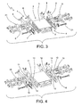
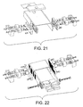
- the reference number 1 globally designates a sliding device 1 for railway switches according to the present invention.
- the sliding device 1 is meant to be coupled to railway switches (not shown) which have at least a fixed stock rail and a least a point movable, on command, between an active position, in which it is close to the stock rail, and an inactive position, in which it is distanced from the stock rail.
- the sliding device 1 shown in the accompanying figures is destined to support the point during its move between the active position and the inactive position and during its permanence in the inactive position, according to the operating procedures described in the patent EP 922 807 .
- the sliding device 1 comprises first of all a support structure 2 which has a central body 3 and two lateral flanks 4 connected to the central body 3.
- the central body 3 can be coupled to an upper portion of a sliding bearing mounted over a sleeper of a track (not shown), and the support structure 2 has a "C" shaped, in order partially to encompass the sliding bearing.
- the central body 3 is constituted by a flat plate which may have laterally (with reference to the direction of development which in use is perpendicular to the track) two flanges 5, perpendicular thereto, extending downwards, for the connection of the lateral flanks 4.
- the sliding device 1 is also provided with at least two rotary sliding elements 6 able to support the point in the inactive position.
- they are idle rollers 6 pivotally engaged to the lateral flanks 4 of the support structure 2, with horizontal axes of rotation, mutually parallel and substantially perpendicular, in use, to the direction of actuation of the point in correspondence with the sliding device 1.
- two, four, six or more rotary sliding elements 6 can be provided, with half associated to a lateral flank 4 and half to the other one.
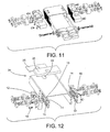
- the lateral flanks 4 have at least a first part 8 associated to the central body 3 and at least a second part 9 associated to the first part 8.
- the first part 8 is fastened to the central body 3, for instance by means of welding, and, in the illustrated embodiments, it vertically extends laterally to the central body 3 itself (in the cases where they are present, it is coupled to the vertical flanges 5 of the central body 3).
- the second part 9 is instead movable relative to the first part 8 in such a way as to be adjustable vertically relative thereto, to adapt the position of the sliding elements 6 to the operative conditions of the switch whereto the sliding device 1 is applied.
- the second movable part 9 of the flanks is removably secured to the first fixed part 8, whereto it is connected by means of one or more fastening screws 10 which are inserted into threaded holes 11 obtained on the fixed part 8 and possibly on the vertical flanges of the central body 3.
- the mobile part 9 has vertically elongated through holes 12 which allow to adjust its position.
- the second mobile part 9 of the flanks can be adjustable relative to the fixed part 8, both in continuous fashion (solution, not shown herein, in which the coupling surfaces are smooth), and in discrete fashion (as shown in the accompanying figures) with the capability to provide adjustment according to a predefined pitch.
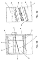
- first part 8 and the second part 9 of the lateral flanks 4 respectively have a first and a second coupling surface 13, 14, at least partly substantially having complementary shapes.
- each coupling surface 13, 14 has a indentations 15 for coupling with the other surface (the indentations 15 are visible only in Figures 25 through 27 , whilst in the other figures it is shown with a black area).
- the pitch of the indentations 15 constitutes the pitch for adjusting the movable part 9.
- the discrete adjustment solution illustrated herein is preferable both when there are requirements for mechanical tightness between the movable part 9 and the fixed part 8, and to facilitate the positioning of the rotary sliding elements 6.
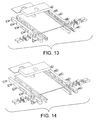
- the movable part 9 or the fixed part 8 of each lateral flank 4 or both have an appendage 16 with mainly horizontal development positioned on the side of the device which in use is oriented towards the track.
- This appendage 16 is able, in use, to be coupled to the lower part of the stock rail, and it inferiorly has a profile 17 for coupling to said stock rail.
- the appendage 16 is provided with means 17 for adjusting the position of the movable part 9 or of the fixed part 8 whereof it is a part, operatively active in correspondence with the coupling profile 17.
- the adjustment means 17 comprise a through screw 18 with mainly vertical development, inserted through the appendage 16 in proximity with its tip.
- means 19 for locking the through screw 18 are provided, for selectively enabling or inhibiting its adjustment.
- the locking means 19 are constituted by a horizontal screw 20 which intercepts each through screw 18.
- each idle roller 6 has a lateral surface 21, hump shaped, to improve the sliding of the point.
- fastening means 7 In regard to the fastening means 7, they can assume the most suitable shape according to requirements.
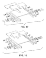
- the fastening means comprise at least a slot 22 obtained in the support structure 2 and at least a locking member 23 inserted through the slot 22.
- This solution allows to adjust the position of the sliding device 1 relative to the bearing and to the point.
- the slot 22 is elongated according to a substantially horizontal direction of development and, in use, transverse to the track, whilst the locking member 23 is able to be hitched in use either with the sliding bearing or with the sleeper.
- the locking member 23 is not shown, but it can be constituted either by a locking screw, or by the mounting screw of the sliding bearing.
- the slot 22 is obtained along the central longitudinal axis of the central body 3, in correspondence with the end 24 which in use is farther away from the track. Moreover, the slot 22 is open in correspondence with said end 24 and two holed metal plates 25 are provided for tightness ( Figure 12 ).
- the first engagement element 27 has a nut screw 29 for receiving the tightening screw 26.
- the first and the second engagement elements 27, 28, which can be inserted into cavities present on the sliding bearing, have respective inclined surfaces 30, relative to said tightening screw 26, which allow their mutual sliding.
- the first engagement element 27 can slide along the tightening screw 26 following its rotation in a direction or in the other.
- screwing the tightening screw 26 causes the movement of the two engagement elements 27, 28 within the cavity (by mutual sliding along the respective inclined surfaces 30), between a first configuration of minimum bulk, in which they can be inserted without interference into the cavity, and a second configuration of maximum bulk, in which they act in sealed fashion within said cavity by means of two corresponding gripping surfaces 31.
- a return spring 32 which tends to keep them in the position of minimum bulk.
- an indented washer 33 which interacts with an additional indented portion 34 of the lateral flank 4 (shown in black colour in the accompanying figures).
- Figures 1 through 24 also show constructive elements (such as washers, split pins, bearings, etc.), not described because they are known, and utilised in the usual fashion for mounting, in particular, the idle rollers 6).
- constructive elements such as washers, split pins, bearings, etc.
- the mounting of the sliding device 1 of the present invention provided with the engagement elements 27, 28, entails, first of all, the preparation of the bearing whereto it is to be applied, which is cleaned and deburred at least on the edges.
- the cavities of the bearing must be completely freed from any deposits which may have accumulated therein.
- the device is also correctly positioned transversely to the track by means of the slots 22.
- the height of the idle rollers 6 must be verified to see whether it is adequate.
- the device is so fitted, once the support structure 2 is positioned and locked, it is also possible to act on the through screws 18 of the adjustment means 17 to bring them to bear on the stock rail. Lastly, they are also locked by means of the horizontal screws 20.
- the mounting is similar, with obvious modifications, in the case of the first type of fastening means 7 described herein.
- the present invention achieves important advantages.
- the sliding device for railway switches of the present invention can be easily mounted with an optimal adjustment on any railway switch, regardless of the relative position of the bearing and of the point.
Landscapes
- Engineering & Computer Science (AREA)
- Mechanical Engineering (AREA)
- Architecture (AREA)
- Civil Engineering (AREA)
- Structural Engineering (AREA)
- Railway Tracks (AREA)
- Train Traffic Observation, Control, And Security (AREA)
- Push-Button Switches (AREA)
- Slide Switches (AREA)
- Switches That Are Operated By Magnetic Or Electric Fields (AREA)
- Electrophonic Musical Instruments (AREA)
- Bearings For Parts Moving Linearly (AREA)
Claims (16)
- Verschiebevorrichtung für Weichenschaltungen mit einer Anschlagschiene und wenigstens eine Weichenzunge, in der Lage, sich auf eine Betätigung hin zwischen einer aktiven Position, in welcher sie dicht an der Anschlagschiene liegt, und einer nicht aktiven Position zu bewegen, in welcher sie von der Anschlagschiene entfernt ist, wobei die genannte Verschiebevorrichtung (1) enthält:- eine Trägerstruktur (2) mit einem mittleren Körper (3), in der Lage, mit einem oberen Abschnitt eines Gleitlagers verbunden zu werden, montiert über einer Schwelle einer Schiene, und zwei Seitenflanken (4), angeschlossen an den genannten mittleren Körper (3);- wenigstens zwei Drehschiebeelemente (6), in der Lage, die genannte Weichenzunge in der genannten nicht aktiven Position zu halten und montiert eins an jeder der genannten Seitenflanken (4); und- Mittel (7) zum Befestigen der genannten Trägerstruktur (2) an dem genannten Gleitlager;dadurch gekennzeichnet, dass die genannten Seitenflanken (4) wenigsten einen ersten Teil (8) enthalten, der an dem mittleren Körper (3) befestigt ist, und wenigstens einen zweiten beweglichen Teil (9), zugeordnet dem ersten Teil (8) und vertikal im Verhältnis zu dem genannten ersten Teil (8) regulierbar, um die Position der Schiebeelemente (6) den Betriebsbedingungen anzupassen.
- Verschiebevorrichtung für Weichenschaltungen nach Patentanspruch 1, dadurch gekennzeichnet, dass der zweite bewegliche Teil (9) der Flanken lösbar an dem ersten feststehenden Teil (8) angebracht ist.
- Verschiebevorrichtung für Weichenschaltungen nach Patentanspruch 2, dadurch gekennzeichnet, dass der genannte bewegliche Teil (9) an den feststehenden Teil (8) mit Hilfe von einer oder mehreren Befestigungsschrauben (10) angeschlossen ist.
- Verschiebevorrichtung für Weichenschaltungen nach Patentanspruch 1, 2 oder 3, dadurch gekennzeichnet, dass der zweite bewegliche Teil (9) der Flanken in kontinuierlicher Weise im Verhältnis zu dem feststehenden Teil (8) regulierbar ist.
- Verschiebevorrichtung für Weichenschaltungen nach Patentanspruch 1, 2 oder 3, dadurch gekennzeichnet, dass der zweite bewegliche Teil (9) der Flanken in diskreter Weise im Verhältnis zu dem feststehenden Teil (8) regulierbar ist.
- Verschiebevorrichtung für Weichenschaltungen nach Patentanspruch 5, dadurch gekennzeichnet, dass der genannte erste Teil (8) und der genannte zweite Teil (9) der Seitenflanken (4) jeweils eine erste und eine zweite Verbindungsfläche (13), (14) aufweisen, wenigstens teilweise einander ergänzend geformt, von welchen jede Einkerbungen (15) zum Verbinden mit dem anderen Teil hat.
- Verschiebevorrichtung für Weichenschaltungen nach einem beliebigen der vorstehenden Patentansprüche, dadurch gekennzeichnet, dass wenigstens der bewegliche Teil (9) und/oder der feststehende Teil (8) von jeder Seitenflanke (4) einen im wesentlichen horizontalen Ansatz (16) aufweist, dazu vorgesehen, sich im Betrieb mit dem unteren Teil der Anschlagschiene zu verbinden, und welcher an der Unterseite ein Profil (17) für den Anschluss an die genannte Anschlagschiene aufweist, und dadurch, dass sie ausserdem Mittel (17) zum Regulieren der Position des genannten beweglichen Teils (9) enthält, zugeordnet dem genannten Ansatz (16) und aktiv an dem genannten Anschlussprofil (17).
- Verschiebevorrichtung für Weichenschaltungen nach Patentanspruch 7, dadurch gekennzeichnet, dass die genannten Reguliermittel (17) eine durchgehende Schraube (18) von vorwiegend vertikaler Ausdehnung enthalten, eingesetzt in den genannten Ansatz (16) und im Betrieb gegen den unteren Teil der Anschlagschiene drückend.
- Verschiebevorrichtung für Weichenschaltungen nach Patentanspruch 8, dadurch gekennzeichnet, dass sie ausserdem Mittel (19) zum Blockieren der genannten durchgehenden Schraube (18) enthält, um wahlweise deren Regulierung zu ermöglichen und zu verhindern.
- Verschiebevorrichtung für Weichenschaltungen nach einem beliebigen der vorstehenden Patentansprüche, dadurch gekennzeichnet, dass sie eine Anzahl von Drehschiebeelementen (6) enthält, die den beweglichen Teilen (9) einer jeden Seitenflanke (4) zugeordnet sind.
- Verschiebevorrichtung für Weichenschaltungen nach einem beliebigen der vorstehenden Patentansprüche, dadurch gekennzeichnet, dass jedes Drehschiebeelement (6) aus einer leerlaufenden Rolle (6) besteht.
- Verschiebevorrichtung für Weichenschaltungen nach Patentanspruch 11, dadurch gekennzeichnet, dass jede leerlaufende Rolle (6) eine buckelförmige seitliche Oberfläche (21) hat.
- Verschiebevorrichtung für Weichenschaltungen nach einem beliebigen der vorstehenden Patentansprüche, dadurch gekennzeichnet, dass die genannten Befestigungsmittel (7) wenigstens einen Schlitz (22) enthalten, erhalten in der Trägerstruktur (2) und länglich nach einer im wesentlichen horizontalen Ausdehnungsrichtung, und wenigstens ein Blockierelement (23), eingesetzt in den genannten Schlitz (22) und in der Lage, im Betrieb an dem genannten Gleitlager oder an der genannten Schwelle gespannt zu werden.
- Verschiebevorrichtung für Weichenschaltungen nach Patentanspruch 13, dadurch gekennzeichnet, dass das genannte Blockierelement (23) eine Blockierschraube enthält, welche an das genannte Gleitlager oder die genannte Schwelle geschraubt werden kann.
- Verschiebevorrichtung für Weichenschaltungen nach Patentanspruch 13, dadurch gekennzeichnet, dass das genannte Blockierelement (23) wenigstens eine Spannschraube (26) enthält, eingesetzt durch den genannten Schlitz (22), ein erstes Eingriffselement (27) mit einer Mutterschraube (29) zur Aufnahme der genannten Spannschraube (26) und ein zweites Eingriffselement (28), wobei die ersten und zweiten Eingriffselemente (27), (28) in einen Hohlraum eingesetzt werden können, der an dem genannten Gleitlager vorhanden ist und jeweilige schräge Oberflächen (30) aufweisen, im Verhältnis zu der genannten Spannschraube (26), verbunden zum gegenseitigen Gleiten einer an der anderen, wobei das Eindrehen der Spannschraube (26) das Verschieben der beiden Eingriffselemente (27), (28) im Inneren des Hohlraums durch gegenseitiges Gleiten entlang der jeweiligen schrägen Oberflächen (30) bewirkt, und zwar zwischen einer ersten Konfiguration des minimalen Umfangs, in welcher sie ohne Behinderung in das Innere des Hohlraums eingesetzt werden können, und einer zweiten Konfiguration des maximalen Umfangs, in welcher sie in abdichtender Weise und mit Hilfe der beiden entsprechenden griffigen Oberflächen (31) im Inneren des Hohlraums wirken.
- Verschiebevorrichtung für Weichenschaltungen nach Patentanspruch 15, dadurch gekennzeichnet, dass sie zwei der Schlitze (22) enthält, jeder zugeordnet einer jeden Seitenflanke (4), und zwei der genannten Blockierelemente (23), in der Lage, in die beiden Vertiefungen eingesetzt zu werden, die seitlich an dem genannten Lager erhalten sind.
Applications Claiming Priority (1)
| Application Number | Priority Date | Filing Date | Title |
|---|---|---|---|
| PCT/IT2003/000863 WO2005064080A1 (en) | 2003-12-30 | 2003-12-30 | A sliding device for railway switches |
Publications (2)
| Publication Number | Publication Date |
|---|---|
| EP1706539A1 EP1706539A1 (de) | 2006-10-04 |
| EP1706539B1 true EP1706539B1 (de) | 2008-05-07 |
Family
ID=34717602
Family Applications (1)
| Application Number | Title | Priority Date | Filing Date |
|---|---|---|---|
| EP03819229A Expired - Lifetime EP1706539B1 (de) | 2003-12-30 | 2003-12-30 | Weichenschalter |
Country Status (8)
| Country | Link |
|---|---|
| US (1) | US20070176055A1 (de) |
| EP (1) | EP1706539B1 (de) |
| AT (1) | ATE394548T1 (de) |
| AU (1) | AU2003300752A1 (de) |
| CA (1) | CA2552373A1 (de) |
| DE (1) | DE60320871D1 (de) |
| ES (1) | ES2305584T3 (de) |
| WO (1) | WO2005064080A1 (de) |
Family Cites Families (9)
| Publication number | Priority date | Publication date | Assignee | Title |
|---|---|---|---|---|
| CH368201A (de) | 1959-02-27 | 1963-03-31 | Peddinghaus Carl Dan Kg | Federnde Rollenlagerung für Weichenzungen |
| DE1658366A1 (de) | 1967-10-16 | 1970-10-22 | Wolfen Filmfab Veb | Weichenzungenleitvorrichtung |
| LU75283A1 (de) * | 1976-07-01 | 1978-02-08 | ||
| AT375697B (de) | 1982-09-03 | 1984-08-27 | Maurer Gerhard | Rollenlagerung fuer weichenzungen |
| DE4041264A1 (de) | 1990-12-21 | 1992-06-25 | Peddinghaus Carl Dan Gmbh | Vorrichtung zum anheben der zungenschiene einer weiche |
| US5390881A (en) | 1992-07-22 | 1995-02-21 | Bwg Butzbacher Weichenbau Gmbh | Roller assembly for a switch tongue used with a stock rail |
| DE9317723U1 (de) | 1993-11-19 | 1994-01-20 | Enzesfeld-Caro Metallwerke Ag, Enzesfeld | Weiche für Gleise des schienengebundenen Verkehrs |
| US5501418A (en) * | 1994-10-03 | 1996-03-26 | Humphrey; John | Switch point roller assist apparatus |
| IT1298067B1 (it) | 1997-12-10 | 1999-12-20 | Impresa Angelo Mazzi Snc Di Ma | Dispositivo di scorrimento per scambi ferroviari |
-
2003
- 2003-12-30 AT AT03819229T patent/ATE394548T1/de active
- 2003-12-30 WO PCT/IT2003/000863 patent/WO2005064080A1/en not_active Ceased
- 2003-12-30 AU AU2003300752A patent/AU2003300752A1/en not_active Abandoned
- 2003-12-30 EP EP03819229A patent/EP1706539B1/de not_active Expired - Lifetime
- 2003-12-30 DE DE60320871T patent/DE60320871D1/de not_active Expired - Lifetime
- 2003-12-30 CA CA002552373A patent/CA2552373A1/en not_active Abandoned
- 2003-12-30 ES ES03819229T patent/ES2305584T3/es not_active Expired - Lifetime
- 2003-12-30 US US10/585,105 patent/US20070176055A1/en not_active Abandoned
Also Published As
| Publication number | Publication date |
|---|---|
| AU2003300752A1 (en) | 2005-07-21 |
| WO2005064080A1 (en) | 2005-07-14 |
| ATE394548T1 (de) | 2008-05-15 |
| CA2552373A1 (en) | 2005-07-14 |
| ES2305584T3 (es) | 2008-11-01 |
| US20070176055A1 (en) | 2007-08-02 |
| DE60320871D1 (de) | 2008-06-19 |
| EP1706539A1 (de) | 2006-10-04 |
Similar Documents
| Publication | Publication Date | Title |
|---|---|---|
| CN104264537B (zh) | D型便梁可调式定位扣件支架 | |
| CN101429745B (zh) | 用于装配和拆卸紧固装置的装置 | |
| EP1706539B1 (de) | Weichenschalter | |
| CA2482456C (en) | Drop down lug for railroad switch application | |
| US9309629B2 (en) | Roller assembly for a railway switch | |
| AU2844101A (en) | Rail switch lock for points tongues | |
| CN107684259A (zh) | 抽屉面板的连接调节装置及抽屉 | |
| EP0922807B1 (de) | Gleitvorrichtung für Eisenbahnweichen | |
| KR20120066440A (ko) | 철도 분기기용 무도유 롤러 베이스 어셈블리 | |
| AU2018202495A1 (en) | Bracket for fastening of supply lines or the like to a wall | |
| CN2616626Y (zh) | 拉力锁 | |
| CN1307358C (zh) | 铰链 | |
| CN219951568U (zh) | 一种可调节铁路轨撑 | |
| CN222291396U (zh) | 一种便于调整偏距的车轮组件调位器 | |
| CN221790737U (zh) | 一种便于更换的冲孔冲头及冲压设备 | |
| KR102491155B1 (ko) | 철도 신호 케이블 보호장치 | |
| WO2013049017A1 (en) | Height adjustment device for transit shaft and arm assembly | |
| KR200187609Y1 (ko) | 현가식 도어용 이동롤러의 고정 브라켓 | |
| CN217420846U (zh) | 一种便于拆装的风撑 | |
| CN216640322U (zh) | 一种声屏障快速固定装置 | |
| CN220456264U (zh) | 一种与墙体齐平的开关装置 | |
| CN207739863U (zh) | 一种轨道交通站台门滑动门三维调节装置 | |
| CN113349561B (zh) | 一种衣柜 | |
| CN105417299A (zh) | 一种整体式电梯操纵箱 | |
| CN102277803B (zh) | 螺杆式道岔用顶铁 |
Legal Events
| Date | Code | Title | Description |
|---|---|---|---|
| PUAI | Public reference made under article 153(3) epc to a published international application that has entered the european phase |
Free format text: ORIGINAL CODE: 0009012 |
|
| 17P | Request for examination filed |
Effective date: 20060628 |
|
| AK | Designated contracting states |
Kind code of ref document: A1 Designated state(s): AT BE BG CH CY CZ DE DK EE ES FI FR GB GR HU IE IT LI LU MC NL PT RO SE SI SK TR |
|
| DAX | Request for extension of the european patent (deleted) | ||
| GRAP | Despatch of communication of intention to grant a patent |
Free format text: ORIGINAL CODE: EPIDOSNIGR1 |
|
| GRAS | Grant fee paid |
Free format text: ORIGINAL CODE: EPIDOSNIGR3 |
|
| GRAA | (expected) grant |
Free format text: ORIGINAL CODE: 0009210 |
|
| AK | Designated contracting states |
Kind code of ref document: B1 Designated state(s): AT BE BG CH CY CZ DE DK EE ES FI FR GB GR HU IE IT LI LU MC NL PT RO SE SI SK TR |
|
| REG | Reference to a national code |
Ref country code: GB Ref legal event code: FG4D |
|
| REG | Reference to a national code |
Ref country code: CH Ref legal event code: EP |
|
| REG | Reference to a national code |
Ref country code: IE Ref legal event code: FG4D Free format text: LANGUAGE OF EP DOCUMENT: FRENCH |
|
| REF | Corresponds to: |
Ref document number: 60320871 Country of ref document: DE Date of ref document: 20080619 Kind code of ref document: P |
|
| PG25 | Lapsed in a contracting state [announced via postgrant information from national office to epo] |
Ref country code: SI Free format text: LAPSE BECAUSE OF FAILURE TO SUBMIT A TRANSLATION OF THE DESCRIPTION OR TO PAY THE FEE WITHIN THE PRESCRIBED TIME-LIMIT Effective date: 20080507 |
|
| PG25 | Lapsed in a contracting state [announced via postgrant information from national office to epo] |
Ref country code: FI Free format text: LAPSE BECAUSE OF FAILURE TO SUBMIT A TRANSLATION OF THE DESCRIPTION OR TO PAY THE FEE WITHIN THE PRESCRIBED TIME-LIMIT Effective date: 20080507 Ref country code: NL Free format text: LAPSE BECAUSE OF FAILURE TO SUBMIT A TRANSLATION OF THE DESCRIPTION OR TO PAY THE FEE WITHIN THE PRESCRIBED TIME-LIMIT Effective date: 20080507 |
|
| REG | Reference to a national code |
Ref country code: ES Ref legal event code: FG2A Ref document number: 2305584 Country of ref document: ES Kind code of ref document: T3 |
|
| NLV1 | Nl: lapsed or annulled due to failure to fulfill the requirements of art. 29p and 29m of the patents act | ||
| PG25 | Lapsed in a contracting state [announced via postgrant information from national office to epo] |
Ref country code: DK Free format text: LAPSE BECAUSE OF FAILURE TO SUBMIT A TRANSLATION OF THE DESCRIPTION OR TO PAY THE FEE WITHIN THE PRESCRIBED TIME-LIMIT Effective date: 20080507 Ref country code: SE Free format text: LAPSE BECAUSE OF FAILURE TO SUBMIT A TRANSLATION OF THE DESCRIPTION OR TO PAY THE FEE WITHIN THE PRESCRIBED TIME-LIMIT Effective date: 20080807 Ref country code: CZ Free format text: LAPSE BECAUSE OF FAILURE TO SUBMIT A TRANSLATION OF THE DESCRIPTION OR TO PAY THE FEE WITHIN THE PRESCRIBED TIME-LIMIT Effective date: 20080507 Ref country code: PT Free format text: LAPSE BECAUSE OF FAILURE TO SUBMIT A TRANSLATION OF THE DESCRIPTION OR TO PAY THE FEE WITHIN THE PRESCRIBED TIME-LIMIT Effective date: 20081007 |
|
| PG25 | Lapsed in a contracting state [announced via postgrant information from national office to epo] |
Ref country code: RO Free format text: LAPSE BECAUSE OF FAILURE TO SUBMIT A TRANSLATION OF THE DESCRIPTION OR TO PAY THE FEE WITHIN THE PRESCRIBED TIME-LIMIT Effective date: 20080507 Ref country code: BE Free format text: LAPSE BECAUSE OF FAILURE TO SUBMIT A TRANSLATION OF THE DESCRIPTION OR TO PAY THE FEE WITHIN THE PRESCRIBED TIME-LIMIT Effective date: 20080507 Ref country code: SK Free format text: LAPSE BECAUSE OF FAILURE TO SUBMIT A TRANSLATION OF THE DESCRIPTION OR TO PAY THE FEE WITHIN THE PRESCRIBED TIME-LIMIT Effective date: 20080507 |
|
| PLBE | No opposition filed within time limit |
Free format text: ORIGINAL CODE: 0009261 |
|
| STAA | Information on the status of an ep patent application or granted ep patent |
Free format text: STATUS: NO OPPOSITION FILED WITHIN TIME LIMIT |
|
| 26N | No opposition filed |
Effective date: 20090210 |
|
| PG25 | Lapsed in a contracting state [announced via postgrant information from national office to epo] |
Ref country code: EE Free format text: LAPSE BECAUSE OF FAILURE TO SUBMIT A TRANSLATION OF THE DESCRIPTION OR TO PAY THE FEE WITHIN THE PRESCRIBED TIME-LIMIT Effective date: 20080507 Ref country code: BG Free format text: LAPSE BECAUSE OF FAILURE TO SUBMIT A TRANSLATION OF THE DESCRIPTION OR TO PAY THE FEE WITHIN THE PRESCRIBED TIME-LIMIT Effective date: 20080807 |
|
| PG25 | Lapsed in a contracting state [announced via postgrant information from national office to epo] |
Ref country code: MC Free format text: LAPSE BECAUSE OF NON-PAYMENT OF DUE FEES Effective date: 20081231 |
|
| REG | Reference to a national code |
Ref country code: CH Ref legal event code: PL |
|
| REG | Reference to a national code |
Ref country code: IE Ref legal event code: MM4A |
|
| PG25 | Lapsed in a contracting state [announced via postgrant information from national office to epo] |
Ref country code: LI Free format text: LAPSE BECAUSE OF NON-PAYMENT OF DUE FEES Effective date: 20081231 Ref country code: CH Free format text: LAPSE BECAUSE OF NON-PAYMENT OF DUE FEES Effective date: 20081231 |
|
| PG25 | Lapsed in a contracting state [announced via postgrant information from national office to epo] |
Ref country code: IE Free format text: LAPSE BECAUSE OF NON-PAYMENT OF DUE FEES Effective date: 20081230 |
|
| PG25 | Lapsed in a contracting state [announced via postgrant information from national office to epo] |
Ref country code: LU Free format text: LAPSE BECAUSE OF NON-PAYMENT OF DUE FEES Effective date: 20081230 Ref country code: HU Free format text: LAPSE BECAUSE OF FAILURE TO SUBMIT A TRANSLATION OF THE DESCRIPTION OR TO PAY THE FEE WITHIN THE PRESCRIBED TIME-LIMIT Effective date: 20081108 Ref country code: CY Free format text: LAPSE BECAUSE OF FAILURE TO SUBMIT A TRANSLATION OF THE DESCRIPTION OR TO PAY THE FEE WITHIN THE PRESCRIBED TIME-LIMIT Effective date: 20080507 |
|
| PG25 | Lapsed in a contracting state [announced via postgrant information from national office to epo] |
Ref country code: TR Free format text: LAPSE BECAUSE OF FAILURE TO SUBMIT A TRANSLATION OF THE DESCRIPTION OR TO PAY THE FEE WITHIN THE PRESCRIBED TIME-LIMIT Effective date: 20080507 |
|
| PG25 | Lapsed in a contracting state [announced via postgrant information from national office to epo] |
Ref country code: GR Free format text: LAPSE BECAUSE OF FAILURE TO SUBMIT A TRANSLATION OF THE DESCRIPTION OR TO PAY THE FEE WITHIN THE PRESCRIBED TIME-LIMIT Effective date: 20080808 |
|
| REG | Reference to a national code |
Ref country code: FR Ref legal event code: PLFP Year of fee payment: 13 |
|
| REG | Reference to a national code |
Ref country code: FR Ref legal event code: PLFP Year of fee payment: 14 |
|
| PGFP | Annual fee paid to national office [announced via postgrant information from national office to epo] |
Ref country code: FR Payment date: 20161221 Year of fee payment: 14 Ref country code: AT Payment date: 20161216 Year of fee payment: 14 |
|
| PGFP | Annual fee paid to national office [announced via postgrant information from national office to epo] |
Ref country code: DE Payment date: 20170111 Year of fee payment: 14 |
|
| REG | Reference to a national code |
Ref country code: DE Ref legal event code: R119 Ref document number: 60320871 Country of ref document: DE |
|
| REG | Reference to a national code |
Ref country code: AT Ref legal event code: MM01 Ref document number: 394548 Country of ref document: AT Kind code of ref document: T Effective date: 20171230 |
|
| REG | Reference to a national code |
Ref country code: FR Ref legal event code: ST Effective date: 20180831 |
|
| PG25 | Lapsed in a contracting state [announced via postgrant information from national office to epo] |
Ref country code: FR Free format text: LAPSE BECAUSE OF NON-PAYMENT OF DUE FEES Effective date: 20180102 Ref country code: DE Free format text: LAPSE BECAUSE OF NON-PAYMENT OF DUE FEES Effective date: 20180703 |
|
| PG25 | Lapsed in a contracting state [announced via postgrant information from national office to epo] |
Ref country code: AT Free format text: LAPSE BECAUSE OF NON-PAYMENT OF DUE FEES Effective date: 20171230 |
|
| PGFP | Annual fee paid to national office [announced via postgrant information from national office to epo] |
Ref country code: GB Payment date: 20191226 Year of fee payment: 17 |
|
| GBPC | Gb: european patent ceased through non-payment of renewal fee |
Effective date: 20201230 |
|
| PG25 | Lapsed in a contracting state [announced via postgrant information from national office to epo] |
Ref country code: GB Free format text: LAPSE BECAUSE OF NON-PAYMENT OF DUE FEES Effective date: 20201230 |
|
| PGFP | Annual fee paid to national office [announced via postgrant information from national office to epo] |
Ref country code: ES Payment date: 20220110 Year of fee payment: 19 |
|
| PGFP | Annual fee paid to national office [announced via postgrant information from national office to epo] |
Ref country code: IT Payment date: 20221222 Year of fee payment: 20 |
|
| P01 | Opt-out of the competence of the unified patent court (upc) registered |
Effective date: 20230404 |
|
| REG | Reference to a national code |
Ref country code: ES Ref legal event code: FD2A Effective date: 20240131 |
|
| PG25 | Lapsed in a contracting state [announced via postgrant information from national office to epo] |
Ref country code: ES Free format text: LAPSE BECAUSE OF NON-PAYMENT OF DUE FEES Effective date: 20221231 |
|
| PG25 | Lapsed in a contracting state [announced via postgrant information from national office to epo] |
Ref country code: ES Free format text: LAPSE BECAUSE OF NON-PAYMENT OF DUE FEES Effective date: 20221231 |