EP1705604B1 - Multilevel demodulation method and device - Google Patents
Multilevel demodulation method and device Download PDFInfo
- Publication number
- EP1705604B1 EP1705604B1 EP06111387A EP06111387A EP1705604B1 EP 1705604 B1 EP1705604 B1 EP 1705604B1 EP 06111387 A EP06111387 A EP 06111387A EP 06111387 A EP06111387 A EP 06111387A EP 1705604 B1 EP1705604 B1 EP 1705604B1
- Authority
- EP
- European Patent Office
- Prior art keywords
- level
- modulation
- transponder
- threshold
- voltage
- Prior art date
- Legal status (The legal status is an assumption and is not a legal conclusion. Google has not performed a legal analysis and makes no representation as to the accuracy of the status listed.)
- Not-in-force
Links
Images


Classifications
-
- G—PHYSICS
- G06—COMPUTING; CALCULATING OR COUNTING
- G06K—GRAPHICAL DATA READING; PRESENTATION OF DATA; RECORD CARRIERS; HANDLING RECORD CARRIERS
- G06K19/00—Record carriers for use with machines and with at least a part designed to carry digital markings
- G06K19/06—Record carriers for use with machines and with at least a part designed to carry digital markings characterised by the kind of the digital marking, e.g. shape, nature, code
- G06K19/067—Record carriers with conductive marks, printed circuits or semiconductor circuit elements, e.g. credit or identity cards also with resonating or responding marks without active components
- G06K19/07—Record carriers with conductive marks, printed circuits or semiconductor circuit elements, e.g. credit or identity cards also with resonating or responding marks without active components with integrated circuit chips
- G06K19/0723—Record carriers with conductive marks, printed circuits or semiconductor circuit elements, e.g. credit or identity cards also with resonating or responding marks without active components with integrated circuit chips the record carrier comprising an arrangement for non-contact communication, e.g. wireless communication circuits on transponder cards, non-contact smart cards or RFIDs
Definitions
- the invention relates to information exchange techniques between a fixed station (reader) and a contactless transponder (card, tag) placed in the electromagnetic field emitted by the reader.
- the invention relates to a method of demodulation in the transponder of the modulation transmitted by the reader.
- a reader 2 emits a radio frequency magnetic field, this field is used on the one hand by a transponder 4 to create its supply voltage and on the other hand to exchange information.
- the reader 2 sends its information by amplitude modulating this magnetic field (Amplitude Shift Keying or ASK).
- the Figure 1B represents the field emitted by a fixed station as a function of the value of the bit it wishes to transmit.
- the sign signal S (V c ) is the signal used to retrieve the information transmitted by the fixed station 2.
- the direction of variation of the servocontrol voltage of an analog / digital converter (demodulator of transponder 4) is used to determine the level of the modulation.
- the length of the identical bit sequences S (V c ) is compared with thresholds, which makes it possible to obtain the information relating to the value of the difference between the current modulation level and the previous level.
- the signal-to-noise ratio is too high and the transponders can only be read in a very small field area.
- Patent Abstracts of Japan, published under No. 07123121 May 12, 1995 discloses a demodulation system.
- the document FR 2,853,479 discloses an inductively coupled multi-level modulation teletransmission device.
- the invention proposes a method for demodulating a signal modulated in amplitude by a reader and sent to a transponder, in the case where the number of levels N is greater than or equal to 2.
- the invention firstly relates to a method for demodulating information transmitted by amplitude modulation by a reader to a transponder, according to claim 1.
- a threshold reference table for example a reference table of a comparator, not theoretical values of these thresholds, but values adapted to the device used. and to correct the nonlinearities due to the differences of jump from one level to another.
- thresholds can be established; For example, a signal with all possible jumps is sent, the transponder measures the corresponding values, and a bijection can be established between the set of real jumps, for all the levels, and all the values of the thresholds, which will be stored. in the reference table.
- thresholds For example for 4 levels, there are 6 possible thresholds (-3, -2, -1, +1, +2, +3). Theoretically, all these thresholds are identical for each level. But the reality is quite different: for reasons of non-linearity of the system, the thresholds vary from one level to another; in other words, the +1 displacement from a first level, for example the level 2, does not necessarily have the same amplitude as the +1 displacement from a second level, for example the level 0. It results from errors during demodulation.
- the table will then no longer include 6 thresholds but 24 values (6 values per level).
- the invention therefore also relates to a method for demodulating information transmitted by amplitude modulation by a reader to a reader.
- transponder for example a card or an RFID tag, comprising a step of comparing, at threshold values, variations of a servocontrol voltage of a demodulator and comprising a preliminary step of physically measuring the value of these thresholds.
- the invention also relates to a device for demodulating information transmitted by amplitude modulation by a reader to a transponder, such as an RFID tag, according to claim 4.
- It may further comprise antenna means, load impedance means at the terminals of the antenna, and loop control means of a voltage across the load impedance.
- the regulating means may, according to one embodiment, include means for rectifying the voltage at the terminals of the antenna, and control means for modifying the impedance as a function of the output of the rectifying means.
- Demodulation means may include analog-to-digital conversion means between the control means and the rectifying means.
- any displacement or possible jump from each modulation level is previously listed and stored, for example by means of a so-called preamble signal (an example of which is given later in connection with FIG. figure 6 ) and which contains all the possible jumps from each modulation level.
- the largest (respectively the smallest) allowed jump value is assigned.
- a method according to the invention can be implemented in a transponder in a digital manner, for example by means of a filter, the output of the filter being sent to a device such as for example that illustrated in FIG. Figure 5B .
- the Figure 5A represents a part of the transponder device 4, comprising reception antenna means 10, rectifying circuit means 12, analog-to-digital converter means 16, and control means 14.
- a digital processing circuit 18 provides digital signals representative of the transmitted data.
- the n-bit converter 16 is located in the regulation loop between the rectifying means 12 and the control means 14.
- the oversampling frequency is for example determined by a clock circuit providing clock signals C k to a clock input of the converter 16.
- the oversampling frequency may advantageously be between 10 and 20 MHz.
- the output of the converter 16, connected to the control circuit 14, is therefore connected to the input of a digital processing circuit 18 intended to provide, on N bits, the demodulated data.
- the operation of the demodulation circuit of the portable object of the Figure 5A is illustrated by the signals shown on the Figures 2A and 2B , in the case where the analog-digital converter 16, low resolution, included in the control loop of the AC voltage Vac across the antenna 10, is constituted by a simple comparator providing a sequence of bits at the frequency of on -échantillonage.
- the control circuit 14 includes an integrator supplying an analog voltage signal Vc representative of the n-bit output signals of the converter 16.
- this signal has the form of a rising voltage ramp when the output of the means 16 is at 1 and a downward voltage ramp when this output is at zero.
- the control voltage V c obtained at the output of the control means 14, is never static.
- the control voltage Vc has the form of a sawtooth signal around a mean level (see FIG. Figure 2B ) proportional to the level of the electromotive force, that is to say proportional to the level of the magnetic field emitted by the fixed station 2 and, therefore, representative of the data transmitted by this fixed station 2.
- the magnetic field H varies between times t 0 and t 5
- the level change of the amplitude of this field H causes a change of level of the electromotive force and, consequently, a rapid variation (decreasing at the instant t 1 and increasing at times t 2 , t 3 and t 4 ) of the AC voltage V ac generated across the antenna 10 and the load impedance 11.
- a decrease in the level of the magnetic field H causes the emission of a sequence of consecutive zeros longer than during the servo-control, causing a decrease in the average amplitude of the control voltage V c .
- an increase in the level of the emitted magnetic field results in the emission of a consecutive sequence of "1", which is longer than during servo-control, causing an increase in the average amplitude of the control voltage.
- V c The number of consecutive O or 1 increases with the amplitude of the jump of the electromotive force.
- the digital output signals of the converter 16 therefore contain information representative of the sign and the amplitude of the variation of the level of the emf generated by the field H, ie information representative of the derivative of the envelope of the electromotive force. or the magnetic field.
- the digital processing circuit 18 therefore comprises at least one digital integration function.
- the integration functions of the circuit of control 14 and / or the digital processing circuit 18 may be implemented by means of integrators and / or low-pass filters.
- the regulation loop of the Figure 5A simultaneously provides part of the analog conversion, which makes the whole more compact.
- the effect of possible slow variations in the mean magnetic field level, due to a movement of the portable object 1 is attenuated by the fact that the output information of the converter 16 is representative of the derivative of the envelope of the magnetic field. Slow variations in the average field level are therefore treated as noise and do not disturb the demodulation.
- the Figure 5B gives an exemplary embodiment of a device according to the invention, for a multi-level demodulation exploiting the calculation of the displacement thresholds for each level.
- Such a device comprises means 50 comparators, for comparing the output of the filter 40 (which is located at the input of the block 18 of digital processing, Figure 5B ) with threshold values from a threshold table 80.
- This threshold table is for example fed during a phase or preamble which includes all the possible displacements, as illustrated on the figure 6 . To all these possible displacements is associated all the corrected or authorized displacements.
- the means 60 are adding means, while the reference 70 designates a register.
- the working frequency is the symbol frequency.
- the threshold table 80 is addressed by the value of the modulation level during the time t n . This value therefore gives the level of modulation that was previously calculated for the moment t n .
- the output of the filter 40 is compared with the thresholds contained in the table 80, and the output of the comparator 50 gives the jump dep (t n + 1 ) according to the logic described above. This jump is added at level level (t n ) to give the level received at time t n + 1 .
- the output of the filter Fir is compared to the thresholds. We then obtain the jumps Dep from which we deduce the level of modulation Niv.
- This example concerns a modulation with 4 levels, noted from 0 to 3, and represented schematically on the Figures 8 and 9 .
- the thresholds for each level are not identical, nor necessarily linearly distributed, and the converter in the transponder is not perfectly linear.
- a transaction between the reader 2 and the transponder 4 then begins, for example, with a preamble, defined in such a way that it contains all the existing relative jumps for all the possible levels.
- the transponder will be able to define all the actual jump thresholds.
- the figure 6 gives an example of a preamble, for the case of 4 levels, issued by the reader 2 before a transaction, making it possible to identify for each level its own thresholds of real jumps.
- Table I indicates, for each T i, the threshold (s) calculated for level (n). ⁇ u> Table I ⁇ / u> Ti Threshold (s) Level (n) T1 -1 3 T2 -1 2 T3 -1 1 T4 +1 0 T5 +1 1 T6 +1 2 T7 -2 3 T8 2 1 T9 -3 3 T10 2 0 T11 -2 2 T12 3 0
- Threshold (T i ) represents the threshold calculated or authorized at time T i (see Table I and figure 7 ).
- the thresholds at -256 are prohibited and are assigned the minimum level (respectively maximum).
- the proposed digital demodulation makes it possible to effectively use the output of a sigma delta converter 20, positioned as illustrated on FIG. Figure 5A (between the input of the converter 16 and an input of the digital processing circuit 18).
- This converter makes it possible to increase the resolution of the demodulation by decreasing the influence of the quantization noise generated by the converter 16.
- the management of different thresholds by level and management (or correction) of the prohibited jumps significantly improve the signal-to-noise ratio and increase the quality of the signal. demodulation.
- a system according to the invention has been realized, with a symbol duration of 1.18 ⁇ s, 4 levels per symbol (ie 2 bits per symbol). Such a system has made it possible to transmit data at 1.7 Mbps.
Landscapes
- Engineering & Computer Science (AREA)
- Computer Networks & Wireless Communication (AREA)
- Computer Hardware Design (AREA)
- Microelectronics & Electronic Packaging (AREA)
- Physics & Mathematics (AREA)
- General Physics & Mathematics (AREA)
- Theoretical Computer Science (AREA)
- Digital Transmission Methods That Use Modulated Carrier Waves (AREA)
- Radar Systems Or Details Thereof (AREA)
- Burglar Alarm Systems (AREA)
- Input Circuits Of Receivers And Coupling Of Receivers And Audio Equipment (AREA)
- Near-Field Transmission Systems (AREA)
Abstract
Description
L'invention concerne les techniques d'échanges d'informations entre une station fixe (lecteur) et un transpondeur sans contact (carte, étiquette) placé dans le champ électromagnétique émis par le lecteur.The invention relates to information exchange techniques between a fixed station (reader) and a contactless transponder (card, tag) placed in the electromagnetic field emitted by the reader.
Plus précisément, l'invention concerne une méthode de démodulation dans le transpondeur de la modulation émise par le lecteur.More specifically, the invention relates to a method of demodulation in the transponder of the modulation transmitted by the reader.
Comme illustré sur la
La
Pour augmenter le débit d'informations échangées entre la station fixe 2 et le transpondeur 4, on peut soit augmenter la fréquence du signal modulant soit augmenter le nombre de niveaux d'amplitude de modulation.To increase the information rate exchanged between the
Dans la demande de brevet n°
Les
- H représente le champ modulé par le lecteur (
figure 2A ), - Vc est la tension de commande fournie par l'intégrateur du transpondeur 4 (
figure 2B ), l'amplitude de cette tension est représentative du niveau de l'amplitude du champ magnétique H, et donc des données à transmettre ; - S(Vc) est le signe de la variation de la tension de commande Vc d'une boucle de régulation du transpondeur (
figure 2C ).
- H represents the field modulated by the reader (
Figure 2A ) - V c is the control voltage supplied by the transponder integrator 4 (
Figure 2B ), the amplitude of this voltage is representative of the level of the amplitude of the magnetic field H, and therefore the data to be transmitted; - S (V c ) is the sign of the variation of the control voltage V c of a transponder control loop (
Figure 2C ).
Le signal signe S(Vc) est le signal exploité pour retrouver l'information émise par la station fixe 2.The sign signal S (V c ) is the signal used to retrieve the information transmitted by the
Dans cette méthode on utilise le sens de variation de la tension d'asservissement d'un convertisseur analogique/digital (démodulateur du transpondeur 4) pour connaître le niveau de la modulation.In this method, the direction of variation of the servocontrol voltage of an analog / digital converter (demodulator of transponder 4) is used to determine the level of the modulation.
La longueur des séquences de bits S(Vc) identiques est comparée à des seuils ce qui permet d'obtenir l'information relative à la valeur de la différence entre le niveau de modulation actuel et le niveau précédent.The length of the identical bit sequences S (V c ) is compared with thresholds, which makes it possible to obtain the information relating to the value of the difference between the current modulation level and the previous level.
Dans cette méthode, le rapport signal à bruit est trop élevé et la lecture des transpondeurs ne peut se faire que dans une zone de champ très réduite.In this method, the signal-to-noise ratio is too high and the transponders can only be read in a very small field area.
Il se pose donc le problème de trouver un nouveau dispositif et un nouveau procédé permettant de résoudre ces problèmes de sensibilité et de portée.There is therefore the problem of finding a new device and a new method to solve these problems of sensitivity and scope.
Le document Patent Abstracts of Japan, publié sous le n° 07123121 le 12 mai 1995 décrit un système de démodulation.Patent Abstracts of Japan, published under No. 07123121 May 12, 1995 discloses a demodulation system.
Le document
L'invention propose une méthode pour démoduler un signal modulé en amplitude par un lecteur et envoyé vers un transpondeur, dans le cas où le nombre de niveaux N est supérieur ou égal à 2.The invention proposes a method for demodulating a signal modulated in amplitude by a reader and sent to a transponder, in the case where the number of levels N is greater than or equal to 2.
L'invention concerne d'abord un procédé de démodulation d'une information émise par modulation d'amplitude par un lecteur vers un transpondeur, selon la revendication 1.The invention firstly relates to a method for demodulating information transmitted by amplitude modulation by a reader to a transponder, according to
Selon l'invention, on peut mémoriser dans des moyens de mémorisation, ou dans une table de référence de seuil, par exemple une table de référence d'un comparateur, non pas des valeurs théoriques de ces seuils, mais des valeurs adaptées au dispositif utilisé et permettant de corriger les non linéarités dues aux différences de saut d'un niveau à l'autre.According to the invention, it is possible to memorize, in storage means, or in a threshold reference table, for example a reference table of a comparator, not theoretical values of these thresholds, but values adapted to the device used. and to correct the nonlinearities due to the differences of jump from one level to another.
Il est possible, avant chaque envoi de signal du lecteur au transpondeur, d'envoyer un préambule contenant tous les sauts possibles pour tous les niveaux de modulation afin d'établir les valeurs des seuils.It is possible, before each sending of the signal from the reader to the transponder, to send a preamble containing all the possible jumps for all the modulation levels in order to establish the values of the thresholds.
Au cours d'une étape antérieure, on peut établir les seuils ; on envoie par exemple un signal comportant tous les sauts possibles, le transpondeur mesure les valeurs correspondantes, et on peut établir une bijection entre l'ensemble des sauts réels, pour tous les niveaux, et l'ensemble des valeurs des seuils, qui seront stockées dans la table de référence.In a previous step, thresholds can be established; For example, a signal with all possible jumps is sent, the transponder measures the corresponding values, and a bijection can be established between the set of real jumps, for all the levels, and all the values of the thresholds, which will be stored. in the reference table.
Par exemple pour 4 niveaux, il y a 6 seuils possibles (-3, -2, -1, +1, +2, +3). Théoriquement, tous ces seuils sont identiques pour chaque niveau. Or la réalité est toute autre : pour des raisons de non linéarité du système, les seuils varient d'un niveau à l'autre ; autrement dit, le déplacement +1 à partir d'un premier niveau, par exemple le niveau 2, n'a pas nécessairement la même amplitude que le déplacement +1 à partir d'un deuxième niveau, par exemple le niveau 0. Il en résulte des erreurs lors de la démodulation.For example for 4 levels, there are 6 possible thresholds (-3, -2, -1, +1, +2, +3). Theoretically, all these thresholds are identical for each level. But the reality is quite different: for reasons of non-linearity of the system, the thresholds vary from one level to another; in other words, the +1 displacement from a first level, for example the
On cherche donc à connaître les valeurs réelles de tous les sauts possibles pour déterminer les seuils réels.We therefore seek to know the real values of all the possible jumps to determine the real thresholds.
Par exemple dans le cas de 4 niveaux, la table ne comprendra alors plus 6 seuils mais 24 valeurs (6 valeurs par niveau).For example, in the case of 4 levels, the table will then no longer include 6 thresholds but 24 values (6 values per level).
De plus, tous les déplacements ne sont pas permis. Par exemple, toujours pour 4 niveaux, si le symbole précédent est le niveau 1, seuls sont permis les déplacements -1, +1, +2. Il y aura donc dans la table de référence des valeurs interdites.In addition, not all trips are allowed. For example, always for 4 levels, if the previous symbol is
L'invention concerne donc également un procédé de démodulation d'une information émise par modulation d'amplitude par un lecteur vers un transpondeur, par exemple une carte ou une étiquette RFID, comportant une étape de comparaison, à des valeurs seuil, des variations d'une tension d'asservissement d'un démodulateur et comportant une étape préalable de mesure physique de la valeur de ces seuils.The invention therefore also relates to a method for demodulating information transmitted by amplitude modulation by a reader to a reader. transponder, for example a card or an RFID tag, comprising a step of comparing, at threshold values, variations of a servocontrol voltage of a demodulator and comprising a preliminary step of physically measuring the value of these thresholds.
L'invention concerne aussi un dispositif de démodulation d'une information émise par modulation d'amplitude par un lecteur vers un transpondeur, tel qu'une étiquette RFID, selon la revendication 4.The invention also relates to a device for demodulating information transmitted by amplitude modulation by a reader to a transponder, such as an RFID tag, according to claim 4.
Il peut en outre comporter des moyens formant antenne, des moyens d'impédance de charge aux bornes de l'antenne, et des moyens formant boucle de régulation d'une tension aux bornes de l'impédance de charge.It may further comprise antenna means, load impedance means at the terminals of the antenna, and loop control means of a voltage across the load impedance.
Les moyens formant régulation peuvent, selon un mode de réalisation, comporter des moyens de redressement de la tension aux bornes de l'antenne, et des moyens de commande pour modifier l'impédance en fonction de la sortie des moyens de redressement.The regulating means may, according to one embodiment, include means for rectifying the voltage at the terminals of the antenna, and control means for modifying the impedance as a function of the output of the rectifying means.
Des moyens de démodulation peuvent comporter des moyens de conversion analogique-numérique, entre les moyens de commande et les moyens de redressement.Demodulation means may include analog-to-digital conversion means between the control means and the rectifying means.
-
Les
figures 1A et 1B représentent un système lecteur - transpondeur, ainsi que le champ émis par une station fixe en fonction de la valeur du bit qu'elle souhaite transmettre,TheFigures 1A and 1B represent a reader-transponder system, as well as the field transmitted by a fixed station according to the value of the bit that it wishes to transmit, -
les
figures 2A - 2C illustrent une technique de démodulation,theFigures 2A - 2C illustrate a technique of demodulation, -
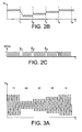
les
figures 3A et3B illustrent une suite de symboles et des niveaux de modulation correspondants,theFigures 3A and3B illustrate a sequence of symbols and corresponding modulation levels, -
la
figure 4 représente diverses étapes d'un procédé selon l'invention,thefigure 4 represents various steps of a process according to the invention, -
les
figures 5A - 5B illustrent un dispositif selon l'invention,theFigures 5A - 5B illustrate a device according to the invention, -
la
figure 6 représente un exemple de préambule,thefigure 6 is an example of a preamble, -
la
figure 7 représente des signaux obtenus à diverses étapes de traitement selon l'invention,thefigure 7 represents signals obtained at various stages of treatment according to the invention, -
les
figures 8 et 9 représentent, selon l'invention, un système à 4 niveaux et des résultats de comparaison de sortie d'un filtre et de seuils.theFigures 8 and 9 represent, according to the invention, a 4-level system and comparison results of a filter output and thresholds.
Pour plus de clarté, on précise qu'on utilise le vocabulaire suivant :
- les symboles utilisés : ils sont en nombre lié au nombre de bits émis simultanément par la station de base 2 (
figure 1A ) ; si ce nombre de bits est N, il faut 2N symboles différents, - le niveau de modulation est la valeur crête du champ électromagnétique émis par le
lecteur 2. Il faut au minimum autant de niveaux de modulation que de symboles différents. Le niveau de modulation est codé de (2N -1) à 0, - le saut est un nombre signé (+d, ou -d, d entier naturel) indiquant la différence entre le niveau de modulation du symbole Tn et celui du symbole T(n+1).
- le durée d'un symbole est le temps de transfert d'un symbole entre le lecteur et le transpondeur.
- the symbols used: they are in number linked to the number of bits transmitted simultaneously by the base station 2 (
Figure 1A ); if this number of bits is N, it takes 2 N different symbols, - the modulation level is the peak value of the electromagnetic field emitted by the
reader 2. It takes at least as many modulation levels as different symbols. The modulation level is coded from (2 N -1) to 0, - the jump is a signed number (+ d, or -d, d natural integer) indicating the difference between the modulation level of the symbol T n and that of the symbol T (n + 1) .
- the duration of a symbol is the transfer time of a symbol between the reader and the transponder.
Les
Selon l'invention, tout déplacement ou saut possible à partir de chaque niveau de modulation est préalablement répertorié et mémorisé, par exemple à l'aide d'un signal dit préambule (dont un exemple est donné plus loin en liaison avec la
On identifie donc les niveaux réels de variation, ou les sauts réels, à partir de chaque niveau de modulation, et on affecte à chacun de ces sauts réels une valeur de seuilSo we identify the actual levels of variation, or actual jumps, from each level of modulation, and we assign to each of these real jumps a threshold value
Aux sauts mesurés positifs (respectivement négatifs) hors de la gamme des sauts possibles, on affecte la plus grande (respectivement la plus petite) valeur autorisée de saut.At positive (respectively negative) measured jumps out of the range of possible jumps, the largest (respectively the smallest) allowed jump value is assigned.
Un procédé de démodulation selon l'invention est par exemple celui illustré en
- a) On procède d'abord à un filtrage passe - bas du signal signe Vc (étape S1), ce signal signe étant représenté en exemple sur la
figure 2C , - b) on compare chaque valeur du signal filtré à des seuils pour déterminer la variation de champ détecté (étape S2),
- c) on calcule le niveau reçu à partir de la variation du saut et du niveau précédent (étape S3).
- a) Low-pass filtering of the sign signal V c (step S1) is first carried out, this sign signal being represented as an example on the
Figure 2C , - b) comparing each value of the filtered signal with thresholds to determine the detected field variation (step S2),
- c) calculating the level received from the variation of the jump and the previous level (step S3).
Selon l'invention, un procédé de démodulation d'une information émise par modulation d'amplitude d'un signal par un lecteur vers un transpondeur, peut donc comporter:
- pour chaque saut à partir d'un niveau donné de ladite modulation, l'identification des valeurs de variation possibles à partir de ce niveau,
- la détermination du saut puis le calcul du nouveau niveau de modulation en fonction du niveau de modulation antérieur et de la valeur du saut.
- for each jump from a given level of said modulation, identifying the possible values of variation from that level,
- determining the jump and then calculating the new modulation level according to the previous modulation level and the jump value.
Un procédé selon l'invention peut être implémenté dans un transpondeur de manière numérique, par exemple à l'aide d'un filtre, la sortie du filtre étant envoyée à un dispositif tel que par exemple celui illustré en
La
Ces derniers produisent une tension de commande d'une impédance de charge 11.These produce a control voltage of a
Un circuit 18 de traitement numérique fournit des signaux numériques représentatifs des données transmises.A
Le convertisseur 16 à n bits est situé dans la boucle de régulation, entre les moyens 12 de redressement et les moyens 14 de commande. Le convertisseur 16 est, de préférence, un convertisseur à un bit (n=1), qui peut comporter un simple comparateur. Une très faible résolution est ainsi obtenue, qui permet de réduire au minimum le nombre de composants, et qui est compensée par une forte résolution dans le temps, obtenue en cadençant le convertisseur 16 à une fréquence de sur-échantillonnage très supérieure à la fréquence des données transmises par la station fixe 2.The n-
La fréquence de sur- échantillonnage est par exemple déterminée par un circuit d'horloge fournissant des signaux d'horloge Ck à une entrée de cadencement du convertisseur 16. A titre d'exemple, pour une fréquence de données de l'ordre de 200kHz, la fréquence de sur-échantillonage peut avantageusement être comprise entre 10 et 20MHz.The oversampling frequency is for example determined by a clock circuit providing clock signals C k to a clock input of the
Bien que les signaux numériques de sortie du convertisseur 16 contiennent les informations nécessaires à la récupération des données transmises par la station fixe 2, ces signaux numériques ne sont pas directement exploitables.Although the digital output signals of the
La sortie du convertisseur 16, connectée au circuit de commande 14, est donc connectée à l'entrée d'un circuit de traitement numérique 18 destiné à fournir, sur N bits, les données démodulées.The output of the
Le fonctionnement du circuit de démodulation de l'objet portatif de la
Par exemple, ce signal a la forme d'une rampe de tension montante lorsque la sortie des moyens 16 est à 1 et d'une rampe de tension descendante lorsque cette sortie est à zéro. La tension de commande Vc, obtenue en sortie des moyens de commande 14, n'est donc jamais statique. Ainsi, après une période transitoire, lorsque la boucle de régulation est en position d'équilibre, la tension de commande Vc a la forme d'un signal en dents de scie autour d'un niveau moyen (voir
Dans l'exemple illustré en
Dans cet exemple, une diminution du niveau du champ magnétique H entraîne l'émission d'une séquence de zéros consécutifs plus longue que lors de l'asservissement, provoquant une diminution de l'amplitude moyenne de la tension de commande Vc. De manière analogue, une augmentation du niveau du champ magnétique émis se traduit par l'émission d'une séquence de « 1 » consécutifs, plus longue que lors de l'asservissement, provoquant une augmentation de l'amplitude moyenne de la tension de commande Vc. Le nombre de O ou de 1 consécutifs croît avec l'amplitude du saut de la force électromotrice.In this example, a decrease in the level of the magnetic field H causes the emission of a sequence of consecutive zeros longer than during the servo-control, causing a decrease in the average amplitude of the control voltage V c . Similarly, an increase in the level of the emitted magnetic field results in the emission of a consecutive sequence of "1", which is longer than during servo-control, causing an increase in the average amplitude of the control voltage. V c . The number of consecutive O or 1 increases with the amplitude of the jump of the electromotive force.
Les signaux numériques de sortie du convertisseur 16 contiennent donc une information représentative du signe et de l'amplitude de la variation du niveau de la fem générée par le champ H, autrement dit une information représentative de la dérivée de l'enveloppe de la force électromotrice ou du champ magnétique. Le circuit de traitement numérique 18 comporte donc au moins une fonction d'intégration numérique. Les fonctions d'intégration du circuit de commande 14 et/ou du circuit de traitement numérique 18 peuvent être réalisées au moyen d'intégrateurs et/ou de filtres passe - bas.The digital output signals of the
Ainsi, la boucle de régulation de la
La
Un tel dispositif comporte des moyens 50 comparateurs, pour comparer la sortie du filtre 40 (lequel est situé à l'entrée du bloc 18 de traitement numérique,
Cette table de seuil est par exemple alimentée lors d'une phase ou de préambule qui comporte tous les déplacements possibles, comme illustré sur la
Les moyens 60 sont des moyens additionneurs, tandis que la référence 70 désigne un registre.The means 60 are adding means, while the
En fonctionnement, la fréquence de travail est la fréquence symbole. A l'instant tn+1, la table seuil 80 est adressée par la valeur du niveau de modulation pendant le temps tn. Cette valeur donne donc le niveau de modulation qui a été précédemment calculé pour l'instant tn.In operation, the working frequency is the symbol frequency. At time t n + 1 , the threshold table 80 is addressed by the value of the modulation level during the time t n . This value therefore gives the level of modulation that was previously calculated for the moment t n .
Par ailleurs, la sortie du filtre 40 est comparée aux seuils contenus dans la table 80, et la sortie du comparateur 50 donne le saut dep (tn+1) suivant la logique décrite ci-dessus. Ce saut est additionné au niveau niveau (tn) pour donner le niveau reçu au temps tn+1.On the other hand, the output of the
La
- B0 représente le signal en sortie du convertisseur 16,
- Fir représente la sortie du filtre,
- Endts représente la durée du symbole,
- Dep représente la variation de champ détectée,
- Niv représente le champ détecté par le transpondeur.
- B 0 represents the signal at the output of the
converter 16, - Fir represents the output of the filter,
- Endts represents the duration of the symbol,
- Dep represents the detected field variation,
- Lv represents the field detected by the transponder.
A chaque impulsion Endts, représentant la fréquence symbole, la sortie du filtre Fir est comparée aux seuils. On obtient alors les sauts Dep d'où on déduit le niveau de modulation Niv.At each pulse Endts, representing the symbol frequency, the output of the filter Fir is compared to the thresholds. We then obtain the jumps Dep from which we deduce the level of modulation Niv.
Un exemple va illustrer ce procédé.An example will illustrate this process.
Cet exemple concerne une modulation à 4 niveaux, notés de 0 à 3, et représentés schématiquement sur les
Les déplacements relatifs, ou sauts, possibles, à partir des différents niveaux sont :
- à partir du Niveau 0 : +1 (
niveau 0 => 1), +2 (niveau 0 => 2), +3 (niveau 0 => 3), - à partir du Niveau 1 : +1 (
niveau 1 => 2), +2 (niveau 1 => 3), -1 (niveau 1 => 0), - à partir du Niveau 2 : +1 (
niveau 2 => 3), -1 (niveau 2 => 1), -2 (niveau 2 => 0), - à partir du Niveau 3 : -1 (
niveau 3 => 2), -2 (niveau 3 => 1), -3 (niveau 3 => 0).
- from Level 0: +1 (
level 0 => 1), +2 (level 0 => 2), +3 (level 0 => 3), - from Level 1: +1 (
level 1 => 2), +2 (level 1 => 3), -1 (level 1 => 0), - from Level 2: +1 (
level 2 => 3), -1 (level 2 => 1), -2 (level 2 => 0), - from Level 3: -1 (
level 3 => 2), -2 (level 3 => 1), -3 (level 3 => 0).
A priori, pour une modulation à 4 niveaux seuls 6 seuils sont nécessaires (+1,+2,+3,-1,-2,-3). En comparant la sortie du filtre à ces 6 niveaux et en connaissant le niveau précédent, on peut calculer le nouveau niveau de modulation et donc la valeur du symbole émis par le lecteur.A priori, for a modulation with 4 levels only 6 thresholds are necessary (+ 1, + 2, + 3, -1, -2, -3). Comparing the output of the filter with these 6 levels and knowing the previous level, we can calculate the new level of modulation and therefore the value of the symbol emitted by the reader.
Le saut peut être calculé de la manière suivante :
- si filtre > seuil(+3) alors saut = +3 ;
- sinon, si seuil(+3) > filtre > seuil(+2) alors saut = +2 ;
- sinon, si seuil(+2) > filtre > seuil(+1) alors saut = +1 ;
- sinon, si seuil(+1) > filtre > seuil(-1) alors saut = 0 ;
- sinon, si seuil(-1) > filtre > seuil(-2) alors saut = -1 ;
- sinon, si seuil(-2) > filtre > seuil(-3) alors saut = -2 ;
- sinon : saut = -3.
- if filter> threshold (+3) then jump = +3;
- if not, if threshold (+3)>filter> threshold (+2) then jump = +2;
- if not, if threshold (+2)>filter> threshold (+1) then jump = +1;
- otherwise, if threshold (+1)>filter> threshold (-1) then jump = 0;
- otherwise, if threshold (-1)>filter> threshold (-2) then jump = -1;
- otherwise, if threshold (-2)>filter> threshold (-3) then jump = -2;
- otherwise: jump = -3.
Comme déjà expliqué ci-dessus, les seuils, pour chaque niveau, ne sont pas identiques, ni nécessairement linéairement répartis, et le convertisseur dans le transpondeur n'est pas parfaitement linéaire. D'autre part, on ne prend pas en compte le fait que chaque niveau n'a que 3 sauts possibles (+ le saut nul).As already explained above, the thresholds for each level are not identical, nor necessarily linearly distributed, and the converter in the transponder is not perfectly linear. On the other hand, we do not take into account the fact that each level has only 3 possible jumps (+ the null jump).
Comme expliqué ci-dessus, selon l'invention, pour pallier les défauts de non linéarité, on peut calculer préalablement, pour chaque niveau, ses propres seuils de sauts autorisés.As explained above, according to the invention, to overcome the nonlinearity defects, it is possible to calculate beforehand, for each level, its own thresholds of allowed jumps.
Une transaction entre le lecteur 2 et le transpondeur 4 débute alors par exemple par un préambule, défini de telle manière qu'il contienne tous les sauts relatifs existants pour tous les niveaux possibles.A transaction between the
Pendant cette phase, le transpondeur va ainsi pouvoir définir tous les seuils de sauts réels.During this phase, the transponder will be able to define all the actual jump thresholds.
La
Le tableau I indique, pour chaque Ti le seuil(s) calculé pour le niveau (n).
On dispose ainsi d'un tableau de 12 coefficients (3 coefficients pour chacun des 4 niveaux).This gives us a table of 12 coefficients (3 coefficients for each of the 4 levels).
Pour tenir compte des sauts interdits pour chaque niveau, ce tableau peut être complété :
- pour les sauts positifs interdits, par la plus grande valeur possible du calcul du filtre ;
- pour les sauts négatifs interdits, par la plus petite valeur possible du calcul du filtre.
- for forbidden positive jumps, by the greatest possible value of the calculation of the filter;
- for the prohibited negative jumps, by the smallest possible value of the calculation of the filter.
On obtient alors un tableau de 24 coefficients (6 seuils pour chacun des 4 niveaux).We then obtain a table of 24 coefficients (6 thresholds for each of the 4 levels).
Seuil(Ti) représente le seuil calculé ou autorisé à l'instant Ti (voir Tableau I et
L'application du procédé expliqué ci-dessus conduit donc au tableau II suivant :
Dans le cas où le filtre est calculé sur 9 bits, les seuils à -256 (respectivement +255) sont interdits et se voient affecter le niveau minimal (respectivement maximal).In the case where the filter is calculated on 9 bits, the thresholds at -256 (respectively +255) are prohibited and are assigned the minimum level (respectively maximum).
La démodulation numérique proposée permet d'utiliser efficacement la sortie d'un convertisseur sigma delta 20, positionné comme illustré sur la
En outre, dans le cas du multi-niveaux (nombre de niveaux strictement supérieur à 2), la gestion de seuils différents par niveau et la gestion (ou la correction) des sauts interdits améliorent notablement le rapport signal à bruit et augmentent la qualité de démodulation.Moreover, in the case of multilevel (number of levels strictly greater than 2), the management of different thresholds by level and management (or correction) of the prohibited jumps significantly improve the signal-to-noise ratio and increase the quality of the signal. demodulation.
Un système selon l'invention a été réalisé, avec une durée symbole de 1,18 µs, 4 niveaux par symbole (soit 2 bits par symbole). Un tel système a permis de réaliser une transmission de données à 1,7 Mbits/S.A system according to the invention has been realized, with a symbol duration of 1.18 μs, 4 levels per symbol (
Claims (7)
- Method for demodulating information remitted by amplitude modulation by a reader (2) to a transponder (4), the number of modulation levels N being greater than or equal to 2, allowable threshold values being stored in advance and associated with each modulation level, comprising:- a step to compare variations of a slaving Voltage (Vc) of the transponder (4), with said threshold values, and to determine a value of real skip of amplitude modulation level from the result of this comparison,- a step to add this skip to a first previous amplitude modulation level to determine a second modulation amplitude level.
- Method according to claim 1, including a step to send a preamble containing all possible skips for all modulation levels, before sending each signal from the reader (2) to the transponder (4).
- Method according to one of claims 1 or 2, also including calculation of a new slaving voltage (Vc) as a function of the previous voltage level and the authorized variation value, for each slaving voltage level.
- Device for demodulating information remitted by amplitude modulation by a reader to a transponder, the number of modulation levels N being greater than or equal to 2, characterized in that it comprises:- means (80) of storing values of possible variations of a slaving voltage signal of the transponder, for each level of the said modulation, starting from this level,- means (50, 60, 70) of calculating the corresponding allowable level skip during each transition, and of calculating the new slaving voltage signal level as a function of a previous signal level.
- Device according to claim 4, also comprising means (10) forming an antenna, load impedance means (11) at the antenna terminals, and means (12, 16, 14) forming a voltage regulation loop at the terminals of the load impedance.
- Device according to claim 5, the means forming regulation comprising means (12) of rectifying the voltage at the antenna terminals, and control means (14) to modify the impedance as a function of the output from the rectification means (12).
- Device according to claim 6, also comprising demodulation means comprising analogue-digital conversion means (16) between the control means (14) and the rectification means (12).
Applications Claiming Priority (1)
| Application Number | Priority Date | Filing Date | Title |
|---|---|---|---|
| FR0550727A FR2883433B1 (en) | 2005-03-21 | 2005-03-21 | MULTINIVE DEMODULATION METHOD AND DEVICE. |
Publications (2)
| Publication Number | Publication Date |
|---|---|
| EP1705604A1 EP1705604A1 (en) | 2006-09-27 |
| EP1705604B1 true EP1705604B1 (en) | 2009-09-23 |
Family
ID=35064619
Family Applications (1)
| Application Number | Title | Priority Date | Filing Date |
|---|---|---|---|
| EP06111387A Not-in-force EP1705604B1 (en) | 2005-03-21 | 2006-03-20 | Multilevel demodulation method and device |
Country Status (6)
| Country | Link |
|---|---|
| US (1) | US7525374B2 (en) |
| EP (1) | EP1705604B1 (en) |
| JP (1) | JP4868903B2 (en) |
| AT (1) | ATE443901T1 (en) |
| DE (1) | DE602006009331D1 (en) |
| FR (1) | FR2883433B1 (en) |
Families Citing this family (9)
| Publication number | Priority date | Publication date | Assignee | Title |
|---|---|---|---|---|
| FR2875976B1 (en) * | 2004-09-27 | 2006-11-24 | Commissariat Energie Atomique | SECURE CONTACTLESS COMMUNICATION DEVICE AND METHOD |
| US7737731B1 (en) | 2005-10-20 | 2010-06-15 | Marvell International Ltd. | High data rate envelope detector for high speed optical storage application |
| US20100127830A1 (en) * | 2007-04-20 | 2010-05-27 | Finn Nielsen | Portable card with an rfid coil |
| IL193504A (en) * | 2008-08-17 | 2013-02-28 | Michael Braiman | Coded system for radio frequency communication |
| FR2939580A1 (en) * | 2008-12-09 | 2010-06-11 | Commissariat Energie Atomique | PORTABLE OBJECT INDUCTIVELY COUPLED TO A FIXED STATION AND COMPRISING MEANS FOR CONTROLLING THE GAIN |
| SG11201704445XA (en) | 2014-12-19 | 2017-07-28 | Cardlab Aps | A method and an assembly for generating a magnetic field and a method of manufacturing an assembly |
| EP3035230A1 (en) | 2014-12-19 | 2016-06-22 | Cardlab ApS | A method and an assembly for generating a magnetic field |
| EP3082071A1 (en) | 2015-04-17 | 2016-10-19 | Cardlab ApS | Device for and method of outputting a magnetic field |
| GB2560314B (en) * | 2017-03-06 | 2022-03-30 | Safran Electrical & Power | An electrical machine |
Family Cites Families (8)
| Publication number | Priority date | Publication date | Assignee | Title |
|---|---|---|---|---|
| JPH07123121A (en) * | 1992-04-02 | 1995-05-12 | Shinko Electric Co Ltd | Demodulation system |
| US5825243A (en) * | 1995-10-30 | 1998-10-20 | Casio Computer Co., Ltd. | Apparatus and method for demodulating multi-level signal |
| JPH10163877A (en) * | 1996-11-28 | 1998-06-19 | Sony Corp | Threshold control circuit of multi-valued comparator for demodulation circuit |
| US6078627A (en) * | 1997-12-18 | 2000-06-20 | Advanced Micro Devices, Inc. | Circuit and method for multilevel signal decoding, descrambling, and error detection |
| JP3522745B2 (en) * | 2000-10-05 | 2004-04-26 | 松下電器産業株式会社 | Transmission line encoding method and decoding method |
| FR2853479A1 (en) * | 2003-04-07 | 2004-10-08 | Commissariat Energie Atomique | Remote control device for e.g. object identification application, has portable object equipped with antenna coil that is coupled inductively to another antenna coil of fixed station and including load impedance modulation circuit |
| JP2005012254A (en) * | 2003-06-16 | 2005-01-13 | Toshiba Tec Corp | Wireless communication apparatus |
| FR2859842B1 (en) * | 2003-09-17 | 2006-02-10 | Commissariat Energie Atomique | PORTABLE MULTINIVE DEMODULATION OBJECT, INDUCTIVELY COUPLED TO A FIXED STATION |
-
2005
- 2005-03-21 FR FR0550727A patent/FR2883433B1/en not_active Expired - Fee Related
-
2006
- 2006-03-20 DE DE602006009331T patent/DE602006009331D1/en active Active
- 2006-03-20 EP EP06111387A patent/EP1705604B1/en not_active Not-in-force
- 2006-03-20 AT AT06111387T patent/ATE443901T1/en not_active IP Right Cessation
- 2006-03-21 US US11/386,551 patent/US7525374B2/en not_active Expired - Fee Related
- 2006-03-22 JP JP2006078203A patent/JP4868903B2/en not_active Expired - Fee Related
Also Published As
| Publication number | Publication date |
|---|---|
| JP4868903B2 (en) | 2012-02-01 |
| US7525374B2 (en) | 2009-04-28 |
| FR2883433B1 (en) | 2007-04-20 |
| US20060225555A1 (en) | 2006-10-12 |
| DE602006009331D1 (en) | 2009-11-05 |
| FR2883433A1 (en) | 2006-09-22 |
| EP1705604A1 (en) | 2006-09-27 |
| JP2006279956A (en) | 2006-10-12 |
| ATE443901T1 (en) | 2009-10-15 |
Similar Documents
| Publication | Publication Date | Title |
|---|---|---|
| EP1705604B1 (en) | Multilevel demodulation method and device | |
| CA2245912C (en) | Data exchange system by contactless communication between a terminal and remote powered portable objects | |
| EP1774458B1 (en) | Modulation of charge in an electromagnetic transponder | |
| EP1312032B1 (en) | High sensitivity reader for passive transponders | |
| FR2792134A1 (en) | DISTANCE DETECTION BETWEEN AN ELECTROMAGNETIC TRANSPONDER AND A TERMINAL | |
| EP1045336A1 (en) | Close-coupled method of operation of an electromagnetic transpondersystem | |
| EP0903689A1 (en) | Demodulator for contactless chip card | |
| EP1143377B1 (en) | Active transponder including means to modify the maximum communication distance | |
| EP1665573B1 (en) | Portable object having multi-level demodulation and being inductively coupled to a fixed station | |
| FR2946821A1 (en) | ADAPTIVE DEMODULATOR | |
| FR2636740A1 (en) | ANALOG SIGNAL LOGARITHMIC ENVELOPE DETECTOR | |
| CA2144670C (en) | Digital device for the wideband recovery of carriers | |
| WO2001071997A1 (en) | Demodulator of an amplitude-modulated alternating signal | |
| EP1705601B1 (en) | Two-level demodulation method and device | |
| EP0473731B1 (en) | Method and device for comparing two variable analog signals | |
| CN108933748A (en) | Realize the demodulation method and system of the FM signal of locking frequency variation | |
| EP1335486A1 (en) | Demodulator for contactless chip cards | |
| EP0541431A1 (en) | Method and circuit for reproducing a clock signal, clocking the transmission of the received signals | |
| FR2768881A1 (en) | DEVICE FOR CONTROLLING THE SAMPLING OF A SIGNAL CARRYING BINARY INFORMATION ENCODED ACCORDING TO TWO-PHASE CODING | |
| FR2861931A1 (en) | DIGITAL DEMODULATOR WITH LOW FREQUENCY SAMPLING | |
| EP1421683A2 (en) | Wireless signal amplification system and a television signal decoder comprising one such system | |
| FR2879378A1 (en) | Radio frequency signal transmission method for electromagnetic transponder system, involves controlling gain of transmitter amplifier by microcontroller to control modulation factor of transmission signal | |
| FR2713853A1 (en) | System for receiving or reading information series. | |
| WO2005067140A1 (en) | Automatic gain control of a digital receiver for receiving discontinuous envelope signals | |
| WO2000051062A1 (en) | Contactless card reader comprising a phase demodulation detector |
Legal Events
| Date | Code | Title | Description |
|---|---|---|---|
| PUAI | Public reference made under article 153(3) epc to a published international application that has entered the european phase |
Free format text: ORIGINAL CODE: 0009012 |
|
| AK | Designated contracting states |
Kind code of ref document: A1 Designated state(s): AT BE BG CH CY CZ DE DK EE ES FI FR GB GR HU IE IS IT LI LT LU LV MC NL PL PT RO SE SI SK TR |
|
| AX | Request for extension of the european patent |
Extension state: AL BA HR MK YU |
|
| RAP1 | Party data changed (applicant data changed or rights of an application transferred) |
Owner name: COMMISSARIAT A L'ENERGIE ATOMIQUE |
|
| 17P | Request for examination filed |
Effective date: 20070316 |
|
| AKX | Designation fees paid |
Designated state(s): AT BE BG CH CY CZ DE DK EE ES FI FR GB GR HU IE IS IT LI LT LU LV MC NL PL PT RO SE SI SK TR |
|
| GRAP | Despatch of communication of intention to grant a patent |
Free format text: ORIGINAL CODE: EPIDOSNIGR1 |
|
| GRAS | Grant fee paid |
Free format text: ORIGINAL CODE: EPIDOSNIGR3 |
|
| GRAA | (expected) grant |
Free format text: ORIGINAL CODE: 0009210 |
|
| AK | Designated contracting states |
Kind code of ref document: B1 Designated state(s): AT BE BG CH CY CZ DE DK EE ES FI FR GB GR HU IE IS IT LI LT LU LV MC NL PL PT RO SE SI SK TR |
|
| REG | Reference to a national code |
Ref country code: GB Ref legal event code: FG4D Free format text: NOT ENGLISH |
|
| REG | Reference to a national code |
Ref country code: CH Ref legal event code: EP |
|
| REG | Reference to a national code |
Ref country code: IE Ref legal event code: FG4D |
|
| REF | Corresponds to: |
Ref document number: 602006009331 Country of ref document: DE Date of ref document: 20091105 Kind code of ref document: P |
|
| PG25 | Lapsed in a contracting state [announced via postgrant information from national office to epo] |
Ref country code: FI Free format text: LAPSE BECAUSE OF FAILURE TO SUBMIT A TRANSLATION OF THE DESCRIPTION OR TO PAY THE FEE WITHIN THE PRESCRIBED TIME-LIMIT Effective date: 20090923 Ref country code: LT Free format text: LAPSE BECAUSE OF FAILURE TO SUBMIT A TRANSLATION OF THE DESCRIPTION OR TO PAY THE FEE WITHIN THE PRESCRIBED TIME-LIMIT Effective date: 20090923 Ref country code: SE Free format text: LAPSE BECAUSE OF FAILURE TO SUBMIT A TRANSLATION OF THE DESCRIPTION OR TO PAY THE FEE WITHIN THE PRESCRIBED TIME-LIMIT Effective date: 20090923 |
|
| LTIE | Lt: invalidation of european patent or patent extension |
Effective date: 20090923 |
|
| PG25 | Lapsed in a contracting state [announced via postgrant information from national office to epo] |
Ref country code: LV Free format text: LAPSE BECAUSE OF FAILURE TO SUBMIT A TRANSLATION OF THE DESCRIPTION OR TO PAY THE FEE WITHIN THE PRESCRIBED TIME-LIMIT Effective date: 20090923 Ref country code: PL Free format text: LAPSE BECAUSE OF FAILURE TO SUBMIT A TRANSLATION OF THE DESCRIPTION OR TO PAY THE FEE WITHIN THE PRESCRIBED TIME-LIMIT Effective date: 20090923 Ref country code: SI Free format text: LAPSE BECAUSE OF FAILURE TO SUBMIT A TRANSLATION OF THE DESCRIPTION OR TO PAY THE FEE WITHIN THE PRESCRIBED TIME-LIMIT Effective date: 20090923 |
|
| NLV1 | Nl: lapsed or annulled due to failure to fulfill the requirements of art. 29p and 29m of the patents act | ||
| PG25 | Lapsed in a contracting state [announced via postgrant information from national office to epo] |
Ref country code: CY Free format text: LAPSE BECAUSE OF FAILURE TO SUBMIT A TRANSLATION OF THE DESCRIPTION OR TO PAY THE FEE WITHIN THE PRESCRIBED TIME-LIMIT Effective date: 20090923 |
|
| REG | Reference to a national code |
Ref country code: IE Ref legal event code: FD4D |
|
| PG25 | Lapsed in a contracting state [announced via postgrant information from national office to epo] |
Ref country code: RO Free format text: LAPSE BECAUSE OF FAILURE TO SUBMIT A TRANSLATION OF THE DESCRIPTION OR TO PAY THE FEE WITHIN THE PRESCRIBED TIME-LIMIT Effective date: 20090923 Ref country code: EE Free format text: LAPSE BECAUSE OF FAILURE TO SUBMIT A TRANSLATION OF THE DESCRIPTION OR TO PAY THE FEE WITHIN THE PRESCRIBED TIME-LIMIT Effective date: 20090923 Ref country code: CZ Free format text: LAPSE BECAUSE OF FAILURE TO SUBMIT A TRANSLATION OF THE DESCRIPTION OR TO PAY THE FEE WITHIN THE PRESCRIBED TIME-LIMIT Effective date: 20090923 Ref country code: PT Free format text: LAPSE BECAUSE OF FAILURE TO SUBMIT A TRANSLATION OF THE DESCRIPTION OR TO PAY THE FEE WITHIN THE PRESCRIBED TIME-LIMIT Effective date: 20100125 Ref country code: ES Free format text: LAPSE BECAUSE OF FAILURE TO SUBMIT A TRANSLATION OF THE DESCRIPTION OR TO PAY THE FEE WITHIN THE PRESCRIBED TIME-LIMIT Effective date: 20100103 Ref country code: IE Free format text: LAPSE BECAUSE OF FAILURE TO SUBMIT A TRANSLATION OF THE DESCRIPTION OR TO PAY THE FEE WITHIN THE PRESCRIBED TIME-LIMIT Effective date: 20090923 Ref country code: IS Free format text: LAPSE BECAUSE OF FAILURE TO SUBMIT A TRANSLATION OF THE DESCRIPTION OR TO PAY THE FEE WITHIN THE PRESCRIBED TIME-LIMIT Effective date: 20100123 |
|
| PG25 | Lapsed in a contracting state [announced via postgrant information from national office to epo] |
Ref country code: SK Free format text: LAPSE BECAUSE OF FAILURE TO SUBMIT A TRANSLATION OF THE DESCRIPTION OR TO PAY THE FEE WITHIN THE PRESCRIBED TIME-LIMIT Effective date: 20090923 |
|
| PG25 | Lapsed in a contracting state [announced via postgrant information from national office to epo] |
Ref country code: AT Free format text: LAPSE BECAUSE OF FAILURE TO SUBMIT A TRANSLATION OF THE DESCRIPTION OR TO PAY THE FEE WITHIN THE PRESCRIBED TIME-LIMIT Effective date: 20090923 |
|
| PG25 | Lapsed in a contracting state [announced via postgrant information from national office to epo] |
Ref country code: NL Free format text: LAPSE BECAUSE OF FAILURE TO SUBMIT A TRANSLATION OF THE DESCRIPTION OR TO PAY THE FEE WITHIN THE PRESCRIBED TIME-LIMIT Effective date: 20090923 Ref country code: DK Free format text: LAPSE BECAUSE OF FAILURE TO SUBMIT A TRANSLATION OF THE DESCRIPTION OR TO PAY THE FEE WITHIN THE PRESCRIBED TIME-LIMIT Effective date: 20090923 |
|
| PLBE | No opposition filed within time limit |
Free format text: ORIGINAL CODE: 0009261 |
|
| STAA | Information on the status of an ep patent application or granted ep patent |
Free format text: STATUS: NO OPPOSITION FILED WITHIN TIME LIMIT |
|
| 26N | No opposition filed |
Effective date: 20100624 |
|
| BERE | Be: lapsed |
Owner name: COMMISSARIAT A L'ENERGIE ATOMIQUE Effective date: 20100331 |
|
| PG25 | Lapsed in a contracting state [announced via postgrant information from national office to epo] |
Ref country code: MC Free format text: LAPSE BECAUSE OF NON-PAYMENT OF DUE FEES Effective date: 20100331 Ref country code: GR Free format text: LAPSE BECAUSE OF FAILURE TO SUBMIT A TRANSLATION OF THE DESCRIPTION OR TO PAY THE FEE WITHIN THE PRESCRIBED TIME-LIMIT Effective date: 20091224 |
|
| REG | Reference to a national code |
Ref country code: CH Ref legal event code: PL |
|
| PG25 | Lapsed in a contracting state [announced via postgrant information from national office to epo] |
Ref country code: BE Free format text: LAPSE BECAUSE OF NON-PAYMENT OF DUE FEES Effective date: 20100331 Ref country code: CH Free format text: LAPSE BECAUSE OF NON-PAYMENT OF DUE FEES Effective date: 20100331 Ref country code: LI Free format text: LAPSE BECAUSE OF NON-PAYMENT OF DUE FEES Effective date: 20100331 |
|
| PG25 | Lapsed in a contracting state [announced via postgrant information from national office to epo] |
Ref country code: LU Free format text: LAPSE BECAUSE OF NON-PAYMENT OF DUE FEES Effective date: 20100320 Ref country code: HU Free format text: LAPSE BECAUSE OF FAILURE TO SUBMIT A TRANSLATION OF THE DESCRIPTION OR TO PAY THE FEE WITHIN THE PRESCRIBED TIME-LIMIT Effective date: 20100324 Ref country code: BG Free format text: LAPSE BECAUSE OF FAILURE TO SUBMIT A TRANSLATION OF THE DESCRIPTION OR TO PAY THE FEE WITHIN THE PRESCRIBED TIME-LIMIT Effective date: 20090923 |
|
| PG25 | Lapsed in a contracting state [announced via postgrant information from national office to epo] |
Ref country code: TR Free format text: LAPSE BECAUSE OF FAILURE TO SUBMIT A TRANSLATION OF THE DESCRIPTION OR TO PAY THE FEE WITHIN THE PRESCRIBED TIME-LIMIT Effective date: 20090923 |
|
| PGFP | Annual fee paid to national office [announced via postgrant information from national office to epo] |
Ref country code: IT Payment date: 20150326 Year of fee payment: 10 |
|
| REG | Reference to a national code |
Ref country code: FR Ref legal event code: PLFP Year of fee payment: 11 |
|
| PG25 | Lapsed in a contracting state [announced via postgrant information from national office to epo] |
Ref country code: IT Free format text: LAPSE BECAUSE OF NON-PAYMENT OF DUE FEES Effective date: 20160320 |
|
| REG | Reference to a national code |
Ref country code: FR Ref legal event code: PLFP Year of fee payment: 12 |
|
| REG | Reference to a national code |
Ref country code: FR Ref legal event code: PLFP Year of fee payment: 13 |
|
| PGFP | Annual fee paid to national office [announced via postgrant information from national office to epo] |
Ref country code: DE Payment date: 20200311 Year of fee payment: 15 Ref country code: GB Payment date: 20200323 Year of fee payment: 15 |
|
| PGFP | Annual fee paid to national office [announced via postgrant information from national office to epo] |
Ref country code: FR Payment date: 20200331 Year of fee payment: 15 |
|
| REG | Reference to a national code |
Ref country code: DE Ref legal event code: R119 Ref document number: 602006009331 Country of ref document: DE |
|
| GBPC | Gb: european patent ceased through non-payment of renewal fee |
Effective date: 20210320 |
|
| PG25 | Lapsed in a contracting state [announced via postgrant information from national office to epo] |
Ref country code: FR Free format text: LAPSE BECAUSE OF NON-PAYMENT OF DUE FEES Effective date: 20210331 Ref country code: GB Free format text: LAPSE BECAUSE OF NON-PAYMENT OF DUE FEES Effective date: 20210320 Ref country code: DE Free format text: LAPSE BECAUSE OF NON-PAYMENT OF DUE FEES Effective date: 20211001 |