EP1705575A2 - Speichersystem - Google Patents
Speichersystem Download PDFInfo
- Publication number
- EP1705575A2 EP1705575A2 EP06251030A EP06251030A EP1705575A2 EP 1705575 A2 EP1705575 A2 EP 1705575A2 EP 06251030 A EP06251030 A EP 06251030A EP 06251030 A EP06251030 A EP 06251030A EP 1705575 A2 EP1705575 A2 EP 1705575A2
- Authority
- EP
- European Patent Office
- Prior art keywords
- computer
- storage
- storage area
- target device
- information
- Prior art date
- Legal status (The legal status is an assumption and is not a legal conclusion. Google has not performed a legal analysis and makes no representation as to the accuracy of the status listed.)
- Granted
Links
Images










Classifications
-
- G—PHYSICS
- G06—COMPUTING OR CALCULATING; COUNTING
- G06F—ELECTRIC DIGITAL DATA PROCESSING
- G06F3/00—Input arrangements for transferring data to be processed into a form capable of being handled by the computer; Output arrangements for transferring data from processing unit to output unit, e.g. interface arrangements
- G06F3/06—Digital input from, or digital output to, record carriers, e.g. RAID, emulated record carriers or networked record carriers
- G06F3/0601—Interfaces specially adapted for storage systems
- G06F3/0602—Interfaces specially adapted for storage systems specifically adapted to achieve a particular effect
- G06F3/0604—Improving or facilitating administration, e.g. storage management
-
- G—PHYSICS
- G06—COMPUTING OR CALCULATING; COUNTING
- G06F—ELECTRIC DIGITAL DATA PROCESSING
- G06F3/00—Input arrangements for transferring data to be processed into a form capable of being handled by the computer; Output arrangements for transferring data from processing unit to output unit, e.g. interface arrangements
- G06F3/06—Digital input from, or digital output to, record carriers, e.g. RAID, emulated record carriers or networked record carriers
- G06F3/0601—Interfaces specially adapted for storage systems
- G06F3/0602—Interfaces specially adapted for storage systems specifically adapted to achieve a particular effect
- G06F3/0604—Improving or facilitating administration, e.g. storage management
- G06F3/0607—Improving or facilitating administration, e.g. storage management by facilitating the process of upgrading existing storage systems, e.g. for improving compatibility between host and storage device
-
- G—PHYSICS
- G06—COMPUTING OR CALCULATING; COUNTING
- G06F—ELECTRIC DIGITAL DATA PROCESSING
- G06F3/00—Input arrangements for transferring data to be processed into a form capable of being handled by the computer; Output arrangements for transferring data from processing unit to output unit, e.g. interface arrangements
- G06F3/06—Digital input from, or digital output to, record carriers, e.g. RAID, emulated record carriers or networked record carriers
- G06F3/0601—Interfaces specially adapted for storage systems
- G06F3/0628—Interfaces specially adapted for storage systems making use of a particular technique
- G06F3/0629—Configuration or reconfiguration of storage systems
- G06F3/0631—Configuration or reconfiguration of storage systems by allocating resources to storage systems
-
- G—PHYSICS
- G06—COMPUTING OR CALCULATING; COUNTING
- G06F—ELECTRIC DIGITAL DATA PROCESSING
- G06F3/00—Input arrangements for transferring data to be processed into a form capable of being handled by the computer; Output arrangements for transferring data from processing unit to output unit, e.g. interface arrangements
- G06F3/06—Digital input from, or digital output to, record carriers, e.g. RAID, emulated record carriers or networked record carriers
- G06F3/0601—Interfaces specially adapted for storage systems
- G06F3/0668—Interfaces specially adapted for storage systems adopting a particular infrastructure
- G06F3/067—Distributed or networked storage systems, e.g. storage area networks [SAN], network attached storage [NAS]
Definitions
- the present invention relates to a storage system comprising a storage device system comprising a computer and a plurality of logical storage areas.
- a computer file system
- desired files storage areas
- the target device is a logical device on a storage device system recognizable as subject to access from the computer, and is provided virtually using software, or physically using hardware.
- the target devices are uniformly correlated to the storage areas, and the computer is able to access the desired storage area by identifying a target device using a port ID (e.g. an identifier for uniformly identifying a port called a WWN (World Wide Name)) and an LUN (Logical Unit Number).
- a port ID e.g. an identifier for uniformly identifying a port called a WWN (World Wide Name)
- LUN Logical Unit Number
- the data capacity that may be stored in the storage device system is limited by the target device count. Also, even when there is a not a de facto limit in the number of target devices that may be provided by the storage device system, the number of target devices increases together with an increase in the file count, and there is the problem that the target device resources for the storage device system are consumed.
- the storage device system is a system for storing data sent successively from the client computer, and when the target device resources decrease due to an increase in the number of snapshot files, the number of target devices to be allocated to the new storage areas for storing data written from the client computer also decreases. Also, when there is a limit to the number of target devices, even when there are sufficient empty areas for storing the data in the storage device system, the storage device system may not store the information originally to be stored, and there is the risk of hindrance to the function to be provided by the storage device system for storing the snapshot files.
- the present invention is created in order to address at least part of the problems noted above, and an object is to provide effective use of the target device resources for the storage device system of the storage system.
- the first aspect of the present invention for preferably addressing the problems noted above provides a storage system having a computer and a storage device system, wherein the storage device system is accessed by the computer and has a plurality of logical storage areas.
- the computer comprises a receiving unit that receives requests to access one storage area of computer among a plurality of storage area of computers, wherein the storage area of computers are recognized by the computer and corresponding to the plurality of logical storage areas, target device identification module that identifies a target device to be mounted in the storage area of computer for which access is requested from among the plurality of target devices, wherein the plurality of target devices are recognized by the computer as subjects for access in the storage device system, mounting module that mounts the identified target device on the storage area of computer for which the access is requested, and a transmission unit that transmits to the storage device system an access request to the storage area corresponding to the storage area of computer for which the access is requested, and the storage device system comprises one or a plurality of physical storage devices
- the computer identifies the target device to be mounted in the requested storage area of computer from among the plurality of target devices recognized as subject to access for the storage device system, and transmits to the storage device the access request that is the request for access via the identified target device, and the storage device system allocates the storage area corresponding to the storage area of computer for which the access is requested in relation to the identified target device according to the access request transmitted from the computer, so it is possible to try to achieve effective use of the target device resources for the storage device system of the storage system.
- the second aspect of the present invention provides a storage system comprising a computer and a storage device system having a physical storage area for storing the primary information and a logical storage area for storing information for providing the primary information at any time.
- the computer comprises a receiving unit that receives access requests to the primary information at the any time, target device identification module that identifies the target device to be mounted in the storage area of computer from among a plurality of target devices recognized by the computer as subject to access, wherein the storage area of computer is corresponding to the storage area for storing the information for providing the primary information at the requested any time, and a transmission unit that transmits to the storage device system the access request to the storage area that stores information for providing the primary information at the requested any time, and the storage device system comprises one or a plurality of physical storage devices for forming the plurality of logical storage areas, the plurality of target devices for which one logical storage area of the plurality of the logical storage areas is allocated, a receiving unit that receives the access request transmitted
- the computer identifies the target device to be mounted in the storage area of computer for storing the information for providing the primary information at the requested any time from among the plurality of target devices recognized as subject to access, and transmits to the storage device the access request that is the request for access to the storage area for storing the information for providing the primary information at the requested any time via the identified target device, and the storage device system allocates the storage area for storing the information for providing the primary information at any time for which access to the identified target devices is requested according to the access request transmitted from the computer, so it is possible to attempt to achieve effective use of the target device resources for the storage device system of the storage system.
- the third aspect of the present invention provides a computer for accessing a storage device system comprising one or a plurality of storage devices for forming a plurality of logical storage areas.
- the computer of this third aspect of the present invention comprises storage area of computer provision module that provides the plurality of storage area of computer identified by the computer respectively to the plurality of storage areas, a receiving unit that receives access requests to one storage area of computer from among the plurality of storage area of computer, target device identification module that identifies the target device to be mounted on the requested storage area of computer from among the plurality of target devices recognized by the computer as subject to access for the storage device system, mount decision module that determines whether the target device to be correlated to the requested storage area of computer is mounted on another storage area of computer, unmounting module that unmounts the target device when the target device to be correlated to the requested storage area of computer is mounted on the other storage area of computer, mounting module that mounts the target device to the requested storage area of computer after receiving allocation completion notification from the storage device system, and a transmission unit that transmits
- the target device to be mounted in the requested storage area of computer is identified from among the plurality of target devices, a determination is made of whether or not the target device corresponding to the requested storage area of computer is mounted in another storage area of computer, and when the target device corresponding to the requested storage area of computer is mounted in another storage area of computer, the target device is unmounted, and after receiving the allocation completion notification from the storage device system, the target device is mounted in the requested storage area of computer, and the access request in relation to the storage area of the storage device system corresponding to the requested storage area of computer is transmitted to the storage device via the identified target device, so it is possible to attempt to achieve effective use of the target device resources for the storage device system of the storage system.
- aspects of the present invention additionally provide a storage system control method, a computer control method, a storage system control program, a computer control program, and a computer readable recording medium on which these control programs are recorded.
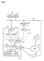
- FIG. 1 is an explanatory drawing showing the schematic structure of the storage system of the first embodiment.
- the storage system 100 of the first embodiment comprises a computer 10 and a storage device system 20 accessed by the computer 10.
- a client computer 30 and 31, a management server 50, and a service host 51 are connected via a network 40 or are directly connected to the storage system 100.
- the computer 10 and the storage device system 20 are stored in the same case, and this is identified as a file server from external computers. Also, because the computer 10 and the storage device system 20 are stored in the same case, writing and reading of files and generation of files are executed using common control commands between the computer 10 and the storage device system 20.
- the computer 10 of the first embodiment is connected to the client computers 30 and 31 via the network 40.
- the network 40 is a local area network (LAN) built using the Ethernet (registered trademark), and data transmission is executed using the TCP/IP protocol as the communication protocol.
- the client computers 30 and 31 are external computers that use the storage system 100, and request file write, read, and generation to the storage device system 20 via the computer 10 within the storage system 100.
- the computer 10 internally comprises a central processing unit (CPU) 11, memory 12, and a LAN interface 13.
- the CPU 11, the memory 12, and the LAN interface 13 are mutually connected via a bus.
- the CPU 11 is the operation processing device for executing various types of programs and modules stored in the memory 12.
- the memory 12 is a so-called internal storage device, and comprises both non-volatile memory for storing various modules and the like and volatile memory for temporarily storing the operation processing results.
- the LAN interface 13 is connected to the network 40, and executes sending and receiving of commands and data between the client computers 30 and 31 using the TCP/IP protocol.
- the storage device system 20 comprises the central processing unit (CPU) 21, the memory 22, the FC interface 23 and 26, a plurality of disk devices 24, a disk interface 25, and a LAN interface 27.
- the CPU 21 executes various control processes for the storage device system 20 by executing various programs and modules stored in the memory 22.
- the memory 22 is a so-called internal storage device, and comprises both non-volatile memory for storing various modules and the like and volatile memory for temporarily storing the operation processing results.
- the FC interface 23 is connected using optical fiber cable or copper wire, for example, and executes sending and receiving of commands and data between the computer 10 and the storage device system 20 using the fiber channel protocol.
- the disk device 24 is a disk array device made by RAID construction from a plurality of magnetic hard disk drives, and provides one or a plurality of storage areas, specifically, logical devices (LDEV) using the plurality of hard disk drives, or provides one or a plurality of logical devices by one hard disk drive. Access to each of the logical devices (also called logical units) is executed using the logical unit number (LUN) and the logical block address (LBA).
- LUN logical unit number
- LBA logical block address
- the CPU 21 is connected to the disk device 24 via the disk interface 25.
- the disk interface 25 converts the logical addresses transmitted from the CPU 21 to the logical block addresses, and access to each of the logical devices is realized by the CPU 21.
- a service host computer 51 is connected to the FC interface 26 via the optical fiber cable, or the service host computer 51 is connected via an SAN (Storage Area Network).
- the service host computer 51 executes work programs such as a database management system (DBMS), writes the processing results to the storage device system 20, or uses the information resources stored in the storage device system 20.
- DBMS database management system
- DBMS database management system
- the client computers 30 and 31 are terminal devices for inputting or outputting various types of data to the storage device system 20, for example, and may also comprise one unit or three or more units. Note that the client computers 30 and 31 may also be connected to the service host 51 via the network 40, and may be connected to the storage device system 20 via the application program that is implemented ins the service host 51.
- the management server 50 is a management computer for executing management on the storage system 100, for example, creation of volumes on the storage device system 20, allocation to the host, zoning, and setting of LUN masking.
- the management server 50 is connected to the LAN interface 27 of the storage device system 20 via the LAN interface 28 of the storage system 100, and executes sending and receiving of commands and data between the storage device system 20 using the TCP/IP protocol.
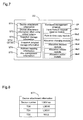
- FIG. 2 is an explanatory drawing conceptually showing the various programs and modules stored in the memory 12 of the computer 10 contained in the storage system of the first embodiment of FIG. 2.
- FIG. 3 is an explanatory drawing showing an example of the table for storing the snapshot management information.
- FIG. 4 is an explanatory drawing showing an example of the table for storing the directory device information.
- FIG. 5 is an explanatory drawing showing an example of the table for storing the device mount information.
- FIG. 6 is an explanatory drawing showing an example of the table for storing the device mount information.
- the operating system OS for realizing the backbone processes of the computer 10
- the storage device system management process program FP for operating on the operating system OS
- the snapshot management information table CT1 the device mount information table CT2, the directory device information table CT3, and the usable device information table CT4.
- the storage device system management program FP is a program for managing access to the storage device system 20, and contains several execution modules.
- the request receiving module Mc1 receives requests for access to the computer side logical device (directory) identified by the computer 10 from the client computers 30 and 31.
- the target device identification module Mc2 identifies the target device to be mounted in the computer side logical devices for which access is requested.
- the target device is the logical device that may be recognized as the device subject to access when the computer 10 accesses the storage device system 20, and is defined by the port ID and the LUN.
- the computer 10 is able to access the desired logical device corresponding to the computer side logical device via the target device that has the port role for the storage device system 20.
- the target device and the computer side logical device have a uniform relationship and the path is fixed, but with this embodiment, one or a plurality of computer side logical devices are dynamically allocated to one target device, so the path for the logical device changes.
- the target device may also be the plurality of physical ports comprised in the storage device system 20, or may also be the virtual port provided logically by the port provision module comprised by the storage device system 20.
- the mount decision module Mc3 determines whether the target device identified by the target device identification module Mc2 is already mounted in another computer side logical device. Specifically, as described previously, with this embodiment, a plurality of computer side logical devices may be allocated to the target device, so this determination is necessary.
- the mounting module Mc4 mounts the identified target device to the computer side requested logical device for which access is requested. As a result, the computer 10 is capable of accessing the logical device of the storage device system 20 corresponding to the computer side requested logical device via the target device.
- the mount action module Mc4 mounts the identified target device to the computer side requested logical device.
- the unmount action module Mc5 cancels the mounting of the target device to the computer side logical device.
- the computer 10 is not able to access the logical device of the storage device system 20 corresponding to the computer side requested logical device via the target device.
- the actual entity comprising the target device and the logical device is the storage device system 20, and at the computer 10, the process of mounting and unmounting the computer side target device on the computer side logical device (directory) realized by software is executed on the operating system (file system).
- attachment (allocation) or detachment (allocation release) of the target device and the logical device is executed corresponding to the mounting and unmounting of the identified target device for the computer side requested logical device for the computer 10.
- the target device (target device information) recognized on the operation system of the computer 10 is the target device Dev
- the actual target device for the storage device system 20 is the target device TD.
- the computer side storage area (storage area of computer) is called the directory
- the storage area of the storage device system 20 is called the logical device LDEV.
- the logical device LDEV is also called the logical unit LU.
- the Input/Output request reserve module Mc6 transmits to the storage device system 20 the command for requesting access to the logical device of the storage device system 20 corresponding to the computer side requested logical device.
- the commands contain information for identifying the logical device to be attached to the target device.
- the point in time copy request module Mc7 is the module for requesting a point in time copy, acquisition of so-called snapshot files, to the storage device system 20.
- the snapshot is technology for copying an identified volume (directory) at an identified point in time, or of acquiring the difference data in relation to the original volume and reproducing the volume for the identified point in time.
- the former is the mirroring type snapshot executed by copying an identified volume at an identified point in time to another volume
- the latter is the copy on write type snapshot executed by saving the information prior to changing for the changed part in relation to the original volume to another volume. In either case, it is possible to call an identified volume at an identified point in time (generation) from the client computers 30 and 31.
- the directory provision module Mc8 provides the computer side storage area (directory) corresponding to the storage areas (logical device) comprised by the storage device system 20. Specifically, identification and operation of the logical devices existing on the storage device system 20 side are made possible on the computer 10 side via the directory. This module function is provided using the file system for example.
- the snapshot management information table CT1 is described while referencing FIG. 3.
- the snapshot system comprises a pair consisting of a primary volume (main volume) of which a snapshot is taken and a volume for storing the snapshot (secondary volume). Therefore, the snapshot management information table CT1 contains the snapshot primary side information and the secondary information.
- the primary information has the primary directory information stored in it, and the secondary information contains the ID that indicates the snapshot generation, the stored directory information, and information indicating whether or not the snapshot is acquired, specifically, information indicating whether or not the snapshot file is stored.
- the directory device information table CT2 will be described while referencing FIG. 4.
- the directory device information table CT2 contains the information on the directory to mounting the target device Dev, the information for the target device Dev on which the directory is mounted, and the information of the logical device LDEV corresponding to the directory. Note that as will be described later, when using the copy on write type snapshot used by the virtual volume, the same logical device LDEV is allocated to the plurality of secondary directories. In this case, it is possible to determine whether or not the logical device LDEV is mounted by whether or not the mount device information is NULL (unmounted or not mounted). With the example in FIG.
- the target device Dev1 is mounted in the secondary directory (/mnt/ss/home_s1), and the logical device LDEV corresponding to the secondary directory (/mnt/ss/home_s1) is the LDEV1. Also, the target device Dev is not mounted on the secondary directory (/mnt/ss/home_s2), and the logical device corresponding to the secondary directory (/mnt/ss/home_s2) is the LDEV2.
- the device mount information table CT3 will be described while referencing FIG. 5.
- the device mount information table CT3 shows the directory that is currently mounted in the target device Dev. With the example in FIG. 5, the secondary directory (/mnt/ss/home_s1) is mounted in the target device Dev.
- the usable device information table CT4 will be described while referencing FIG. 6.
- the usable device information table CT4 is the table indicating the usable target devices Dev. With the example in FIG. 6, the primary directory (/mnt/home) is mounted in the target device Dev0, and the secondary directory (/mnt/ss/home+s1) is mounted in the target device Dev1.
- FIG. 7 is an explanatory drawing that conceptually shows the various types of programs and modules stored in the memory 22 of the storage device system 20 contained in the storage system of the first embodiment.
- FIG. 8 is an explanatory drawing showing an example of the table for storing the device attachment information.
- FIG. 9 is an explanatory drawing showing an example of the table for storing the device attachment information when the virtual volume is used.
- FIG. 10 is an explanatory drawing showing an example of the table for storing the snapshot management information.
- FIG. 11 is an explanatory drawing showing an example of the table for storing the snapshot detailed management information.
- FIG. 12 is an explanatory drawing showing an example of the table for storing the snapshot detailed management information.
- the memory 22 stores the command processing program CP for interpreting commands received from the computer 10 and executing the requested processes, the device attachment information table ST1, the device attachment information table ST2 when using the virtual volume, the snapshot management information ST3, the snapshot detailed management information ST31 and ST32, the address mapping information table ST4, and the file management information table ST5.
- the command management program CP is a program for acquiring snapshots for the storage device system 20, and for realizing the execution of access (read/write) to the requested logical device (snapshot file), and the command management program CP contains several execution modules.
- the Input/Output request reserve module Ms1 receives access requests from the computer 10.
- the allocation change module Ms3 allocates the logical device LDEV for which access is requested to the identified target device TD.
- the allocation change module Ms3 comprises three more modules, the allocation decision module Ms4, the allocation release module Ms5, and the allocation action module Ms6.
- the allocation decision module Ms4 determines whether the identified target device TD for which there has been a request for allocation of the logical device LDEV has already had another logical device LDEV allocated (attached). Specifically, as described above, in this embodiment, since a plurality of logical devices LDEV may be allocated to the target device TD, this determination is necessary.
- the allocation release module Ms5 cancels the allocation of the logical device LDEV to the identified target device TD. As a result, it is possible to allocate the logical device LDEV for which access is requested to the identified target device TD.
- the allocation action module Ms6 allocates the requested logical device LDEV for which access has been requested to the identified target device TD.
- the allocation and allocation release of the logical device LDEV to the target device TD is realized by the switching of the path to the logical device LDEV.
- the point in time copy module Ms2 is module for executing the acquisition of the so-called snapshot files for the storage device system 20. For the acquisition of snapshots, creation of the secondary volumes for the primary volumes, copying of the primary volume data to the secondary volume or saving of the data subject to updating for the primary volume to the secondary volume, and updating of the snapshot management information are executed.
- the device attachment information table ST1 will be described while referencing FIG. 8. Described in the device attachment information table ST1 is the logical device LDEV allocated (attached) to the target device TD. With the example in FIG. 8, the logical device LDEV0 is attached to the target device TD0, the logical device LDEV1 is attached to the target device TD1, and the logical device LDEV is not attached to the target device TD2.
- the device attachment information table ST2 when using the virtual volume is described while referencing FIG. 9.
- the virtual volume is used when using the copy on write type snapshot.
- the data before updating (difference data) of the data that is subject to updating (correction) for the primary volume is stored together with the information at the time of update in a storage pool formed by a plurality of logical devices.
- the computer 10 forms the virtual volume using a group of difference data from the identified time and thereafter, and attaches this to the corresponding logical device LDEV.
- the computer 10 uses the data stored in the current primary volume and the difference data group to create a snapshot file of the identified point in time.
- the device attachment information table ST2 stores the logical device for attaching the virtual volume (snapshot file), the information of the logical device LDEV for which the snapshot file primary volume is attached, and the snapshot ID.
- the snapshot is not acquired, and when the snapshot is acquired later and the logical device LDEV1 is shared by the snapshot ID 1 to 3, one of the values 1 to 3 is stored in the space for the LDEV1 snapshot ID.
- the snapshot management information table ST3 will be described while referencing FIG. 10. Contained in the snapshot management information table ST3 comprised by the storage device system 20 are the status indicating whether or not each of the logical devices LDEV is in a pair state with any of the other logical devices LDEV, the pair attribute indicating whether the logical device LDEV in the pair state is the primary or the secondary logical device, and the address of pair information for storing the pointer indicating the information of the pair logical device LDEV that is the subject. With the example in FIG.
- the logical devices LDEV0 and LDEV1 are in a paired state, with the logical device LDEV0 being the copy source primary logical device, and the logical device LDEV1 being the copy destination (snapshot file storage destination) secondary logical device.
- the status is simplex (state without creating a pair), and the pair attribute is NULL.
- the primary snapshot detailed management information table ST31 and the secondary snapshot detailed management information table ST4 which are indicated by the pointer contained in the subject pair information of the snapshot management information table ST3 will be described.
- the primary snapshot detailed management information table ST31 are the snapshot ID of the secondary logical device in a paired relationship with the primary logical device, the logical device number, and the acquisition status indicating whether or not the snapshot has already been acquired.
- the secondary snapshot detailed management information table ST32 is information of the primary logical device that is in a paired relationship with the secondary logical device.
- the primary logical device LDEV0 is registered in the secondary logical device LDEV1 as the pair logical device LDEV.
- the snapshot management information table ST3 logical device number, the primary snapshot management information table ST31 primary logical device number, and the secondary logical device number, as well as the secondary snapshot management information table ST32 primary logical device number and the secondary logical device number each indicate the virtual volume number.
- the address mapping information table ST4 stores the address mapping information that is the information for linking the virtual volume address and the actual address of the pool area that constitutes the virtual volume.
- the address mapping information is information used for managing the actual storage position of each data for pool areas for which specification using a volume number is not possible by managing using the address of each data for the virtual volume. Note that when the volume subject to access is an actual volume, it is possible to specify the storage position of the data using the volume number.
- the file management information table ST5 stores file management information for managing the directory in which files are stored. Note that this will be described in detail later.
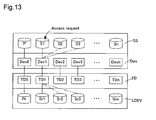
- FIG. 13 is an explanatory drawing showing the typical correlation between the snapshot file information SS and the target device information Dev recognized by the file system of the computer 10 and the target device TD and the logical device LDEV (snapshot file actual information) for the storage device system 20.
- FIG. 14 is a flow chart showing the processing routine executed for the process of accessing the mirroring type snapshot file.
- the primary volume file recognized by the client computer 30 (31) is represented as file P
- the snapshot files are represented as snapshot files S to Sn
- the actual primary volume file is represented as the file Pr
- the actual snapshot file is represented as the snapshot file Sr1 to Srn.
- the primary volume file P and the snapshot files S1 to Sn are identified by the directory SS
- the actual snapshot files Sr1 to Srn are identified by the logical device LDEV.
- the target device Dev0 is mounted on the primary volume file P.
- the snapshot files S1 to S3 which are the secondary volume files of the primary volume file may be exclusively mounted respectively in the target device Dev1.
- the storage device system 20 comprises a plurality of target devices TD, and a plurality of logical devices LDEV (actual snapshot files) are attached to one target device TD.
- the primary volume file Pr is attached to the target device TD0
- the plurality of actual snapshot files Sr1 to Sr3 are exclusively attached to the target device TD1.
- the target device TD1 is attached to the logical device LDEV1 that stored the actual snapshot file Sr1.
- the logical device LDEV is attached to the target device TD for the storage device system 20 so as to correspond to the mounting of the target device Dev to the directory SS for the computer 10.
- the flow chart shown in FIG. 14 is executed.
- the CPU 11 uses the snapshot management information table CT1 stored in the memory 12 and retrieves the directory SS in which the requested snapshot file Sn is stored (step SC100).
- the CPU 11 uses the usable device information table CT4 to retrieve the target device Dev used for accessing the retrieved directory (step SC110). Specifically, the usable target device Dev is retrieved (identified). With the example of the usable device information table CT4 shown in FIG. 6, the target device Dev1 may be used for the directory (/mnt/ss/home_s1). Following, with a specific example, the request directory will be (/mnt/ss/home_s1), and the retrieved target device Dev will be Dev1.
- the CPU 11 uses the directory device information table CT2 and determines whether or not the retrieved target device Dev is mounted in the requested directory (step SC120).
- a determination is made of whether or not the retrieved target device Dev is mounted in the request directory (step SC120: Yes), and even if the target device Dev is already mounted in the request directory, the requested snapshot file Sr is already attached to the target device TD corresponding to the storage device system 20 as well, so this processing routine ends.
- the client computers 30 and 31 are in a state capable of accessing the snapshot file S1.
- step SC120 determines that the retrieved target device Dev is not mounted in the request directory (step SC120: No)
- the CPU 11 determines whether or not the mount device information in the request directory for the directory device information table CT2 is NULL, and also whether or not the retrieved target device Dev is registered in the mount device information in another directory. For example, when the request directory is (/mnt/ss/home_s2), and the identified target device is Dev1, with the example in FIG.
- the target device Dev1 is mounted in the directory (/mnt/ss/home_s1), and the mount device information of the request directory (/mnt/ss/home_s2) is NULL, so the retrieved target device Dev is mounted in another directory.
- step SC130 When the CPU 11 determines that the retrieved target device Dev is mounted in another directory (step SC130: Yes), the retrieved target device information Dev is unmounted from the other directory (step SC140). In specific terms, the CPU 11 invalidates, in other words, nullifies, the mount device information of the other directory (/mnt/ss/home_s1) in which the retrieved target device Dev1 stored in the directory device information CT2 is mounted, and the directory information of the target device Dev1 for the device mount information table CT3.
- step SC140 is skipped, and the process moves to step SC150.
- the CPU 11 transmits to the storage device system 20 the access request containing the identification information for identifying the logical device LDEV to be attached to the retrieved target device Dev.
- the identification information the information of the logical device corresponding to the retrieved target device Dev retrieved for the directory device information table CT2 is used.
- information for identifying the logical device LDEV1 is sent.
- the CPU 21 of the storage device system 20 When the CPU 21 of the storage device system 20 receives an access request from the computer 10, the other logical device LDEV that is attached to the target device TD uniquely corresponding to the retrieved target device Dev is detached (SS100). In specific terms, the CPU 21 nullifies the LDEV that is attached to the retrieved target device TD in the device attachment information table ST1.
- the CPU 21 attaches the logical device identified by the identification information received from the computer 10 to the target device TD from which the logical device LDEV is detached (step SS110). In specific terms, the CPU 21 registers the LDEV1 to the LDEV that is attached to the concerned target device TD in the device attachment information table ST1.
- the CPU 21 transmits a detachment/attachment completion report to the computer 10 (SS12), and this processing routine ends.
- the CPU 11 of the computer 10 When the CPU 11 of the computer 10 receives the detachment/attachment completion report from the storage device system 20, the requested directory is mounted in the retrieved target device information Dev (step SC160), and this process routine ends.
- the CPU 11 registers the retrieved target device information Dev to the mount device information of the directory information in the directory device information table CT2, and registers the request directory in the directory information of the retrieved target device information Dev in the device mount information table CT3.
- the request directory is (/mmt/ss/home_s1)
- the retrieved target device information Dev1 is registered in the mount device information of the request directory (/mnt/ss/home_s2) in the directory device information table CT2
- the request directory (/mnt/ss/home_s2) is registered in the directory information of the retrieved target device information Dev in the device directory information table CT3.
- FIG. 15 is a flow chart showing the processing routine that is executed when acquiring the mirroring type snapshot file. Note that using FIG. 14 for description, a simple description is given regarding the same process as the steps in the process of accessing the snapshot files.
- the CPU 11 of the computer 10 for which a request is made to acquire snapshot files from the client computers 30 and 31 searches the request directory for storing the requested snapshot (step SC200) and retrieves the target device information Dev correlated to the request directory (step SC210).
- the CPU 11 uses the snapshot management information table CT1, searches directories indicating an acquisition state of not being acquired, and, for example, identifies the request directory in low to high sequence of the snapshot ID.
- the CPU 11 retrieves the target device Dev corresponding to the request directory from the usable device information table CT4, and identifies the corresponding logical device LDEV using the directory device information table CT2.
- the CPU 11 transmits to the storage device system 20 information of the identified logical device as well as the snapshot file acquisition request (step SC220).
- the CPU 21 of the storage device system 20 detaches the target device TD corresponding uniquely to the retrieved target device Dev from the other logical device LDEV (step SS200), and attaches the identified logical device LDEV to the target device TD for which the other logical device LDEV was detached (step SS210).
- the specific procedure was described with the description of SS100 and SS110 of FIG. 14.
- the CPU 21 creates a secondary volume of the primary volume in the identified logical device LDEV, and acquires the snapshot file (step SS220). In specific terms, a copy of the primary volume is generated for the identified logical device LDEV.
- the CPU 21 updates the snapshot management information table ST3 (step SS230), sends the normal completion report to the computer 20 (step SS240), and ends this processing routine.
- a specific description will be given regarding the procedure for updating the snapshot management information table ST3.
- the CPU 21, in the primary snapshot management information table ST31 registers the number of the logical device LDEV newly stored in the snapshot file to the logical device number of the new snapshot ID, and updates the acquisition status of the new snapshot ID to already acquired.
- the CPU 21, in the secondary snapshot management information table ST32 registers the logical device LDEV0 to the primary logical device of the logical device LDEV in which the snapshot file is newly stored.
- the target device Dev (TD) is mounted in the directory SS in which the requested snapshot file is stored, so it is possible to effectively use the target device Dev resources.
- the storage system 100 of the first embodiment it is possible to mount a plurality of directory SS on one target device Dev, so in contrast with conventional technology, it is not necessary to maintain the resources of the target device for each directory.
- the computer 10 may also request acquisition of the snapshot file to the storage device system 20 without identifying in advance the directory for storing a new snapshot file.
- the information of the logical device LDEV for which the snapshot file is created is received from the storage device system 20, and the various tables may be updated.
- the computer 10 and the storage device system 20 when a new snapshot file is created, if a rule is set for storing the snapshot files in the low to high sequence of the open logical devices LDEV and directories, it is possible not to execute the step SC200 or the step SC210 executed by the computer 10.
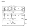
- FIG. 16 is an explanatory drawing typically showing the correlation of the snapshot file information SS and the target device information Dev recognized by the file system of the computer 10, the target device TD and the logical device LDEV for the storage device system 20, and the logical device LDEV and the snapshot data group stored in the storage pool.
- FIG. 17 is a flow chart showing the processing routine executed for the routine for accessing the copy on write type snapshot file.
- FIG. 18 is a flow chart showing the processing routine executed when acquiring the copy on write type snapshot file. Note that except for the point of the snapshot type being the copy on write type, this is the same as the mirroring type snapshot process described using FIG. 13 to FIG. 15, so for the same points, a detailed explanation is omitted, so the description will focus on the difference points.
- the primary volume file for the computer 10 recognized by the client computer 30 (31) is represented as the file P
- the snapshot files are represented as the snapshot files S to Sn.
- the actual primary volume file for the storage device system 20 is represented as the file Pr
- the update data (difference data) at an identified point in time is represented as Sd1 to Sd3
- the virtual volumes formed on the logical device LDEV during access to the snapshot file are represented as VS1 to VSn.
- the primary volume file P and the snapshot files S1 to Sn are identified by the directory SS
- the actual snapshot files Sd1 to Sdn are identified by the logical device LDEV.
- the target device Dev0 is mounted in the primary volume file P.
- the snapshot files S1 to S3 which are the secondary volume files of the primary volume file are respectively able to be mounted exclusively in the target device Dev1.
- the snapshot file S1 there is a request for access to the snapshot file S1, so only the directory of the snapshot file S1 is mounted in the target device Dev1.
- Each of the target devices Dev recognized by the computer 10 is uniquely correlated respectively to the target devices TD for the storage device system 20.
- the computer 10 uses the difference data of the primary volume file P to generate the snapshot file at an identified point in time and to provide this to the client computers 30 and 31.
- the storage device system 20 comprises a plurality of target devices TD, and a unique logical device LDEV (virtual volume VS) is attached to one target device TD.
- the update data (difference data) Sd1 to Sd3 at an identified point in time are stored in the storage pool Sp formed by the logical device LDEV.
- the storage device system 20 attaches the difference data Sr1 to the logical device LDEV, and forms the virtual volume VS1 on the logical device LDEV1.
- the plurality of difference data Sr1 to Sr3 are exclusively attached to the logical device LDEV.
- the difference data Sr is attached to the logical device LDEV for the storage device system 20 so as to correspond to the mounting of the target device Dev to the directory SS in the computer 10.
- the CPU 11 uses the snapshot management information table CT1 stored in the memory 12 to retrieve the directory SS in which the requested snapshot file Sn is stored (step SC300).
- the CPU 11 retrieves the target device Dev used for accessing the retrieved directory using the usable device information table CT4 (step SC310).
- the CPU 11 determines whether or not the target device Dev retrieved using the directory device information table CT2 is mounted in the requested directory (step SC320). Note that when using the virtual volume, for the directory device information table CT2 shown in FIG. 4, the same logical device LDEV is allocated to the plurality of directories SS.
- step SC320 Yes
- this processing routine ends.
- the client computers 30 and 31 are in a state for which it is possible to access the snapshot file S1.
- step SC320 determines that the retrieved target device Dev is not mounted in the request directory (step SC320: No)
- step SC330: Yes the CPU 11 determines that the retrieved target device Dev is mounted in another directory (step SC330: Yes)
- step SC340 the retrieved target device information Dev is unmounted from the other directory (step SC340).
- step SC330 When the CPU 11 determines that the retrieved target device Dev is not mounted in another directory (step SC330: No), step SC140 is skipped, and the process moves to step SC350.
- the CPU 11 transmits to the storage device system 20 the access request containing the identification information for identifying the difference data to be attached to the retrieved target device Dev.
- the target device Dev information, primary volume information, and snapshot ID are used for the identification information.
- the CPU 21 of the storage device system 20 When the CPU 21 of the storage device system 20 receives an access request from the computer 10, the CPU 21 converts the information of the target device TD uniquely corresponding to the retrieved target device Dev to the information of the corresponding logical device LDEV (step SS300). Specifically, the logical device LDEV uniquely corresponding to the target device TD is identified.
- the CPU 21 detaches the other snapshot data Sd that is attached to the concerned logical device corresponding to the retrieved target device TD (step SS310).
- the CPU 21 nullifies the primary logical device information of the concerned logical device and the snapshot ID in the device attachment information table ST2.
- the CPU 21 attaches the snapshot datan identified by the identification information received from the computer 10 to the logical device LDEV from which the other snapshot data Sd was detached (step SS320).
- the CPU 21 registers the received primary logical device information in the concerned logical device LDEV, and registers the received snapshot ID in the snapshot ID. For example, when the primary logical device is LDEV0 and the snapshot ID is 1, in the device attachment information table ST2, "LDEV0" is registered in the primary logical device of the concerned logical device LDEV, and "1" is registered in the snapshot ID.
- the CPU 21 transmits the detachment/attachment completion report to the computer 10 (SS330), and this processing routine ends.
- step SC360 the requested directory is mounted in the retrieved target device information Dev (step SC360), and this processing routine ends.
- the CPU 11 of the computer 10 for which a request was made to acquire the snapshot file from the client computers 30 and 31 searches the request directory for storing the requested snapshot (step SC400), and retrieves the target device information Dev correlated to the request directory (step SC410).
- the specific procedure was already described with the first embodiment.
- the CPU 11 transmits to the storage device system 20 the information of the identified logical device as well as a request for acquisition of the snapshot file (step SC420).
- the CPU 21 of the storage device system 20 When the CPU 21 of the storage device system 20 receives an access request from the computer 10, it converts the information of the target device TD uniquely corresponding to the retrieved target device Dev to the information corresponding logical device LDEV (step SS400). The CPU 21 detaches the other snapshot data Sd attached to the concerned logical device corresponding to the retrieved target device TD (step SS410).
- the CPU 21 creates the secondary volume for storing the difference data Sr in the storage pool Sp, and acquires the snapshot file (step SS420).
- the snapshot file In specific terms, one or a plurality of data copies before updating corresponding to the part that is updated (changed) in the primary volume is created and stored in the secondary volume.
- Information for identifying the snapshot generation is correlated to each data, and by using this identification information, it is possible to identify the difference data Sr relating to the identified generation.
- the CPU 21 updates the snapshot management information table ST3 (step SS430).
- the procedure for updating the snapshot management information table ST3 will be described specifically. Note that when using the virtual volume, the logical device number of the snapshot management information table ST3 and the snapshot detailed management information table ST31 and ST32 means the virtual volume number.
- the CPU 21 updates the status of the logical device LDEV for providing the virtual volume to "Pair" and updates the pair attribute to "Secondary" with attachment of the snapshot data.
- the CPU 21 registers the number of the logical device LDEV for providing the virtual volume to the logical device number of the new snapshot ID, and updates the acquisition status of the new snapshot ID to already acquired.
- the CPU 21 registers the logical device LDEV0 to the primary logical device of the logical device LDEV for providing the virtual volume.
- the CPU 21 attaches the snapshot datan identified by the identification information received from the computer 10 to the logical device LDEV form which the other snapshot data Sd was detached (step SS440), the CPU 21 sends a normal completion report to the computer 10 (step SS450), and this processing routine ends.
- the target device Dev is mounted on the directory SS in which the snapshot file requested from the client computers 30 and 31 is stored, so it is possible to effectively use the resources of the target device Dev.
- the storage device system 20 it is possible to exclusively allocate a plurality of difference data Sr to the logical device LDEV for providing the virtual volume, so in contrast to the conventional technology, it is not necessary to maintain the resources of the target device for each difference data. As a result, it is possible to reduce the volume of resources of the target device Dev and TD for allocation to the snapshot files for the overall storage system 100.
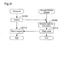
- the computer 10 by having information of whether the volume subject to access is an actual volume or a virtual volume, or by inquiring with the storage device system 20, may identify whether the volume subject to access is an actual volume or a virtual volume.
- FIG. 19 is an explanatory drawing typically showing the correlation between the snapshot file information and target device information recognized by the computer file system, the storage device system target device and logical device, and the primary side volume file data groups and the snapshot data groups stored in the logical device and the storage pool.
- FIG. 20 is an explanatory drawing showing an example of the table that stores the device attachment information for the variation example.
- FIG. 21 is an explanatory drawing showing an example of the table that stores the snapshot detailed management information for the variation example.
- the primary volume files for the computer 10 recognized by the client computer 30 (31) are represented as files P0 to P2, and the snapshot files are represented as snapshot files S1 to Sn.
- the virtual volume corresponding to the primary volume file is represented as VPr
- the virtual volumes formed on the logical device LDEV during access of the snapshot files are represented as VS1 to VSn.
- the actual data of the primary volume files for the storage pool Sp are represented as files Pd0 to Pd2
- the snapshot update data (differential data) at a specified point are represented as Sd1 to Sd3.
- the primary volume files P0 to 2 and the snapshot files S1 to Sn are specified by the directory SS, the actual data of the primary volume files are files Pd0 to Pd2, and the actual snapshot files Sd1 to Sdn are specified by the logical device LDEV.
- the primary volume files P0 to P2 are respectively mounted exclusively in the target device Dev0, and the snapshot files S1 to S3 that are secondary volume files of the primary volume files are respectively mounted exclusively in the target device Dev1.
- the snapshot of the primary volume file P0 is used as an example, so only the directory of the primary volume file P0 is mounted in the target device Dev0, and furthermore, there is a request for access to the snapshot file S1, so only the directory of the snapshot file S1 is mounted in the target device Dev1.
- the storage device system 20 is equipped with a plurality of target devices TD, and the virtual volumes VPr and VS (logical device LDEV) are uniquely attached to one target device TD.
- the actual data Pd0 to Pd2 of each primary volume file are stored in the storage pool Sp formed by the logical device LDEV.
- the storage device system 20 attaches the logical device LDEV0 to the primary volume file actual data Pd0, and forms the virtual volume VPr on the logical device LDEV0.
- the plurality of actual data Pd0 to Pd2 are exclusively attached to the logical device LDEV.
- the actual data Pd0 to 2 are attached to the logical device LDEV of the storage device system 20.
- the attachment of the actual data Pd0 to 2 to the logical device LDEV for the storage device system 20 is executed by the allocation switching module Ms3.
- the device attachment information table ST4 used when the primary volume file is a virtual volume is described while referring to FIG. 20.
- the device attachment information table ST4 stores the logical device for attaching the virtual volume (primary volume file), the primary volume file ID, and the snapshot ID.
- the identification information (ID) of the actual data attached to the logical device LDEV0 from among the actual data Pd0 to Pd2 for the storage pool Sp is stored in the logical device LDEV0.
- the primary volume file ID is NULL. Snapshots are not acquired with the example in FIG. 20, but snapshots are acquired later.
- the primary side snapshot detailed management information table ST4 used when the primary volume file is a virtual volume is described while referring to FIG. 21.
- the primary side snapshot detailed management information table ST4 contains the primary side logical device number, the snapshot ID of the secondary side logical device that has a pair relationship with the primary side logical device, the secondary side logical device number, and the acquisition status that indicates whether the snapshot has already been acquired.
- the upper level shows an example for which a virtual volume is not allocated to the primary volume file, the primary side logical device number is NULL, and snapshots have not been acquired.
- the lower level shows that a virtual volume is allocated to the primary volume file and LDEV10 has been registered for the primary side logical device number.
- the logical device LDEV1 for which the snapshot ID 1 is registered as the pair logical device LDEV.
- the primary side logical device number and the secondary side logical device number of the snapshot detailed management information table ST4 respectively indicate virtual volume numbers.
- FIG. 22 is an explanatory drawing showing the schematic structure of the storage system 100A related to other embodiments.
- the storage system 100A of FIG. 22 comprises a computer 10A and a storage device system 20A accessed by the computer 10A.
- the client computers 30 and 31 and the management server 50 are connected via the network 40 or directly connected to the storage system 100A.
- the commands used for the file system of the computer 10A and the commands used for the storage device system 20A, so it is necessary to define a special command and to send instructions from the computer 10A to the storage device system 20A.
- the computer 10A of FIG. 19 is connected to the client computers 30 and 31 via the network 40.
- the computer 10 internally comprises a central processing unit (CPU) 11A, a memory 12A, a LAN interface 13A, a storage interface 14A, and an FC interface 15A.
- the CPU 11A, the memory 12A, and each interface 13, 14, and 15 are mutually connected via a bus.
- the storage device system 20 comprises a central processing unit (CPU) 21A, a memory 22A, an FC interface 23A, a plurality of disk devices 24A, a disk interface 25A, a storage interface 26A, and a LAN interface 27A.
- CPU central processing unit
- the FC interfaces 15A and 23A are connected by an optic fiber cable or copper wire, for example, and commands and data are sent and received using a fiber channel protocol between the computer 10 and the storage device system 20.
- the management server 50 is connected to the storage device system 20A via the LAN interface 27A, and commands and data are sent and received.
- the disk device 24A is a disk array device formed by RAID construction by a plurality of magnetic hard disk drives, and one or a plurality of storage areas, specifically, logical devices (LDEV), are provided by a plurality of hard disk drives, or one or a plurality of logical devices is provided by one hard disk drive.
- LDEV logical devices
- the CPU 21A is connected to the disk device 24A via the disk interface 25A.
- the disk interface 25A converts the logic address transmitted from the CPU 21A to the logic block address, and access is realized to each logical device by the CPU 21A.
- the storage interfaces 14A and 26A are interfaces for exchanging special commands for indicating the detachment/attachment of the logical device LDEV to the target device TD between the computer 10A and the storage device system 20A.
- the special commands are preset standard read/write commands to the logical device LDEV (command device), and, for example, commands for indicating the detachment/attachment of the logical device LDEV to the target device TD and commands for indicating the acquisition of a snapshot are added.
- the computer 10A transmits special commands to the storage interface 26A of the storage device system 20 via the storage interface 14A.
- the storage interface 26A interprets the detachment/attachment command of the logical device LDEV to the added target device TD, executes the detachment/attachment process of the logical device LDEV to the target device TD, and gives instructions to execute the snapshot acquisition process.
- the storage system 100 of the first and second embodiments noted above described were examples of storing snapshot files, but it is also possible to try to reduce the target device Dev and TD resource volume and effectively utilize the storage system 100 in the same way for storage of typical files.
- the computer 10 side snapshot management information table CT1 and the storage device system 20 side snapshot management information table ST3 and the snapshot detailed management information tables ST31 and ST32 are not necessary.
- FIG. 23 is an explanatory drawing typically showing the correlation between the file information and target device information recognized by the computer file system, and the storage device system target device and logical device for the fourth embodiment.
- FIG. 24 is an explanatory drawing showing in detail the file management information table used for the fourth embodiment.
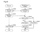
- FIG. 25 is a flow chart showing the processing routine executed for the process of accessing the files for the storage device system of the fourth embodiment.
- FIG. 26 is an explanatory drawing typically showing the correlation between the file information and target device information recognized by the computer file system and the file data groups of the storage device system.
- FIG. 27 is an explanatory drawing showing an example of a table that stores the device attachment information of the fifth embodiment.
- FIG. 28 is a flow chart showing the processing routine executed for the process of accessing the virtual volume file for the storage device system of the fifth embodiment.
- FIG. 29 is an explanatory drawing showing an example of the client identification table that the computer 10 has.
- each snapshot file S1 to Sn for the first embodiment be a directory (file) dedicated to each client computer, it is possible for the computer to mount the target device on a suitable directory, and for the storage device system 20 to attach the logical device LDEV to a suitable target device TD.
- the storage system 100 of the first embodiment each time the necessity arises for access to the snapshot file, mounting of the target device to the directory and attachment of the logical device LDEV to the target device TD are executed, so it is possible to process requests for access to a snapshot file as a request for access to a file from the client computer.
- the computer 10 and the storage device system 20 have the same tables except for tables relating to snapshots.
- the first resolution means (a) is described as the fourth embodiment while referring to FIG. 23 to FIG. 25.
- the files recognized by the client computer 30 (31) are represented as files F1 to Fn
- the actual file data stored in the storage device system 20 are represented as actual files L1 to Ln.
- Each file F is specified by a directory FG
- the actual files L1 to Ln are specified by the logical device LDEV.
- the files F1 to F3 can be respectively exclusively mounted in the target device Dev1.
- there is a request for access to the file F1 so the directory of the actual file L1 is mounted on the target device Dev1.
- Each target device Dev recognized by the computer 10 is respectively uniquely correlated to a target device TD of the storage device system 20.
- the storage device system 20 has a plurality of target devices TD, and a plurality of logical devices LDEV (actual files) are attached to one target device TD.
- a plurality of actual files L1 to L3 are exclusively attached to the target device TD1.
- the target device TD1 is attached to the logical device LDEV that stores the actual file L1.
- the logical device LDEV is attached to the target device TD for the storage device system 20.
- the file management information table ST5 is described while referring to FIG. 24.
- the file management information table ST5 are correlated and stored the computer side directory FG (file name) specified by the client computer 30 and the directory information (/mnt/ss/home fN) in which are stored actual files of the storage device system 20 side.
- the process of accessing the actual file for the first resolution means (a) is described while referring to FIG. 25.
- the CPU 11 of the computer 10 receives a request to access the file F from the client computer 30, the attachment process already described with FIG. 14 is executed together with the storage device system 20 (step SC500, SS500). Included in the access request is identification information for identifying the actual file L that corresponds to the computer side file F for which access has been requested.
- the CPU 11 of the computer 10 finds the Dev1 as the target device Dev for accessing the request directory F1, and sends the directory information that specifies the directory L1 to be attached to the found target device Dev1 to the storage device system 20.
- the CPU 21 of the storage device system 20 that received the directory information attaches the logical device LDEV (L1) that stores the requested actual file data to the target device TD1 correlated uniquely to the computer side target device Dev1.
- the target device Dev1 is mounted on the directory F1.
- the CPU 11 of the computer 10 sends a read/write request as the access request to the storage device system 20 (SC510).
- the storage device system 20 that has received the read/write request determines whether or not this is a read request (step SC510), and when it is a write request (step SC510: No), it executes the requested write process (step SS520), and this processing routine ends.
- step SC510 determines that this is a read request (step SC510: Yes)
- step SS530 executes the requested read process (step SS530), sends the read data to the computer 10 (step SS540), and this processing routine ends.
- the computer 10 receives the read data from the storage device system 20 (step SC520), sends it to the client computer 30, and this processing routine ends.
- the files for the computer 10 that are recognized by the client computer 30 (31) are represented as files F1 to Fn
- the virtual volumes formed on the logical device LDEV during access to the files F for the storage device system 20 are represented as VS1 to VSn
- the actual data of the files for the storage pool Sp are represented as Po1 to Po3.
- the files F1 to Fn are specified by the directory FG
- the actual data of the files Po1 to Po3 are specified by the logical device LDEV.
- the files F1 to F3 can respectively be exclusively mounted on the target device Dev1.
- there is a request to access the file F1 so only the directory of the file F1 is mounted on the target device Dev1.
- Each target device Dev recognized by the computer 10 is respectively uniquely correlated to a target device TD for the storage device system 20.
- the storage device system 20 is equipped with a plurality of target devices TD, and a unique logical device LDEV (virtual volume VS) is attached to one target device TD.
- the actual data of the file Po1 to Po3 are stored in the storage pool Sp formed by the logical device LDEV.
- the storage device system 20 attaches the actual data Po1 to the logical device LDEV1, for example, and forms the virtual volume VS1 on the logical device LDEV1.
- a plurality of actual data Po1 to Po3 are exclusively attached to the logical device LDEV.
- the actual data Po is attached to the logical device LDEV for the storage device system 20 so as to handle mounting of the logical device LDEV on the storage device system 20.
- an area correlating to the volume capacity amount of the corresponding file F is not secured in the storage pool from the start, but rather the storage area is increased according to updating of the file F.
- the storage device system 20 adds the address of the storage area added by the update to the management addresses.
- the device attachment information table ST2' used for this embodiment is described while referring to FIG. 27.
- the device attachment information table ST2' when using the virtual volume stores information of the logical device for attaching the virtual volume and of the actual data Po to be attached for forming the virtual volume.
- One of the actual data Po1 to Po3 is set to be attached, or not attached (NULL) to the logical device LDEV0, and one of actual data Po4 to Po6 is set to be attached, or not attached (NULL) to the logical device LDEV1.
- the process of accessing an actual file for the second means of resolving of (a) is described while referring to FIG. 28.
- the CPU 11 of the computer 10 receives a request to access any file F from the client computer 30, a read/write request for the virtual volume VS* corresponding to any file F is sent to the storage device system 20 (SC600).
- SC600 storage device system 20
- a case when a request is issued to access the file F1 is described as an example.
- the CPU 21 of the storage device system 20 determines whether the actual data Po1 of the file F1 is attached to the virtual volume VS1 corresponding to the file F1 for which access is requested (step SS600).
- step SS600 determines whether the access request is a read request (step SS610).
- step SS610 determines whether the access request is a read request (step SS610).
- the CPU 21 determines that this is not a read request, specifically, that it is a write request (step SS610: No)
- the write process is executed on the virtual volume VS1, and this processing routine ends.
- step SS610 When the CPU 21 determines that this is a read request (step SS610: Yes), read processing is executed on the virtual volume VS1 (step SS625). Note that for this embodiment, a data value "0" is recorded in the virtual volume FS depending on the format, and the read data value is the value of the data stored in the virtual volume VS, or is "0" when write is not executed after formatting.
- step SS600 when the CPU 21 determines that the actual data Po1 is not attached to the virtual volume VS1 (logical device LDEVO) (step SS600: No), it determines whether or not the access request is a read request (step SS630). When the CPU 21 determines that this is a read request (step SS630: Yes), ALLO is read and acquired as data (step SS640). Specifically, the subject actual data Po1 is not attached to the virtual volume VS1 and there is no data to be read, so the value "0" is returned from the read/write controller (disk controller).
- the read/write controller disk controller
- step SS630 When the CPU 21 determines that it is not a read request, specifically, that it is a write request (step SS630: No), the corresponding actual data Po1 is attached to the virtual volume VS1 (step SS645).
- the same as when it is a read request there is no virtual volume VS1 to which actual data Po1 is attached as the virtual volume VS to be written, so ALLO can be acquired. Specifically, for this embodiment, ALLO indicates that the execution results of the request process were unsuccessful.
- the CPU 21 sends the read data or the acquired data to the computer 10 (step SS650), and this process ends.
- the computer 10 receives the read data value or the value "0" from the storage device system 20 (step SC610), and this processing routine ends.
- the IP addresses for identifying each client computer and the target devices that may be used by each client computer are correlated.
- the computer 10 receives the access request from the client computer, it acquires the IP address of the client computer, and determines the target device to be accessed.
- the computer 10 gives notice to the client computer that access in the identified time is impossible, and transmits an interrupt access request to the storage device system 20 after an identified time has elapsed.
- the computer 10 transmits the interrupt access request to the storage device system 20 immediately, and provides access to the desired file to the client computer.
Landscapes
- Engineering & Computer Science (AREA)
- Theoretical Computer Science (AREA)
- Human Computer Interaction (AREA)
- Physics & Mathematics (AREA)
- General Engineering & Computer Science (AREA)
- General Physics & Mathematics (AREA)
- Information Retrieval, Db Structures And Fs Structures Therefor (AREA)
Priority Applications (1)
| Application Number | Priority Date | Filing Date | Title |
|---|---|---|---|
| EP20060251030 EP1705575B1 (de) | 2005-03-25 | 2006-02-27 | Speichersystem mit dynamischem Einhängen von Datenspeicherungsvorrichtungen. |
Applications Claiming Priority (4)
| Application Number | Priority Date | Filing Date | Title |
|---|---|---|---|
| JP2005087475 | 2005-03-25 | ||
| EP05256000.0A EP1705555B1 (de) | 2005-03-25 | 2005-09-27 | Speichersystem |
| JP2006015741A JP4987307B2 (ja) | 2005-03-25 | 2006-01-25 | ストレージシステム |
| EP20060251030 EP1705575B1 (de) | 2005-03-25 | 2006-02-27 | Speichersystem mit dynamischem Einhängen von Datenspeicherungsvorrichtungen. |
Publications (3)
| Publication Number | Publication Date |
|---|---|
| EP1705575A2 true EP1705575A2 (de) | 2006-09-27 |
| EP1705575A3 EP1705575A3 (de) | 2006-10-04 |
| EP1705575B1 EP1705575B1 (de) | 2013-12-25 |
Family
ID=36481244
Family Applications (1)
| Application Number | Title | Priority Date | Filing Date |
|---|---|---|---|
| EP20060251030 Ceased EP1705575B1 (de) | 2005-03-25 | 2006-02-27 | Speichersystem mit dynamischem Einhängen von Datenspeicherungsvorrichtungen. |
Country Status (1)
| Country | Link |
|---|---|
| EP (1) | EP1705575B1 (de) |
Cited By (1)
| Publication number | Priority date | Publication date | Assignee | Title |
|---|---|---|---|---|
| EP2637091A1 (de) * | 2012-03-07 | 2013-09-11 | Hitachi Ltd. | Verwaltungsschnittstelle zur Virtualisierung von Mehrfachspeicheruntersystemen |
Family Cites Families (3)
| Publication number | Priority date | Publication date | Assignee | Title |
|---|---|---|---|---|
| US6421711B1 (en) * | 1998-06-29 | 2002-07-16 | Emc Corporation | Virtual ports for data transferring of a data storage system |
| US7007043B2 (en) * | 2002-12-23 | 2006-02-28 | Storage Technology Corporation | Storage backup system that creates mountable representations of past contents of storage volumes |
| US7577806B2 (en) * | 2003-09-23 | 2009-08-18 | Symantec Operating Corporation | Systems and methods for time dependent data storage and recovery |
-
2006
- 2006-02-27 EP EP20060251030 patent/EP1705575B1/de not_active Ceased
Cited By (1)
| Publication number | Priority date | Publication date | Assignee | Title |
|---|---|---|---|---|
| EP2637091A1 (de) * | 2012-03-07 | 2013-09-11 | Hitachi Ltd. | Verwaltungsschnittstelle zur Virtualisierung von Mehrfachspeicheruntersystemen |
Also Published As
| Publication number | Publication date |
|---|---|
| EP1705575B1 (de) | 2013-12-25 |
| EP1705575A3 (de) | 2006-10-04 |
Similar Documents
| Publication | Publication Date | Title |
|---|---|---|
| US7793064B2 (en) | Storage system having a first computer, a second computer connected to the first computer via a network, and a storage device system that is accessed by the second computer | |
| US9152349B2 (en) | Automated information life-cycle management with thin provisioning | |
| US7757058B2 (en) | Storage system having dynamic volume allocation function | |
| US8775765B2 (en) | Computer system and control method therefor | |
| CN101276366B (zh) | 防止文件重复存储的计算机系统 | |
| US7506120B2 (en) | Data transfer virtualization system | |
| US9122415B2 (en) | Storage system using real data storage area dynamic allocation method | |
| US20040111485A1 (en) | Connecting device of storage device and computer system including the same connecting device | |
| US7343465B2 (en) | Storage system | |
| WO2004102391A1 (en) | Thin-provisioning with snapshot technology | |
| JPH06318168A (ja) | 階層データ記憶管理装置、方法およびそのネットワーク | |
| JP2012014286A (ja) | ストレージシステム、同システムにおけるデータバックアップ方法及びデータバックアッププログラム | |
| US20120265956A1 (en) | Storage subsystem, data migration method and computer system | |
| JP2006268534A (ja) | 記憶装置システムの制御技術 | |
| JP2007102760A (ja) | ストレージエリアネットワークにおけるボリュームの自動割り当て | |
| EP1705555B1 (de) | Speichersystem | |
| EP1705575B1 (de) | Speichersystem mit dynamischem Einhängen von Datenspeicherungsvorrichtungen. |
Legal Events
| Date | Code | Title | Description |
|---|---|---|---|
| PUAI | Public reference made under article 153(3) epc to a published international application that has entered the european phase |
Free format text: ORIGINAL CODE: 0009012 |
|
| PUAL | Search report despatched |
Free format text: ORIGINAL CODE: 0009013 |
|
| 17P | Request for examination filed |
Effective date: 20060316 |
|
| AK | Designated contracting states |
Kind code of ref document: A2 Designated state(s): AT BE BG CH CY CZ DE DK EE ES FI FR GB GR HU IE IS IT LI LT LU LV MC NL PL PT RO SE SI SK TR |
|
| AX | Request for extension of the european patent |
Extension state: AL BA HR MK YU |
|
| AK | Designated contracting states |
Kind code of ref document: A3 Designated state(s): AT BE BG CH CY CZ DE DK EE ES FI FR GB GR HU IE IS IT LI LT LU LV MC NL PL PT RO SE SI SK TR |
|
| AX | Request for extension of the european patent |
Extension state: AL BA HR MK YU |
|
| RIC1 | Information provided on ipc code assigned before grant |
Ipc: G06F 3/06 20060101AFI20060830BHEP |
|
| AKX | Designation fees paid |
Designated state(s): DE FR GB |
|
| RBV | Designated contracting states (corrected) |
Designated state(s): DE FR GB IE |
|
| 17Q | First examination report despatched |
Effective date: 20071030 |
|
| GRAP | Despatch of communication of intention to grant a patent |
Free format text: ORIGINAL CODE: EPIDOSNIGR1 |
|
| INTG | Intention to grant announced |
Effective date: 20130703 |
|
| GRAS | Grant fee paid |
Free format text: ORIGINAL CODE: EPIDOSNIGR3 |
|
| GRAA | (expected) grant |
Free format text: ORIGINAL CODE: 0009210 |
|
| RBV | Designated contracting states (corrected) |
Designated state(s): DE GB |
|
| AK | Designated contracting states |
Kind code of ref document: B1 Designated state(s): DE GB |
|
| REG | Reference to a national code |
Ref country code: GB Ref legal event code: FG4D |
|
| REG | Reference to a national code |
Ref country code: DE Ref legal event code: R096 Ref document number: 602006039751 Country of ref document: DE Effective date: 20140213 |
|
| REG | Reference to a national code |
Ref country code: DE Ref legal event code: R097 Ref document number: 602006039751 Country of ref document: DE |
|
| PLBE | No opposition filed within time limit |
Free format text: ORIGINAL CODE: 0009261 |
|
| STAA | Information on the status of an ep patent application or granted ep patent |
Free format text: STATUS: NO OPPOSITION FILED WITHIN TIME LIMIT |
|
| 26N | No opposition filed |
Effective date: 20140926 |
|
| REG | Reference to a national code |
Ref country code: DE Ref legal event code: R097 Ref document number: 602006039751 Country of ref document: DE Effective date: 20140926 |
|
| PGFP | Annual fee paid to national office [announced via postgrant information from national office to epo] |
Ref country code: DE Payment date: 20160223 Year of fee payment: 11 |
|
| PGFP | Annual fee paid to national office [announced via postgrant information from national office to epo] |
Ref country code: GB Payment date: 20160224 Year of fee payment: 11 |
|
| REG | Reference to a national code |
Ref country code: DE Ref legal event code: R119 Ref document number: 602006039751 Country of ref document: DE |
|
| GBPC | Gb: european patent ceased through non-payment of renewal fee |
Effective date: 20170227 |
|
| PG25 | Lapsed in a contracting state [announced via postgrant information from national office to epo] |
Ref country code: DE Free format text: LAPSE BECAUSE OF NON-PAYMENT OF DUE FEES Effective date: 20170901 |
|
| PG25 | Lapsed in a contracting state [announced via postgrant information from national office to epo] |
Ref country code: GB Free format text: LAPSE BECAUSE OF NON-PAYMENT OF DUE FEES Effective date: 20170227 |