EP1705495A2 - Procédé d'amélioration de la détection d'un objet - Google Patents
Procédé d'amélioration de la détection d'un objet Download PDFInfo
- Publication number
- EP1705495A2 EP1705495A2 EP06290404A EP06290404A EP1705495A2 EP 1705495 A2 EP1705495 A2 EP 1705495A2 EP 06290404 A EP06290404 A EP 06290404A EP 06290404 A EP06290404 A EP 06290404A EP 1705495 A2 EP1705495 A2 EP 1705495A2
- Authority
- EP
- European Patent Office
- Prior art keywords
- uncertainty
- cone
- obstacles
- field
- sensor
- Prior art date
- Legal status (The legal status is an assumption and is not a legal conclusion. Google has not performed a legal analysis and makes no representation as to the accuracy of the status listed.)
- Withdrawn
Links
Images
Classifications
-
- H—ELECTRICITY
- H02—GENERATION; CONVERSION OR DISTRIBUTION OF ELECTRIC POWER
- H02G—INSTALLATION OF ELECTRIC CABLES OR LINES, OR OF COMBINED OPTICAL AND ELECTRIC CABLES OR LINES
- H02G15/00—Cable fittings
- H02G15/02—Cable terminations
- H02G15/06—Cable terminating boxes, frames or other structures
- H02G15/064—Cable terminating boxes, frames or other structures with devices for relieving electrical stress
- H02G15/068—Cable terminating boxes, frames or other structures with devices for relieving electrical stress connected to the cable shield only
-
- G—PHYSICS
- G01—MEASURING; TESTING
- G01S—RADIO DIRECTION-FINDING; RADIO NAVIGATION; DETERMINING DISTANCE OR VELOCITY BY USE OF RADIO WAVES; LOCATING OR PRESENCE-DETECTING BY USE OF THE REFLECTION OR RERADIATION OF RADIO WAVES; ANALOGOUS ARRANGEMENTS USING OTHER WAVES
- G01S3/00—Direction-finders for determining the direction from which infrasonic, sonic, ultrasonic or electromagnetic waves, or particle emission, not having a directional significance, are being received
- G01S3/02—Direction-finders for determining the direction from which infrasonic, sonic, ultrasonic or electromagnetic waves, or particle emission, not having a directional significance, are being received using radio waves
- G01S3/04—Details
- G01S3/06—Means for increasing effective directivity, e.g. by combining signals having differently oriented directivity characteristics or by sharpening the envelope waveform of the signal derived from a rotating or oscillating beam antenna
-
- G—PHYSICS
- G01—MEASURING; TESTING
- G01S—RADIO DIRECTION-FINDING; RADIO NAVIGATION; DETERMINING DISTANCE OR VELOCITY BY USE OF RADIO WAVES; LOCATING OR PRESENCE-DETECTING BY USE OF THE REFLECTION OR RERADIATION OF RADIO WAVES; ANALOGOUS ARRANGEMENTS USING OTHER WAVES
- G01S3/00—Direction-finders for determining the direction from which infrasonic, sonic, ultrasonic or electromagnetic waves, or particle emission, not having a directional significance, are being received
- G01S3/78—Direction-finders for determining the direction from which infrasonic, sonic, ultrasonic or electromagnetic waves, or particle emission, not having a directional significance, are being received using electromagnetic waves other than radio waves
- G01S3/7803—Means for monitoring or calibrating
-
- G—PHYSICS
- G01—MEASURING; TESTING
- G01S—RADIO DIRECTION-FINDING; RADIO NAVIGATION; DETERMINING DISTANCE OR VELOCITY BY USE OF RADIO WAVES; LOCATING OR PRESENCE-DETECTING BY USE OF THE REFLECTION OR RERADIATION OF RADIO WAVES; ANALOGOUS ARRANGEMENTS USING OTHER WAVES
- G01S3/00—Direction-finders for determining the direction from which infrasonic, sonic, ultrasonic or electromagnetic waves, or particle emission, not having a directional significance, are being received
- G01S3/78—Direction-finders for determining the direction from which infrasonic, sonic, ultrasonic or electromagnetic waves, or particle emission, not having a directional significance, are being received using electromagnetic waves other than radio waves
- G01S3/781—Details
Definitions
- the technical field of the present invention is that of the detection of objects using an angular sensor.
- an object When an object moves in an evolution zone, it can either detect a threat or be detected. But the natural obstacles in the area may partially or totally obscure the object due to the movements of one or the other.
- an angular sensor DAL laser warning detector, DDM missile departure detection, directional antenna, etc.
- detects an object it provides an operator with a half-cone representing the uncertainty zone where it is located. object. This zone should be as small as possible in order to increase the probabilities of detection of the target or the threat and to present the operator with an image of the threat without having to make a search or adjustments.
- the object of the present invention is to provide a method and a device for reducing the uncertainty of location of an object and a device for implementing this method.
- the subject of the invention is therefore a method for improving the detection of an object moving in an observation field of an angular sensor, a sensor having a location uncertainty cone having a direction A, characterized in that that the obstacles present in the cone of uncertainty are determined, the solid field angles covered by these obstacles are evaluated in the cone of uncertainty, a cone of uncertainty is calculated by removing from the cone of initial uncertainty the cones of uncertainty. field covered not these obstacles.
- the obstacles present in the cone of uncertainty are determined using a cartographic database coupled to means for calculating the direction A and the solid angle of the cone of uncertainty.
- the obstacles present in the cone of uncertainty are determined by means of an obstacle library possibly coupled to a camera and / or a range finder and accessible via a Human Machine Interface.
- At least two angular sensors located at a distance from one another are used and the uncertainty zones of these two sensors are combined to reduce the effective area of uncertainty.
- the invention also relates to a device for implementing the method of improving the detection of an object, characterized in that it comprises an angular sensor disposed at a distance from an object moving in a field of observation said sensor, the latter having a cone or solid angle oriented in a direction A, a means for determining the obstacles present in the cone of uncertainty and for calculating the cones or solid angles of this field covered by these obstacles in the cone of uncertainty, and a calculating means ensuring the determination of a cone or solid angle of uncertainty reduced by the subtraction of the cone of initial uncertainty field cones covered by the obstacles.
- the device comprises two sensors defining two uncertainty angles and means for coupling the values obtained in order to determine the uncertainty angle.
- the angular sensor is a laser detection sensor.
- a first advantage of the method and the device according to the invention lies in a maximum exploitation of the information collected in the field or provided by a cartographic database in order to limit the uncertainties.
- Another advantage is that the reduction of the uncertainty angle can be fully automated.
- Yet another advantage is that the uncertainty angle is determined in real time to enable decision making.
- Yet another advantage of the invention is to facilitate the viewing of a threat without having to perform a search.
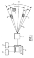
- FIG. 1 represents an exemplary embodiment of the invention.
- a sensor 1 providing an operator disposed near or remote an observation field 3 of a distant object 2.
- This field is here represented in a horizontal plane as an uncertainty angle 4.
- the field is in fact a globally conical uncertainty zone.
- solid angle for the angle of uncertainty, ie volume defined in space by a cone.
- This conical field has an axis oriented in a direction A which depends on the orientation which is given to the sensor for example by motorization means (not shown).
- the direction A is defined relative to a reference (for example linked to a vehicle bearing the sensor) by site and bearing angles.
- the sensor 1 is generally a laser warning detector (DAL), a missile departure detector (DDM), a directional antenna, an infrared camera, a camera in the visible spectrum. This detector is able to detect a laser flash or any other threat.
- DAL laser warning detector
- DDM missile departure detector
- This detector is able to detect a laser flash or any other threat.
- obstacles 5 and 6 are present and mask the observation of the sensor 1 by defining solid presence angles 7 and 8. These obstacles can be of different types: hill, dense forest, constructions. It is desirable operationally to take into account the presence of obstacles in the field of view 3 to reduce the solid angle of theoretical uncertainty 4 of the sensor and thus improve accuracy of the location of the object.
- a calculation means 10 makes it possible to subtract these solid angles 7 and 8 from the presence of obstacles and thus to provide a solid angle of uncertainty. corresponding to the reduced field in which the object must be to be detected.
- a commercial calculator 12 can be implemented to perform this function.
- the calculator 12 uses the cartographic data of the observed area (data which is contained in a cartographic database) and it also knows the observation direction A of the detector 1 (supplied by the detector positioning means) and the opening of the uncertainty cone 4 of this detector. It is therefore able to automatically determine which obstacles present in the cartographic base are in the cone of uncertainty (obstacles such as forest, hill, ). It will therefore calculate a first reduced field 9 by eliminating the solid angles 7 and 8 of the field of view.
- the computer 12 will provide the user through a suitable human machine interface (a screen for example) a visualization of the terrain on which will be superimposed the reduced uncertainty field 9 thus calculated.
- the calculator will offer the possibility to the user then to introduce other obstacles that were absent from the cartographic base but are in the field (for example walls or buildings). These obstacles will be introduced for example from a library accessible via drop-down menus. The dimensions of these obstacles will be introduced manually by the operator or calculated using a measuring means such as a camera coupled to a rangefinder. After their introduction, they will appear on the interface of the user and the calculator will automatically determine the value of the new uncertainty field reduced 9.
- the information obtained is directed to the computer 12 which will provide an operator with information on the presence of an enemy in a small field to better understand the threat and make an appropriate decision.
Landscapes
- Physics & Mathematics (AREA)
- Engineering & Computer Science (AREA)
- General Physics & Mathematics (AREA)
- Radar, Positioning & Navigation (AREA)
- Remote Sensing (AREA)
- Electromagnetism (AREA)
- Optical Radar Systems And Details Thereof (AREA)
- Radar Systems Or Details Thereof (AREA)
- Geophysics And Detection Of Objects (AREA)
Abstract
Description
- Le secteur technique de la présente invention est celui de la détection des objets à l'aide d'un capteur angulaire.
- Lorsqu'un objet se déplace dans une zone d'évolution, il peut soit détecter une menace soit être détecté. Mais les obstacles naturels présents dans la zone peuvent masquer partiellement ou totalement l'objet en raison des déplacements de l'un ou de l'autre. Actuellement, lorsqu'un capteur angulaire (détecteur d'alerte laser DAL, détection de départ missile DDM, antenne directive, etc) détecte un objet, il fournit à un opérateur un demi-cône représentant la zone d'incertitude où se trouve l'objet. Cette zone doit être la plus réduite possible afin d'augmenter les probabilités de détection de la cible ou de la menace et de présenter à l'opérateur une image de la menace sans qu'il ait besoin de faire une recherche ou des réglages.
- Le but de la présente invention est de proposer un procédé et un dispositif pour réduire l'incertitude de localisation d'un objet et un dispositif de mise en oeuvre de ce procédé.
- L'invention a donc pour objet un procédé d'amélioration de la détection d'un objet évoluant dans un champ d'observation d'un capteur angulaire, capteur présentant un cône d'incertitude de localisation ayant une direction A, procédé caractérisé en ce qu'on détermine les obstacles présents dans le cône d'incertitude, on évalue les angles solides de champ couverts ces obstacles dans le cône d'incertitude, on calcule un cône d'incertitude réduit en retranchant du cône d'incertitude initial les cônes de champ couverts pas ces obstacles.
- Selon une caractéristique de l'invention, on détermine les obstacles présents dans le cône d'incertitude à l'aide d'une base de données cartographiques couplée à un moyen de calcul de la direction A et de l'angle solide du cône d'incertitude.
- Selon une autre caractéristique de l'invention, on détermine les obstacles présents dans le cône d'incertitude à l'aide d'une bibliothèque d'obstacles couplée éventuellement à une caméra et/ou un télémètre et accessible via une interface homme machine.
- Selon encore une autre caractéristique de l'invention, on met en oeuvre au moins deux capteurs angulaires situés à distance l'un de l'autre et on combine les zones d'incertitude de ces deux capteurs pour réduire la zone d'incertitude effective.
- L'invention concerne également un dispositif pour la mise en oeuvre du procédé de d'amélioration de la détection d'un objet, caractérisé en ce qu'il comprend un capteur angulaire disposé à distance d'un objet évoluant dans un champ d'observation dudit capteur, ce dernier présentant un cône ou angle solide orienté suivant une direction A, un moyen pour déterminer les obstacles présents dans le cône d'incertitude et pour calculer les cônes ou angles solides de ce champ couverts par ces obstacles dans le cône d'incertitude, et un moyen de calcul assurant la détermination d'un cône ou angle solide d'incertitude réduit par la soustraction du cône d'incertitude initial des cônes de champ couverts par les obstacles.
- Selon une caractéristique, le dispositif comprend deux capteurs délimitant deux angles d'incertitude et un moyen pour coupler les valeurs obtenues afin de déterminer l'angle d'incertitude.
- Selon encore une autre caractéristique, le capteur angulaire est un capteur de détection laser.
- Un tout premier avantage du procédé et du dispositif selon l'invention réside dans une exploitation maximale des informations collectées sur le terrain ou bien fournies par une base de données cartographiques afin de limiter les incertitudes.
- Un autre avantage réside dans le fait que la réduction de l'angle d'incertitude peut être entièrement automatisée.
- Un autre avantage encore réside dans le fait que l'angle d'incertitude est déterminé en temps réel pour permettre la prise de décision.
- Un autre avantage encore de l'invention est de faciliter la visualisation d'une menace sans avoir à effectuer une recherche.
- D'autres caractéristiques, détails et avantages de l'invention ressortiront plus clairement de la description donnée ci-après à titre indicatif en relation avec un dessin sur lequel la figure 1 représente un exemple de réalisation de l'invention.
- Sur la figure 1, on a représenté un capteur 1 fournissant à un opérateur disposé à proximité ou éloigné un champ d'observation 3 d'un objet 2 éloigné. Ce champ est ici représenté dans un plan horizontal comme un angle d'incertitude 4. Dans l'espace, le champ est en fait une zone d'incertitude globalement conique. Par la suite et dans la description, on parlera d'angle solide pour l'angle d'incertitude, c'est à dire de volume délimité dans l'espace par un cône. La valeur de l'angle solide d'ouverture de la zone dépend des caractéristiques physiques du capteur (données du constructeur). Par ailleurs, ce champ conique a un axe orienté suivant une direction A qui dépend de l'orientation qui est donnée au capteur par exemple par des moyens de motorisation (non représentés). La direction A est définie par rapport à un repère (par exemple lié à un véhicule portant le capteur) par des angles de site et de gisement.
- Le capteur 1 est généralement un détecteur d'alerte laser (DAL), un détecteur de départ missile (DDM), une antenne directive, une caméra infra rouge, une caméra dans le spectre visible. Ce détecteur est apte à détecter un flash laser ou toute autre menace. Dans le champ d'observation, des obstacles 5 et 6 sont présents et masquent l'observation du capteur 1 en définissant des angles solides de présence 7 et 8. Ces obstacles peuvent être de différents types : colline, forêt dense, constructions. Il est souhaitable opérationnellement de tenir compte de la présence d'obstacles situés dans le champ d'observation 3 pour réduire l'angle solide d'incertitude théorique 4 du capteur et améliorer ainsi précision de la localisation de l'objet.
- Conformément à l'invention, un moyen de calcul 10 permet de soustraire ces angles 7 et 8 solides de présence d'obstacles et ainsi fournir un angle solide d'incertitude 9 correspondant au champ réduit dans lequel l'objet doit se trouver pour être détecté. Un calculateur du commerce 12 peut être mis en oeuvre pour réaliser cette fonction.
- En raison du fait que l'objet 2 et le détecteur 1 sont éloignés l'un de l'autre, les obstacles ne sont pas connus et leur présence et leur position doivent être introduites dans le champ d'observation. Un opérateur réalise cette introduction à l'aide d'un système 11, un système de cartographie ou une caméra par exemple, en introduisant la conformation du champ d'observation ce qui permet de visualiser tous les obstacles pouvant se présenter entre le capteur et l'objet. Le calculateur 12 utilise les données cartographiques de la zone observée (données qui sont contenues dans une base de données cartographiques) et il connaît aussi la direction d'observation A du détecteur 1 (fournie par le moyen de positionnement du détecteur) et l'ouverture du cône d'incertitude 4 de ce détecteur. Il est donc capable de déterminer automatiquement quels obstacles présents dans la base cartographique se trouvent dans le cône d'incertitude (obstacles tels que forêt, colline,...). Il va donc calculer un premier champ réduit 9 en éliminant les angles solides 7 et 8 du champ d'observation.
- Le calculateur 12 fournira à l'utilisateur par le biais d'une interface homme machine appropriée (un écran par exemple) une visualisation du terrain sur laquelle sera superposé le champ d'incertitude réduit 9 ainsi calculé. Conformément à une autre caractéristique de l'invention, le calculateur offrira la possibilité à l'utilisateur d'introduire alors d'autres obstacles qui étaient absents de la base cartographique mais se trouvent sur le terrain (par exemple des murs ou des bâtiments). Ces obstacles seront introduits par exemple à partir d'une bibliothèque accessible via des menus déroulants. Les dimensions de ces obstacles seront introduites manuellement par l'opérateur ou calculées grâce à un moyen de mesure tel une caméra couplée à un télémètre. Après leur introduction, ils apparaîtront donc sur l'interface de l'utilisateur et le calculateur déterminera automatiquement la valeur du nouveau champ d'incertitude réduit 9.
- On a noté précédemment que lorsqu'on mentionne dans la présente description un secteur angulaire ou un angle, on parle en fait d'angle solide, c'est à dire de volume délimité dans l'espace par un cône. Il est bien connu que le capteur 1 fournit une information suivant un volume sous forme d'un cône dont le sommet est situé au niveau du capteur. C'est dans ce cône que les obstacles sont repérés, également sous la forme d'angles solides.
- Les informations obtenues sont dirigées vers le calculateur 12 qui va permettre de fournir à un opérateur des informations sur la présence d'un ennemi dans un champ réduit pour mieux appréhender la menace et prendre une décision adéquate.
- Si on couple la détection par deux capteurs séparés l'un de l'autre, on voit qu'on réduit dans de fortes proportions par recoupement la zone d'incertitude.
- Il est possible de coupler les informations de détection fournies par deux capteurs séparés l'un de l'autre. Il est évident que si un objet est ainsi détecté par deux capteurs, il se trouve dans une zone qui est l'intersection des angles solides ou des champs d'incertitude de chaque capteur. Un tel couplage est classique. Il peut être associé au moyen de réduction d'incertitude proposé par l'invention. Chaque capteur a ainsi un champ d'incertitude qui est réduit grâce à l'invention, et l'objet se trouve donc dans une zone de détection qui est l'intersection de deux zones réduites.
Claims (7)
- Procédé d'amélioration de la détection d'un objet (2) évoluant dans un champ d'observation (3) d'un capteur angulaire (1), capteur présentant un cône d'incertitude de localisation ayant une direction A, procédé caractérisé en ce qu'on détermine les obstacles présents dans le cône d'incertitude, on évalue les angles solides de champ (7, 8) couverts ces obstacles dans le cône d'incertitude, on calcule un cône d'incertitude réduit (9) en retranchant du cône d'incertitude initial (4) les cônes de champ (7, 8) couverts pas ces obstacles.
- Procédé d'amélioration de la détection selon la revendication 1, caractérisé en ce qu'on détermine les obstacles présents dans le cône d'incertitude à l'aide d'une base de données cartographiques couplée à un moyen de calcul de la direction A et de l'angle solide du cône d'incertitude.
- Procédé d'amélioration de détection selon la revendication 1, caractérisé en ce qu'on détermine les obstacles (5, 6) présents dans le cône d'incertitude à l'aide d'une bibliothèque d'obstacles couplée éventuellement à une caméra et/ou un télémètre et accessible via une interface homme machine.
- Procédé d'amélioration de détection selon l'une quelconque des revendications précédentes, caractérisé en ce qu'on met en oeuvre au moins deux capteurs angulaires situés à distance l'un de l'autre et on combine les zones d'incertitude de ces deux capteurs pour réduire la zone d'incertitude effective.
- Dispositif pour la mise en oeuvre du procédé selon la revendication 1, caractérisé en ce qu'il comprend un capteur angulaire (1) disposé à distance d'un objet (2) évoluant dans un champ d'observation (3) dudit capteur, ce dernier présentant un cône ou angle solide orienté suivant une direction A, un moyen pour déterminer les obstacles présents dans le cône d'incertitude et pour calculer les cônes ou angles solides de ce champ (7, 8) couverts par ces obstacles dans le cône d'incertitude, et un moyen de calcul assurant la détermination d'un cône ou angle solide d'incertitude réduit (9) par la soustraction du cône d'incertitude initial (4) des cônes de champ (7, 8) couverts par les obstacles.
- Dispositif selon la revendication 4, caractérisé en ce qu'il comprend deux capteurs délimitant deux angles d'incertitude et un moyen pour coupler les valeurs obtenues afin de déterminer l'angle d'incertitude.
- Dispositif selon la revendication 5 ou 6, caractérisé en ce que le capteur angulaire (1) est un capteur de détection laser.
Applications Claiming Priority (1)
| Application Number | Priority Date | Filing Date | Title |
|---|---|---|---|
| FR0502763A FR2883381B1 (fr) | 2005-03-21 | 2005-03-21 | Procede d'amelioration de la detection d'un objet |
Publications (2)
| Publication Number | Publication Date |
|---|---|
| EP1705495A2 true EP1705495A2 (fr) | 2006-09-27 |
| EP1705495A3 EP1705495A3 (fr) | 2007-08-15 |
Family
ID=35240934
Family Applications (1)
| Application Number | Title | Priority Date | Filing Date |
|---|---|---|---|
| EP06290404A Withdrawn EP1705495A3 (fr) | 2005-03-21 | 2006-03-13 | Procédé d'amélioration de la détection d'un objet |
Country Status (2)
| Country | Link |
|---|---|
| EP (1) | EP1705495A3 (fr) |
| FR (1) | FR2883381B1 (fr) |
Cited By (1)
| Publication number | Priority date | Publication date | Assignee | Title |
|---|---|---|---|---|
| CN109660705A (zh) * | 2018-12-04 | 2019-04-19 | 浙江大华技术股份有限公司 | 一种智能球形摄像机及图像抓拍方法 |
Citations (2)
| Publication number | Priority date | Publication date | Assignee | Title |
|---|---|---|---|---|
| GB2307808A (en) | 1979-04-27 | 1997-06-04 | British Aerospace | Surveillance apparatus |
| US20040164902A1 (en) | 2003-02-24 | 2004-08-26 | Lars Karlsson | Direction finding method and system using probabilistic mapping |
Family Cites Families (1)
| Publication number | Priority date | Publication date | Assignee | Title |
|---|---|---|---|---|
| JPH0483285A (ja) * | 1990-07-26 | 1992-03-17 | Nec Home Electron Ltd | 車載用航法装置 |
-
2005
- 2005-03-21 FR FR0502763A patent/FR2883381B1/fr not_active Expired - Fee Related
-
2006
- 2006-03-13 EP EP06290404A patent/EP1705495A3/fr not_active Withdrawn
Patent Citations (2)
| Publication number | Priority date | Publication date | Assignee | Title |
|---|---|---|---|---|
| GB2307808A (en) | 1979-04-27 | 1997-06-04 | British Aerospace | Surveillance apparatus |
| US20040164902A1 (en) | 2003-02-24 | 2004-08-26 | Lars Karlsson | Direction finding method and system using probabilistic mapping |
Cited By (2)
| Publication number | Priority date | Publication date | Assignee | Title |
|---|---|---|---|---|
| CN109660705A (zh) * | 2018-12-04 | 2019-04-19 | 浙江大华技术股份有限公司 | 一种智能球形摄像机及图像抓拍方法 |
| CN109660705B (zh) * | 2018-12-04 | 2021-02-05 | 浙江大华技术股份有限公司 | 一种智能球形摄像机及图像抓拍方法 |
Also Published As
| Publication number | Publication date |
|---|---|
| FR2883381A1 (fr) | 2006-09-22 |
| EP1705495A3 (fr) | 2007-08-15 |
| FR2883381B1 (fr) | 2007-06-01 |
Similar Documents
| Publication | Publication Date | Title |
|---|---|---|
| Kim et al. | Firefighting robot stereo infrared vision and radar sensor fusion for imaging through smoke | |
| EP2333481B1 (fr) | Système optronique et procédé d'élaboration d'images en trois dimensions dédiés à l'identification | |
| Nurminen et al. | Performance of dense digital surface models based on image matching in the estimation of plot-level forest variables | |
| US9175975B2 (en) | Systems and methods for navigation | |
| JP5438263B2 (ja) | レーダ画像処理装置及びレーダ画像処理方法 | |
| CN104049259B (zh) | 基于虚拟仪器的激光雷达三维成像系统 | |
| Teizer | 3D range imaging camera sensing for active safety in construction | |
| EP1870789A1 (fr) | Système de détection d'obstacles au voisinage d'un point de poser | |
| CA2573320A1 (fr) | Systeme de detection des changements d'images geospatiales, et methodes associees | |
| FR2997046A1 (fr) | Systeme d'assistance de conduite et son procede de gestion | |
| EP1726973A1 (fr) | Procédé et dispositif d'aide au pilotage d'un aéronef à basse altitude | |
| FR2805350A1 (fr) | Equipement de telemetrie pour la cartographie bi- ou tri-dimensionnelle d'un volume | |
| CN107894284A (zh) | 一种结合探测效能的红外相机波段比较方法 | |
| CN104050473A (zh) | 一种基于矩形邻域分析的道路数据提取方法 | |
| EP2043044B1 (fr) | Procédé et dispositif d'assistance au parcage d'un véhicule automobile | |
| CN105866792B (zh) | 一种星载激光雷达树高提取方法 | |
| Rankin et al. | Passive sensor evaluation for unmanned ground vehicle mud detection | |
| FR2975484A1 (fr) | Procede de determination a distance d'un azimut absolu d'un point cible | |
| EP2407953B1 (fr) | Procédé d'aide au pilotage amélioré pour aéronef | |
| FR2953300B1 (fr) | Procede de detection par telemetrie d'au moins un objet filiforme suspendu se trouvant dans le champ de detection d'un telemetre embarque a bord d'un vehicule | |
| FR2883381A1 (fr) | Procede d'amelioration de la detection d'un objet | |
| JP3012927B1 (ja) | マルチスペクトル画像処理を用いた目標抽出装置 | |
| KR20190072791A (ko) | 장애물에 가려진 표적을 사격하는 원격 화기 제어 장치 | |
| FR2910680A1 (fr) | Procede et systeme de traitement et de visualisation d'images de l'environnement d'un aeronef | |
| WO2009053395A2 (fr) | Systeme de mesure d'une grandeur physique et de representation cartographique de ces mesures |
Legal Events
| Date | Code | Title | Description |
|---|---|---|---|
| PUAI | Public reference made under article 153(3) epc to a published international application that has entered the european phase |
Free format text: ORIGINAL CODE: 0009012 |
|
| AK | Designated contracting states |
Kind code of ref document: A2 Designated state(s): AT BE BG CH CY CZ DE DK EE ES FI FR GB GR HU IE IS IT LI LT LU LV MC NL PL PT RO SE SI SK TR |
|
| AX | Request for extension of the european patent |
Extension state: AL BA HR MK YU |
|
| RAP1 | Party data changed (applicant data changed or rights of an application transferred) |
Owner name: NEXTER SYSTEMS |
|
| PUAL | Search report despatched |
Free format text: ORIGINAL CODE: 0009013 |
|
| AK | Designated contracting states |
Kind code of ref document: A3 Designated state(s): AT BE BG CH CY CZ DE DK EE ES FI FR GB GR HU IE IS IT LI LT LU LV MC NL PL PT RO SE SI SK TR |
|
| AX | Request for extension of the european patent |
Extension state: AL BA HR MK YU |
|
| RIC1 | Information provided on ipc code assigned before grant |
Ipc: G01S 3/781 20060101ALI20070712BHEP Ipc: G01S 3/78 20060101ALI20070712BHEP Ipc: G01S 3/06 20060101AFI20060705BHEP |
|
| 17P | Request for examination filed |
Effective date: 20080125 |
|
| D17P | Request for examination filed (deleted) | ||
| 17Q | First examination report despatched |
Effective date: 20080222 |
|
| AKX | Designation fees paid |
Designated state(s): AT BE BG CH CY CZ DE DK EE ES FI FR GB GR HU IE IS IT LI LT LU LV MC NL PL PT RO SE SI SK TR |
|
| R17P | Request for examination filed (corrected) |
Effective date: 20080125 |
|
| GRAP | Despatch of communication of intention to grant a patent |
Free format text: ORIGINAL CODE: EPIDOSNIGR1 |
|
| STAA | Information on the status of an ep patent application or granted ep patent |
Free format text: STATUS: THE APPLICATION HAS BEEN WITHDRAWN |
|
| 18W | Application withdrawn |
Effective date: 20090220 |