EP1705409A1 - Butterfly outflow valve - Google Patents
Butterfly outflow valve Download PDFInfo
- Publication number
- EP1705409A1 EP1705409A1 EP20060251495 EP06251495A EP1705409A1 EP 1705409 A1 EP1705409 A1 EP 1705409A1 EP 20060251495 EP20060251495 EP 20060251495 EP 06251495 A EP06251495 A EP 06251495A EP 1705409 A1 EP1705409 A1 EP 1705409A1
- Authority
- EP
- European Patent Office
- Prior art keywords
- drive shaft
- butterfly plate
- valve
- outflow valve
- plate assembly
- Prior art date
- Legal status (The legal status is an assumption and is not a legal conclusion. Google has not performed a legal analysis and makes no representation as to the accuracy of the status listed.)
- Granted
Links
Images



Classifications
-
- F—MECHANICAL ENGINEERING; LIGHTING; HEATING; WEAPONS; BLASTING
- F16—ENGINEERING ELEMENTS AND UNITS; GENERAL MEASURES FOR PRODUCING AND MAINTAINING EFFECTIVE FUNCTIONING OF MACHINES OR INSTALLATIONS; THERMAL INSULATION IN GENERAL
- F16K—VALVES; TAPS; COCKS; ACTUATING-FLOATS; DEVICES FOR VENTING OR AERATING
- F16K1/00—Lift valves or globe valves, i.e. cut-off apparatus with closure members having at least a component of their opening and closing motion perpendicular to the closing faces
- F16K1/16—Lift valves or globe valves, i.e. cut-off apparatus with closure members having at least a component of their opening and closing motion perpendicular to the closing faces with pivoted closure-members
- F16K1/18—Lift valves or globe valves, i.e. cut-off apparatus with closure members having at least a component of their opening and closing motion perpendicular to the closing faces with pivoted closure-members with pivoted discs or flaps
- F16K1/22—Lift valves or globe valves, i.e. cut-off apparatus with closure members having at least a component of their opening and closing motion perpendicular to the closing faces with pivoted closure-members with pivoted discs or flaps with axis of rotation crossing the valve member, e.g. butterfly valves
-
- F—MECHANICAL ENGINEERING; LIGHTING; HEATING; WEAPONS; BLASTING
- F16—ENGINEERING ELEMENTS AND UNITS; GENERAL MEASURES FOR PRODUCING AND MAINTAINING EFFECTIVE FUNCTIONING OF MACHINES OR INSTALLATIONS; THERMAL INSULATION IN GENERAL
- F16K—VALVES; TAPS; COCKS; ACTUATING-FLOATS; DEVICES FOR VENTING OR AERATING
- F16K27/00—Construction of housing; Use of materials therefor
- F16K27/02—Construction of housing; Use of materials therefor of lift valves
- F16K27/0209—Check valves or pivoted valves
- F16K27/0218—Butterfly valves
-
- Y—GENERAL TAGGING OF NEW TECHNOLOGICAL DEVELOPMENTS; GENERAL TAGGING OF CROSS-SECTIONAL TECHNOLOGIES SPANNING OVER SEVERAL SECTIONS OF THE IPC; TECHNICAL SUBJECTS COVERED BY FORMER USPC CROSS-REFERENCE ART COLLECTIONS [XRACs] AND DIGESTS
- Y10—TECHNICAL SUBJECTS COVERED BY FORMER USPC
- Y10T—TECHNICAL SUBJECTS COVERED BY FORMER US CLASSIFICATION
- Y10T137/00—Fluid handling
- Y10T137/6851—With casing, support, protector or static constructional installations
- Y10T137/7036—Jacketed
Definitions
- the present invention relates generally to outflow valves, and more particularly to butterfly outflow valves.
- CPCS Cabin Pressure Control System
- the CPCS exhausts air from the aircraft cabin in a controlled manner and typically uses an outflow valve.
- One type of outflow valve that is used in a CPCS is a butterfly outflow valve.
- the butterfly outflow valve contains a butterfly plate or disk that rotates on a drive shaft in the bore of a valve housing. Numerous advancements and improvements have been made in butterfly outflow valves, including numerous advancements and improvements in the butterfly plate. However, additional advancements and improvements are continually sought.
- the outflow valve comprises a dual wall valve housing having a central bore and a butterfly plate assembly configured to rotate within the central bore.
- the outflow valve further comprises an angled drive shaft fixedly coupled to the butterfly plate assembly with multiple fasteners.
- the angled drive shaft comprises first and second ends rotateably coupled to the dual wall valve housing.
- the angled drive shaft is configured to rotate the butterfly plate assembly between a closed position and an open position.
- the outflow valve comprises a cylindrical valve housing, which includes an inner sleeve and an outer housing, and an angled drive shaft having first and second ends rotateably coupled to the cylindrical valve housing.
- the outflow valve also comprises a butterfly plate dimensioned to fit within the cylindrical valve housing and the butterfly plate is fixedly coupled to the angled drive shaft and configured to rotate with the angled drive shaft between a closed position and an open position.
- the outflow valve further comprises a wiper seal mounted around a perimeter of the butterfly plate and configured to sealingly engage the inner sleeve in the closed position.
- FIG. 1 is a perspective view showing one embodiment of an outflow valve.
- FIG. 2 is a side view of the outflow valve of FIG. 1
- FIG. 3 is an exploded perspective view of the outflow valve of FIG. 1.
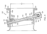
- FIG. 4 is a cross-sectional view taken along line 4-4 of FIG. 1 showing the outflow valve in a closed position
- FIG. 5 is a cross-sectional view taken along line 5-5 of FIG. 2 showing the outflow valve in an open position
- FIG. 6 is a cross-sectional view taken along line 6-6 of FIG. 2 showing a valve end-of-travel stop.
- the outflow valve 100 includes a dual wall valve housing 102.
- the outflow valve 100 also includes first and second drive shaft reinforcing sleeves 118, 120, a butterfly plate assembly 104 with a reinforcing ring 128, multiple fasteners 130 to fasten the reinforcing ring 128 to the plate assembly 104, multiple fasteners 136 to fasten the butterfly plate assembly 104 to a drive shaft 132, a valve end-of-travel stop 122, and a valve closing spring 144.
- the valve housing 102 includes a central bore with a dual wall formed of an inner sleeve 106 and an outer housing 108.
- the inner sleeve 106 may be made of any number of materials, but is preferably made of a high strength material, and preferably designed to handle the normal pressure load and valve mounting loads.
- the inner sleeve 106 may be made of a metal (e.g., aluminum) or a composite material (e.g., fiber reinforced PolyEtherImide (PEI), fiber reinforced Polyetheretherketon (PEEK)).
- PEI PolyEtherImide
- PEEK fiber reinforced Polyetheretherketon
- the inner diameter 110 of the inner sleeve 106 is a machined surface with tolerances and finishes to aid in valve wiper sealing (discussed further below).
- the length of the inner sleeve 106 may be limited to a length that supports the outer housing 108 around the drive shaft 132 and pressure vessel or the length of the inner sleeve 106 may be different on each side due to the angle of the drive shaft 132. As shown in FIG. 4, inner sleeve 106 is longer at the top portion than the bottom portion. However, the inner sleeve 106 may be of a substantially constant length.
- the outer housing 108 may be a molded plastic/composite material that is a high-strength material suitable for the environment of the valve (e.g., chemical, temperature, strength, durability, etc.).
- the outer housing 108 may be formed from a composite material, such as a fiber reinforced PolyEtherImide (PEI), fiber reinforced Polyetheretherketon (PEEK), or any other suitable composite material.
- PEI PolyEtherImide
- PEEK fiber reinforced Polyetheretherketon
- the outer housing 108 is preferably a molded part with geometric features that provide a bell-shaped inlet 111 that is configured to increase air speed and reduce the total pressure drop.
- the geometric features of the outer housing 108 have enveloping dimensions for reinforcing the inner sleeve 106 and that provide an actuator mounting interface 112, upper and lower housing bosses 114, 116 that support the upper/lower drive shaft reinforcing sleeves 118, 120, a valve rotational stop 122 (see FIG. 6), and a lower shaft spring cover 124.
- the outer housing 108 can be either molded over the inner sleeve 106, such as during an injection molding process, or it can be bonded to the inner sleeve 106 using a suitable adhesive. It should be understood that if the two are bonded, the bonding preferably does not fuse the inner sleeve 106 and outer housing 108 or form a single walled element. Rather, the bonding maintains the dual wall formed of the outer housing 108 and the inner sleeve 106, and this dual wall provides numerous advantages and improvements such as redundancy.
- the butterfly plate assembly 104 includes a wiper seal 125, a molded butterfly plate 126, and the previously mentioned reinforcing ring 128 that, as was also previously mentioned, are held together with multiple fasteners 130.
- the reinforcing ring 128 may be formed from steel, aluminum or other material or composite.
- the butterfly plate assembly 104 is fixed to an angled drive shaft 132 within the valve housing 102.
- the butterfly plate 126 may be manufactured out of a suitable plastic/composite material or metal that is molded to the geometry of the outer housing 108.
- the butterfly plate 126 may be manufactured out of fiber reinforced PolyEtherlmide (PEI), fiber reinforced Polyetheretherketon (PEEK), or aluminum.
- Preferable geometric interface features of the butterfly plate 126 are: aerodynamic shape, a mounting interface for the plate reinforcing ring/seal retaining ring 128, drive shaft mounting and fixing hardware, and reinforcement angled drive shaft sleeve 134 for the drive shaft 132.
- the reinforcing ring 128 may be manufactured from steel or other suitable material and is affixed to the butterfly plate 126 with multiple fasteners 130.
- the wiper seal 125 is a flat annular ring made of, for example, dacron reinforced silicon material.
- the wiper seal 125 can be made of any other suitable material or have any other suitable shape.
- the drive shaft 132 extends through the butterfly plate 126 and is mounted thereto using at least two fasteners 136.
- the butterfly plate 126 could also employ an internal serration, or other means, to mate with the drive shaft 132 and prevent non-driven butterfly plate rotation.
- the drive shaft 132 is shown as a single shaft. It will be appreciated, however, that the drive shaft 132 may also be made of two shafts, an upper drive shaft and lower drive shaft. If the draft shaft 132 is made of an upper drive shaft and a lower drive shaft, then the upper shaft is preferably fixed by at least two fasteners or a spline.
- the drive shaft 132 preferably mates with an actuator (not shown) on a first end 138 (e.g., upper end) and performs valve stop and closing torque functions on a second end 140 (e.g., lower end).
- a first end 138 e.g., upper end
- a second end 140 e.g., lower end
- the upper and lower end designations have no purpose except for ease of description and the upper and lower designations could be swapped with no adverse affect on the assembly and functionality.
- two drive shafts could be employed with slightly different installation design, but similar functions as the single shaft.
- the drive shaft 132 has an interface 142, such as a slot, on the first end 138 that can be driven by a pneumatic, electro-mechanical, or other type of actuator (not shown).
- the drive shaft 132 is installed into the butterfly plate 126 and is supported by drive shaft reinforcing sleeves 118, 120 at both the upper and lower housing bosses 114, 116.
- the drive shaft reinforcing sleeves 118, 120 may act both as a bearing and a reinforcing section for the drive shaft 132.
- the drive shaft reinforcing sleeve 118 extends through the shaft boss 114 of the valve housing 102 into the butterfly plate 126.
- the lower sleeve 120 extends from the valve housing 102 in order to provide a protrusion that inhibits a fully open butterfly plate 126.
- the drive shaft reinforcing sleeve 118, 120 preferably has the appropriate friction and wear properties. If the reinforcing sleeve 118, 120 is not used as a bearing, then it can be press fit onto the shaft 132 in any number of configurations. Alternatively, the reinforcing sleeve 118, 120 can be tolerance fit over the shaft (i.e., fixed into the valve housing) and a suitable ball bearing may be used in the upper and lower valve shaft bosses 114, 116.
- the lower valve shaft boss 116 employs a valve end-of-travel stop 122 that interacts with the shaft stop 146 as shown in FIG. 6.
- the end-of-travel stop 122 is employed on the lower shaft end 140 opposite the actuated upper shaft end 138 to prevent full rotation of the shaft 132.
- the end-of-travel stop 122 contacts the shaft stop 146 and limits the valve stroke to approximately the full-closed position.
- a valve closing torsion spring 144 is mounted on the lower shaft 140 opposite the actuated upper shaft end 138.
- the spring 144 engages a shaft boss 146 relative to the valve spring cover 124 to close the valve 104.
- the valve closing spring 144 closes the valve assembly 102.
- the valve closing torsion spring 144 can be any number of springs such as a leaf spring, a lever spring, or a compression spring.
Landscapes
- Engineering & Computer Science (AREA)
- General Engineering & Computer Science (AREA)
- Mechanical Engineering (AREA)
- Lift Valve (AREA)
Abstract
Description
- The present invention relates generally to outflow valves, and more particularly to butterfly outflow valves.
- Generally, high altitude aircraft have a Cabin Pressure Control System (CPCS) to manage the pressure of the aircraft cabin, which is an enclosed space within the fuselage of the aircraft that may contain the crew, passengers, and/or cargo. The CPCS exhausts air from the aircraft cabin in a controlled manner and typically uses an outflow valve. One type of outflow valve that is used in a CPCS is a butterfly outflow valve.
- The butterfly outflow valve contains a butterfly plate or disk that rotates on a drive shaft in the bore of a valve housing. Numerous advancements and improvements have been made in butterfly outflow valves, including numerous advancements and improvements in the butterfly plate. However, additional advancements and improvements are continually sought.
- Accordingly, it is desirable to provide advancements and improvements in outflow valves. In addition, it is desirable to provide advancements and improvements in butterfly outflow valves. Furthermore, it is desirable to provide advancements and improvements in butterfly outflow valves used in a CPCS. Moreover, other desirable features and characteristics of the present invention will become apparent from the subsequent detailed description and the appended claims, taken in conjunction with the accompanying drawings and the foregoing technical field and background
- An outflow valve is provided in accordance with one exemplary embodiment of the present invention. The outflow valve comprises a dual wall valve housing having a central bore and a butterfly plate assembly configured to rotate within the central bore. The outflow valve further comprises an angled drive shaft fixedly coupled to the butterfly plate assembly with multiple fasteners. The angled drive shaft comprises first and second ends rotateably coupled to the dual wall valve housing. The angled drive shaft is configured to rotate the butterfly plate assembly between a closed position and an open position.
- An outflow valve is also provided in accordance with another exemplary embodiment of the present invention. The outflow valve comprises a cylindrical valve housing, which includes an inner sleeve and an outer housing, and an angled drive shaft having first and second ends rotateably coupled to the cylindrical valve housing. The outflow valve also comprises a butterfly plate dimensioned to fit within the cylindrical valve housing and the butterfly plate is fixedly coupled to the angled drive shaft and configured to rotate with the angled drive shaft between a closed position and an open position. The outflow valve further comprises a wiper seal mounted around a perimeter of the butterfly plate and configured to sealingly engage the inner sleeve in the closed position.
- The following drawings are illustrative of the particular embodiments of the invention and therefore do not limit its scope. They are presented to assist in providing a proper understanding of the invention. The drawings are not to scale and are intended for use in conjunction with the explanations in the following detailed descriptions. The present invention will hereinafter be described in conjunction with the appended drawings, wherein like reference numerals denote like elements, and;
- FIG. 1 is a perspective view showing one embodiment of an outflow valve.
- FIG. 2 is a side view of the outflow valve of FIG. 1
- FIG. 3 is an exploded perspective view of the outflow valve of FIG. 1.
- FIG. 4 is a cross-sectional view taken along line 4-4 of FIG. 1 showing the outflow valve in a closed position;
- FIG. 5 is a cross-sectional view taken along line 5-5 of FIG. 2 showing the outflow valve in an open position; and
- FIG. 6 is a cross-sectional view taken along line 6-6 of FIG. 2 showing a valve end-of-travel stop.
- The following detailed description of the invention is merely exemplary in nature and is not intended to limit the invention or the application and uses of the invention. Furthermore, there is no intention to be bound by any theory presented in the preceding background of the invention or the following detailed
- Referring to FIGs. 1-5, an
outflow valve 100 is illustrated in accordance with an exemplary embodiment of the present invention. Theoutflow valve 100 includes a dualwall valve housing 102. Theoutflow valve 100 also includes first and second driveshaft reinforcing sleeves butterfly plate assembly 104 with areinforcing ring 128,multiple fasteners 130 to fasten thereinforcing ring 128 to theplate assembly 104,multiple fasteners 136 to fasten thebutterfly plate assembly 104 to adrive shaft 132, a valve end-of-travel stop 122, and avalve closing spring 144. - The
valve housing 102 includes a central bore with a dual wall formed of aninner sleeve 106 and anouter housing 108. Theinner sleeve 106 may be made of any number of materials, but is preferably made of a high strength material, and preferably designed to handle the normal pressure load and valve mounting loads. For example, theinner sleeve 106 may be made of a metal (e.g., aluminum) or a composite material (e.g., fiber reinforced PolyEtherImide (PEI), fiber reinforced Polyetheretherketon (PEEK)). Theinner diameter 110 of theinner sleeve 106 is a machined surface with tolerances and finishes to aid in valve wiper sealing (discussed further below). The length of theinner sleeve 106 may be limited to a length that supports theouter housing 108 around thedrive shaft 132 and pressure vessel or the length of theinner sleeve 106 may be different on each side due to the angle of thedrive shaft 132. As shown in FIG. 4,inner sleeve 106 is longer at the top portion than the bottom portion. However, theinner sleeve 106 may be of a substantially constant length. - The
outer housing 108 may be a molded plastic/composite material that is a high-strength material suitable for the environment of the valve (e.g., chemical, temperature, strength, durability, etc.). In one exemplary embodiment, theouter housing 108 may be formed from a composite material, such as a fiber reinforced PolyEtherImide (PEI), fiber reinforced Polyetheretherketon (PEEK), or any other suitable composite material. Theouter housing 108 is preferably a molded part with geometric features that provide a bell-shaped inlet 111 that is configured to increase air speed and reduce the total pressure drop. The geometric features of theouter housing 108 have enveloping dimensions for reinforcing theinner sleeve 106 and that provide anactuator mounting interface 112, upper andlower housing bosses shaft reinforcing sleeves shaft spring cover 124. - The
outer housing 108 can be either molded over theinner sleeve 106, such as during an injection molding process, or it can be bonded to theinner sleeve 106 using a suitable adhesive. It should be understood that if the two are bonded, the bonding preferably does not fuse theinner sleeve 106 andouter housing 108 or form a single walled element. Rather, the bonding maintains the dual wall formed of theouter housing 108 and theinner sleeve 106, and this dual wall provides numerous advantages and improvements such as redundancy. - The
butterfly plate assembly 104 includes awiper seal 125, a moldedbutterfly plate 126, and the previously mentionedreinforcing ring 128 that, as was also previously mentioned, are held together withmultiple fasteners 130. The reinforcingring 128 may be formed from steel, aluminum or other material or composite. Thebutterfly plate assembly 104 is fixed to anangled drive shaft 132 within thevalve housing 102. Thebutterfly plate 126 may be manufactured out of a suitable plastic/composite material or metal that is molded to the geometry of theouter housing 108. For example, thebutterfly plate 126 may be manufactured out of fiber reinforced PolyEtherlmide (PEI), fiber reinforced Polyetheretherketon (PEEK), or aluminum. Preferable geometric interface features of thebutterfly plate 126 are: aerodynamic shape, a mounting interface for the plate reinforcing ring/seal retaining ring 128, drive shaft mounting and fixing hardware, and reinforcement angleddrive shaft sleeve 134 for thedrive shaft 132. - The reinforcing
ring 128 may be manufactured from steel or other suitable material and is affixed to thebutterfly plate 126 withmultiple fasteners 130. In this exemplary embodiment, thewiper seal 125 is a flat annular ring made of, for example, dacron reinforced silicon material. However, thewiper seal 125 can be made of any other suitable material or have any other suitable shape. - The
drive shaft 132 extends through thebutterfly plate 126 and is mounted thereto using at least twofasteners 136. Thebutterfly plate 126 could also employ an internal serration, or other means, to mate with thedrive shaft 132 and prevent non-driven butterfly plate rotation. In the depicted embodiment, thedrive shaft 132 is shown as a single shaft. It will be appreciated, however, that thedrive shaft 132 may also be made of two shafts, an upper drive shaft and lower drive shaft. If thedraft shaft 132 is made of an upper drive shaft and a lower drive shaft, then the upper shaft is preferably fixed by at least two fasteners or a spline. In either case, thedrive shaft 132 preferably mates with an actuator (not shown) on a first end 138 (e.g., upper end) and performs valve stop and closing torque functions on a second end 140 (e.g., lower end). The upper and lower end designations have no purpose except for ease of description and the upper and lower designations could be swapped with no adverse affect on the assembly and functionality. Further, two drive shafts could be employed with slightly different installation design, but similar functions as the single shaft. - The
drive shaft 132 has aninterface 142, such as a slot, on thefirst end 138 that can be driven by a pneumatic, electro-mechanical, or other type of actuator (not shown). Thedrive shaft 132 is installed into thebutterfly plate 126 and is supported by driveshaft reinforcing sleeves lower housing bosses shaft reinforcing sleeves drive shaft 132. The driveshaft reinforcing sleeve 118 extends through theshaft boss 114 of thevalve housing 102 into thebutterfly plate 126. Thelower sleeve 120 extends from thevalve housing 102 in order to provide a protrusion that inhibits a fullyopen butterfly plate 126. - If the drive
shaft reinforcing sleeve shaft reinforcing sleeve sleeve shaft 132 in any number of configurations. Alternatively, the reinforcingsleeve valve shaft bosses - The lower
valve shaft boss 116 employs a valve end-of-travel stop 122 that interacts with the shaft stop 146 as shown in FIG. 6. The end-of-travel stop 122 is employed on thelower shaft end 140 opposite the actuatedupper shaft end 138 to prevent full rotation of theshaft 132. The end-of-travel stop 122 contacts theshaft stop 146 and limits the valve stroke to approximately the full-closed position. - A valve closing
torsion spring 144 is mounted on thelower shaft 140 opposite the actuatedupper shaft end 138. Thespring 144 engages ashaft boss 146 relative to thevalve spring cover 124 to close thevalve 104. In the event that there is a separation of thevalve butterfly plate 126 or driveshaft 132 from the rotary actuator, thevalve closing spring 144 closes thevalve assembly 102. The valveclosing torsion spring 144 can be any number of springs such as a leaf spring, a lever spring, or a compression spring. - While the invention has been described with reference to a preferred embodiment, it will be understood by those skilled in the art that various changes may be made and equivalents may be substituted for elements thereof without departing from the scope of the invention. In addition, many modifications may be made to adapt to a particular situation or material to the teachings of the invention without departing from the essential scope thereof. Therefore, it is intended that the invention not be limited to the particular embodiment disclosed as the best mode contemplated for carrying out this invention, but that the invention will include all embodiments falling within the scope of the appended claims.
Claims (10)
- An outflow valve (100), the outflow valve (100) comprising:a dual wall valve housing (102) having a central bore;a butterfly plate assembly (104) rotationally disposed within the central bore; andan angled drive shaft (132) coupled to the butterfly plate assembly (104) with a plurality of fasteners (136), the angled drive shaft (132) comprising first and second ends (138, 140) rotationally coupled to the dual wall valve housing (102) and configured to rotate the butterfly plate assembly (104) between a closed position and an open position.
- The outflow valve (100) of claim 1, further comprising:first and second drive shaft reinforcing sleeves (118, 120) coupled to the dual wall valve housing (102), wherein the first end (138) of the angled drive shaft (132) is rotateably coupled to the first drive shaft reinforcing sleeve (118) and the second end (140) of the angled drive shaft (132) is rotateably coupled to the second drive shaft reinforcing sleeve (120).
- The outflow valve (100) of claim 2, further comprising a closing spring (144) coupled to the second end (140) of the drive shaft (132) and configured to urge the butterfly plate assembly (104) toward the closed position.
- The outflow valve (100) of claim 1, the butterfly plate assembly (104) comprising:a butterfly plate (126);a wiper seal (125) mounted around a perimeter of the butterfly plate (126); anda butterfly plate reinforcing ring (128) coupled to the wiper seal (125) and butterfly plate (126) with a second plurality of fasteners (136).
- The outflow valve (100) of claim 1, wherein the dual wall valve housing (102) comprises an inner sleeve (106) and an outer housing (108).
- The outflow valve (100) of claim 7, wherein the inner sleeve (106) is at least partially formed from aluminum.
- The outflow valve (100) of claim 7, wherein the inner sleeve (106) is at least partially formed from fiber reinforced Polyetheretherketon (PEEK).
- The outflow valve (100) of claim 7, wherein the inner sleeve (106) is at least partially formed from fiber reinforced PolyEtherlmide (PEI).
- The outflow valve (100) of claim 7, wherein the outer housing (108) is at least partially formed from fiber reinforced PolyEtherlmide (PEI).
- The outflow valve (100) of claim 7, wherein the outer housing (108) is at least partially formed from fiber reinforced Polyetheretherketon (PEEK).
Applications Claiming Priority (1)
| Application Number | Priority Date | Filing Date | Title |
|---|---|---|---|
| US11/088,386 US7571742B2 (en) | 2005-03-23 | 2005-03-23 | Butterfly outflow valve |
Publications (2)
| Publication Number | Publication Date |
|---|---|
| EP1705409A1 true EP1705409A1 (en) | 2006-09-27 |
| EP1705409B1 EP1705409B1 (en) | 2009-04-15 |
Family
ID=36616938
Family Applications (1)
| Application Number | Title | Priority Date | Filing Date |
|---|---|---|---|
| EP20060251495 Expired - Lifetime EP1705409B1 (en) | 2005-03-23 | 2006-03-21 | Butterfly outflow valve |
Country Status (3)
| Country | Link |
|---|---|
| US (1) | US7571742B2 (en) |
| EP (1) | EP1705409B1 (en) |
| DE (1) | DE602006006241D1 (en) |
Cited By (7)
| Publication number | Priority date | Publication date | Assignee | Title |
|---|---|---|---|---|
| WO2008100342A3 (en) * | 2006-09-29 | 2008-10-30 | Sikorsky Aircraft Corp | Butterfly valves having sleeve inserts |
| US7571742B2 (en) | 2005-03-23 | 2009-08-11 | Honeywell International Inc. | Butterfly outflow valve |
| EP1975489A3 (en) * | 2007-03-28 | 2010-01-06 | Honeywell International Inc. | Design of a noise suppression wedge for a butterfly outflow valve |
| EP2306053A4 (en) * | 2008-06-27 | 2011-11-16 | Taiho Kogyo Co Ltd | FLOW CONTROL VALVE AND METHOD OF MANUFACTURING THE SAME |
| EP2191176B1 (en) * | 2007-08-21 | 2013-08-07 | Pentair Thermal Management Netherlands B.V. | Composite valve |
| WO2017062705A1 (en) * | 2015-10-07 | 2017-04-13 | Fisher Controls International Llc | Valve body insert apparatus and related methods |
| US10280845B2 (en) | 2014-12-19 | 2019-05-07 | Continental Automotive Gmbh | Valve device in a motor vehicle |
Families Citing this family (15)
| Publication number | Priority date | Publication date | Assignee | Title |
|---|---|---|---|---|
| US8371328B2 (en) * | 2007-11-27 | 2013-02-12 | GM Global Technology Operations LLC | Back pressure valve with inductively heated flap |
| US8056597B2 (en) * | 2008-04-10 | 2011-11-15 | Bps Engineering, Llc | Cam follower assembly for thin walled cylinder of scroll shaping drum used in tire construction |
| US20100108932A1 (en) * | 2008-10-31 | 2010-05-06 | Bauer Robert R | Bearing assembly and a method for controlling fluid flow within a conduit |
| US8632381B2 (en) * | 2010-01-04 | 2014-01-21 | Honeywell International Inc. | Lightweight cabin pressure thrust recovery outflow valve |
| DE102010054882A1 (en) * | 2010-12-17 | 2012-06-21 | Continental Automotive Gmbh | Valve with a gas flow regulating flap |
| US8662474B2 (en) * | 2011-02-04 | 2014-03-04 | Honeywell International Inc. | Combination bearings having improved load capacities and lifespan and valve assemblies including the same |
| USD686297S1 (en) * | 2011-06-21 | 2013-07-16 | Metso Automation Usa Inc. | Valve position communications and control module |
| FR3000149B1 (en) | 2012-12-21 | 2015-01-16 | Skf Aerospace France | METHOD FOR MANUFACTURING A BALL BEARING, IN PARTICULAR FOR A BUTTERFLY VALVE IN AERONAUTICAL ENVIRONMENT |
| CN103334920B (en) * | 2013-07-12 | 2015-12-09 | 株洲南方阀门股份有限公司 | A kind of tilt-disc check valve |
| US10401045B2 (en) * | 2014-02-13 | 2019-09-03 | Air Distribution Technologies Ip, Llc | Zone balancing damper and method of operation |
| US10203703B2 (en) * | 2014-03-04 | 2019-02-12 | Mi Valve, Llc | Airflow balancing valve for HVAC systems |
| US9677672B2 (en) * | 2014-11-05 | 2017-06-13 | Bulk Tank, Inc. | Butterfly valve having integral gaskets for its inlet and outlet seats |
| EP3234421A1 (en) * | 2014-12-19 | 2017-10-25 | Continental Automotive GmbH | Valve device in a motor vehicle |
| JP2019085902A (en) * | 2017-11-02 | 2019-06-06 | 株式会社ニッキ | Electric air quantity adjustment device |
| US11994220B1 (en) * | 2022-11-10 | 2024-05-28 | Caterpillar Inc. | Wear surface sleeve press fit onto a shaft in a high temperature air valve application |
Citations (9)
| Publication number | Priority date | Publication date | Assignee | Title |
|---|---|---|---|---|
| GB732184A (en) * | 1953-05-20 | 1955-06-22 | Teddington Aircraft Controls L | Improvements in or relating to butterfly valves |
| GB781183A (en) * | 1954-07-20 | 1957-08-14 | Teddington Aircraft Controls L | Improvements in or relating to butterfly valves |
| GB909420A (en) * | 1958-02-05 | 1962-10-31 | Sir George Godfrey And Partner | Improvements in or relating to butterfly valves |
| US3260502A (en) * | 1958-04-14 | 1966-07-12 | Parker Hannifin Corp | Butterfly valve |
| US4899984A (en) * | 1987-10-02 | 1990-02-13 | Abg Semca | Obturator ring for butterfly valve |
| US5664760A (en) | 1995-04-06 | 1997-09-09 | United Technologies Corporation | Pressure regulation valve with integrated downstream pressure tap |
| EP1126145A2 (en) * | 2000-02-16 | 2001-08-22 | Denso Corporation | Manufacturing method for a throttle body of an internal combustion engine and a related throttle apparatus |
| EP1362692A1 (en) * | 2002-05-17 | 2003-11-19 | Magneti Marelli Powertrain Spa | Bilayered pipe with an inner wall of polymeric material having a HDT-A of at least 275 C |
| DE10359609A1 (en) * | 2003-12-18 | 2005-07-28 | Siemens Ag | Throttle connection fitting for use in air conduit, has throttle valve that runs diagonally and aligned symmetrically between bearings of valve shaft, where longitudinal axes of valve and seat are normal |
Family Cites Families (38)
| Publication number | Priority date | Publication date | Assignee | Title |
|---|---|---|---|---|
| US2882010A (en) * | 1953-01-19 | 1959-04-14 | Walworth Co | Flow control valve |
| US2846934A (en) | 1953-08-10 | 1958-08-12 | Garrett Corp | Cabin pressure outflow valve |
| US2815705A (en) | 1953-11-10 | 1957-12-10 | Garrett Corp | Butterfly type safety valve |
| US2830521A (en) | 1955-03-01 | 1958-04-15 | Garrett Corp | Cabin pressure outflow valve |
| US3080145A (en) * | 1957-10-24 | 1963-03-05 | David F Wiseman & Sons Ltd | Butterfly valves |
| US3282555A (en) * | 1958-12-01 | 1966-11-01 | Garrett Corp | Floating convolute seal for butterfly valves |
| US3344808A (en) | 1964-11-23 | 1967-10-03 | New York Air Brake Co | Combined butterfly and check valve |
| US3384340A (en) * | 1965-06-25 | 1968-05-21 | Pratt Co Henry | Butterfly valve for high vacuum service |
| US3749359A (en) * | 1971-03-24 | 1973-07-31 | Dresser Ind | Valve seat construction |
| US3727837A (en) | 1971-06-21 | 1973-04-17 | Garrett Corp | Temperature responsive valve mechanism |
| US3905577A (en) * | 1973-03-08 | 1975-09-16 | Anchor Darling Valve Co | Valve |
| US3915587A (en) | 1973-09-27 | 1975-10-28 | United Technologies Corp | Variable size bleed port for jet engines |
| US4290615A (en) * | 1979-12-14 | 1981-09-22 | International Telephone And Telegraph Corporation | Butterfly valve |
| US4301831A (en) | 1980-03-17 | 1981-11-24 | United Aircraft Products, Inc. | Pressure regulating valve with differential pressure response |
| US4327765A (en) * | 1980-08-15 | 1982-05-04 | Dover Corporation | Butterfly valve having leak detecting means |
| US4324383A (en) * | 1980-09-11 | 1982-04-13 | Allis-Chalmers Corporation | Seat centerline operated butterfly valve |
| US4632360A (en) | 1981-08-14 | 1986-12-30 | United Aircraft Products, Inc. | Butterfly type valve seal |
| US4469305A (en) | 1981-10-22 | 1984-09-04 | Baumann Hans D | Low torque butterfly valve disc |
| US4489917A (en) | 1983-02-10 | 1984-12-25 | Baumann Hans D | Low torque valve disc for lined butterfly valves |
| US4516597A (en) * | 1983-04-01 | 1985-05-14 | Asahi Yukizai Kogyo Co., Ltd. | Anticorrosive butterfly valve |
| US5067506A (en) | 1989-06-30 | 1991-11-26 | Allied-Signal Inc. | Flight craft with fluid systems which incorporate butterfly valves, and butterfly valve methods and apparatus |
| US5238220A (en) | 1990-08-02 | 1993-08-24 | The Boeing Company | Manually and electrically controlled butterfly valve |
| US5076308A (en) | 1990-11-19 | 1991-12-31 | Sundstrand Corporation | Indicator for measuring amount of valve opening |
| US5203539A (en) * | 1991-12-17 | 1993-04-20 | Stary Gary M | Pipeline valve apparatus |
| JP2546566Y2 (en) * | 1992-04-10 | 1997-09-03 | 麓技研株式会社 | Operating valve for oil drain |
| US5351708A (en) | 1993-12-13 | 1994-10-04 | Symetrics | Automatic fluid sealing mechanism for a conduit with a frangible connector |
| US5465756A (en) | 1994-12-21 | 1995-11-14 | Alliedsignal Inc. | Butterfly valve plate for a pneumatic surge valve |
| US5640942A (en) * | 1996-01-16 | 1997-06-24 | Ford Motor Company | Ultraviolet cured throttle bore pre-coating |
| US6142173A (en) * | 1996-07-30 | 2000-11-07 | Spears Manufacturing Company | High purity corrosion resistant butterfly valve |
| US6283677B1 (en) * | 1997-03-03 | 2001-09-04 | The United States Of America As Represented By The Secretary Of The Navy | Tailorable elastomeric composite pneumatic fender system for absorbing high energy impact |
| DE10044294A1 (en) * | 2000-09-07 | 2002-05-16 | Siemens Ag | throttle body |
| JP3893907B2 (en) * | 2001-06-14 | 2007-03-14 | 株式会社デンソー | Intake control device for internal combustion engine |
| DE10138931A1 (en) * | 2001-08-08 | 2003-03-06 | Bosch Gmbh Robert | Throttle device housing with flexible compensating elements for internal combustion engines |
| US20030047703A1 (en) | 2001-09-10 | 2003-03-13 | Mark Patterson | Throttle valve apparatus for controlling fluid flow |
| US6694746B2 (en) | 2002-02-06 | 2004-02-24 | Honeywell International, Inc. | Micro volume actuator for an air turbine starter |
| JP2004300944A (en) * | 2003-03-28 | 2004-10-28 | Denso Corp | Throttle device for internal combustion engine |
| JP4575049B2 (en) * | 2004-07-02 | 2010-11-04 | 三菱電機株式会社 | Engine intake air amount control device |
| US7571742B2 (en) | 2005-03-23 | 2009-08-11 | Honeywell International Inc. | Butterfly outflow valve |
-
2005
- 2005-03-23 US US11/088,386 patent/US7571742B2/en not_active Expired - Lifetime
-
2006
- 2006-03-21 DE DE200660006241 patent/DE602006006241D1/en not_active Expired - Lifetime
- 2006-03-21 EP EP20060251495 patent/EP1705409B1/en not_active Expired - Lifetime
Patent Citations (9)
| Publication number | Priority date | Publication date | Assignee | Title |
|---|---|---|---|---|
| GB732184A (en) * | 1953-05-20 | 1955-06-22 | Teddington Aircraft Controls L | Improvements in or relating to butterfly valves |
| GB781183A (en) * | 1954-07-20 | 1957-08-14 | Teddington Aircraft Controls L | Improvements in or relating to butterfly valves |
| GB909420A (en) * | 1958-02-05 | 1962-10-31 | Sir George Godfrey And Partner | Improvements in or relating to butterfly valves |
| US3260502A (en) * | 1958-04-14 | 1966-07-12 | Parker Hannifin Corp | Butterfly valve |
| US4899984A (en) * | 1987-10-02 | 1990-02-13 | Abg Semca | Obturator ring for butterfly valve |
| US5664760A (en) | 1995-04-06 | 1997-09-09 | United Technologies Corporation | Pressure regulation valve with integrated downstream pressure tap |
| EP1126145A2 (en) * | 2000-02-16 | 2001-08-22 | Denso Corporation | Manufacturing method for a throttle body of an internal combustion engine and a related throttle apparatus |
| EP1362692A1 (en) * | 2002-05-17 | 2003-11-19 | Magneti Marelli Powertrain Spa | Bilayered pipe with an inner wall of polymeric material having a HDT-A of at least 275 C |
| DE10359609A1 (en) * | 2003-12-18 | 2005-07-28 | Siemens Ag | Throttle connection fitting for use in air conduit, has throttle valve that runs diagonally and aligned symmetrically between bearings of valve shaft, where longitudinal axes of valve and seat are normal |
Cited By (11)
| Publication number | Priority date | Publication date | Assignee | Title |
|---|---|---|---|---|
| US7571742B2 (en) | 2005-03-23 | 2009-08-11 | Honeywell International Inc. | Butterfly outflow valve |
| WO2008100342A3 (en) * | 2006-09-29 | 2008-10-30 | Sikorsky Aircraft Corp | Butterfly valves having sleeve inserts |
| US8091862B2 (en) | 2006-09-29 | 2012-01-10 | Sikorsky Aircraft Corporation | Butterfly valves having sleeve inserts |
| EP1975489A3 (en) * | 2007-03-28 | 2010-01-06 | Honeywell International Inc. | Design of a noise suppression wedge for a butterfly outflow valve |
| US7815163B2 (en) | 2007-03-28 | 2010-10-19 | Honeywell International Inc. | Design of a noise suppression wedge for a butterfly outflow valve |
| EP2191176B1 (en) * | 2007-08-21 | 2013-08-07 | Pentair Thermal Management Netherlands B.V. | Composite valve |
| EP2306053A4 (en) * | 2008-06-27 | 2011-11-16 | Taiho Kogyo Co Ltd | FLOW CONTROL VALVE AND METHOD OF MANUFACTURING THE SAME |
| US8434506B2 (en) | 2008-06-27 | 2013-05-07 | Taiho Kogyo Co., Ltd. | Flow control valve and method for manufacturing the same |
| US10280845B2 (en) | 2014-12-19 | 2019-05-07 | Continental Automotive Gmbh | Valve device in a motor vehicle |
| WO2017062705A1 (en) * | 2015-10-07 | 2017-04-13 | Fisher Controls International Llc | Valve body insert apparatus and related methods |
| RU2728410C2 (en) * | 2015-10-07 | 2020-07-30 | Фишер Контролз Интернешнел Ллс | Valve body insert device and associated methods |
Also Published As
| Publication number | Publication date |
|---|---|
| US7571742B2 (en) | 2009-08-11 |
| EP1705409B1 (en) | 2009-04-15 |
| US20060214128A1 (en) | 2006-09-28 |
| DE602006006241D1 (en) | 2009-05-28 |
Similar Documents
| Publication | Publication Date | Title |
|---|---|---|
| EP1705409B1 (en) | Butterfly outflow valve | |
| US8181755B2 (en) | Dual spring rate damper | |
| US8360393B2 (en) | Valve actuator having spring return power | |
| US7325569B2 (en) | Butterfly valve with integral split flapper relief valve | |
| EP2665945B1 (en) | A temperature adaptive fluid damping system | |
| EP1832512A2 (en) | Compact, lightweight cabin pressure control system butterfly outflow valve with redundancy features | |
| US9481469B2 (en) | Valve for controlling the internal pressure in a cabin of an aircraft | |
| US6216737B1 (en) | Flanged three-way universal butterfly valve | |
| JPH09507560A (en) | Self-aligning piston | |
| US7334773B2 (en) | Outflow valve having a cable operated closure mechanism | |
| CN109154348A (en) | Vibration isolating suspension | |
| US20080000628A1 (en) | Single point direct actuation of two air devices | |
| CN107108016A (en) | Aircraft, control surface assembly and method of assembling an aircraft | |
| CN107165727B (en) | Drive system for exhaust flap valve | |
| WO2008054842A2 (en) | Strap actuated flapper valve | |
| US20080035872A1 (en) | Outflow valve | |
| EP2007623B1 (en) | Rotor apparatus and methods for vertical lift aircraft | |
| US12259031B2 (en) | Balanced harmonic drive with output shaft disconnect | |
| RU2158215C1 (en) | Hatch cover assembly unit of flying vehicle thermostating system | |
| EP3964737B1 (en) | Butterfly valve with vibration resistant mount | |
| EP3371049B1 (en) | Rotor blade snubber retainer for a rotary wing aircraft | |
| EP1958874A2 (en) | Lightweight composite material and metal thrust recovery flapper valve | |
| WO2016188969A1 (en) | Module for heating, ventilation and/or air conditioning of a passenger compartment of a motor vehicle | |
| EP4520659B1 (en) | No-back brake having a limited authority damper | |
| JPH0155708B2 (en) |
Legal Events
| Date | Code | Title | Description |
|---|---|---|---|
| PUAI | Public reference made under article 153(3) epc to a published international application that has entered the european phase |
Free format text: ORIGINAL CODE: 0009012 |
|
| AK | Designated contracting states |
Kind code of ref document: A1 Designated state(s): AT BE BG CH CY CZ DE DK EE ES FI FR GB GR HU IE IS IT LI LT LU LV MC NL PL PT RO SE SI SK TR |
|
| AX | Request for extension of the european patent |
Extension state: AL BA HR MK YU |
|
| 17P | Request for examination filed |
Effective date: 20070319 |
|
| 17Q | First examination report despatched |
Effective date: 20070504 |
|
| AKX | Designation fees paid |
Designated state(s): DE FR GB |
|
| GRAP | Despatch of communication of intention to grant a patent |
Free format text: ORIGINAL CODE: EPIDOSNIGR1 |
|
| GRAP | Despatch of communication of intention to grant a patent |
Free format text: ORIGINAL CODE: EPIDOSNIGR1 |
|
| GRAS | Grant fee paid |
Free format text: ORIGINAL CODE: EPIDOSNIGR3 |
|
| GRAA | (expected) grant |
Free format text: ORIGINAL CODE: 0009210 |
|
| AK | Designated contracting states |
Kind code of ref document: B1 Designated state(s): DE FR GB |
|
| REG | Reference to a national code |
Ref country code: GB Ref legal event code: FG4D |
|
| REF | Corresponds to: |
Ref document number: 602006006241 Country of ref document: DE Date of ref document: 20090528 Kind code of ref document: P |
|
| PLBE | No opposition filed within time limit |
Free format text: ORIGINAL CODE: 0009261 |
|
| STAA | Information on the status of an ep patent application or granted ep patent |
Free format text: STATUS: NO OPPOSITION FILED WITHIN TIME LIMIT |
|
| 26N | No opposition filed |
Effective date: 20100118 |
|
| PGFP | Annual fee paid to national office [announced via postgrant information from national office to epo] |
Ref country code: FR Payment date: 20100318 Year of fee payment: 5 |
|
| PGFP | Annual fee paid to national office [announced via postgrant information from national office to epo] |
Ref country code: GB Payment date: 20100208 Year of fee payment: 5 |
|
| PGFP | Annual fee paid to national office [announced via postgrant information from national office to epo] |
Ref country code: DE Payment date: 20100331 Year of fee payment: 5 |
|
| GBPC | Gb: european patent ceased through non-payment of renewal fee |
Effective date: 20110321 |
|
| REG | Reference to a national code |
Ref country code: FR Ref legal event code: ST Effective date: 20111130 |
|
| PG25 | Lapsed in a contracting state [announced via postgrant information from national office to epo] |
Ref country code: FR Free format text: LAPSE BECAUSE OF NON-PAYMENT OF DUE FEES Effective date: 20110331 Ref country code: DE Free format text: LAPSE BECAUSE OF NON-PAYMENT OF DUE FEES Effective date: 20111001 |
|
| REG | Reference to a national code |
Ref country code: DE Ref legal event code: R119 Ref document number: 602006006241 Country of ref document: DE Effective date: 20111001 |
|
| PG25 | Lapsed in a contracting state [announced via postgrant information from national office to epo] |
Ref country code: GB Free format text: LAPSE BECAUSE OF NON-PAYMENT OF DUE FEES Effective date: 20110321 |
|
| P01 | Opt-out of the competence of the unified patent court (upc) registered |
Effective date: 20230525 |