EP1705379A1 - Screw compressor - Google Patents
Screw compressor Download PDFInfo
- Publication number
- EP1705379A1 EP1705379A1 EP03780975A EP03780975A EP1705379A1 EP 1705379 A1 EP1705379 A1 EP 1705379A1 EP 03780975 A EP03780975 A EP 03780975A EP 03780975 A EP03780975 A EP 03780975A EP 1705379 A1 EP1705379 A1 EP 1705379A1
- Authority
- EP
- European Patent Office
- Prior art keywords
- screw
- oil
- casing body
- compressor
- rotor
- Prior art date
- Legal status (The legal status is an assumption and is not a legal conclusion. Google has not performed a legal analysis and makes no representation as to the accuracy of the status listed.)
- Granted
Links
Images


Classifications
-
- F—MECHANICAL ENGINEERING; LIGHTING; HEATING; WEAPONS; BLASTING
- F04—POSITIVE - DISPLACEMENT MACHINES FOR LIQUIDS; PUMPS FOR LIQUIDS OR ELASTIC FLUIDS
- F04C—ROTARY-PISTON, OR OSCILLATING-PISTON, POSITIVE-DISPLACEMENT MACHINES FOR LIQUIDS; ROTARY-PISTON, OR OSCILLATING-PISTON, POSITIVE-DISPLACEMENT PUMPS
- F04C29/00—Component parts, details or accessories of pumps or pumping installations, not provided for in groups F04C18/00 - F04C28/00
- F04C29/02—Lubrication; Lubricant separation
- F04C29/028—Means for improving or restricting lubricant flow
-
- F—MECHANICAL ENGINEERING; LIGHTING; HEATING; WEAPONS; BLASTING
- F04—POSITIVE - DISPLACEMENT MACHINES FOR LIQUIDS; PUMPS FOR LIQUIDS OR ELASTIC FLUIDS
- F04C—ROTARY-PISTON, OR OSCILLATING-PISTON, POSITIVE-DISPLACEMENT MACHINES FOR LIQUIDS; ROTARY-PISTON, OR OSCILLATING-PISTON, POSITIVE-DISPLACEMENT PUMPS
- F04C18/00—Rotary-piston pumps specially adapted for elastic fluids
- F04C18/08—Rotary-piston pumps specially adapted for elastic fluids of intermeshing-engagement type, i.e. with engagement of co-operating members similar to that of toothed gearing
- F04C18/12—Rotary-piston pumps specially adapted for elastic fluids of intermeshing-engagement type, i.e. with engagement of co-operating members similar to that of toothed gearing of other than internal-axis type
- F04C18/14—Rotary-piston pumps specially adapted for elastic fluids of intermeshing-engagement type, i.e. with engagement of co-operating members similar to that of toothed gearing of other than internal-axis type with toothed rotary pistons
- F04C18/16—Rotary-piston pumps specially adapted for elastic fluids of intermeshing-engagement type, i.e. with engagement of co-operating members similar to that of toothed gearing of other than internal-axis type with toothed rotary pistons with helical teeth, e.g. chevron-shaped, screw type
-
- F—MECHANICAL ENGINEERING; LIGHTING; HEATING; WEAPONS; BLASTING
- F04—POSITIVE - DISPLACEMENT MACHINES FOR LIQUIDS; PUMPS FOR LIQUIDS OR ELASTIC FLUIDS
- F04C—ROTARY-PISTON, OR OSCILLATING-PISTON, POSITIVE-DISPLACEMENT MACHINES FOR LIQUIDS; ROTARY-PISTON, OR OSCILLATING-PISTON, POSITIVE-DISPLACEMENT PUMPS
- F04C29/00—Component parts, details or accessories of pumps or pumping installations, not provided for in groups F04C18/00 - F04C28/00
- F04C29/0007—Injection of a fluid in the working chamber for sealing, cooling and lubricating
-
- F—MECHANICAL ENGINEERING; LIGHTING; HEATING; WEAPONS; BLASTING
- F04—POSITIVE - DISPLACEMENT MACHINES FOR LIQUIDS; PUMPS FOR LIQUIDS OR ELASTIC FLUIDS
- F04C—ROTARY-PISTON, OR OSCILLATING-PISTON, POSITIVE-DISPLACEMENT MACHINES FOR LIQUIDS; ROTARY-PISTON, OR OSCILLATING-PISTON, POSITIVE-DISPLACEMENT PUMPS
- F04C29/00—Component parts, details or accessories of pumps or pumping installations, not provided for in groups F04C18/00 - F04C28/00
- F04C29/04—Heating; Cooling; Heat insulation
- F04C29/045—Heating; Cooling; Heat insulation of the electric motor in hermetic pumps
-
- F—MECHANICAL ENGINEERING; LIGHTING; HEATING; WEAPONS; BLASTING
- F04—POSITIVE - DISPLACEMENT MACHINES FOR LIQUIDS; PUMPS FOR LIQUIDS OR ELASTIC FLUIDS
- F04C—ROTARY-PISTON, OR OSCILLATING-PISTON, POSITIVE-DISPLACEMENT MACHINES FOR LIQUIDS; ROTARY-PISTON, OR OSCILLATING-PISTON, POSITIVE-DISPLACEMENT PUMPS
- F04C2270/00—Control; Monitoring or safety arrangements
- F04C2270/17—Tolerance; Play; Gap
-
- F—MECHANICAL ENGINEERING; LIGHTING; HEATING; WEAPONS; BLASTING
- F04—POSITIVE - DISPLACEMENT MACHINES FOR LIQUIDS; PUMPS FOR LIQUIDS OR ELASTIC FLUIDS
- F04C—ROTARY-PISTON, OR OSCILLATING-PISTON, POSITIVE-DISPLACEMENT MACHINES FOR LIQUIDS; ROTARY-PISTON, OR OSCILLATING-PISTON, POSITIVE-DISPLACEMENT PUMPS
- F04C28/00—Control of, monitoring of, or safety arrangements for, pumps or pumping installations specially adapted for elastic fluids
- F04C28/06—Control of, monitoring of, or safety arrangements for, pumps or pumping installations specially adapted for elastic fluids specially adapted for stopping, starting, idling or no-load operation
-
- F—MECHANICAL ENGINEERING; LIGHTING; HEATING; WEAPONS; BLASTING
- F04—POSITIVE - DISPLACEMENT MACHINES FOR LIQUIDS; PUMPS FOR LIQUIDS OR ELASTIC FLUIDS
- F04C—ROTARY-PISTON, OR OSCILLATING-PISTON, POSITIVE-DISPLACEMENT MACHINES FOR LIQUIDS; ROTARY-PISTON, OR OSCILLATING-PISTON, POSITIVE-DISPLACEMENT PUMPS
- F04C28/00—Control of, monitoring of, or safety arrangements for, pumps or pumping installations specially adapted for elastic fluids
- F04C28/28—Safety arrangements; Monitoring
-
- F—MECHANICAL ENGINEERING; LIGHTING; HEATING; WEAPONS; BLASTING
- F05—INDEXING SCHEMES RELATING TO ENGINES OR PUMPS IN VARIOUS SUBCLASSES OF CLASSES F01-F04
- F05C—INDEXING SCHEME RELATING TO MATERIALS, MATERIAL PROPERTIES OR MATERIAL CHARACTERISTICS FOR MACHINES, ENGINES OR PUMPS OTHER THAN NON-POSITIVE-DISPLACEMENT MACHINES OR ENGINES
- F05C2251/00—Material properties
- F05C2251/04—Thermal properties
- F05C2251/048—Heat transfer
Definitions
- the present invention relates to a screw compressor for compressing refrigerant gas.
- the invention relates to a screw compressor in which the oil to be introduced into the compression chamber and bearings to seal gaps in the compression chamber and lubricate the bearings is cooled to achieve high adiabatic efficiency and high volumetric efficiency.
- the present invention also relates to a screw compressor in which the difference in thermal expansion between the screw rotor and the screw bore portion of the casing body due to their temperature difference is reduced to prevent contact between the screw rotor and the screw bore portion due to a reduction in the gap between them.
- the present invention also relates to a screw compressor which prevents liquid compression by causing the liquid refrigerant to exchange heat when it flows into the compressor, thereby achieving increased resistance to returned liquid refrigerant.
- Conventional screw compressors have been configured such that the oil for sealing gaps in the compression chamber and lubricating the bearings is introduced from the high pressure side into the compression chamber and the bearings at nearly the discharge gas temperature. Since a conventional screw compressor has a configuration in which the oil for sealing gaps in the compression chamber and lubricating the bearings is introduced from the high pressure side into the compression chamber and the bearings at nearly the discharge gas temperature, the temperature of the compression chamber becomes higher than necessary, which increases the discharge gas temperature and hence the oil temperature, falling into a vicious circle. If liquid refrigerant is injected into the compressor to prevent this, the adiabatic efficiency and volumetric efficiency of the compressor decreases.
- Some conventional screw compressors use the discharge gas to heat the screw bore portion of the casing to reduce the difference in thermal expansion between the screw rotor and the screw bore portion of the casing.
- Japanese Laid-Open Patent Publication No. 6-42474 discloses a screw compressor in which the discharge gas path is extended close to the edge of the screw rotor in the axial direction on the suction side. This structure can prevent the temperature of the low pressure chamber from greatly affecting the inner cylinder of the casing which covers the outer circumferential surface of the screw rotor, thereby preventing seizure between the screw rotor and the inner cylinder of the casing while maintaining high performance without increasing the seal gap between the screw rotor and the inner cylinder.
- the present invention has been devised to solve the above problems. It is, therefore, an object of the present invention to provide a screw compressor in which the oil to be introduced into the compression chamber and bearings to seal gaps in the compression chamber and lubricate the bearings is cooled to achieve high adiabatic efficiency and high volumetric efficiency.
- Another object of the present invention is to provide a screw compressor in which the difference in thermal expansion between the screw rotor and the screw bore portion of the casing body due to their temperature difference is reduced to prevent contact between the screw rotor and the screw bore portion due to a reduction in the gap between them.
- Still another object of the present invention is to provide a screw compressor which prevents liquid compression by causing the liquid refrigerant to exchange heat when it flows into the compressor, thereby achieving increased resistance to returned liquid refrigerant.
- Yet another object of the present invention is to provide a screw compressor in which dew is prevented from being formed on the power terminal portion of the motor disposed in the casing body.
- an oil path is provided in the casing body such that the oil for sealing gaps in the compression chamber and lubricating the bearings is circulated to the vicinity of the low pressure side.
- the above oil path is provided in the screw bore outer circumferential portion of the casing body.
- a heat sink is provided to increase the heat transfer area for exchanging heat with refrigerant gas or liquid refrigerant passed through the motor chamber.
- Fig. 1 is a cross-sectional view of a screw compressor according to a first embodiment of the present invention.
- a motor 2 is fixed to the inside walls of a cylindrical casing body 1 constituting the body of the screw compressor.
- the motor 2 includes: a stator 3 fixed to the inside walls of the casing body 1; and a rotor 4 disposed inside the stator 3.
- a screw rotor 5 is also disposed within the casing body 1.
- the screw rotor 5 and the motor rotor 4 are attached to a screw shaft 6 such that their axes are aligned.
- the screw rotor 5 has a plurality of spiral compression grooves formed therein and is connected through the screw shaft 6 to the motor 2, which rotates the screw rotor 5.
- a motor cover 7 and an oil separator 8 are each fixed to a respective end of the casing body 1.
- the oil to be introduced into a compression chamber 9 to seal the gap between the inner circumferential surface of the casing body 1 and the outer circumferential surface of the screw rotor 5 in the compression chamber 9 is circulated to the vicinity of the low pressure side such as a low pressure chamber 10 of the compressor. More specifically, within the casing body 1, an oil path 11 is formed in a screw bore outer circumferential portion 1b of a screw casing portion 1a (inside of which the screw rotor 5 is disposed) such that the oil path 11 extends from the compression chamber 9 to the low pressure chamber 10 of the compressor.
- the oil to be introduced into the compression chamber 9 is cooled by the cool refrigerant near the low pressure side, making it possible to remove the heat of compression when the cooled oil is put into the compression chamber 9.
- This arrangement also prevents the reduction in the adiabatic and volumetric efficiency due to the liquid refrigerant injected to remove the heat of compression.
- the reduction in the temperature of the oil increases the viscosity of the oil and hence improves gap sealing performance, allowing the screw compressor to have high efficiency.
- the oil path 11 for circulating the oil to the vicinity of the low pressure side is formed in the screw bore outer circumferential portion 1b of the screw casing portion 1a, the oil of nearly the discharge gas temperature warms the screw bore outer circumferential portion 1b until it reaches the vicinity of the low pressure side (i.e., the low temperature portion) of the screw casing portion 1a. This improves the thermal response of the screw casing portion 1a with respect to the discharge gas temperature, making it possible to reduce the difference in thermal expansion between the screw rotor 5 and the screw casing portion 1a.
- the oil path 11 is formed in the screw bore outer circumferential portion 1b of the screw casing portion 1a so as to warm the screw casing portion 1a by the oil, as described above, a sufficient amount of oil is supplied even when the pressure differential is large and hence the discharge gas rate is reduced, meaning that the effect of warming the screw casing portion 1a is not reduced. Therefore, it is possible to reduce the difference in thermal expansion between the screw rotor 5 and the screw casing portion 1a, allowing the screw compressor to have high reliability.
- the oil circulation path 11 may be formed to have the following configuration.
- the oil path 11 runs from the oil separator 8 through the screw bore outer circumferential portion 1b of the screw casing portion 1a to warm the screw bore portion 4b with the oil. Then, the path goes to the low pressure side (the low pressure chamber 10 of the compressor, the motor chamber, etc.) to cool the oil, which is then put into the compression chamber 9.
- the low pressure side the low pressure chamber 10 of the compressor, the motor chamber, etc.
- Fig. 2 is a cross-sectional view of a screw compressor according to a second embodiment of the present invention.
- an external oil path 11a protruding externally of the casing body 1 is added to the oil path 11.
- a solenoid valve 12 is attached to this external oil path 11a so as to control the oil flow, allowing or not allowing the oil to pass.
- the solenoid valve 12 may be closed to stop the oil flow in order to prevent an increase in the gap between the screw rotor 5 and the screw bore portion of the screw casing portion 1a.
- the oil may be allowed to flow through the oil path 11 only when the gap between the screw rotor 5 and the screw bore portion of the screw casing portion 1a is reduced due to the expansion of the screw rotor 5 caused by increased discharge gas temperature, etc.
- it is possible to ensure the reliability of the screw compressor while preventing the reduction in the volumetric efficiency due to an increase in the gap in normal operation.
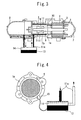
- Fig. 3 is a cross-sectional view of a screw compressor according to a third embodiment of the present invention.
- the oil trapped in the oil separator 8 is drawn into the oil path 11.
- the third embodiment is configured such that an oil temperature control device 13 is provided on the inlet side of the oil path 11 and the oil is introduced to the oil path 11 through the oil temperature control device 13.
- Fig. 3 shows an example in which the oil temperature control device 13 is provided in an oil tank 14 outside the compressor, it may be installed in the oil trapping portion (that is, the lower portion) of the oil separator 8 within the compressor.
- the oil temperature may be adjusted in the oil temperature control device 13 so as to heat the screw casing portion 1a and thereby expand the screw bore portion when the compression ratio or the discharge gas temperature is high, which makes it possible to minimize the difference in thermal expansion between the screw casing portion 1a and the screw rotor 5 and prevent their contact.
- the above oil temperature control may be performed so as to cool the oil, which then may be put into the compression chamber 9.
- Such an arrangement allows prevention of seizure, etc. due to the expansion of the screw rotor 5, achieving high reliability.
- the increase in the oil viscosity results in an increase in the sealing performance, allowing the screw compressor to have high efficiency.
- the above oil temperature control device 13 may be divided into two portions each disposed on a respective side of the screw bore outer circumferential portion 1b of the screw casing portion 1a.
- the oil may be set at a high temperature before it is passed through the screw bore outer circumferential portion 1b. Then, after the oil is passed through the screw bore outer circumferential portion 1b, it may be set at a low temperature. This allows effectively providing increased adiabatic efficiency and volumetric efficiency through cooling of the oil, as well as increased reliability through warming of the casing.
- the discharge gas temperature may be detected and the oil temperature may be controlled according to the temperature or the degree of superheat of the discharge gas. For example, when the discharge gas temperature is high (exceeding 100°C), the oil temperature may be increased to further expand the screw casing portion 1a and thereby prevent contact between the screw rotor 5 and the screw bore portion of the screw casing portion 1a.
- a noncontact/eddy current type gap detector 15, etc. may be attached to detect the gap between the screw casing portion 1a and the screw rotor 5, as shown in Fig. 4. Then, in the above oil temperature control, the oil temperature may be controlled while detecting the gap, allowing the gap between the screw rotor 5 and the screw casing portion 1a to be minimized. This allows the screw compressor to achieve reduced internal leak, as well as high performance and high reliability.
- the oil path 11 is formed in the screw bore outer circumferential portion 1b, as described above.
- the third embodiment is configured such that the temperature of the circulating oil is controlled, also as described above.
- the oil path 11 may be divided into upper and lower paths.
- the above lower path of the oil path 11 may be set to have a larger heat transfer area than the upper path, or the oil supplied to the lower path may be set at a higher temperature than the oil supplied to the upper path, or oil may be supplied to only the lower path, in order to warm the lower portion of the compressor.
- Such arrangements reduce the temperature difference between the upper and lower portions of the compressor, allowing the compressor to have resistance to returned liquid refrigerant and high reliability.
- the oil flow rate may be increased accordingly.
- appropriately controlling the oil flow rate enhances the resistance to returned liquid refrigerant.
- Fig. 5 is a cross-sectional view of a screw compressor according to a fourth embodiment of the present invention.
- the oil path 11 is formed so as to circulate the high temperature oil to the vicinity of the low pressure side, as described above.
- the fourth embodiment is configured such that part or all of the oil path, denoted by 11b, is extended so as to circulate the oil close to the power terminal portion 16 and the terminal block 17 of the motor 2 disposed in the casing body 1 of the compressor.
- dew may be formed on the terminal block 17 and the power terminal portion 16, depending on the ambient temperature and humidity conditions, which might lead to a short circuit in the power supply.
- circulating the oil close to the power terminal portion 16 and the terminal block 17 and thereby warming them prevents dew from being formed thereon, allowing the screw compressor to have enhanced reliability.
- Fig. 6 is a cross-sectional view of a screw compressor according to a fifth embodiment of the present invention.
- the oil path 11 is formed so as to circulate the oil to the vicinity of the low pressure side, as described above.
- the fifth embodiment is configured such that the oil path 11 is formed so as to circulate the oil to the vicinity of a boundary wall lc of the casing body 1 constituting the boundary between the motor chamber 2 and the compressor low-pressure chamber 10 on the low pressure side, as shown in Fig. 6, for example.
- a heat sink 18 may be attached to the boundary wall lc such that it sits on both the motor chamber 2 and the compressor low-pressure chamber 10 to increase the heat transfer area for cooling the oil circulated to the boundary wall 1c.
- the heat sink 18 which is attached to the boundary wall 1c of the casing body 1 such that it sits on both the motor chamber 2 and the compressor low-pressure chamber 10 may be provided with cooling fins to improve its heat exchange performance.
- the oil to be introduced into the compression chamber is circulated to the vicinity of the low pressure side and thereby cooled.
- the cooled oil is put into the compression chamber so as to be able to remove the heat of compression and thereby prevent the adiabatic efficiency and volumetric efficiency from being reduced.
- the reduction in the oil temperature increases the viscosity of the oil and hence enhances the oil gap sealing performance, allowing the screw compressor to have high efficiency.
- a heat sink is attached near the boundary position between the motor chamber and the compressor lower-pressure chamber on the low pressure side to increase the heat transfer area for cooling the oil.
Landscapes
- Engineering & Computer Science (AREA)
- Mechanical Engineering (AREA)
- General Engineering & Computer Science (AREA)
- Applications Or Details Of Rotary Compressors (AREA)
Abstract
Description
- The present invention relates to a screw compressor for compressing refrigerant gas. In particular, the invention relates to a screw compressor in which the oil to be introduced into the compression chamber and bearings to seal gaps in the compression chamber and lubricate the bearings is cooled to achieve high adiabatic efficiency and high volumetric efficiency. The present invention also relates to a screw compressor in which the difference in thermal expansion between the screw rotor and the screw bore portion of the casing body due to their temperature difference is reduced to prevent contact between the screw rotor and the screw bore portion due to a reduction in the gap between them. The present invention also relates to a screw compressor which prevents liquid compression by causing the liquid refrigerant to exchange heat when it flows into the compressor, thereby achieving increased resistance to returned liquid refrigerant.
- Conventional screw compressors have been configured such that the oil for sealing gaps in the compression chamber and lubricating the bearings is introduced from the high pressure side into the compression chamber and the bearings at nearly the discharge gas temperature. Since a conventional screw compressor has a configuration in which the oil for sealing gaps in the compression chamber and lubricating the bearings is introduced from the high pressure side into the compression chamber and the bearings at nearly the discharge gas temperature, the temperature of the compression chamber becomes higher than necessary, which increases the discharge gas temperature and hence the oil temperature, falling into a vicious circle. If liquid refrigerant is injected into the compressor to prevent this, the adiabatic efficiency and volumetric efficiency of the compressor decreases. The reduction in the viscosity of the oil at high temperatures also leads to a decrease in the adiabatic and volumetric efficiency. Furthermore, when the oil is introduced into the compression chamber at nearly the discharge gas temperature, the screw rotor thermally expands more quickly than the screw bore portion of the casing since the screw rotor has smaller heat capacity. Consequently, the gap between the screw rotor and the screw bore portion of the casing decreases, which might lead to contact between the screw rotor and the screw bore portion and hence an inability to operate the screw compressor properly if the initial gap is set too small.
- Some conventional screw compressors use the discharge gas to heat the screw bore portion of the casing to reduce the difference in thermal expansion between the screw rotor and the screw bore portion of the casing. For example,
Japanese Laid-Open Patent Publication No. 6-42474 - With this conventional screw compressor, however, the pressure differential may increase depending on the operating conditions, resulting in a reduced discharge gas rate. This reduces the effect of the above structure for improving the thermal response of the screw bore portion of the casing and thereby increases the difference in thermal expansion between the screw rotor and the screw bore portion of the casing, which might lead to their contact.
- The present invention has been devised to solve the above problems. It is, therefore, an object of the present invention to provide a screw compressor in which the oil to be introduced into the compression chamber and bearings to seal gaps in the compression chamber and lubricate the bearings is cooled to achieve high adiabatic efficiency and high volumetric efficiency.
- Another object of the present invention is to provide a screw compressor in which the difference in thermal expansion between the screw rotor and the screw bore portion of the casing body due to their temperature difference is reduced to prevent contact between the screw rotor and the screw bore portion due to a reduction in the gap between them.
- Still another object of the present invention is to provide a screw compressor which prevents liquid compression by causing the liquid refrigerant to exchange heat when it flows into the compressor, thereby achieving increased resistance to returned liquid refrigerant.
- Yet another object of the present invention is to provide a screw compressor in which dew is prevented from being formed on the power terminal portion of the motor disposed in the casing body.
- In a screw compressor of the present invention, an oil path is provided in the casing body such that the oil for sealing gaps in the compression chamber and lubricating the bearings is circulated to the vicinity of the low pressure side.
- In another screw compressor of the present invention, the above oil path is provided in the screw bore outer circumferential portion of the casing body.
- In still another screw compressor of the present invention, a heat sink is provided to increase the heat transfer area for exchanging heat with refrigerant gas or liquid refrigerant passed through the motor chamber.
-
- Fig. 1 is a cross-sectional view of a screw compressor according to a first embodiment of the present invention.
- Fig. 2 is a cross-sectional view of a screw compressor according to a second embodiment of the present invention.
- Fig. 3 is a cross-sectional view of a screw compressor according to a third embodiment of the present invention.
- Fig. 4 is a partial structural view of the screw compressor according to the third embodiment of the present invention.
- Fig. 5 is a cross-sectional view of a screw compressor according to a fourth embodiment of the present invention.
- Fig. 6 is a cross-sectional view of a screw compressor according to a fifth embodiment of the present invention.
- The present invention will be described in detail with reference to the accompanying drawings.
- Fig. 1 is a cross-sectional view of a screw compressor according to a first embodiment of the present invention. As shown in the figure, a
motor 2 is fixed to the inside walls of acylindrical casing body 1 constituting the body of the screw compressor. Themotor 2 includes: astator 3 fixed to the inside walls of thecasing body 1; and arotor 4 disposed inside thestator 3. Ascrew rotor 5 is also disposed within thecasing body 1. Thescrew rotor 5 and themotor rotor 4 are attached to ascrew shaft 6 such that their axes are aligned. Thescrew rotor 5 has a plurality of spiral compression grooves formed therein and is connected through thescrew shaft 6 to themotor 2, which rotates thescrew rotor 5. Further, amotor cover 7 and anoil separator 8 are each fixed to a respective end of thecasing body 1. - In the screw compressor configured as described above, the oil to be introduced into a
compression chamber 9 to seal the gap between the inner circumferential surface of thecasing body 1 and the outer circumferential surface of thescrew rotor 5 in thecompression chamber 9 is circulated to the vicinity of the low pressure side such as alow pressure chamber 10 of the compressor. More specifically, within thecasing body 1, anoil path 11 is formed in a screw bore outercircumferential portion 1b of ascrew casing portion 1a (inside of which thescrew rotor 5 is disposed) such that theoil path 11 extends from thecompression chamber 9 to thelow pressure chamber 10 of the compressor. With this, the oil to be introduced into thecompression chamber 9 is cooled by the cool refrigerant near the low pressure side, making it possible to remove the heat of compression when the cooled oil is put into thecompression chamber 9. This arrangement also prevents the reduction in the adiabatic and volumetric efficiency due to the liquid refrigerant injected to remove the heat of compression. The reduction in the temperature of the oil increases the viscosity of the oil and hence improves gap sealing performance, allowing the screw compressor to have high efficiency. - With conventional screw compressors, when oil of nearly the discharge gas temperature is put into the compression chamber, the
screw rotor 5 thermally expands more quickly than thecasing body 1 since thescrew rotor 5 has smaller heat capacity. This reduces the gap between thecasing body 1 and thescrew rotor 5. In the screw compressor of the present embodiment, on the other hand, the oil is cooled in the vicinity of the low pressure side, as described above, reducing the difference in thermal expansion between thecasing body 1 and thescrew rotor 5 due to their heat capacity difference. This can prevent contact between thescrew rotor 5 and thecasing body 1 even when the initial gap is set small, allowing the screw compressor to achieve high reliability. - Further, since the
oil path 11 for circulating the oil to the vicinity of the low pressure side is formed in the screw bore outercircumferential portion 1b of thescrew casing portion 1a, the oil of nearly the discharge gas temperature warms the screw bore outercircumferential portion 1b until it reaches the vicinity of the low pressure side (i.e., the low temperature portion) of thescrew casing portion 1a. This improves the thermal response of thescrew casing portion 1a with respect to the discharge gas temperature, making it possible to reduce the difference in thermal expansion between thescrew rotor 5 and thescrew casing portion 1a. - Further, since the
oil path 11 is formed in the screw bore outercircumferential portion 1b of thescrew casing portion 1a so as to warm thescrew casing portion 1a by the oil, as described above, a sufficient amount of oil is supplied even when the pressure differential is large and hence the discharge gas rate is reduced, meaning that the effect of warming thescrew casing portion 1a is not reduced. Therefore, it is possible to reduce the difference in thermal expansion between thescrew rotor 5 and thescrew casing portion 1a, allowing the screw compressor to have high reliability. - Further, the
oil circulation path 11 may be formed to have the following configuration. Theoil path 11 runs from theoil separator 8 through the screw bore outercircumferential portion 1b of thescrew casing portion 1a to warm the screw bore portion 4b with the oil. Then, the path goes to the low pressure side (thelow pressure chamber 10 of the compressor, the motor chamber, etc.) to cool the oil, which is then put into thecompression chamber 9. Such an arrangement achieves the effect of warming thescrew casing portion 1a with the oil, as described above, as well as increasing the adiabatic efficiency and volumetric efficiency by cooling the oil, allowing the screw compressor to have high efficiency and high reliability. - Fig. 2 is a cross-sectional view of a screw compressor according to a second embodiment of the present invention. As shown in the figure, an
external oil path 11a protruding externally of thecasing body 1 is added to theoil path 11. Asolenoid valve 12 is attached to thisexternal oil path 11a so as to control the oil flow, allowing or not allowing the oil to pass. With this arrangement, when the thermal expansion of thescrew rotor 5 is small as in normal operation and hence thescrew casing portion 1a need not be warmed, thesolenoid valve 12 may be closed to stop the oil flow in order to prevent an increase in the gap between thescrew rotor 5 and the screw bore portion of thescrew casing portion 1a. The oil may be allowed to flow through theoil path 11 only when the gap between thescrew rotor 5 and the screw bore portion of thescrew casing portion 1a is reduced due to the expansion of thescrew rotor 5 caused by increased discharge gas temperature, etc. Thus, it is possible to ensure the reliability of the screw compressor while preventing the reduction in the volumetric efficiency due to an increase in the gap in normal operation. - Fig. 3 is a cross-sectional view of a screw compressor according to a third embodiment of the present invention. In the first embodiment, the oil trapped in the
oil separator 8 is drawn into theoil path 11. The third embodiment, on the other hand, is configured such that an oiltemperature control device 13 is provided on the inlet side of theoil path 11 and the oil is introduced to theoil path 11 through the oiltemperature control device 13. Even though Fig. 3 shows an example in which the oiltemperature control device 13 is provided in anoil tank 14 outside the compressor, it may be installed in the oil trapping portion (that is, the lower portion) of theoil separator 8 within the compressor. The oil temperature may be adjusted in the oiltemperature control device 13 so as to heat thescrew casing portion 1a and thereby expand the screw bore portion when the compression ratio or the discharge gas temperature is high, which makes it possible to minimize the difference in thermal expansion between thescrew casing portion 1a and thescrew rotor 5 and prevent their contact. Thus, it is possible to provide a highly reliable screw compressor. Further, after the oil is passed through the screw bore portion of thescrew casing portion 1a to warm thescrew casing 1a, the above oil temperature control may be performed so as to cool the oil, which then may be put into thecompression chamber 9. Such an arrangement allows prevention of seizure, etc. due to the expansion of thescrew rotor 5, achieving high reliability. Furthermore, the increase in the oil viscosity results in an increase in the sealing performance, allowing the screw compressor to have high efficiency. - Further, the above oil
temperature control device 13 may be divided into two portions each disposed on a respective side of the screw bore outercircumferential portion 1b of thescrew casing portion 1a. In such a configuration, the oil may be set at a high temperature before it is passed through the screw bore outercircumferential portion 1b. Then, after the oil is passed through the screw bore outercircumferential portion 1b, it may be set at a low temperature. This allows effectively providing increased adiabatic efficiency and volumetric efficiency through cooling of the oil, as well as increased reliability through warming of the casing. - Further, in the above oil temperature control, the discharge gas temperature may be detected and the oil temperature may be controlled according to the temperature or the degree of superheat of the discharge gas. For example, when the discharge gas temperature is high (exceeding 100°C), the oil temperature may be increased to further expand the
screw casing portion 1a and thereby prevent contact between thescrew rotor 5 and the screw bore portion of thescrew casing portion 1a. - Further, a noncontact/eddy current
type gap detector 15, etc. may be attached to detect the gap between thescrew casing portion 1a and thescrew rotor 5, as shown in Fig. 4. Then, in the above oil temperature control, the oil temperature may be controlled while detecting the gap, allowing the gap between thescrew rotor 5 and thescrew casing portion 1a to be minimized. This allows the screw compressor to achieve reduced internal leak, as well as high performance and high reliability. - According to the first embodiment, the
oil path 11 is formed in the screw bore outercircumferential portion 1b, as described above. In addition, the third embodiment is configured such that the temperature of the circulating oil is controlled, also as described above. Furthermore, according to the third embodiment, theoil path 11 may be divided into upper and lower paths. When liquid refrigerant or wet vapor refrigerant enters the screw compressor, the refrigerant tends to accumulate on the bottom of the compressor due to its own weight, making the temperature of the screw casing portion lower in the lower portion of the compressor than in the upper portion. To address this problem, the above lower path of theoil path 11 may be set to have a larger heat transfer area than the upper path, or the oil supplied to the lower path may be set at a higher temperature than the oil supplied to the upper path, or oil may be supplied to only the lower path, in order to warm the lower portion of the compressor. Such arrangements reduce the temperature difference between the upper and lower portions of the compressor, allowing the compressor to have resistance to returned liquid refrigerant and high reliability. - Further, when the suction gas contains a considerable amount of liquid refrigerant, the oil flow rate may be increased accordingly. Thus, appropriately controlling the oil flow rate enhances the resistance to returned liquid refrigerant.
- Fig. 5 is a cross-sectional view of a screw compressor according to a fourth embodiment of the present invention. According to the first embodiment, the
oil path 11 is formed so as to circulate the high temperature oil to the vicinity of the low pressure side, as described above. The fourth embodiment, on the other hand, is configured such that part or all of the oil path, denoted by 11b, is extended so as to circulate the oil close to thepower terminal portion 16 and theterminal block 17 of themotor 2 disposed in thecasing body 1 of the compressor. When the screw compressor is operated under low temperature conditions, that is, when the suction gas temperature is low, dew may be formed on theterminal block 17 and thepower terminal portion 16, depending on the ambient temperature and humidity conditions, which might lead to a short circuit in the power supply. However, circulating the oil close to thepower terminal portion 16 and theterminal block 17 and thereby warming them prevents dew from being formed thereon, allowing the screw compressor to have enhanced reliability. - Fig. 6 is a cross-sectional view of a screw compressor according to a fifth embodiment of the present invention. In the screw compressor of the first embodiment, the
oil path 11 is formed so as to circulate the oil to the vicinity of the low pressure side, as described above. The fifth embodiment, on the other hand, is configured such that theoil path 11 is formed so as to circulate the oil to the vicinity of a boundary wall lc of thecasing body 1 constituting the boundary between themotor chamber 2 and the compressor low-pressure chamber 10 on the low pressure side, as shown in Fig. 6, for example. Aheat sink 18 may be attached to the boundary wall lc such that it sits on both themotor chamber 2 and the compressor low-pressure chamber 10 to increase the heat transfer area for cooling the oil circulated to theboundary wall 1c. Even when refrigerant in a liquid state is injected into the compressor, the high temperature oil circulated to the vicinity of the low pressure side heats the refrigerant (as in other embodiments). At that time, theabove heat sink 18 increases the heat transfer area for exchanging heat between the refrigerant and the oil, allowing the screw compressor to have increased resistance to returned liquid refrigerant and high reliability. - Further, the
heat sink 18 which is attached to theboundary wall 1c of thecasing body 1 such that it sits on both themotor chamber 2 and the compressor low-pressure chamber 10 may be provided with cooling fins to improve its heat exchange performance. - According to the present invention described above, the oil to be introduced into the compression chamber is circulated to the vicinity of the low pressure side and thereby cooled. The cooled oil is put into the compression chamber so as to be able to remove the heat of compression and thereby prevent the adiabatic efficiency and volumetric efficiency from being reduced. The reduction in the oil temperature increases the viscosity of the oil and hence enhances the oil gap sealing performance, allowing the screw compressor to have high efficiency.
- Further according to the present invention, a heat sink is attached near the boundary position between the motor chamber and the compressor lower-pressure chamber on the low pressure side to increase the heat transfer area for cooling the oil. As a result of circulating the oil to the vicinity of the low pressure side and providing the heat sink, it is possible to prevent liquid compression by causing the liquid refrigerant to exchange heat with the oil when the liquid refrigerant flows into the compressor, allowing the screw compressor to have increased resistance to returned liquid refrigerant.
Claims (9)
- A screw compressor comprising:a casing body;a motor disposed within said casing body;a screw rotor disposed such that the screw rotor rotates together with a rotor of said motor within said casing body; anda compression chamber formed between said screw rotor and said casing body;wherein an oil path is provided within said casing body to circulate an oil to a vicinity of the low pressure side of said compressor, said oil being introduced into said compression chamber to seal gaps in said compression chamber or lubricate a bearing.
- The screw compressor as claimed in claim 1, wherein said oil path is provided in a screw bore outer circumferential portion of said casing body.
- The screw compressor as claimed in claim 1, wherein a portion of said oil path protrudes externally of said casing body and has a solenoid valve attached thereto.
- The screw compressor as claimed in claim 1, wherein an oil temperature control device is provided on an inlet side of said oil path to control the temperature of said oil before said oil is introduced into said oil path.
- The screw compressor as claimed in claim 4, wherein:said oil temperature control device is divided into two portions each attached to said oil path on a respective side of a screw bore outer circumferential portion of said casing body;said oil is set at a high temperature before it is passed through said screw bore outer circumferential portion; andsaid oil is set at a low temperature after it is passed through said screw bore outer circumferential portion.
- The screw compressor as claimed in claim 4, wherein:a gap detector is provided to detect a gap between an inner circumferential portion of said casing body and said screw rotor; andsaid temperature of said oil is controlled in accordance with detection results from said gap detector.
- The screw compressor as claimed in claim 1, wherein said oil path is extended to a vicinity of a power terminal portion and a terminal block of said motor disposed within said casing body.
- The screw compressor as claimed in claim 1, wherein:said oil path is extended to a vicinity of a boundary wall of said casing body, said boundary wall constituting a boundary between a motor chamber and a low pressure chamber of said compressor; anda heat sink is attached to said boundary wall such that said heat sink sits on both said motor chamber and said low pressure chamber of said compressor.
- A screw compressor comprising:a casing body;a motor disposed within said casing body;a screw rotor disposed such that the screw rotor rotates together with a rotor of said motor within said casing body;a screw shaft connected between said screw rotor and said motor rotor so as to align the axes of said screw rotor and said motor rotor;a bearing for supporting said screw shaft; anda compression chamber formed between said screw rotor and said casing body;wherein an oil path is provided within said casing body to circulate an oil to a vicinity of the low pressure side of said compressor, said oil being introduced into said compression chamber to seal gaps in said compression chamber or lubricate said bearing.
Applications Claiming Priority (1)
| Application Number | Priority Date | Filing Date | Title |
|---|---|---|---|
| PCT/JP2003/016448 WO2005061900A1 (en) | 2003-12-22 | 2003-12-22 | Screw compressor |
Publications (3)
| Publication Number | Publication Date |
|---|---|
| EP1705379A1 true EP1705379A1 (en) | 2006-09-27 |
| EP1705379A4 EP1705379A4 (en) | 2011-12-21 |
| EP1705379B1 EP1705379B1 (en) | 2015-04-01 |
Family
ID=34708603
Family Applications (1)
| Application Number | Title | Priority Date | Filing Date |
|---|---|---|---|
| EP03780975.3A Expired - Lifetime EP1705379B1 (en) | 2003-12-22 | 2003-12-22 | Screw compressor |
Country Status (5)
| Country | Link |
|---|---|
| US (1) | US20060182647A1 (en) |
| EP (1) | EP1705379B1 (en) |
| JP (1) | JP4473819B2 (en) |
| CN (1) | CN100387843C (en) |
| WO (1) | WO2005061900A1 (en) |
Cited By (2)
| Publication number | Priority date | Publication date | Assignee | Title |
|---|---|---|---|---|
| WO2018054867A1 (en) * | 2016-09-21 | 2018-03-29 | Knorr-Bremse Systeme für Nutzfahrzeuge GmbH | System for a utility vehicle comprising a compressor and an electric motor |
| WO2022214322A1 (en) * | 2021-04-09 | 2022-10-13 | Atlas Copco Airpower, Naamloze Vennootschap | Element, device and method for compressing gas to be compressed having a low temperature |
Families Citing this family (4)
| Publication number | Priority date | Publication date | Assignee | Title |
|---|---|---|---|---|
| CN102356240B (en) * | 2009-03-16 | 2015-03-11 | 大金工业株式会社 | Screw compressor |
| ES2685045T3 (en) | 2013-12-18 | 2018-10-05 | Carrier Corporation | Improved viscosity of the refrigerant compressor lubricant |
| JP6453682B2 (en) * | 2015-03-19 | 2019-01-16 | 三菱重工サーマルシステムズ株式会社 | Compressor drive motor and cooling method thereof |
| BE1029292B1 (en) * | 2021-04-09 | 2022-11-16 | Atlas Copco Airpower Nv | Element, device and method for compressing gas to be compressed at a low temperature |
Family Cites Families (30)
| Publication number | Priority date | Publication date | Assignee | Title |
|---|---|---|---|---|
| US1409868A (en) * | 1920-08-05 | 1922-03-14 | W M Hardwick | Pump |
| US1672571A (en) * | 1926-03-27 | 1928-06-05 | Leonard Pump & Motor Co | Compressor |
| US1706829A (en) * | 1928-05-28 | 1929-03-26 | Joseph Mercadante | Pump |
| US2388523A (en) * | 1942-06-03 | 1945-11-06 | Gen Electric | Lubricant heating system for turbosuperchargers and the like |
| US2938664A (en) * | 1955-01-17 | 1960-05-31 | Leybold S Nachfolger Fa E | Pump |
| US3129877A (en) * | 1956-05-17 | 1964-04-21 | Svenska Rotor Maskiner Ab | Rotary piston, positive displacement compressor |
| DD136758A1 (en) * | 1978-05-29 | 1979-07-25 | Alexander Pietsch | HERMETIC ENGINE COMPRESSOR UNIT WITH SCREW COMPRESSOR |
| JPS5776298A (en) * | 1980-10-30 | 1982-05-13 | Ebara Corp | Screw compressor |
| JPS57135292A (en) * | 1981-02-12 | 1982-08-20 | Ebara Corp | Screw compressor |
| SE450150B (en) | 1982-04-13 | 1987-06-09 | Stal Refrigeration Ab | HERMETIC TYPE COMPRESSOR |
| GB2164095B (en) * | 1984-09-05 | 1988-01-27 | Hydrovane Compressor | Rotary air compressors |
| JPS61265381A (en) * | 1985-05-20 | 1986-11-25 | Hitachi Ltd | Gas injector for screw compressor |
| US4780061A (en) * | 1987-08-06 | 1988-10-25 | American Standard Inc. | Screw compressor with integral oil cooling |
| JPH01167490A (en) * | 1987-12-22 | 1989-07-03 | Sumitomo Heavy Ind Ltd | Cooling method for lubricating oil of pneumatic compressor |
| JPH01313686A (en) * | 1988-06-10 | 1989-12-19 | Hitachi Ltd | Nonlubricated screw compressor |
| JPH02275089A (en) * | 1989-04-13 | 1990-11-09 | Kobe Steel Ltd | Screw type vacuum pump |
| JPH057985U (en) * | 1991-07-15 | 1993-02-02 | 株式会社神戸製鋼所 | Oil cooling type compressor |
| JP3170882B2 (en) | 1992-07-24 | 2001-05-28 | ダイキン工業株式会社 | Single screw compressor |
| JP3499110B2 (en) * | 1997-08-11 | 2004-02-23 | 株式会社神戸製鋼所 | Oil-cooled screw compressor |
| DE19745616A1 (en) * | 1997-10-10 | 1999-04-15 | Leybold Vakuum Gmbh | Cooling system for helical vacuum pump |
| JPH11336684A (en) * | 1998-05-22 | 1999-12-07 | Hitachi Ltd | Oil-free screw compressor jacket cooling system |
| US7186101B2 (en) * | 1998-07-31 | 2007-03-06 | The Texas A&M University System | Gerotor apparatus for a quasi-isothermal Brayton cycle Engine |
| JP3668616B2 (en) * | 1998-09-17 | 2005-07-06 | 株式会社日立産機システム | Oil-free screw compressor |
| DE19845993A1 (en) * | 1998-10-06 | 2000-04-20 | Bitzer Kuehlmaschinenbau Gmbh | Screw compressor |
| JP3899238B2 (en) * | 2001-04-11 | 2007-03-28 | 株式会社神戸製鋼所 | Oil-cooled screw compressor |
| US6834513B2 (en) * | 2001-05-07 | 2004-12-28 | Carrier Corporation | Crankcase heater control |
| JP2003161274A (en) * | 2001-11-27 | 2003-06-06 | Mitsubishi Heavy Ind Ltd | Screw type fluid device |
| JP2003322093A (en) * | 2002-04-26 | 2003-11-14 | Mitsubishi Heavy Ind Ltd | Screw type fluid machine and refrigeration apparatus provided with the same |
| US7059839B2 (en) * | 2002-12-10 | 2006-06-13 | Tecumseh Products Company | Horizontal compressor end cap with a terminal, a visually transparent member, and a heater well mounted on the end cap projection |
| US7037091B2 (en) * | 2003-05-19 | 2006-05-02 | Bristol Compressors, Inc. | Crankcase heater mounting for a compressor |
-
2003
- 2003-12-22 WO PCT/JP2003/016448 patent/WO2005061900A1/en not_active Ceased
- 2003-12-22 CN CNB2003801095441A patent/CN100387843C/en not_active Expired - Lifetime
- 2003-12-22 US US10/544,770 patent/US20060182647A1/en not_active Abandoned
- 2003-12-22 EP EP03780975.3A patent/EP1705379B1/en not_active Expired - Lifetime
- 2003-12-22 JP JP2005512329A patent/JP4473819B2/en not_active Expired - Lifetime
Cited By (4)
| Publication number | Priority date | Publication date | Assignee | Title |
|---|---|---|---|---|
| WO2018054867A1 (en) * | 2016-09-21 | 2018-03-29 | Knorr-Bremse Systeme für Nutzfahrzeuge GmbH | System for a utility vehicle comprising a compressor and an electric motor |
| WO2022214322A1 (en) * | 2021-04-09 | 2022-10-13 | Atlas Copco Airpower, Naamloze Vennootschap | Element, device and method for compressing gas to be compressed having a low temperature |
| BE1029289B1 (en) * | 2021-04-09 | 2022-11-17 | Atlas Copco Airpower Nv | Element, device and method for compressing gas to be compressed at a low temperature |
| US12209587B2 (en) | 2021-04-09 | 2025-01-28 | Atlas Copco Airpower, Naamloze Vennootschap | Element, device and method for compressing gas to be compressed having a low temperature |
Also Published As
| Publication number | Publication date |
|---|---|
| EP1705379A4 (en) | 2011-12-21 |
| JPWO2005061900A1 (en) | 2007-07-12 |
| CN100387843C (en) | 2008-05-14 |
| EP1705379B1 (en) | 2015-04-01 |
| JP4473819B2 (en) | 2010-06-02 |
| CN1745252A (en) | 2006-03-08 |
| US20060182647A1 (en) | 2006-08-17 |
| WO2005061900A1 (en) | 2005-07-07 |
Similar Documents
| Publication | Publication Date | Title |
|---|---|---|
| CN114111113B (en) | Lubricant Management for HVACR Systems | |
| CN105765234B (en) | Expander-integrated compressor, refrigerating machine, and operating method of refrigerating machine | |
| CN100529406C (en) | Rotation-type compressor with housing low pressure, control mode of coolant and oil return and applications thereof | |
| JP4814167B2 (en) | Multistage compressor | |
| TWI301188B (en) | Refrigeant cycling device and compressor using the same | |
| JP2009127902A (en) | Refrigeration equipment and compressor | |
| US6883341B1 (en) | Compressor with unloader valve between economizer line and evaporator inlet | |
| EP3546754B1 (en) | Air injection enthalpy-increasing scroll compressor and refrigeration system | |
| EP3382205B1 (en) | Compressor | |
| CN101403383A (en) | Screw compressor for refrigeration device | |
| JP5892261B2 (en) | Refrigeration cycle apparatus and heat pump water heater | |
| KR101429363B1 (en) | Oil-cooled two-stage compressor and heat pump | |
| JP2006105458A (en) | Refrigerant circulation device and hermetic compressor | |
| EP1705379B1 (en) | Screw compressor | |
| CN108072198B (en) | Compressor assembly, control method thereof and refrigerating/heating system | |
| JP2010031732A (en) | Rotary compressor | |
| CN107476976A (en) | Scroll compressor and compressor system | |
| EP3745049B1 (en) | Refrigeration apparatus | |
| JP2010038503A (en) | Refrigeration cycle device | |
| WO2013153970A1 (en) | Two-stage oil-cooled compressor device | |
| CN218817171U (en) | Air-float centrifugal compressor energy storage heat management device | |
| JP4591402B2 (en) | Refrigeration equipment | |
| JPS63100285A (en) | Compressor | |
| CN105829715B (en) | Compressor assembly and lubricating system for movable part | |
| JP2768092B2 (en) | Semi-hermetic compressor |
Legal Events
| Date | Code | Title | Description |
|---|---|---|---|
| PUAI | Public reference made under article 153(3) epc to a published international application that has entered the european phase |
Free format text: ORIGINAL CODE: 0009012 |
|
| 17P | Request for examination filed |
Effective date: 20050706 |
|
| AK | Designated contracting states |
Kind code of ref document: A1 Designated state(s): GB IT |
|
| DAX | Request for extension of the european patent (deleted) | ||
| RBV | Designated contracting states (corrected) |
Designated state(s): GB IT |
|
| A4 | Supplementary search report drawn up and despatched |
Effective date: 20111117 |
|
| RIC1 | Information provided on ipc code assigned before grant |
Ipc: F04C 29/00 20060101ALI20111111BHEP Ipc: F04C 29/04 20060101ALI20111111BHEP Ipc: F04C 29/02 20060101ALI20111111BHEP Ipc: F04C 18/16 20060101AFI20111111BHEP |
|
| 17Q | First examination report despatched |
Effective date: 20120411 |
|
| GRAP | Despatch of communication of intention to grant a patent |
Free format text: ORIGINAL CODE: EPIDOSNIGR1 |
|
| INTG | Intention to grant announced |
Effective date: 20141021 |
|
| GRAS | Grant fee paid |
Free format text: ORIGINAL CODE: EPIDOSNIGR3 |
|
| GRAA | (expected) grant |
Free format text: ORIGINAL CODE: 0009210 |
|
| AK | Designated contracting states |
Kind code of ref document: B1 Designated state(s): GB IT |
|
| REG | Reference to a national code |
Ref country code: GB Ref legal event code: FG4D |
|
| PLBE | No opposition filed within time limit |
Free format text: ORIGINAL CODE: 0009261 |
|
| STAA | Information on the status of an ep patent application or granted ep patent |
Free format text: STATUS: NO OPPOSITION FILED WITHIN TIME LIMIT |
|
| 26N | No opposition filed |
Effective date: 20160105 |
|
| REG | Reference to a national code |
Ref country code: GB Ref legal event code: 746 Effective date: 20180205 |
|
| PGFP | Annual fee paid to national office [announced via postgrant information from national office to epo] |
Ref country code: IT Payment date: 20221111 Year of fee payment: 20 Ref country code: GB Payment date: 20221103 Year of fee payment: 20 |
|
| P01 | Opt-out of the competence of the unified patent court (upc) registered |
Effective date: 20230512 |
|
| REG | Reference to a national code |
Ref country code: GB Ref legal event code: PE20 Expiry date: 20231221 |
|
| PG25 | Lapsed in a contracting state [announced via postgrant information from national office to epo] |
Ref country code: GB Free format text: LAPSE BECAUSE OF EXPIRATION OF PROTECTION Effective date: 20231221 |
|
| PG25 | Lapsed in a contracting state [announced via postgrant information from national office to epo] |
Ref country code: GB Free format text: LAPSE BECAUSE OF EXPIRATION OF PROTECTION Effective date: 20231221 |