EP1705140A1 - Sheet-conveying device with a movable sheet contact member and a movable inclined roller - Google Patents
Sheet-conveying device with a movable sheet contact member and a movable inclined roller Download PDFInfo
- Publication number
- EP1705140A1 EP1705140A1 EP06251115A EP06251115A EP1705140A1 EP 1705140 A1 EP1705140 A1 EP 1705140A1 EP 06251115 A EP06251115 A EP 06251115A EP 06251115 A EP06251115 A EP 06251115A EP 1705140 A1 EP1705140 A1 EP 1705140A1
- Authority
- EP
- European Patent Office
- Prior art keywords
- sheet
- roller
- conveying
- contact
- contact member
- Prior art date
- Legal status (The legal status is an assumption and is not a legal conclusion. Google has not performed a legal analysis and makes no representation as to the accuracy of the status listed.)
- Granted
Links
- 238000012937 correction Methods 0.000 description 30
- 238000010586 diagram Methods 0.000 description 12
- 230000006870 function Effects 0.000 description 12
- 239000000976 ink Substances 0.000 description 12
- 238000006243 chemical reaction Methods 0.000 description 10
- 238000000034 method Methods 0.000 description 7
- 230000008569 process Effects 0.000 description 4
- 239000000463 material Substances 0.000 description 3
- 230000007246 mechanism Effects 0.000 description 2
- 238000013459 approach Methods 0.000 description 1
- 230000015556 catabolic process Effects 0.000 description 1
- 239000003086 colorant Substances 0.000 description 1
- 238000006731 degradation reaction Methods 0.000 description 1
- 230000000694 effects Effects 0.000 description 1
- 238000010438 heat treatment Methods 0.000 description 1
- 238000012986 modification Methods 0.000 description 1
- 230000004048 modification Effects 0.000 description 1
- 238000012545 processing Methods 0.000 description 1
- 230000009467 reduction Effects 0.000 description 1
Images


Classifications
-
- B—PERFORMING OPERATIONS; TRANSPORTING
- B65—CONVEYING; PACKING; STORING; HANDLING THIN OR FILAMENTARY MATERIAL
- B65H—HANDLING THIN OR FILAMENTARY MATERIAL, e.g. SHEETS, WEBS, CABLES
- B65H9/00—Registering, e.g. orientating, articles; Devices therefor
- B65H9/16—Inclined tape, roller, or like article-forwarding side registers
- B65H9/166—Roller
-
- B—PERFORMING OPERATIONS; TRANSPORTING
- B65—CONVEYING; PACKING; STORING; HANDLING THIN OR FILAMENTARY MATERIAL
- B65H—HANDLING THIN OR FILAMENTARY MATERIAL, e.g. SHEETS, WEBS, CABLES
- B65H9/00—Registering, e.g. orientating, articles; Devices therefor
- B65H9/06—Movable stops or gauges, e.g. rising and falling front stops
-
- F—MECHANICAL ENGINEERING; LIGHTING; HEATING; WEAPONS; BLASTING
- F21—LIGHTING
- F21V—FUNCTIONAL FEATURES OR DETAILS OF LIGHTING DEVICES OR SYSTEMS THEREOF; STRUCTURAL COMBINATIONS OF LIGHTING DEVICES WITH OTHER ARTICLES, NOT OTHERWISE PROVIDED FOR
- F21V23/00—Arrangement of electric circuit elements in or on lighting devices
- F21V23/003—Arrangement of electric circuit elements in or on lighting devices the elements being electronics drivers or controllers for operating the light source, e.g. for a LED array
-
- B—PERFORMING OPERATIONS; TRANSPORTING
- B65—CONVEYING; PACKING; STORING; HANDLING THIN OR FILAMENTARY MATERIAL
- B65H—HANDLING THIN OR FILAMENTARY MATERIAL, e.g. SHEETS, WEBS, CABLES
- B65H2301/00—Handling processes for sheets or webs
- B65H2301/30—Orientation, displacement, position of the handled material
- B65H2301/33—Modifying, selecting, changing orientation
- B65H2301/331—Skewing, correcting skew, i.e. changing slightly orientation of material
-
- B—PERFORMING OPERATIONS; TRANSPORTING
- B65—CONVEYING; PACKING; STORING; HANDLING THIN OR FILAMENTARY MATERIAL
- B65H—HANDLING THIN OR FILAMENTARY MATERIAL, e.g. SHEETS, WEBS, CABLES
- B65H2301/00—Handling processes for sheets or webs
- B65H2301/30—Orientation, displacement, position of the handled material
- B65H2301/33—Modifying, selecting, changing orientation
- B65H2301/333—Inverting
- B65H2301/3331—Involving forward reverse transporting means
-
- B—PERFORMING OPERATIONS; TRANSPORTING
- B65—CONVEYING; PACKING; STORING; HANDLING THIN OR FILAMENTARY MATERIAL
- B65H—HANDLING THIN OR FILAMENTARY MATERIAL, e.g. SHEETS, WEBS, CABLES
- B65H2301/00—Handling processes for sheets or webs
- B65H2301/30—Orientation, displacement, position of the handled material
- B65H2301/36—Positioning; Changing position
- B65H2301/361—Positioning; Changing position during displacement
- B65H2301/3613—Lateral positioning
-
- B—PERFORMING OPERATIONS; TRANSPORTING
- B65—CONVEYING; PACKING; STORING; HANDLING THIN OR FILAMENTARY MATERIAL
- B65H—HANDLING THIN OR FILAMENTARY MATERIAL, e.g. SHEETS, WEBS, CABLES
- B65H2404/00—Parts for transporting or guiding the handled material
- B65H2404/70—Other elements in edge contact with handled material, e.g. registering, orientating, guiding devices
- B65H2404/74—Guiding means
- B65H2404/741—Guiding means movable in operation
- B65H2404/7412—Guiding means movable in operation retractable
-
- B—PERFORMING OPERATIONS; TRANSPORTING
- B65—CONVEYING; PACKING; STORING; HANDLING THIN OR FILAMENTARY MATERIAL
- B65H—HANDLING THIN OR FILAMENTARY MATERIAL, e.g. SHEETS, WEBS, CABLES
- B65H2601/00—Problem to be solved or advantage achieved
- B65H2601/40—Increasing or maximizing
- B65H2601/42—Increasing or maximizing entities relating to the handling machine
- B65H2601/422—Versatility
-
- F—MECHANICAL ENGINEERING; LIGHTING; HEATING; WEAPONS; BLASTING
- F21—LIGHTING
- F21Y—INDEXING SCHEME ASSOCIATED WITH SUBCLASSES F21K, F21L, F21S and F21V, RELATING TO THE FORM OR THE KIND OF THE LIGHT SOURCES OR OF THE COLOUR OF THE LIGHT EMITTED
- F21Y2115/00—Light-generating elements of semiconductor light sources
- F21Y2115/10—Light-emitting diodes [LED]
Definitions
- the present invention relates to a sheet-conveying device for conveying a sheet material, such as for example a sheet of paper, an envelope, or a postcard, to an image-forming apparatus, such as a printer and a copy machine.
- a sheet-conveying device for conveying a sheet material, such as for example a sheet of paper, an envelope, or a postcard, to an image-forming apparatus, such as a printer and a copy machine.
- a skew correction function In general, many sheet-conveying devices have a skew correction function. When a sheet is skewed, the sheet is conveyed at an angle with respect to a conveying direction of the sheet due to insufficient paper feed accuracy of a sheet-conveying device. In image-forming apparatuses, the skew of the sheet causes paper jams or degradation of print quality.
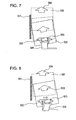
- Fig. 7 shows a typical known structure used for skew correction.
- the structure includes a conveying roller 502 that tries to convey a sheet 505 in a conveying direction 50A and a roller 503 that is disposed so as to face the conveying roller 502 and that is inclined with respect to the conveying direction 50A.
- the inclined roller 503 and the conveying roller 502 convey the sheet 505 while nipping the sheet 505 therebetween.
- a reference surface 501 is provided on a side of a conveying path.
- the reference surface 501 is parallel to the conveying direction 50A and is perpendicular to a plane along which the sheet 505 is conveyed.
- a member including the reference surface 501 has a shape like a wall or a projection so that an edge of the sheet 505 can come into contact with the reference surface 501. Accordingly, the member including the reference surface 501 serves as a guide that defines a reference position in the width direction of the conveying path and that guides the sheet 505 in the conveying direction 50A.
- a skew correction process performed by the above-described structure will be explained below.
- the sheet 505 is conveyed in an inclined orientation
- the sheet 505 is conveyed in an inclined direction by the inclined roller 503.
- the sheet 505 conveyed in the inclined direction comes into contact with the wall that defines the reference position at an edge thereof, and the inclination of the sheet 505 is corrected as the sheet 505 is conveyed. Accordingly, the orientation of the sheet 505 is adjusted such that the edge of the sheet 505 extends along the wall. Since the reference surface 501 is provided to cause the sheet 505 to come into contact therewith, the reference surface 501 is hereafter called a contact surface 501.
- the sheet 505 is conveyed along the contact surface 501. Accordingly, the skew of the sheet 505 is corrected and the position of the sheet 505 in the width direction of the conveying path is determined.
- This structure is simpler and provides higher reliability compared to the case in which the paper feed accuracy is improved.
- Japanese Patent Laid-Open No. 8-208075 discloses a sheet-conveying device including a contact surface fixed at a side of a sheet conveying path, a conveying roller, and an inclined roller, similar to the above-described structure.
- the inclined roller is removed from the position where the inclined roller is in pressure contact with the sheet. Accordingly, the sheet can be conveyed without being influenced by the inclined roller.
- Japanese Patent Laid-Open No. 7-334630 discloses a sheet-conveying device that has a structure similar to the above-described structure but performs a characteristic operation before skew correction. More specifically, a plurality of sensors are provided above a sheet conveying path to detect the amount of inclination of a sheet, and the skew of the sheet is corrected by one of two methods depending on the detected amount of inclination. In a first method, unlike the above-described case, skew correction is performed while an inclined roller is separated from the sheet.
- rollers are arranged at positions spaced from each other in a sheet-conveying direction and the inclination of the sheet is corrected by deflecting the sheet with the rollers such that the leading edge of the sheet comes into contact with a nip portion of the rollers.
- the inclined roller is brought into pressure contact with the sheet and skew correction is performed using the inclined roller and a contact surface, similar to the above-described case.
- the two-way conveyance and rotation of the sheet can be achieved when the width of the conveying path is increased or an additional conveying path is provided so that the sheet can be prevented from coming into contact with the contact surface, the size of the device is increased in such a case.
- the inclined roller when the device is structured such that the inclined roller can move in the vertical direction so that the inclined roller can be separated from the conveying roller, the inclined roller must be supported in a movable manner while the contact surface is fixed to the conveying path. Therefore, as shown in Fig. 8, a supporting member 504 of the inclined roller 503 is deflected when a reaction force is applied from the sheet. Accordingly, the position of the inclined roller 503 is shifted, which degrades the accuracy and reliability of the operation. In order to prevent this deflection, a material with high rigidity must be used.
- an embodiment of the present invention is directed to a sheet-conveying device that allows two-way conveyance and rotation of a sheet on the same conveying path as a conveying path for skew correction of the sheet.
- another embodiment of the present invention is directed to a sheet-conveying device including an inclined roller and a contact surface that are integrated with each other to increase the rigidity thereof so that the accuracy of skew correction can be increased.
- a sheet conveying device as specified in claims 1 to 3.
- a recording apparatus as specified in claims 4 to 10.
- the sheet-conveying device may include a control unit that controls the positions of the inclined-roller-supporting member and the sheet contact member such that the sheet contact member is at the contact position when the inclined-roller-supporting member is at the pressure contact position and the sheet contact member is at the withdrawn position when the inclined-roller-supporting member is at the separate position.
- the inclined-roller-supporting member and the sheet contact member may be integrated with each other.
- the inclined roller and the contact surface can be removed from the conveying path so that conveying operations other than skew correction, such as two-way conveyance and rotation, can be performed on the same conveying path as the conveying path for skew correction without increasing the size of the conveying path. Accordingly, it is not necessary to use a plurality of conveying paths and space can be saved.
- the conveying speed can be increased as a result.
- the reaction force applied from the sheet in the process of skew correction can be canceled. Accordingly, the inclined roller and the contact surface can be prevented from being shifted and the positioning accuracy can be increased.
- the print quality can also be increased.
- the edge portion of the sheet does not come into contact with the contact surface. Accordingly, the edge portion of the sheet is prevented from being bent or deformed and damage of the sheet can be prevented.
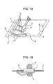
- Figs. 1A and 1B are diagrams illustrating the overall structure according to a first embodiment of the present invention.
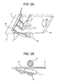
- Figs. 2A and 2B are supplementary diagrams illustrating the overall structure according to first embodiment.
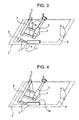
- Fig. 3 is a diagram illustrating a reaction force according to the first embodiment.
- Fig. 4 is a diagram illustrating the overall structure according to a second embodiment of the present invention.
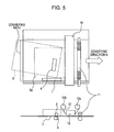
- Fig. 5 is a diagram illustrating the overall structure of a recording apparatus incorporating an embodiment of the present invention.
- Fig. 6 illustrates a circuit block diagram common to the embodiments of the present invention.
- Fig. 7 is a diagram illustrating a typical known structure for skew correction using an inclined roller and a contact surface.
- Fig. 8 is a diagram illustrating the manner in which the inclined roller is shifted due to reaction force in the known structure.
- Fig. 9 is a diagram illustrating the manner in which a sheet comes into contact with the contact surface when the sheet is conveyed in the reverse direction in the known structure.
- Fig. 10 is a diagram illustrating the manner in which the sheet comes into contact with the contact surface when the sheet is rotated in the known structure.
- a sheet-conveying device includes a sheet conveying path along which a sheet is conveyed in a predetermined direction; a conveying roller that is rotatably supported at a position adjacent to the sheet conveying path; an inclined roller that is rotatably supported at a position adjacent to the sheet conveying path so as to face the conveying roller across the sheet conveying path; an inclined-roller-supporting member that supports the inclined roller such that the inclined roller can rotate around a rotational axis that is inclined with respect to a rotational axis of the conveying roller, the inclined-roller-supporting member being capable of moving between a pressure contact position where the inclined roller comes into pressure contact with the conveying roller and a separate position where the inclined roller is separated from the conveying roller; and a sheet contact member having a contact surface with which an edge portion of the sheet conveyed along the sheet conveying path comes into contact, the sheet contact member being capable of moving between a contact position where the contact surface projects into the sheet conveying path
- Figs. 1A and 1B illustrate the overall structure according to a first embodiment.
- Fig. 1A illustrates a perspective view of the structure.
- Fig. 6 illustrates a circuit block diagram common to each of the embodiments.
- a sheet 6 is placed in a sheet conveying path 2, and is conveyed in a conveying direction shown by the arrow A.
- Fig. 1B illustrates a side view of Fig. 1A.
- a contact member 1 that functions as a restricting member has a contact surface 1a and serves a skew correction function similar to that of the known structure.
- the contact member 1 has a shaft 8 that supports the contact member 1 in such a manner that the contact member 1 can rotate around the shaft 8.
- the contact member 1 is placed such that the contact surface 1a is at a contact position where the contact surface 1a interferes with the sheet 6.
- an actuator 115 driving means
- a solenoid rotates the contact member 1 around the shaft 8 in the direction shown by the arrow C in Fig. 2A, so that the contact surface 1a is moved to a withdrawn position below the conveying surface 2 where the contact surface 1a does not interfere with the sheet 6.
- the actuator 115 functions as moving means.
- a conveying roller 3 is rotatably supported at a position adjacent to the sheet conveying path 2, and is rotated by a conveying motor 113 (driving means) to apply a conveying force to the sheet 6.
- An inclined conveying roller 4 is rotatably supported so as to face the conveying roller 3.
- the inclined conveying roller 4 functions as inclined conveying means.
- a rotating shaft of the inclined conveying roller 4 is at an angle with respect to a rotating shaft of the conveying roller 3.
- the inclination angle of the rotating shaft of the inclined conveying roller 4 is set such that an edge of the sheet 6 comes into contact with the contact surface 1a when the sheet 6 is conveyed in an inclined direction.
- the rotating shaft of the inclined conveying roller 4 is supported by supporting members 5 that can be rotated around a shaft 7 by the driving means (not shown) so as to move the inclined conveying roller 4 between a pressure contact position where the inclined conveying roller 4 can come into pressure contact with the conveying roller 3 and a separate position where the inclined conveying roller 4 is separated from the conveying roller 3.
- the sheet 6 enters the conveying path 2 while the contact surface 1a is on the conveying path 2 and the inclined conveying roller 4 is in pressure contact with the conveying roller 3, the sheet 6 is nipped between the conveying roller 3 and the inclined conveying roller 4 and is conveyed in an inclined direction by the conveying force of the conveying roller 3 and the inclined conveying force of the inclined conveying roller 4.
- a side edge thereof gradually approaches the contact surface 1a.
- the sheet 6 is conveyed in the conveying direction A while changing the orientation thereof.
- the orientation of the sheet 6 is adjusted such that the side edge of the sheet 6 extends along the contact surface 1a, and accordingly skew correction and positioning of the sheet 6 in the lateral direction are performed. This operation is similar to that of the above-described known structure.
- an image-recording apparatus in which a sheet is conveyed in opposite directions for printing will be described as an example.
- the sheet 6 is conveyed in the forward and reverse directions along the same conveying path.
- Printing is performed while the sheet 6 is moved in the forward direction and the sheet 6 is simply conveyed when the sheet 6 is moved in the reverse direction.
- the skew correction is performed before printing so that the sheet 6 is oriented straight, and then an image of a first color is printed. Then, the sheet 6 is moved in the reverse direction along the same conveying path, and an image of a second color is printed.
- the inclined conveying roller 4 is moved to the separate position so as to eliminate the influence of the inclined conveying roller 4. If the sheet 6 is slightly shifted in the lateral direction when the sheet 6 is moved in the reverse direction, there is a possibility that the sheet 6 will come into contact with the contact surface 1a (or with an edge of the contact member) and the contact surface 1a will obstruct the movement of the sheet 6. In order to prevent this, when the sheet 6 is moved in the reverse direction, the contact surface 1a is moved to the withdrawn position below the conveying path 2, as shown by the arrow C in Fig. 2A. Accordingly, the sheet 6 can be reliably conveyed even when there is a possibility that the sheet 6 will be slightly shifted when the sheet 6 is moved in the reverse direction.
- the skew correction function can be switched off by moving the contact surface 1a and the inclined conveying roller 4 to the withdrawn position and the separate position, respectively.
- the contact surface 1a and the inclined conveying roller 4 are moved to the withdrawn position and the separate position, respectively, so that the skew correction function is switched off, the sheet 6 can be moved in the opposite directions or rotated in the same conveying path 2. Accordingly, the size of the conveying path 2 can be reduced, which leads to a reduction in the size of the sheet-conveying device.
- Fig. 4 illustrates the structure according to a second embodiment.
- a conveying roller 3, an inclined conveying roller 4, and a conveying surface 2 are similar to those of the first embodiment.
- the second embodiment differs from the first embodiment in that a contact member 1 is integrated with supporting members 5 of the inclined conveying roller 4 and the integrated body is rotatably supported by a shaft 9.
- the shaft 9 is supported such that the solenoid 115 (driving means) can rotate the shaft 9 so as to move the contact surface 1a and the inclined conveying roller 4 to a withdrawn position and a separate position, respectively, at the same time.
- the inclined conveying roller 4 causes the sheet 6 to push the contact surface 1a by a force shown by the arrow F in Fig. 3.
- the inclined conveying roller 4 receives a reaction force shown by the arrow Fr in Fig. 3 from the sheet 6. Accordingly, there is a possibility that the inclined conveying roller 4 will be moved from a predetermined position by the reaction force Fr, and it is necessary to use a material with sufficiently high rigidity to prevent the contact member 1 and the inclined conveying roller 4 from being moved.
- the second embodiment overcomes this disadvantage.
- the contact member 1 and the supporting members 5 of the inclined conveying roller 4 are both fixed to the shaft 9 and are integrated with each other. Therefore, even when the contact member 1 and the inclined conveying roller 4 receive the reaction force from the sheet 6 in the process of skew correction, the reaction force F functions as an internal force in a single rigid body. Accordingly, the positions of the contact surface 1a and the inclined conveying roller 4 can be accurately maintained even when the reaction force is applied from the sheet 6.
- the contact member 1 is integrated with the supporting members 5 of the inclined conveying roller 4, the contact surface 1a and the inclined conveying roller 4 can be moved together with a simple mechanism. Therefore, in addition to the effects obtained by the first embodiment, the skew correction can be performed with high accuracy using a simple mechanism and the skew correction function can be easily switched on and off.
- Fig. 5 illustrates an image-recording apparatus including the structure according to the first embodiment or the second embodiment.
- Fig. 6 illustrates a circuit block diagram.
- reference numeral 110 denotes a central processing unit (CPU) that controls a conveying motor 113, a driving motor 114, an ink sheet motor 12c, an image-forming unit 10, such as a recording head, and the actuator 115.
- reference numeral 111 denotes a read only memory (ROM) that stores control data and the like and reference numeral 112 denotes a random access memory (RAM) that serves as an area for expanding recording data and the like.
- ROM read only memory
- RAM random access memory
- Inks of different colors are successively applied to an ink sheet 12.
- the ink sheet 12 is fed from a feed roller 12b and is wound around a take-up roller 12a that functions as take up means.
- the recording head (thermal head) 10 transfers the ink on the ink sheet 12 onto the sheet 6 by heat.
- a pair of drive rollers 11 convey the sheet 6 in forward and reverse directions. The drive rollers 11 are driven by the driving motor 114 to function as conveying means.
- the sheet 6 is conveyed in the conveying direction A by the conveying roller 3 and the inclined conveying roller 4, and comes into contact with the contact member 1 so that the skew of the sheet 6 is corrected.
- the actuator 115 moves the inclined conveying roller 4 and the contact member 1 in a direction perpendicular to the surface of the sheet 6 (i.e., in the thickness direction of the sheet 6).
- the recording sheet 6 is conveyed in the conveying direction A by the drive rollers 11.
- the ink sheet motor 12c rotates the take-up roller 12a counterclockwise so that the ink sheet 12 is wound around the take-up roller 12a.
- the yellow ink which is the ink of a first color that is applied to the ink sheet 12, is transferred onto the sheet 6 by heating elements that are included in the recording head 10 and that generate heat in accordance with an image signal while the sheet 6 is being moved. Accordingly, a yellow image is formed on the sheet 6.
- the sheet 6 is conveyed by the drive rollers 11 in a direction opposite to the direction A, passes through a region corresponding to the contact member 1, and returns to the recording start position 6a.
- the sheet 6 that returns to the recording start position 6a is moved through a region where the position thereof is restricted by the contact member 1.
- the sheet 6 that returns to the recording start position 6a passes by the contact member 1 or passes through a position where the sheet 6 comes into contact with the contact member 1.
- the contact member 1 is beforehand moved away from the conveying path, the sheet 6 does not come into contact with the contact member 1.
- the ribbon motor 12c drives the take-up roller 12a and winds the ink sheet 12 until a region of magenta, which is a second color, faces the recording head 10. Then, the sheet 6 is conveyed in the conveying direction A by the conveying rollers 11 and a magenta image is formed on the sheet 6 by the recording head 10. Then, a cyan image is similarly transferred onto the sheet 6 and the image-forming operation is finished.
Landscapes
- Engineering & Computer Science (AREA)
- Mechanical Engineering (AREA)
- Microelectronics & Electronic Packaging (AREA)
- General Engineering & Computer Science (AREA)
- Registering Or Overturning Sheets (AREA)
- Delivering By Means Of Belts And Rollers (AREA)
Abstract
Description
- The present invention relates to a sheet-conveying device for conveying a sheet material, such as for example a sheet of paper, an envelope, or a postcard, to an image-forming apparatus, such as a printer and a copy machine.
- In general, many sheet-conveying devices have a skew correction function. When a sheet is skewed, the sheet is conveyed at an angle with respect to a conveying direction of the sheet due to insufficient paper feed accuracy of a sheet-conveying device. In image-forming apparatuses, the skew of the sheet causes paper jams or degradation of print quality. Fig. 7 shows a typical known structure used for skew correction.
- Referring to Fig. 7, the structure includes a
conveying roller 502 that tries to convey asheet 505 in a conveyingdirection 50A and aroller 503 that is disposed so as to face theconveying roller 502 and that is inclined with respect to the conveyingdirection 50A. Theinclined roller 503 and theconveying roller 502 convey thesheet 505 while nipping thesheet 505 therebetween. Areference surface 501 is provided on a side of a conveying path. Thereference surface 501 is parallel to theconveying direction 50A and is perpendicular to a plane along which thesheet 505 is conveyed. A member including thereference surface 501 has a shape like a wall or a projection so that an edge of thesheet 505 can come into contact with thereference surface 501. Accordingly, the member including thereference surface 501 serves as a guide that defines a reference position in the width direction of the conveying path and that guides thesheet 505 in theconveying direction 50A. - A skew correction process performed by the above-described structure will be explained below. When the
sheet 505 is conveyed in an inclined orientation, thesheet 505 is conveyed in an inclined direction by theinclined roller 503. Thesheet 505 conveyed in the inclined direction comes into contact with the wall that defines the reference position at an edge thereof, and the inclination of thesheet 505 is corrected as thesheet 505 is conveyed. Accordingly, the orientation of thesheet 505 is adjusted such that the edge of thesheet 505 extends along the wall. Since thereference surface 501 is provided to cause thesheet 505 to come into contact therewith, thereference surface 501 is hereafter called acontact surface 501. - After the orientation is adjusted, the
sheet 505 is conveyed along thecontact surface 501. Accordingly, the skew of thesheet 505 is corrected and the position of thesheet 505 in the width direction of the conveying path is determined. This structure is simpler and provides higher reliability compared to the case in which the paper feed accuracy is improved. - Two examples of known sheet-conveying devices will be described below with reference to published patent applications. As a first example,
Japanese Patent Laid-Open No. 8-208075 - As a second example,
Japanese Patent Laid-Open No. 7-334630 - In the above-described known devices, it is assumed that the sheet is conveyed in only one direction. In addition, whether or not to perform the skew correction is selected by either bringing the inclined roller into pressure contact with the sheet or separating the inclined roller from the sheet. In addition, the contact surface is fixed to the conveying path. For these reasons, the above-described known devices have the following problems.
- That is, when, for example, the skew correction is not performed and the sheet is conveyed while the inclined roller is separated from the sheet, the width of the conveying path is limited since the contact surface is fixed to the conveying path. Therefore, when the sheet is conveyed in both forward and reverse directions as disclosed in
Japanese Patent Laid-Open No. 2000-326531 Japanese Patent Laid-Open No. 5-213487 contact surface 501 will obstruct the operations other than skew correction. - Accordingly, when the contact surface is fixed to the conveying path as described above, operations other than skew correction, such as two-way conveyance and rotation, cannot be performed.
- Although the two-way conveyance and rotation of the sheet can be achieved when the width of the conveying path is increased or an additional conveying path is provided so that the sheet can be prevented from coming into contact with the contact surface, the size of the device is increased in such a case.
- In addition, when the device is structured such that the inclined roller can move in the vertical direction so that the inclined roller can be separated from the conveying roller, the inclined roller must be supported in a movable manner while the contact surface is fixed to the conveying path. Therefore, as shown in Fig. 8, a supporting
member 504 of theinclined roller 503 is deflected when a reaction force is applied from the sheet. Accordingly, the position of theinclined roller 503 is shifted, which degrades the accuracy and reliability of the operation. In order to prevent this deflection, a material with high rigidity must be used. - In light of the above-described situation, an embodiment of the present invention is directed to a sheet-conveying device that allows two-way conveyance and rotation of a sheet on the same conveying path as a conveying path for skew correction of the sheet. In addition, another embodiment of the present invention is directed to a sheet-conveying device including an inclined roller and a contact surface that are integrated with each other to increase the rigidity thereof so that the accuracy of skew correction can be increased.
- According to a first aspect of the present invention, there is provided a sheet conveying device as specified in
claims 1 to 3. According to a second aspect of the present invention, there is provided a recording apparatus as specified inclaims 4 to 10. - The sheet-conveying device may include a control unit that controls the positions of the inclined-roller-supporting member and the sheet contact member such that the sheet contact member is at the contact position when the inclined-roller-supporting member is at the pressure contact position and the sheet contact member is at the withdrawn position when the inclined-roller-supporting member is at the separate position.
- In addition, the inclined-roller-supporting member and the sheet contact member may be integrated with each other.
- In the above-mentioned sheet-conveying device, the inclined roller and the contact surface can be removed from the conveying path so that conveying operations other than skew correction, such as two-way conveyance and rotation, can be performed on the same conveying path as the conveying path for skew correction without increasing the size of the conveying path. Accordingly, it is not necessary to use a plurality of conveying paths and space can be saved.
- In addition, since the length of the conveying path can be reduced, the conveying speed can be increased as a result. In addition, when the inclined roller and the contact surface are integrated with each other, the reaction force applied from the sheet in the process of skew correction can be canceled. Accordingly, the inclined roller and the contact surface can be prevented from being shifted and the positioning accuracy can be increased.
- Since the positioning accuracy can be increased, the print quality can also be increased. In addition, when the contact surface is completely removed from the conveying path, the edge portion of the sheet does not come into contact with the contact surface. Accordingly, the edge portion of the sheet is prevented from being bent or deformed and damage of the sheet can be prevented.
- Further features of the present invention will become apparent from the following description of exemplary embodiments with reference to the attached drawings.
- Figs. 1A and 1B are diagrams illustrating the overall structure according to a first embodiment of the present invention.
- Figs. 2A and 2B are supplementary diagrams illustrating the overall structure according to first embodiment.
- Fig. 3 is a diagram illustrating a reaction force according to the first embodiment.
- Fig. 4 is a diagram illustrating the overall structure according to a second embodiment of the present invention.
- Fig. 5 is a diagram illustrating the overall structure of a recording apparatus incorporating an embodiment of the present invention.
- Fig. 6 illustrates a circuit block diagram common to the embodiments of the present invention.
- Fig. 7 is a diagram illustrating a typical known structure for skew correction using an inclined roller and a contact surface.
- Fig. 8 is a diagram illustrating the manner in which the inclined roller is shifted due to reaction force in the known structure.
- Fig. 9 is a diagram illustrating the manner in which a sheet comes into contact with the contact surface when the sheet is conveyed in the reverse direction in the known structure.
- Fig. 10 is a diagram illustrating the manner in which the sheet comes into contact with the contact surface when the sheet is rotated in the known structure.
- According to at least one embodiment of the present invention, a sheet-conveying device includes a sheet conveying path along which a sheet is conveyed in a predetermined direction; a conveying roller that is rotatably supported at a position adjacent to the sheet conveying path; an inclined roller that is rotatably supported at a position adjacent to the sheet conveying path so as to face the conveying roller across the sheet conveying path; an inclined-roller-supporting member that supports the inclined roller such that the inclined roller can rotate around a rotational axis that is inclined with respect to a rotational axis of the conveying roller, the inclined-roller-supporting member being capable of moving between a pressure contact position where the inclined roller comes into pressure contact with the conveying roller and a separate position where the inclined roller is separated from the conveying roller; and a sheet contact member having a contact surface with which an edge portion of the sheet conveyed along the sheet conveying path comes into contact, the sheet contact member being capable of moving between a contact position where the contact surface projects into the sheet conveying path so that the edge portion of the sheet can come into contact with the contact surface and a withdrawn position where the contact surface is removed from the sheet conveying path so that the contact surface cannot restrict the position of the edge portion of the sheet.
- Embodiments of the present invention will be described in detail below.
- Figs. 1A and 1B illustrate the overall structure according to a first embodiment. Fig. 1A illustrates a perspective view of the structure. Fig. 6 illustrates a circuit block diagram common to each of the embodiments. A
sheet 6 is placed in asheet conveying path 2, and is conveyed in a conveying direction shown by the arrow A. Fig. 1B illustrates a side view of Fig. 1A. - In Figs. 1A and 1B, a
contact member 1 that functions as a restricting member has acontact surface 1a and serves a skew correction function similar to that of the known structure. In addition, thecontact member 1 has ashaft 8 that supports thecontact member 1 in such a manner that thecontact member 1 can rotate around theshaft 8. When the skew correction is performed, thecontact member 1 is placed such that thecontact surface 1a is at a contact position where thecontact surface 1a interferes with thesheet 6. When the skew correction is not performed, an actuator 115 (driving means), such as a solenoid, rotates thecontact member 1 around theshaft 8 in the direction shown by the arrow C in Fig. 2A, so that thecontact surface 1a is moved to a withdrawn position below the conveyingsurface 2 where thecontact surface 1a does not interfere with thesheet 6. The actuator 115 functions as moving means. - A conveying
roller 3 is rotatably supported at a position adjacent to thesheet conveying path 2, and is rotated by a conveying motor 113 (driving means) to apply a conveying force to thesheet 6. An inclined conveyingroller 4 is rotatably supported so as to face the conveyingroller 3. The inclined conveyingroller 4 functions as inclined conveying means. A rotating shaft of the inclined conveyingroller 4 is at an angle with respect to a rotating shaft of the conveyingroller 3. The inclination angle of the rotating shaft of the inclined conveyingroller 4 is set such that an edge of thesheet 6 comes into contact with thecontact surface 1a when thesheet 6 is conveyed in an inclined direction. The rotating shaft of the inclined conveyingroller 4 is supported by supportingmembers 5 that can be rotated around ashaft 7 by the driving means (not shown) so as to move the inclined conveyingroller 4 between a pressure contact position where the inclined conveyingroller 4 can come into pressure contact with the conveyingroller 3 and a separate position where the inclined conveyingroller 4 is separated from the conveyingroller 3. - Next, the operation of the sheet-conveying device will be described below. When the
sheet 6 enters the conveyingpath 2 while thecontact surface 1a is on the conveyingpath 2 and the inclined conveyingroller 4 is in pressure contact with the conveyingroller 3, thesheet 6 is nipped between the conveyingroller 3 and the inclined conveyingroller 4 and is conveyed in an inclined direction by the conveying force of the conveyingroller 3 and the inclined conveying force of the inclined conveyingroller 4. As thesheet 6 is conveyed in the inclined direction, a side edge thereof gradually approaches thecontact surface 1a. After the side edge of thesheet 6 comes into contact with thecontact surface 1a, thesheet 6 is conveyed in the conveying direction A while changing the orientation thereof. The orientation of thesheet 6 is adjusted such that the side edge of thesheet 6 extends along thecontact surface 1a, and accordingly skew correction and positioning of thesheet 6 in the lateral direction are performed. This operation is similar to that of the above-described known structure. - Next, an image-recording apparatus according to
Japanese Patent Laid-Open No. 2000-326531 sheet 6 is conveyed in the forward and reverse directions along the same conveying path. Printing is performed while thesheet 6 is moved in the forward direction and thesheet 6 is simply conveyed when thesheet 6 is moved in the reverse direction. The skew correction is performed before printing so that thesheet 6 is oriented straight, and then an image of a first color is printed. Then, thesheet 6 is moved in the reverse direction along the same conveying path, and an image of a second color is printed. Since the skew correction is not performed when thesheet 6 is moved in the reverse direction, the inclined conveyingroller 4 is moved to the separate position so as to eliminate the influence of the inclined conveyingroller 4. If thesheet 6 is slightly shifted in the lateral direction when thesheet 6 is moved in the reverse direction, there is a possibility that thesheet 6 will come into contact with thecontact surface 1a (or with an edge of the contact member) and thecontact surface 1a will obstruct the movement of thesheet 6. In order to prevent this, when thesheet 6 is moved in the reverse direction, thecontact surface 1a is moved to the withdrawn position below the conveyingpath 2, as shown by the arrow C in Fig. 2A. Accordingly, thesheet 6 can be reliably conveyed even when there is a possibility that thesheet 6 will be slightly shifted when thesheet 6 is moved in the reverse direction. - Thus, the skew correction function can be switched off by moving the
contact surface 1a and the inclined conveyingroller 4 to the withdrawn position and the separate position, respectively. When thecontact surface 1a and the inclined conveyingroller 4 are moved to the withdrawn position and the separate position, respectively, so that the skew correction function is switched off, thesheet 6 can be moved in the opposite directions or rotated in the same conveyingpath 2. Accordingly, the size of the conveyingpath 2 can be reduced, which leads to a reduction in the size of the sheet-conveying device. - Fig. 4 illustrates the structure according to a second embodiment. In the second embodiment, a conveying
roller 3, an inclined conveyingroller 4, and a conveyingsurface 2 are similar to those of the first embodiment. The second embodiment differs from the first embodiment in that acontact member 1 is integrated with supportingmembers 5 of the inclined conveyingroller 4 and the integrated body is rotatably supported by ashaft 9. Theshaft 9 is supported such that the solenoid 115 (driving means) can rotate theshaft 9 so as to move thecontact surface 1a and the inclined conveyingroller 4 to a withdrawn position and a separate position, respectively, at the same time. - Next, the operation of the sheet-conveying device according to the second embodiment will be described below. Although the processes in which skew correction is performed and not performed are the same as those in the first embodiment, the influence of a reaction force applied from the
sheet 6 when the skew correction is performed is different from that of the first embodiment. - In the first embodiment, the inclined conveying
roller 4 causes thesheet 6 to push thecontact surface 1a by a force shown by the arrow F in Fig. 3. The inclined conveyingroller 4 receives a reaction force shown by the arrow Fr in Fig. 3 from thesheet 6. Accordingly, there is a possibility that the inclined conveyingroller 4 will be moved from a predetermined position by the reaction force Fr, and it is necessary to use a material with sufficiently high rigidity to prevent thecontact member 1 and the inclined conveyingroller 4 from being moved. The second embodiment overcomes this disadvantage. - As shown in Fig. 4, in the second embodiment, the
contact member 1 and the supportingmembers 5 of the inclined conveyingroller 4 are both fixed to theshaft 9 and are integrated with each other. Therefore, even when thecontact member 1 and the inclined conveyingroller 4 receive the reaction force from thesheet 6 in the process of skew correction, the reaction force F functions as an internal force in a single rigid body. Accordingly, the positions of thecontact surface 1a and the inclined conveyingroller 4 can be accurately maintained even when the reaction force is applied from thesheet 6. In addition, since thecontact member 1 is integrated with the supportingmembers 5 of the inclined conveyingroller 4, thecontact surface 1a and the inclined conveyingroller 4 can be moved together with a simple mechanism. Therefore, in addition to the effects obtained by the first embodiment, the skew correction can be performed with high accuracy using a simple mechanism and the skew correction function can be easily switched on and off. - Fig. 5 illustrates an image-recording apparatus including the structure according to the first embodiment or the second embodiment.
- Fig. 6 illustrates a circuit block diagram. In Fig. 6,
reference numeral 110 denotes a central processing unit (CPU) that controls a conveyingmotor 113, a drivingmotor 114, anink sheet motor 12c, an image-formingunit 10, such as a recording head, and theactuator 115. In addition,reference numeral 111 denotes a read only memory (ROM) that stores control data and the like andreference numeral 112 denotes a random access memory (RAM) that serves as an area for expanding recording data and the like. - Inks of different colors, such as yellow, magenta, and cyan, are successively applied to an
ink sheet 12. Theink sheet 12 is fed from afeed roller 12b and is wound around a take-uproller 12a that functions as take up means. The recording head (thermal head) 10 transfers the ink on theink sheet 12 onto thesheet 6 by heat. A pair ofdrive rollers 11 convey thesheet 6 in forward and reverse directions. Thedrive rollers 11 are driven by the drivingmotor 114 to function as conveying means. - The
sheet 6 is conveyed in the conveying direction A by the conveyingroller 3 and the inclined conveyingroller 4, and comes into contact with thecontact member 1 so that the skew of thesheet 6 is corrected. When thesheet 6 is nipped between thedrive rollers 11 after the skew correction, theactuator 115 moves the inclined conveyingroller 4 and thecontact member 1 in a direction perpendicular to the surface of the sheet 6 (i.e., in the thickness direction of the sheet 6). After the inclined conveyingroller 4 and thecontact member 1 are moved to positions where they do not come into contact with thesheet 6, therecording sheet 6 is conveyed in the conveying direction A by thedrive rollers 11. At the same time, theink sheet motor 12c rotates the take-uproller 12a counterclockwise so that theink sheet 12 is wound around the take-uproller 12a. - Then, image recording is started when the
sheet 6 reaches arecording start position 6a. More specifically, the yellow ink, which is the ink of a first color that is applied to theink sheet 12, is transferred onto thesheet 6 by heating elements that are included in therecording head 10 and that generate heat in accordance with an image signal while thesheet 6 is being moved. Accordingly, a yellow image is formed on thesheet 6. - After the image of the first color is formed, the
sheet 6 is conveyed by thedrive rollers 11 in a direction opposite to the direction A, passes through a region corresponding to thecontact member 1, and returns to therecording start position 6a. Thus, thesheet 6 that returns to therecording start position 6a is moved through a region where the position thereof is restricted by thecontact member 1. In other words, thesheet 6 that returns to therecording start position 6a passes by thecontact member 1 or passes through a position where thesheet 6 comes into contact with thecontact member 1. However, since thecontact member 1 is beforehand moved away from the conveying path, thesheet 6 does not come into contact with thecontact member 1. Theribbon motor 12c drives the take-uproller 12a and winds theink sheet 12 until a region of magenta, which is a second color, faces therecording head 10. Then, thesheet 6 is conveyed in the conveying direction A by the conveyingrollers 11 and a magenta image is formed on thesheet 6 by therecording head 10. Then, a cyan image is similarly transferred onto thesheet 6 and the image-forming operation is finished. - While the present invention has been described with reference to exemplary embodiments, it is to be understood that the invention is not limited to the disclosed exemplary embodiments. The scope of the following claims is to be accorded the broadest interpretation so as to encompass all modifications, equivalent structures and functions.
Claims (10)
- A sheet-conveying device comprising:a sheet conveying path (2) along which a sheet is conveyed in a predetermined direction in use;a conveying roller (3) that is rotatably supported at a position adjacent the sheet conveying path;an inclined roller (4) that is rotatably supported at a position adjacent the sheet conveying path so as to face the conveying roller across the sheet conveying path;an inclined-roller-supporting member (5, 7) that supports the inclined roller such that the inclined roller can rotate about a rotational axis that is inclined with respect to a rotational axis of the conveying roller, the inclined-roller-supporting member being capable of moving between a pressure contact position where the inclined roller comes into pressure contact with the conveying roller and a separate position where the inclined roller is separated from the conveying roller; anda sheet contact member (1) having a contact surface (1a) with which an edge portion of a sheet conveyed along the sheet conveying path comes into contact, characterized in that the sheet contact member is moveable between a contact position where the contact surface projects into the sheet conveying path so that an edge portion of a sheet can come into contact with the contact surface in use, and a withdrawn position where the contact surface is removed from the sheet conveying path so that the contact surface cannot restrict the position of the edge portion of the sheet.
- The sheet-conveying device according to claim 1, further comprising:control means (110) for controlling the positions of the inclined-roller-supporting member and the sheet contact member, such that the sheet contact member is at the contact position when the inclined-roller-supporting member is at the pressure contact position and the sheet contact member is at the withdrawn position when the inclined-roller-supporting member is at the separate position.
- The sheet-conveying device according to claim 1 or claim 2, wherein the inclined-roller-supporting member and the sheet contact member are integrated with each other.
- A recording apparatus comprising:a sheet conveying device as claimed in any preceding claim;two-way conveying means (11) that is positioned downstream of the sheet conveying means for conveying the sheet on the conveying path in opposite directions;a recording head (10) that records on the sheet conveyed in the opposite directions by the two-way conveying means by transferring a plurality of kinds of ink onto the sheet;moving means (8) that moves the sheet contact member to a withdrawn position where the sheet does not come into contact with the sheet contact member when the two-way conveying means conveys the sheet in the opposite directions.
- The recording apparatus according to claim 4,
wherein the moving means moves the sheet contact member in the thickness direction of the sheet on the sheet conveying path. - The recording apparatus according to claim 4,
wherein the inclined roller moves to a position where the sheet does not come into contact with the inclined roller when the sheet contact member is moved to the withdrawn position. - The recording apparatus according to any one of claims 4 to 6, further comprising take-up means (12) that winds the ink sheet.
- The recording apparatus according to any one of claims 4 to 7, wherein the two-way conveying means includes a pair of rollers that convey the sheet while nipping the sheet between the rollers.
- The recording apparatus according to any one of claims 4 to 8, wherein the recording head records on the sheet when the sheet is conveyed downstream by the two-way conveying means.
- The recording apparatus according to any one of claims 4 to 9, wherein a region in which the sheet is conveyed in the opposite directions by the two-way conveying means includes a region corresponding to the sheet contact member.
Applications Claiming Priority (1)
| Application Number | Priority Date | Filing Date | Title |
|---|---|---|---|
| JP2005080776A JP4590288B2 (en) | 2005-03-22 | 2005-03-22 | Sheet transport device |
Publications (2)
| Publication Number | Publication Date |
|---|---|
| EP1705140A1 true EP1705140A1 (en) | 2006-09-27 |
| EP1705140B1 EP1705140B1 (en) | 2008-09-10 |
Family
ID=36331247
Family Applications (1)
| Application Number | Title | Priority Date | Filing Date |
|---|---|---|---|
| EP06251115A Expired - Lifetime EP1705140B1 (en) | 2005-03-22 | 2006-03-01 | Recording apparatus with a two-way conveying means and a skew correction means |
Country Status (8)
| Country | Link |
|---|---|
| US (1) | US7441772B2 (en) |
| EP (1) | EP1705140B1 (en) |
| JP (1) | JP4590288B2 (en) |
| KR (1) | KR100810181B1 (en) |
| CN (1) | CN100569606C (en) |
| AT (1) | ATE407904T1 (en) |
| DE (1) | DE602006002630D1 (en) |
| TW (1) | TWI294353B (en) |
Cited By (2)
| Publication number | Priority date | Publication date | Assignee | Title |
|---|---|---|---|---|
| EP1842813A3 (en) * | 2006-04-07 | 2011-03-02 | Canon Kabushiki Kaisha | Sheet conveying apparatus and image forming apparatus equipped therewith |
| ITTO20100333A1 (en) * | 2010-04-21 | 2011-10-22 | Panini Spa | DOCUMENT SUPPLY DEVICE, IN PARTICULAR BANK AND SIMILAR CHECKS, FOR A TREATMENT APPLIANCE AS A SCANNER |
Families Citing this family (13)
| Publication number | Priority date | Publication date | Assignee | Title |
|---|---|---|---|---|
| US7648138B2 (en) * | 2004-09-14 | 2010-01-19 | Hitachi-Omron Terminal Solutions, Corp. | Sheet handling apparatus |
| JP2009020612A (en) * | 2007-07-10 | 2009-01-29 | Toshiba Tec Corp | Medium processing apparatus and medium processing method |
| JP4991465B2 (en) * | 2007-09-25 | 2012-08-01 | キヤノン株式会社 | Image forming apparatus and image forming method |
| US7926806B2 (en) * | 2008-02-25 | 2011-04-19 | Lexmark International, Inc. | Systems for aligning a media sheet in an image forming apparatus |
| KR200454726Y1 (en) * | 2009-05-04 | 2011-07-28 | 조연규 | Doubling Roller |
| CN102529429B (en) * | 2010-12-31 | 2014-07-23 | 泰金宝电通股份有限公司 | Paper feeding device and business machine |
| JP2012214294A (en) * | 2011-03-28 | 2012-11-08 | Canon Inc | Sheet conveying device for separating multi-fed sheets, and image reading apparatus |
| JP5849511B2 (en) * | 2011-08-11 | 2016-01-27 | セイコーエプソン株式会社 | Conveying device and printing device |
| CN102951465B (en) * | 2012-10-26 | 2015-06-17 | 天津长荣印刷设备股份有限公司 | Belt correction device and working method thereof |
| CN103332018B (en) * | 2013-04-19 | 2015-06-10 | 苏州市华中文具有限公司 | Printer for printing characters on surfaces of pencils |
| JP6494415B2 (en) * | 2015-05-19 | 2019-04-03 | キヤノン株式会社 | Sheet processing device |
| US11542086B2 (en) | 2018-08-06 | 2023-01-03 | Better Packages, Inc. | Packaging apparatus for film inflation and method thereof |
| JP7436539B2 (en) * | 2022-02-28 | 2024-02-21 | 日本金銭機械株式会社 | Conveyance guide drive mechanism, sheet conveyance device, control method for sheet conveyance device, and sheet handling device |
Citations (9)
| Publication number | Priority date | Publication date | Assignee | Title |
|---|---|---|---|---|
| JPS58139944A (en) * | 1982-02-13 | 1983-08-19 | Canon Inc | Paper feeding device |
| JPS60102351A (en) * | 1983-11-09 | 1985-06-06 | Fuji Xerox Co Ltd | Aslant advance correcting apparatus for paper sheet |
| US4668961A (en) * | 1984-04-20 | 1987-05-26 | Canon Kabushiki Kaisha | Recording apparatus |
| US4676498A (en) * | 1982-12-10 | 1987-06-30 | Canon Kabushiki Kaisha | Sheet feeding apparatus |
| JPH0239968A (en) * | 1988-07-29 | 1990-02-08 | Canon Inc | Image recording device |
| US5742318A (en) * | 1989-05-08 | 1998-04-21 | Canon Kabushiki Kaisha | Recording apparatus |
| JP2002362785A (en) * | 2001-06-04 | 2002-12-18 | Canon Inc | Sheet conveying apparatus and image forming apparatus having the same |
| JP2003165652A (en) * | 2001-11-30 | 2003-06-10 | Canon Inc | Sheet conveying apparatus and image forming apparatus having the same |
| JP2003312898A (en) * | 2002-04-17 | 2003-11-06 | Hitachi Ltd | Paper handling equipment |
Family Cites Families (20)
| Publication number | Priority date | Publication date | Assignee | Title |
|---|---|---|---|---|
| US4266762A (en) * | 1979-08-29 | 1981-05-12 | Xerox Corporation | Sheet alignment and feeding apparatus |
| JPS58183550A (en) * | 1982-04-20 | 1983-10-26 | Canon Inc | Sheet feed alignment device |
| JPS58216852A (en) * | 1982-06-09 | 1983-12-16 | Canon Inc | Sheet conveyance device |
| US5162857A (en) * | 1987-07-14 | 1992-11-10 | Canon Kabushiki Kaisha | Sheet conveyer having a sheet aligner |
| JPH01314180A (en) * | 1988-06-14 | 1989-12-19 | Nikon Corp | image recording device |
| US5120047A (en) * | 1991-02-07 | 1992-06-09 | Xerox Corporation | Integral sheet stacking buckle suppressor and registration edge |
| US5169140A (en) * | 1991-11-25 | 1992-12-08 | Xerox Corporation | Method and apparatus for deskewing and side registering a sheet |
| US5253862A (en) * | 1991-12-23 | 1993-10-19 | Xerox Corporation | Adjustable normal force edge registering apparatus |
| JP3149139B2 (en) | 1992-02-06 | 2001-03-26 | 株式会社リコー | Paper feeder |
| JPH07334630A (en) | 1994-06-08 | 1995-12-22 | Hitachi Ltd | Form tilt correction mechanism |
| JPH08208075A (en) | 1995-01-31 | 1996-08-13 | Glory Ltd | Aligned delivery device for paper sheet |
| JP3517485B2 (en) * | 1995-07-11 | 2004-04-12 | キヤノン株式会社 | Sheet material conveying means and image forming apparatus |
| JP3747127B2 (en) * | 1997-07-28 | 2006-02-22 | キヤノン株式会社 | Manufacturing method of color filter, manufacturing method of display device, and manufacturing method of information processing device including display device |
| US6574011B1 (en) * | 1997-10-27 | 2003-06-03 | Canon Kabushiki Kaisha | Image formation apparatus |
| JP2000326531A (en) | 1999-05-19 | 2000-11-28 | Canon Inc | Recording sheet and thermal transfer recording device |
| US6561504B2 (en) * | 2001-03-30 | 2003-05-13 | Lexmark International, Inc. | Finisher with single roller for frictionally moving each sheet |
| JP2004284741A (en) * | 2003-03-20 | 2004-10-14 | Fuji Xerox Co Ltd | Sheet transport device and sheet handling device equipped with it |
| JP4385627B2 (en) * | 2003-03-24 | 2009-12-16 | 富士ゼロックス株式会社 | Sheet conveying apparatus and sheet processing apparatus using the same |
| US7648138B2 (en) * | 2004-09-14 | 2010-01-19 | Hitachi-Omron Terminal Solutions, Corp. | Sheet handling apparatus |
| JP4708900B2 (en) * | 2005-07-28 | 2011-06-22 | キヤノン株式会社 | Sheet conveying apparatus and image forming apparatus |
-
2005
- 2005-03-22 JP JP2005080776A patent/JP4590288B2/en not_active Expired - Fee Related
-
2006
- 2006-02-24 TW TW095106461A patent/TWI294353B/en not_active IP Right Cessation
- 2006-03-01 EP EP06251115A patent/EP1705140B1/en not_active Expired - Lifetime
- 2006-03-01 DE DE602006002630T patent/DE602006002630D1/en not_active Expired - Lifetime
- 2006-03-01 AT AT06251115T patent/ATE407904T1/en not_active IP Right Cessation
- 2006-03-16 US US11/376,822 patent/US7441772B2/en not_active Expired - Fee Related
- 2006-03-21 KR KR1020060025494A patent/KR100810181B1/en not_active Expired - Fee Related
- 2006-03-22 CN CNB2006100655719A patent/CN100569606C/en not_active Expired - Fee Related
Patent Citations (9)
| Publication number | Priority date | Publication date | Assignee | Title |
|---|---|---|---|---|
| JPS58139944A (en) * | 1982-02-13 | 1983-08-19 | Canon Inc | Paper feeding device |
| US4676498A (en) * | 1982-12-10 | 1987-06-30 | Canon Kabushiki Kaisha | Sheet feeding apparatus |
| JPS60102351A (en) * | 1983-11-09 | 1985-06-06 | Fuji Xerox Co Ltd | Aslant advance correcting apparatus for paper sheet |
| US4668961A (en) * | 1984-04-20 | 1987-05-26 | Canon Kabushiki Kaisha | Recording apparatus |
| JPH0239968A (en) * | 1988-07-29 | 1990-02-08 | Canon Inc | Image recording device |
| US5742318A (en) * | 1989-05-08 | 1998-04-21 | Canon Kabushiki Kaisha | Recording apparatus |
| JP2002362785A (en) * | 2001-06-04 | 2002-12-18 | Canon Inc | Sheet conveying apparatus and image forming apparatus having the same |
| JP2003165652A (en) * | 2001-11-30 | 2003-06-10 | Canon Inc | Sheet conveying apparatus and image forming apparatus having the same |
| JP2003312898A (en) * | 2002-04-17 | 2003-11-06 | Hitachi Ltd | Paper handling equipment |
Non-Patent Citations (6)
| Title |
|---|
| PATENT ABSTRACTS OF JAPAN vol. 007, no. 257 (M - 256) 16 November 1983 (1983-11-16) * |
| PATENT ABSTRACTS OF JAPAN vol. 009, no. 252 (M - 420) 9 October 1985 (1985-10-09) * |
| PATENT ABSTRACTS OF JAPAN vol. 014, no. 198 (M - 0965) 23 April 1990 (1990-04-23) * |
| PATENT ABSTRACTS OF JAPAN vol. 2003, no. 04 2 April 2003 (2003-04-02) * |
| PATENT ABSTRACTS OF JAPAN vol. 2003, no. 10 8 October 2003 (2003-10-08) * |
| PATENT ABSTRACTS OF JAPAN vol. 2003, no. 12 5 December 2003 (2003-12-05) * |
Cited By (2)
| Publication number | Priority date | Publication date | Assignee | Title |
|---|---|---|---|---|
| EP1842813A3 (en) * | 2006-04-07 | 2011-03-02 | Canon Kabushiki Kaisha | Sheet conveying apparatus and image forming apparatus equipped therewith |
| ITTO20100333A1 (en) * | 2010-04-21 | 2011-10-22 | Panini Spa | DOCUMENT SUPPLY DEVICE, IN PARTICULAR BANK AND SIMILAR CHECKS, FOR A TREATMENT APPLIANCE AS A SCANNER |
Also Published As
| Publication number | Publication date |
|---|---|
| CN1837000A (en) | 2006-09-27 |
| EP1705140B1 (en) | 2008-09-10 |
| TW200642852A (en) | 2006-12-16 |
| CN100569606C (en) | 2009-12-16 |
| ATE407904T1 (en) | 2008-09-15 |
| US7441772B2 (en) | 2008-10-28 |
| KR100810181B1 (en) | 2008-03-07 |
| TWI294353B (en) | 2008-03-11 |
| KR20060102285A (en) | 2006-09-27 |
| DE602006002630D1 (en) | 2008-10-23 |
| US20060214363A1 (en) | 2006-09-28 |
| JP2006264793A (en) | 2006-10-05 |
| JP4590288B2 (en) | 2010-12-01 |
Similar Documents
| Publication | Publication Date | Title |
|---|---|---|
| US7441772B2 (en) | Sheet-conveying device | |
| US8376543B2 (en) | Recording apparatus and sheet processing method | |
| JP2007297210A (en) | Sheet conveying apparatus and image forming apparatus provided with the same | |
| US7549635B2 (en) | Paper conveyance apparatus and image recording apparatus | |
| JP2005200183A (en) | Carrying device and image recorder | |
| US8840104B2 (en) | Printing apparatus and sheet handling apparatus | |
| US12166944B2 (en) | Image recording device, method of controlling image recording device, and non-transitory computer-readable recording medium therefor | |
| JP2007276922A (en) | Printer paper transport device | |
| JP4577426B2 (en) | Image recording device | |
| JP3802380B2 (en) | Printer | |
| JP4193072B2 (en) | Recording medium conveying apparatus, recording apparatus, and liquid ejecting apparatus | |
| JP4343036B2 (en) | Printer | |
| JP4475169B2 (en) | Sheet conveying apparatus and printer | |
| JP7349065B2 (en) | Post-processing system and image forming system | |
| JP4561999B2 (en) | RECORDED MEDIUM CONVEYING DEVICE, RECORDING DEVICE, RECORDING DEVICE MANUFACTURING METHOD, LIQUID EJECTING DEVICE | |
| JP4585593B2 (en) | Image recording device | |
| JPH11227978A (en) | Sheet processing device and recording device | |
| US20060092255A1 (en) | Image recording apparatus and sheet material transporting apparatus | |
| JP2009113265A (en) | Recording device | |
| JP2001158555A (en) | Paper transport mechanism in thermal printer | |
| JP5173343B2 (en) | Recording device | |
| JP6858571B2 (en) | Paper tension control mechanism and printer | |
| JP2006044149A (en) | Ink-jet recording device | |
| JP6732462B2 (en) | Recording apparatus and method for controlling recording apparatus | |
| JP5142815B2 (en) | Printing device |
Legal Events
| Date | Code | Title | Description |
|---|---|---|---|
| PUAI | Public reference made under article 153(3) epc to a published international application that has entered the european phase |
Free format text: ORIGINAL CODE: 0009012 |
|
| AK | Designated contracting states |
Kind code of ref document: A1 Designated state(s): AT BE BG CH CY CZ DE DK EE ES FI FR GB GR HU IE IS IT LI LT LU LV MC NL PL PT RO SE SI SK TR |
|
| AX | Request for extension of the european patent |
Extension state: AL BA HR MK YU |
|
| 17P | Request for examination filed |
Effective date: 20070327 |
|
| AKX | Designation fees paid |
Designated state(s): AT BE BG CH CY CZ DE DK EE ES FI FR GB GR HU IE IS IT LI LT LU LV MC NL PL PT RO SE SI SK TR |
|
| GRAP | Despatch of communication of intention to grant a patent |
Free format text: ORIGINAL CODE: EPIDOSNIGR1 |
|
| RTI1 | Title (correction) |
Free format text: RECORDING APPARATUS WITH A TWO-WAY CONVEYING MEANS AND A SKEW CORRECTION MEANS |
|
| GRAS | Grant fee paid |
Free format text: ORIGINAL CODE: EPIDOSNIGR3 |
|
| GRAA | (expected) grant |
Free format text: ORIGINAL CODE: 0009210 |
|
| AK | Designated contracting states |
Kind code of ref document: B1 Designated state(s): AT BE BG CH CY CZ DE DK EE ES FI FR GB GR HU IE IS IT LI LT LU LV MC NL PL PT RO SE SI SK TR |
|
| REG | Reference to a national code |
Ref country code: GB Ref legal event code: FG4D |
|
| REG | Reference to a national code |
Ref country code: CH Ref legal event code: EP |
|
| REG | Reference to a national code |
Ref country code: IE Ref legal event code: FG4D |
|
| REF | Corresponds to: |
Ref document number: 602006002630 Country of ref document: DE Date of ref document: 20081023 Kind code of ref document: P |
|
| PG25 | Lapsed in a contracting state [announced via postgrant information from national office to epo] |
Ref country code: LT Free format text: LAPSE BECAUSE OF FAILURE TO SUBMIT A TRANSLATION OF THE DESCRIPTION OR TO PAY THE FEE WITHIN THE PRESCRIBED TIME-LIMIT Effective date: 20080910 |
|
| PG25 | Lapsed in a contracting state [announced via postgrant information from national office to epo] |
Ref country code: SI Free format text: LAPSE BECAUSE OF FAILURE TO SUBMIT A TRANSLATION OF THE DESCRIPTION OR TO PAY THE FEE WITHIN THE PRESCRIBED TIME-LIMIT Effective date: 20080910 Ref country code: LV Free format text: LAPSE BECAUSE OF FAILURE TO SUBMIT A TRANSLATION OF THE DESCRIPTION OR TO PAY THE FEE WITHIN THE PRESCRIBED TIME-LIMIT Effective date: 20080910 Ref country code: FI Free format text: LAPSE BECAUSE OF FAILURE TO SUBMIT A TRANSLATION OF THE DESCRIPTION OR TO PAY THE FEE WITHIN THE PRESCRIBED TIME-LIMIT Effective date: 20080910 Ref country code: AT Free format text: LAPSE BECAUSE OF FAILURE TO SUBMIT A TRANSLATION OF THE DESCRIPTION OR TO PAY THE FEE WITHIN THE PRESCRIBED TIME-LIMIT Effective date: 20080910 |
|
| NLV1 | Nl: lapsed or annulled due to failure to fulfill the requirements of art. 29p and 29m of the patents act | ||
| PG25 | Lapsed in a contracting state [announced via postgrant information from national office to epo] |
Ref country code: BE Free format text: LAPSE BECAUSE OF FAILURE TO SUBMIT A TRANSLATION OF THE DESCRIPTION OR TO PAY THE FEE WITHIN THE PRESCRIBED TIME-LIMIT Effective date: 20080910 |
|
| PG25 | Lapsed in a contracting state [announced via postgrant information from national office to epo] |
Ref country code: ES Free format text: LAPSE BECAUSE OF FAILURE TO SUBMIT A TRANSLATION OF THE DESCRIPTION OR TO PAY THE FEE WITHIN THE PRESCRIBED TIME-LIMIT Effective date: 20081221 Ref country code: BG Free format text: LAPSE BECAUSE OF FAILURE TO SUBMIT A TRANSLATION OF THE DESCRIPTION OR TO PAY THE FEE WITHIN THE PRESCRIBED TIME-LIMIT Effective date: 20081210 |
|
| PG25 | Lapsed in a contracting state [announced via postgrant information from national office to epo] |
Ref country code: IS Free format text: LAPSE BECAUSE OF FAILURE TO SUBMIT A TRANSLATION OF THE DESCRIPTION OR TO PAY THE FEE WITHIN THE PRESCRIBED TIME-LIMIT Effective date: 20090110 Ref country code: PT Free format text: LAPSE BECAUSE OF FAILURE TO SUBMIT A TRANSLATION OF THE DESCRIPTION OR TO PAY THE FEE WITHIN THE PRESCRIBED TIME-LIMIT Effective date: 20090210 Ref country code: SK Free format text: LAPSE BECAUSE OF FAILURE TO SUBMIT A TRANSLATION OF THE DESCRIPTION OR TO PAY THE FEE WITHIN THE PRESCRIBED TIME-LIMIT Effective date: 20080910 Ref country code: RO Free format text: LAPSE BECAUSE OF FAILURE TO SUBMIT A TRANSLATION OF THE DESCRIPTION OR TO PAY THE FEE WITHIN THE PRESCRIBED TIME-LIMIT Effective date: 20080910 Ref country code: CZ Free format text: LAPSE BECAUSE OF FAILURE TO SUBMIT A TRANSLATION OF THE DESCRIPTION OR TO PAY THE FEE WITHIN THE PRESCRIBED TIME-LIMIT Effective date: 20080910 Ref country code: NL Free format text: LAPSE BECAUSE OF FAILURE TO SUBMIT A TRANSLATION OF THE DESCRIPTION OR TO PAY THE FEE WITHIN THE PRESCRIBED TIME-LIMIT Effective date: 20080910 |
|
| PLBE | No opposition filed within time limit |
Free format text: ORIGINAL CODE: 0009261 |
|
| STAA | Information on the status of an ep patent application or granted ep patent |
Free format text: STATUS: NO OPPOSITION FILED WITHIN TIME LIMIT |
|
| PG25 | Lapsed in a contracting state [announced via postgrant information from national office to epo] |
Ref country code: DK Free format text: LAPSE BECAUSE OF FAILURE TO SUBMIT A TRANSLATION OF THE DESCRIPTION OR TO PAY THE FEE WITHIN THE PRESCRIBED TIME-LIMIT Effective date: 20080910 Ref country code: EE Free format text: LAPSE BECAUSE OF FAILURE TO SUBMIT A TRANSLATION OF THE DESCRIPTION OR TO PAY THE FEE WITHIN THE PRESCRIBED TIME-LIMIT Effective date: 20080910 |
|
| 26N | No opposition filed |
Effective date: 20090611 |
|
| PG25 | Lapsed in a contracting state [announced via postgrant information from national office to epo] |
Ref country code: IT Free format text: LAPSE BECAUSE OF FAILURE TO SUBMIT A TRANSLATION OF THE DESCRIPTION OR TO PAY THE FEE WITHIN THE PRESCRIBED TIME-LIMIT Effective date: 20080910 |
|
| PG25 | Lapsed in a contracting state [announced via postgrant information from national office to epo] |
Ref country code: MC Free format text: LAPSE BECAUSE OF NON-PAYMENT OF DUE FEES Effective date: 20090331 |
|
| REG | Reference to a national code |
Ref country code: FR Ref legal event code: ST Effective date: 20091130 |
|
| PG25 | Lapsed in a contracting state [announced via postgrant information from national office to epo] |
Ref country code: IE Free format text: LAPSE BECAUSE OF NON-PAYMENT OF DUE FEES Effective date: 20090301 Ref country code: SE Free format text: LAPSE BECAUSE OF FAILURE TO SUBMIT A TRANSLATION OF THE DESCRIPTION OR TO PAY THE FEE WITHIN THE PRESCRIBED TIME-LIMIT Effective date: 20081210 |
|
| PG25 | Lapsed in a contracting state [announced via postgrant information from national office to epo] |
Ref country code: FR Free format text: LAPSE BECAUSE OF NON-PAYMENT OF DUE FEES Effective date: 20091123 |
|
| PG25 | Lapsed in a contracting state [announced via postgrant information from national office to epo] |
Ref country code: PL Free format text: LAPSE BECAUSE OF FAILURE TO SUBMIT A TRANSLATION OF THE DESCRIPTION OR TO PAY THE FEE WITHIN THE PRESCRIBED TIME-LIMIT Effective date: 20080910 |
|
| PG25 | Lapsed in a contracting state [announced via postgrant information from national office to epo] |
Ref country code: GR Free format text: LAPSE BECAUSE OF FAILURE TO SUBMIT A TRANSLATION OF THE DESCRIPTION OR TO PAY THE FEE WITHIN THE PRESCRIBED TIME-LIMIT Effective date: 20081211 |
|
| REG | Reference to a national code |
Ref country code: CH Ref legal event code: PL |
|
| PG25 | Lapsed in a contracting state [announced via postgrant information from national office to epo] |
Ref country code: LI Free format text: LAPSE BECAUSE OF NON-PAYMENT OF DUE FEES Effective date: 20100331 Ref country code: CH Free format text: LAPSE BECAUSE OF NON-PAYMENT OF DUE FEES Effective date: 20100331 |
|
| PG25 | Lapsed in a contracting state [announced via postgrant information from national office to epo] |
Ref country code: LU Free format text: LAPSE BECAUSE OF NON-PAYMENT OF DUE FEES Effective date: 20090301 |
|
| PG25 | Lapsed in a contracting state [announced via postgrant information from national office to epo] |
Ref country code: HU Free format text: LAPSE BECAUSE OF FAILURE TO SUBMIT A TRANSLATION OF THE DESCRIPTION OR TO PAY THE FEE WITHIN THE PRESCRIBED TIME-LIMIT Effective date: 20090311 |
|
| PG25 | Lapsed in a contracting state [announced via postgrant information from national office to epo] |
Ref country code: TR Free format text: LAPSE BECAUSE OF FAILURE TO SUBMIT A TRANSLATION OF THE DESCRIPTION OR TO PAY THE FEE WITHIN THE PRESCRIBED TIME-LIMIT Effective date: 20080910 |
|
| PG25 | Lapsed in a contracting state [announced via postgrant information from national office to epo] |
Ref country code: CY Free format text: LAPSE BECAUSE OF FAILURE TO SUBMIT A TRANSLATION OF THE DESCRIPTION OR TO PAY THE FEE WITHIN THE PRESCRIBED TIME-LIMIT Effective date: 20080910 |
|
| PGFP | Annual fee paid to national office [announced via postgrant information from national office to epo] |
Ref country code: GB Payment date: 20150316 Year of fee payment: 10 |
|
| PGFP | Annual fee paid to national office [announced via postgrant information from national office to epo] |
Ref country code: DE Payment date: 20150331 Year of fee payment: 10 |
|
| REG | Reference to a national code |
Ref country code: DE Ref legal event code: R119 Ref document number: 602006002630 Country of ref document: DE |
|
| GBPC | Gb: european patent ceased through non-payment of renewal fee |
Effective date: 20160301 |
|
| PG25 | Lapsed in a contracting state [announced via postgrant information from national office to epo] |
Ref country code: GB Free format text: LAPSE BECAUSE OF NON-PAYMENT OF DUE FEES Effective date: 20160301 Ref country code: DE Free format text: LAPSE BECAUSE OF NON-PAYMENT OF DUE FEES Effective date: 20161001 |