EP1704945A1 - Ejectorsystem for moulds - Google Patents
Ejectorsystem for moulds Download PDFInfo
- Publication number
- EP1704945A1 EP1704945A1 EP06100051A EP06100051A EP1704945A1 EP 1704945 A1 EP1704945 A1 EP 1704945A1 EP 06100051 A EP06100051 A EP 06100051A EP 06100051 A EP06100051 A EP 06100051A EP 1704945 A1 EP1704945 A1 EP 1704945A1
- Authority
- EP
- European Patent Office
- Prior art keywords
- ejector
- plate
- chamber
- middle plate
- ejector system
- Prior art date
- Legal status (The legal status is an assumption and is not a legal conclusion. Google has not performed a legal analysis and makes no representation as to the accuracy of the status listed.)
- Withdrawn
Links
Images

Classifications
-
- B—PERFORMING OPERATIONS; TRANSPORTING
- B22—CASTING; POWDER METALLURGY
- B22C—FOUNDRY MOULDING
- B22C7/00—Patterns; Manufacture thereof so far as not provided for in other classes
- B22C7/06—Core boxes
- B22C7/067—Ejector elements
-
- B—PERFORMING OPERATIONS; TRANSPORTING
- B22—CASTING; POWDER METALLURGY
- B22C—FOUNDRY MOULDING
- B22C17/00—Moulding machines characterised by the mechanism for separating the pattern from the mould or for turning over the flask or the pattern plate
- B22C17/02—Moulding machines with pin lifting arrangement
Definitions
- the invention relates to an ejector system for molding boxes, in particular core boxes.
- Such systems are known and may be permanently associated with the molding box to expel the molding formed by injection or the like of corresponding molding material from the mold.
- the ejection movement can be done by pressure medium or a mechanical movement drive.
- the system comprises a rigid frame, preferably of metal, on which a mold-facing tool base, e.g. is mounted in plastic, while in the frame a movable in the axial direction, on the one hand by the ejection pulse and on the other hand of return springs against a rest position determining attacks acted support member for the actual ejector part is arranged.
- the latter has a projecting through a guide bore of the lower tool part shank or the like., Which lies in the rest position with its front side in the surface formed by the upper side of the lower tool part.
- the adjusting device can be easily and accurately strain differences in the axial direction of ejector and lower part with temperature changes compensate.
- the adjusting device is easily accessible through a corresponding opening in the frame and is very simple and inexpensive.
- the ejector system has in Fig. 1 a rigid frame 15 therein.
- This consists in the illustrated embodiment of an upper and a lower support plate 17 and 18 which are rigidly connected by four columns 20 with each other.
- a tool base 16 e.g. made of a plastic, fastened, whose upper side faces the mold, not shown.
- a third plate 3 is movably guided in the axial direction. This is moved by an ejector drive, not shown upwards (arrow 2) and acted upon by the columns arranged return springs 21 in the opposite direction and - biased in the rest position of the system against arranged on the lower support plate 18 limit stops 24 of which for simplicity only two are shown in the figure.
- the tool lower part 16 has a, e.g. central, guide channel for the shaft of the actual ejector part 1. This protrudes through a corresponding opening in the upper support plate 17 to the third, movably guided plate 3 and forms with this a movement unit, which is shown in detail in Fig. 2 in section.
- the ejector part 1 has at its lower end a disc-shaped head 1a of larger diameter than the shaft. This head lies with axial and radial clearance in a closed chamber 22 of the plate. 3
- the plate 3 has a larger central recess into which engage the threaded collars of two screw caps 4 and 5 from opposite sides and are screwed together. Between these caps will be the Chamber 22 formed.
- the caps 4 and 5 are in each case with corresponding collars on the opposite sides of the third plate 3 and are so firmly clamped with this plate.
- adjusting element 8 is arranged axially adjustable.
- the element 8 in a central threaded bore of the lower support plate 5 can be screwed.
- the axial position of the ejector head 1 a in the chamber 22 can be changed.
- tool base 16 extend differently, automatically results in a corresponding mutual displacement of the two surfaces, which has a detrimental effect on the molding. With the aid of the adjusting device, any such influence can be avoided in a simple and reliable manner by correspondingly changing the relative axial position of the two parts.
- the adjustment element is easily accessible from outside the system through an opening 19 in the lower support plate.
- the collars of the screw caps can be provided with wrench surfaces, which are shown on part 4 in Fig. 1.
- annular member 7 made of elastically deformable material in the chamber between chamber ceiling and top of the ejector head 1a. It should have such an axial thickness that it is in any setting of the ejector under more or less severe deformation, so that the axial position of the head in the chamber is always definable. In addition, so that the ejector is additionally secured against rotation relative to the other parts, which also helps to protect the molded part from damage.
- FIGS. 3 and 4 corresponds in the essential elements of the embodiment described above.
- the tool mold 36 On the upper mounting base 37, the tool mold 36 is mounted.
- a plurality of guide posts 40 (only one shown) connect the mounting floor to the base plate 38.
- the ejector plate 33 On the guide posts 40, the ejector plate 33 is slidably guided against the return force of springs, not shown, and normally rests on limit stops 45, as shown.
- caps 41 and 35 can be screwed in from above and from below in a bore of the ejector plate 33.
- the upper cap 41 also called Auswerferhülse, lies with its collar under biasing serving for securing pressure ring 43 on the top of the ejector plate 33
- the lower cap 35 also named as a union nut, rests with its collar from below on the ejector 33 .
- Both caps define an inner chamber in which the head 46 of the ejector pin 31 is located. This is closely surrounded above the head by the height adjustment serving pressure ring 32.
- the pressure ring 32 is used together with an embedded in the collar of the ejector 41 sealing ring 42 for sealing the inner chamber and the bore in the ejector.
Landscapes
- Engineering & Computer Science (AREA)
- Mechanical Engineering (AREA)
- Moulds For Moulding Plastics Or The Like (AREA)
Abstract
Description
Die Erfindung betrifft ein Auswerfersystem für Formkästen, insbesondere Kernkästen. Solche Systeme sind bekannt und können dem Formkasten fest zugeordnet sein, um den durch Einschießen oder dgl. von entsprechendem Formmaterial gebildeten Formteil aus der Form auszustoßen. Die Ausstoßbewegung kann durch Druckmittel oder einen mechanischen Bewegungsantrieb erfolgen.The invention relates to an ejector system for molding boxes, in particular core boxes. Such systems are known and may be permanently associated with the molding box to expel the molding formed by injection or the like of corresponding molding material from the mold. The ejection movement can be done by pressure medium or a mechanical movement drive.
Das System umfasst einen starren Rahmen, bevorzugt aus Metall, auf dem ein der Form zugewandter Werkzeugunterteil, z.B. aus Kunststoff montiert ist, während in dem Rahmen ein in axialer Richtung beweglicher, einerseits von dem Auswerf-Impuls und andererseits von Rückstellfedern gegen eine Ruhestellung bestimmende Anschläge beaufschlagter Tragteil für den eigentlichen Auswerferteil angeordnet ist. Letzterer weist einen durch eine Führungsbohrung des Werkzeugunterteils ragenden Schaft oder dgl. auf, der in der Ruhestellung mit seiner Stirnseite in der von der Oberseite des Werkzeugunterteils gebildeten Fläche liegt.The system comprises a rigid frame, preferably of metal, on which a mold-facing tool base, e.g. is mounted in plastic, while in the frame a movable in the axial direction, on the one hand by the ejection pulse and on the other hand of return springs against a rest position determining attacks acted support member for the actual ejector part is arranged. The latter has a projecting through a guide bore of the lower tool part shank or the like., Which lies in the rest position with its front side in the surface formed by the upper side of the lower tool part.
Bei einem solchen System treten Probleme bei Temperaturschwankungen auf, da die Metallteile, wie der Auswerferteil und der Werkzeugunterteil, unterschiedliche Ausdehnungskoeffizienten aufweisen. Dies führt zu mehr oder weniger starken Verschiebungen zwischen der Lage der Oberseite des Werkzeugunterteils und der Stirnfläche des Auswerferteils. Die Folge sind entsprechende Schäden und Geometrieabweichungen an den Formteilen.In such a system, problems with temperature variations occur because the metal parts, such as the ejector part and the tool lower part, have different coefficients of expansion. This leads to more or less strong shifts between the position of the upper side of the tool lower part and the end face of the Auswerferteils. The result is corresponding damage and geometry deviations on the molded parts.
Um diese zu beheben ist eine aufwendige Überarbeitung der Werkzeugform erforderlich, welche einen kostenträchtigen Produktionsausfall verbunden mit hohen Kosten nach sich zieht.To remedy this is a complex revision of the mold required, which entails a costly loss of production associated with high costs.
Es ist Aufgabe der Erfindung, ein Auswerfersystem der genannten Art so weiter zu bilden, dass die Gefahr des Entstehens solcher Schäden so gering wie möglich gehalten werden kann. Eine aufwendige Überarbeitung der Werkzeugform soll vermieden werden.It is an object of the invention to further develop an ejector system of the type mentioned so that the risk of such damage can be kept as low as possible. An elaborate revision of the mold is to be avoided.
Diese Aufgabe wird durch die Maßnahmen des Anspruchs 1 gelöst.This object is achieved by the measures of claim 1.
Mit Hilfe der Justiervorrichtung lassen sich bei Temperaturänderungen einfach und genau Dehnungsunterschiede in axialer Richtung von Auswerfer- und Unterteil ausgleichen. Die Justiereinrichtung ist durch eine entsprechende Öffnung im Rahmen leicht zugänglich und ist sehr einfach und wenig kostenaufwendig.With the help of the adjusting device can be easily and accurately strain differences in the axial direction of ejector and lower part with temperature changes compensate. The adjusting device is easily accessible through a corresponding opening in the frame and is very simple and inexpensive.
Die Unteransprüche enthalten vorteilhafte Ausbildungen und Weiterbildungen der Justiereinrichtung, die in der nachfolgenden Beschreibung an Hand von Ausführungsbeispielen näher erläutert werden.The dependent claims contain advantageous embodiments and further developments of the adjusting device, which are explained in more detail in the following description with reference to exemplary embodiments.
Die Figuren zeigen Einzelheiten zur Ergänzung und Vertiefung der beanspruchten Erfindung und zwar:
- Fig. 1
- in perspektivischer vereinfachten Darstellung das Auswerfersystem als Ganzes;
- Fig. 2
- einen Schnitt durch den für die Erfindung wesentlichen Bereich des Auswerfersystems.
- Fig. 3
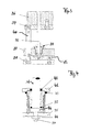
- In vereinfachter, schematisierter Darstellung eine etwas abgewandelte Ausführungsform des Auswerfersystems .
- Fig. 4
- Im größeren Maßstab den in Fig. 3
umkreisten Bereich 39.
- Fig. 1
- in a perspective simplified illustration of the ejector system as a whole;
- Fig. 2
- a section through the essential part of the invention for the ejector system.
- Fig. 3
- In a simplified, schematic representation of a slightly modified embodiment of the ejector system.
- Fig. 4
- On a larger scale, the
area 39 circled in FIG. 3.
Das Auswerfersystem weist in Fig. 1 einen in sich starren Rahmen 15 auf. Dieser besteht im gezeigten Ausführungsbeispiel aus einer oberen und einer unteren Tragplatte 17 und 18, die durch vier Säulen 20 starr mit einander verbunden sind. Auf der oberen Tragplatte ist ein Werkzeugunterteil 16, z.B. aus einem Kunststoff, befestigt, dessen Oberseite der nicht dargestellten Form zugewandt ist. An den Säulen 20 ist eine dritte Platte 3 in axialer Richtung beweglich geführt. Diese wird von einem nicht dargestellten Auswerfer-Antrieb nach oben (Pfeil 2) bewegt und von auf den Säulen angeordneten Rückstellfedern 21 in entgegengesetzter Richtung beaufschlagt und - in der Ruhestellung des Systems - mit Vorspannung gegen auf der unteren Tragplatte 18 angeordnete Begrenzungsanschläge 24 gedrückt, von denen zur Vereinfachung nur zwei in der Figur gezeigt sind.The ejector system has in Fig. 1 a
Der Werkzeugunterteil 16 weist einen, z.B. zentralen, Führungskanal für den Schaft des eigentlichen Auswerferteils 1 auf. Dieser ragt durch eine entsprechende Öffnung in der oberen Tragplatte 17 bis zu der dritten, beweglich geführten Platte 3 und bildet mit dieser eine Bewegungseinheit, die in Fig. 2 im Schnitt näher gezeigt ist. Der Auswerferteil 1 weist an seinem unteren Ende einen scheibenförmigen Kopf 1a von größerem Durchmesser als der Schaft auf. Dieser Kopf liegt mit axialem und radialem Freiraum in einer geschlossenen Kammer 22 der Platte 3.The tool
Zu diesem Zweck weist die Platte 3 eine größere mittlere Ausnehmung auf, in die die Gewindekrägen von zwei Schraubkappen 4 und 5 von entgegengesetzten Seiten her eingreifen und mit einander verschraubt sind. Zwischen diesen Kappen wird die Kammer 22 gebildet. Die Kappen 4 und 5 liegen jeweils mit entsprechenden Krägen auf den entgegengesetzten Seiten der dritten Platte 3 an und sind so mit dieser Platte fest verspannbar.For this purpose, the
In der unteren Kappe 5 ist mittig ein mit seiner Stirnseite in die Kammer 22 ragendes Justierelement 8 axial verstellbar angeordnet. Im dargestellten Beispiel ist das Element 8 in einer zentralen Gewindebohrung der unteren Tragplatte 5 schraubbar. Auf der Stirnseite des Justierelementes liegt der Kopfteil 1a mit seiner Unterseite auf. Durch verstellen des Justierelementes 8 lässt sich die axiale Stellung des Auswerferkopfs 1 a in der Kammer 22 verändern. Damit verstellt sich auch die Stirnseite des Auswerferschafts gegenüber der Oberfläche des Werkzeugunterteils 16. Beide Flächen sollten für einen störungsfreien Betrieb bündig liegen. Da aber bei Temperaturschwankungen die aus Metall bestehenden Teile des Auswerfers 1 und der, z.B. aus Kunststoff oder einem anderen Werkstoff bestehende, Werkzeugunterteil 16 sich unterschiedlich ausdehnen, ergibt sich automatisch eine entsprechende gegenseitige Verschiebung der beiden Flächen, was sich schädigend auf das Formteil auswirkt. Mit Hilfe der Justiereinrichtung lässt sich jeder solcher Einfluss auf einfache und zuverlässige Weise vermeiden, indem die relative axiale Lage der beiden Teile entsprechend verändert wird.In the lower cap 5 a centrally projecting with its end face into the
Das Justierelement ist von außerhalb des Systems durch eine Öffnung 19 in der unteren Tragplatte leicht zu erreichen. Die Krägen der Schraubkappen können mit Schraubschlüssel-Flächen versehen sein, die am Teil 4 in Fig. 1 dargestellt.The adjustment element is easily accessible from outside the system through an opening 19 in the lower support plate. The collars of the screw caps can be provided with wrench surfaces, which are shown on
Eine wesentliche Weiterentwicklung besteht in der Einbringung eines Ringteils 7 aus elastisch verformbarem Material in die Kammer zwischen Kammerdecke und Oberseite des Auswerferkopfs 1a. Er sollte eine solche axiale Dicke aufweisen, dass er in jeder Einstellung des Auswerfers unter mehr oder weniger starker Verformung steht, so dass die axiale Lage des Kopfes in der Kammer stets definierbar ist. Außerdem wird damit der Auswerfer zusätzlich gegen eine Drehung relativ zu den anderen Teilen gesichert, was ebenfalls dazu beiträgt, das Formteil vor Beschädigungen zu schützen.A significant further development consists in the introduction of an
Wenn der Gummiring 7 - abweichend von der Darstellung in Fig.2 - in einer bevorzugten Ausführung so bemessen wird, dass er bündig zum Auswerferteil 1 angeordnet ist, lässt sich noch besser eine Verschmutzung der inneren Kammer 22 gewährleisten. Auch werden die Sitze durch die elastische Lagerung geschont, die Maßhaltigkeit bleibt gewährleistet. Die schwimmende Lagerung ermöglicht einen Ausgleich von auftretenden Dehnungen in allen Richtungen senkrecht zur Achse des Auswerferteils 1. Eine Präzisionsplatte ist nicht mehr erforderlich. Das System ist weitgehend verkantungssicher und wartungsfrei. Die Lebensdauer der Teile verlängert sich.Deviating from the illustration in FIG. 2, if the
Das Ausführungsbeispiel nach Fig. 3 und 4 entspricht in den wesentlichen Elementen dem zuvor beschriebenen Ausführungsbeispiel. Auf dem oberen Montageboden 37 ist die Werkzeugform 36 montiert. Mehrere Führungssäulen 40 (nur eine ist dargestellt) verbinden den Montageboden mit der Grundplatte 38. Auf den Führungssäulen 40 ist die Auswerferplatte 33 gegen die Rückstellkraft von nicht gezeigten Federn gleitend geführt und ruht normalerweise, wie gezeigt, auf Begrenzungs-Anschlägen 45.The embodiment of FIGS. 3 and 4 corresponds in the essential elements of the embodiment described above. On the upper mounting
Wie insbesondere aus Fig. 4 ersichtlich, sind in einer Bohrung der Auswerferplatte 33 von oben und von unten mit einander verschraubbare Kappen 41 und 35 eingeführt. Die obere Kappe 41, auch Auswerferhülse benannt, liegt mit ihrem Kragen unter Vorspannen eines zur Verdrehsicherung dienenden Druckringes 43 auf der Oberseite der Auswerferplatte 33 an, während die untere Kappe 35, auch als Überwurfmutter benannt, mit ihrem Kragen von unten an der Auswerferplatte 33 anliegt. Beide Kappen begrenzen eine innere Kammer, in der der Kopf 46 des Auswerferstiftes 31 liegt. Dieser ist oberhalb des Kopfes eng von dem zur Höhenverstellung dienenden Druckring 32 umgeben.As can be seen in particular from FIG. 4, caps 41 and 35 can be screwed in from above and from below in a bore of the
Die zur Höhenverstellung dienende Einstellungsschraube 34, die in der Überwurfmutter 35 schraubbar ist, ragt mit ihrem Kopf leicht zugänglich nach außen und ist durch eine Sicherungsmutter in jeder ihrer Einstellung abgesichert. Dadurch ist der Einstellbereich besonders leicht und mit einfachen Werkzeugen zugänglich. Der Druckring 32 dient zusammen mit einem im Kragen der Auswerferhülse 41 eingebetteten Dichtring 42 zur Abdichtung der Innenkammer und der Bohrung in der Auswerferhülse.Serving for
Wie ersichtlich, entspricht der generelle Aufbau und die Funktionsweise des Ausführungsbeispiels nach Fig. 3 und 4 denen des Beispiels aus Fig. 1 und 2.As can be seen, corresponds to the general structure and operation of the embodiment of FIGS. 3 and 4 those of the example of FIGS. 1 and 2.
Claims (10)
Applications Claiming Priority (1)
| Application Number | Priority Date | Filing Date | Title |
|---|---|---|---|
| DE200510013563 DE102005013563B4 (en) | 2005-03-23 | 2005-03-23 | Ejector system for molding boxes |
Publications (1)
| Publication Number | Publication Date |
|---|---|
| EP1704945A1 true EP1704945A1 (en) | 2006-09-27 |
Family
ID=36013263
Family Applications (1)
| Application Number | Title | Priority Date | Filing Date |
|---|---|---|---|
| EP06100051A Withdrawn EP1704945A1 (en) | 2005-03-23 | 2006-01-03 | Ejectorsystem for moulds |
Country Status (2)
| Country | Link |
|---|---|
| EP (1) | EP1704945A1 (en) |
| DE (1) | DE102005013563B4 (en) |
Cited By (6)
| Publication number | Priority date | Publication date | Assignee | Title |
|---|---|---|---|---|
| CN102198711A (en) * | 2011-04-13 | 2011-09-28 | 青岛海信模具有限公司 | Device for regulating length of angle ejector rod |
| CN103223461A (en) * | 2013-04-11 | 2013-07-31 | 芜湖乐锐思信息咨询有限公司 | Upward ejection core rod with characteristic of easy replacement |
| CN103537632A (en) * | 2013-10-24 | 2014-01-29 | 重庆新红旗缸盖制造有限公司 | Core ejection device for sand core making machine |
| CN103862002A (en) * | 2014-04-02 | 2014-06-18 | 广西玉柴机器股份有限公司 | Lifting and returning device of lower ejecting core plate |
| CN110406025A (en) * | 2019-06-19 | 2019-11-05 | 江苏雨燕模业科技股份有限公司 | A kind of cooling fan of engine molding machine |
| CN112676541A (en) * | 2020-12-27 | 2021-04-20 | 林旺开 | Lost foam precision composite casting equipment |
Families Citing this family (1)
| Publication number | Priority date | Publication date | Assignee | Title |
|---|---|---|---|---|
| CN107457372B (en) * | 2017-09-22 | 2018-12-11 | 芜湖火龙动力科技有限公司 | A kind of sand box locking device |
Citations (3)
| Publication number | Priority date | Publication date | Assignee | Title |
|---|---|---|---|---|
| US3348606A (en) * | 1965-06-15 | 1967-10-24 | Nat Acme Co | Molding machine transfer mechanism |
| DE2418658A1 (en) * | 1974-04-18 | 1975-10-30 | Hanning Elektro Werke | INJECTION MOLD |
| DE10114714C1 (en) * | 2001-03-26 | 2002-10-17 | Winter Fritz Eisengiesserei | Device for the production of inner and outer parts of a mold has an ejector which can be inserted into the opening of the molding tool to eject the molded part formed |
Family Cites Families (3)
| Publication number | Priority date | Publication date | Assignee | Title |
|---|---|---|---|---|
| JP3304041B2 (en) * | 1996-08-09 | 2002-07-22 | 新東工業株式会社 | Pattern plate removal device |
| AT1887U1 (en) * | 1997-01-10 | 1998-01-26 | Engel Gmbh Maschbau | EJECTOR UNIT FOR AN INJECTION MOLDING MACHINE |
| DE202004018293U1 (en) * | 2004-11-25 | 2005-03-17 | Knarr Rainer | Ejector pin for injection and pressure die casting molding tools has opposing flats on the head to prevent rotation in an ejector plate |
-
2005
- 2005-03-23 DE DE200510013563 patent/DE102005013563B4/en not_active Expired - Fee Related
-
2006
- 2006-01-03 EP EP06100051A patent/EP1704945A1/en not_active Withdrawn
Patent Citations (3)
| Publication number | Priority date | Publication date | Assignee | Title |
|---|---|---|---|---|
| US3348606A (en) * | 1965-06-15 | 1967-10-24 | Nat Acme Co | Molding machine transfer mechanism |
| DE2418658A1 (en) * | 1974-04-18 | 1975-10-30 | Hanning Elektro Werke | INJECTION MOLD |
| DE10114714C1 (en) * | 2001-03-26 | 2002-10-17 | Winter Fritz Eisengiesserei | Device for the production of inner and outer parts of a mold has an ejector which can be inserted into the opening of the molding tool to eject the molded part formed |
Cited By (7)
| Publication number | Priority date | Publication date | Assignee | Title |
|---|---|---|---|---|
| CN102198711A (en) * | 2011-04-13 | 2011-09-28 | 青岛海信模具有限公司 | Device for regulating length of angle ejector rod |
| CN102198711B (en) * | 2011-04-13 | 2014-02-26 | 青岛海信模具有限公司 | Device for regulating length of angle ejector rod |
| CN103223461A (en) * | 2013-04-11 | 2013-07-31 | 芜湖乐锐思信息咨询有限公司 | Upward ejection core rod with characteristic of easy replacement |
| CN103537632A (en) * | 2013-10-24 | 2014-01-29 | 重庆新红旗缸盖制造有限公司 | Core ejection device for sand core making machine |
| CN103862002A (en) * | 2014-04-02 | 2014-06-18 | 广西玉柴机器股份有限公司 | Lifting and returning device of lower ejecting core plate |
| CN110406025A (en) * | 2019-06-19 | 2019-11-05 | 江苏雨燕模业科技股份有限公司 | A kind of cooling fan of engine molding machine |
| CN112676541A (en) * | 2020-12-27 | 2021-04-20 | 林旺开 | Lost foam precision composite casting equipment |
Also Published As
| Publication number | Publication date |
|---|---|
| DE102005013563B4 (en) | 2006-11-23 |
| DE102005013563A1 (en) | 2006-10-05 |
Similar Documents
| Publication | Publication Date | Title |
|---|---|---|
| DE102010035790B4 (en) | Storage mechanism for a movable clamping plate | |
| EP1704945A1 (en) | Ejectorsystem for moulds | |
| DE3107865C2 (en) | Molding tool for producing burr-free plastic moldings | |
| DE102011007997B4 (en) | Interchangeable inserts in an injection mold or die-casting mold with positioning device | |
| CH708745A1 (en) | Tensioning device. | |
| EP3265304B1 (en) | Powder press and a feed housing having preferably a plurality of stamps which are movable for a transverse press | |
| EP1268123A1 (en) | Device for the detachable mounting of workpieces on machining devices | |
| WO2005102655A1 (en) | Devised for producing moulded parts and structural unit for one such device | |
| DE2131482A1 (en) | Device for compacting pellets | |
| WO2002032645A1 (en) | Device for automatic and simultaneous compensation of an angle error and an axis misalignment in the closing unit of an injection molding machine | |
| EP1328391B1 (en) | Device for compensating tilting in mould clamping units of injection moulding machines | |
| DE19507009C2 (en) | Device for demoulding injection molded parts | |
| EP3722068A1 (en) | Ejection pin with anti-rotation feature | |
| EP1787784B1 (en) | Mould for manufacturing parts by injection moulding, pressure die casting or a deposition method | |
| DE60302471T2 (en) | ALIGNMENT FOR AN INJECTION MOLDING DEVICE | |
| DE3319463C2 (en) | Lining plate for the molding space on molding machines | |
| DE1924894A1 (en) | Machine warehouse | |
| DE29709578U1 (en) | Arrangement in foundry equipment comprising e.g. a molding machine and a conveyor for "green" sand molds | |
| DE1919748U (en) | DEVICE FOR PELLETING THERMOPLASTIC PLASTICS, ESPECIALLY UNDER WATER. | |
| DE20111198U1 (en) | Caliber plate with an insert for a shaping device | |
| EP2783795B1 (en) | Clamping jaw | |
| DE10123268A1 (en) | Quick clamping device for fixing clamping bolt inside cylinder, has retainerless roller bodies in bolt locking mechanism supported by piston cover | |
| EP4000856B1 (en) | Annular nozzle | |
| DE69210172T2 (en) | Linear bearing arrangement | |
| DE19923217A1 (en) | Deflection prevention method for elements under load |
Legal Events
| Date | Code | Title | Description |
|---|---|---|---|
| PUAI | Public reference made under article 153(3) epc to a published international application that has entered the european phase |
Free format text: ORIGINAL CODE: 0009012 |
|
| AK | Designated contracting states |
Kind code of ref document: A1 Designated state(s): AT BE BG CH CY CZ DE DK EE ES FI FR GB GR HU IE IS IT LI LT LU LV MC NL PL PT RO SE SI SK TR |
|
| AX | Request for extension of the european patent |
Extension state: AL BA HR MK YU |
|
| 17P | Request for examination filed |
Effective date: 20070322 |
|
| AKX | Designation fees paid |
Designated state(s): AT BE BG CH CY CZ DE DK EE ES FI FR GB GR HU IE IS IT LI LT LU LV MC NL PL PT RO SE SI SK TR |
|
| GRAP | Despatch of communication of intention to grant a patent |
Free format text: ORIGINAL CODE: EPIDOSNIGR1 |
|
| STAA | Information on the status of an ep patent application or granted ep patent |
Free format text: STATUS: THE APPLICATION IS DEEMED TO BE WITHDRAWN |
|
| 18D | Application deemed to be withdrawn |
Effective date: 20100720 |