EP1704793A2 - Behälter für flüssige kosmetische Produkte - Google Patents
Behälter für flüssige kosmetische Produkte Download PDFInfo
- Publication number
- EP1704793A2 EP1704793A2 EP06005562A EP06005562A EP1704793A2 EP 1704793 A2 EP1704793 A2 EP 1704793A2 EP 06005562 A EP06005562 A EP 06005562A EP 06005562 A EP06005562 A EP 06005562A EP 1704793 A2 EP1704793 A2 EP 1704793A2
- Authority
- EP
- European Patent Office
- Prior art keywords
- tube
- shaped container
- discharger
- liquid cosmetic
- return valve
- Prior art date
- Legal status (The legal status is an assumption and is not a legal conclusion. Google has not performed a legal analysis and makes no representation as to the accuracy of the status listed.)
- Withdrawn
Links
- 239000007788 liquid Substances 0.000 title claims abstract description 43
- 239000002537 cosmetic Substances 0.000 title claims abstract description 41
- 238000007789 sealing Methods 0.000 claims description 6
- 230000000149 penetrating effect Effects 0.000 claims 1
- 230000008602 contraction Effects 0.000 abstract description 2
- 238000010521 absorption reaction Methods 0.000 description 1
Images



Classifications
-
- A—HUMAN NECESSITIES
- A46—BRUSHWARE
- A46B—BRUSHES
- A46B11/00—Brushes with reservoir or other means for applying substances, e.g. paints, pastes, water
- A46B11/001—Brushes with reservoir or other means for applying substances, e.g. paints, pastes, water with integral reservoirs
- A46B11/002—Brushes with reservoir or other means for applying substances, e.g. paints, pastes, water with integral reservoirs pressurised at moment of use manually or by powered means
- A46B11/0041—Flexible or deformable reservoirs, e.g. resilient bulbs, compressible tubes
-
- A—HUMAN NECESSITIES
- A45—HAND OR TRAVELLING ARTICLES
- A45D—HAIRDRESSING OR SHAVING EQUIPMENT; EQUIPMENT FOR COSMETICS OR COSMETIC TREATMENTS, e.g. FOR MANICURING OR PEDICURING
- A45D34/00—Containers or accessories specially adapted for handling liquid toiletry or cosmetic substances, e.g. perfumes
- A45D34/04—Appliances specially adapted for applying liquid, e.g. using roller or ball
- A45D34/042—Appliances specially adapted for applying liquid, e.g. using roller or ball using a brush or the like
-
- B—PERFORMING OPERATIONS; TRANSPORTING
- B65—CONVEYING; PACKING; STORING; HANDLING THIN OR FILAMENTARY MATERIAL
- B65D—CONTAINERS FOR STORAGE OR TRANSPORT OF ARTICLES OR MATERIALS, e.g. BAGS, BARRELS, BOTTLES, BOXES, CANS, CARTONS, CRATES, DRUMS, JARS, TANKS, HOPPERS, FORWARDING CONTAINERS; ACCESSORIES, CLOSURES, OR FITTINGS THEREFOR; PACKAGING ELEMENTS; PACKAGES
- B65D85/00—Containers, packaging elements or packages, specially adapted for particular articles or materials
- B65D85/07—Containers, packaging elements or packages, specially adapted for particular articles or materials for compressible or flexible articles
- B65D85/08—Containers, packaging elements or packages, specially adapted for particular articles or materials for compressible or flexible articles rod-shaped or tubular
- B65D85/14—Containers, packaging elements or packages, specially adapted for particular articles or materials for compressible or flexible articles rod-shaped or tubular for collapsible empty tubes
-
- A—HUMAN NECESSITIES
- A45—HAND OR TRAVELLING ARTICLES
- A45D—HAIRDRESSING OR SHAVING EQUIPMENT; EQUIPMENT FOR COSMETICS OR COSMETIC TREATMENTS, e.g. FOR MANICURING OR PEDICURING
- A45D34/00—Containers or accessories specially adapted for handling liquid toiletry or cosmetic substances, e.g. perfumes
- A45D2034/002—Accessories
-
- A—HUMAN NECESSITIES
- A45—HAND OR TRAVELLING ARTICLES
- A45D—HAIRDRESSING OR SHAVING EQUIPMENT; EQUIPMENT FOR COSMETICS OR COSMETIC TREATMENTS, e.g. FOR MANICURING OR PEDICURING
- A45D2200/00—Details not otherwise provided for in A45D
- A45D2200/05—Details of containers
- A45D2200/054—Means for supplying liquid to the outlet of the container
-
- A—HUMAN NECESSITIES
- A45—HAND OR TRAVELLING ARTICLES
- A45D—HAIRDRESSING OR SHAVING EQUIPMENT; EQUIPMENT FOR COSMETICS OR COSMETIC TREATMENTS, e.g. FOR MANICURING OR PEDICURING
- A45D34/00—Containers or accessories specially adapted for handling liquid toiletry or cosmetic substances, e.g. perfumes
- A45D34/04—Appliances specially adapted for applying liquid, e.g. using roller or ball
- A45D34/042—Appliances specially adapted for applying liquid, e.g. using roller or ball using a brush or the like
- A45D34/043—Appliances specially adapted for applying liquid, e.g. using roller or ball using a brush or the like movable within the container
-
- A—HUMAN NECESSITIES
- A46—BRUSHWARE
- A46B—BRUSHES
- A46B2200/00—Brushes characterized by their functions, uses or applications
- A46B2200/10—For human or animal care
- A46B2200/1046—Brush used for applying cosmetics
Definitions
- the present invention relates to a liquid cosmetic case in which the upper side of a tube-shaped container includes a brush, liquid cosmetic is discharged, a sealing-structured discharger is coupled, and at the same time, a cap is coupled in a way that a non-return valve is formed at one side of the upper part of the tube-shaped container.
- a liquid cosmetic container forms an opening at the upper part of the tube-shaped container, and simply fixes a brush. And a user can make up through the direct discharge to the brush of the liquid cosmetic saved in the tube-shaped container by pressing and releasing the tube-shaped container. But in this kind of liquid cosmetic container, the tube-shaped container is often pressed carelessly, and the liquid cosmetic is leaked, so that it is not easy to carry or to safely keep them.
- the inside of the opening formed at the upper part of the tube-shaped container saving liquid includes a brush, and a discharger formed by a liquid guiding passage and a discharge hole is coupled, so that when the tube-shaped container is pressed, the discharger goes up, then liquid cosmetic is discharged to the brush side through the liquid guiding passage and the discharge hole, making it possible for a user to make up, and when the container is released, the discharger goes down, then the air flows into the inside of the tube-shaped container, and the pressed container is restored. And as the press and the release are repeated, the discharger goes up and down, and the opening is opened and closed, so that only a necessary amount of liquid cosmetic contained in the tube-shaped container is discharged for use.
- this liquid cosmetic container is inconvenient in that as the discharge of liquid cosmetic through the liquid guiding passage and the discharge hole formed at the discharger is repeated, the liquid cosmetic can be stuck on the liquid guiding passage or the discharge hole or even can block the passage, then the contracted tube-shaped container cannot be restored to the original state, and the press and the release cannot be done easily so that a user cannot easily make up.
- a discharger with a brush is coupled on the opening formed at the central upper part of a tube-shaped container, and a non-return valve is formed at one upper side of the tube-shaped container along with the coupled cap, so that when pressed, only a necessary amount of liquid cosmetic is discharged through the discharger for easy use and at the same time, when the power at the tube-shaped container is released by the non-return valve formed at one side of the tube-shaped container, the tube-shaped container is easily restored, so that the press on the tube-shaped container can be easily repeated, and the liquid cosmetic is easily discharged for the convenient use.
- FIG. 1 is a perspective view of a cosmetic case according to the present invention
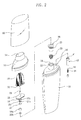
- FIG. 2 is an exploded perspective view of the cosmetic case according to the present invention.
- FIG. 3 is a sectional view by A-A line of the cosmetic case according to the present invention.
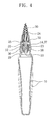
- FIG. 4 is a sectional view by B-B line in the state a tube-shaped container is pressed according to the present invention
- FIG. 5 is a sectional view of a non-return valve in the state a tube-shaped valve is pressed according to the present invention
- FIG. 6 is a sectional view of a non-return valve in the state the pressure on a tube-shaped valve is released according to the present invention.
- FIG. 1 is a perspective view of a cosmetic case according to the present invention
- FIG. 2 is an exploded perspective view of the cosmetic case according to the present invention
- FIG. 3 is a sectional view by A-A line of the cosmetic case according to the present invention
- FIG. 4 is a sectional view by B-B line in the state a tube-shaped container is pressed according to the present invention
- FIG. 5 is a sectional view of a non-return valve in the state a tube-shaped valve is pressed according to the present invention
- FIG. 6 is a sectional view of a non-return valve in the state the pressure on a tube-shaped valve is released according to the present invention.
- an opening 12 formed at the central upper part of a tube-shaped container 10 is coupled with a discharger 20 with a brush 30, and at the same time, a non-return valve 40 is formed at one side of the upper part of the tube-shaped container 10 along with a supporting cap 50 and a cap 60, so that liquid cosmetic is discharged through the discharger 20 for easy use, and at the same time, the tube-shaped container 10 are easily pressed and released by the non-return valve 40 formed at one side of the tube-shaped container 10.
- an opening 12 along with an inner locking wheel 14 are formed in the upper side of a tube-shaped container 10, and a discharger 20 coupled with a brush 30 and a fixing support 36 is formed inside the opening 12.
- a divided opening 22 is formed at the lower side of the discharger 20, and by horizontally putting a liquid guiding passage 23 at the central side, the liquid guiding passage 23 is connected with a discharge hole 24 penetrated to the upper side of the central part. And a fixing plate 25 is formed along with a step wheel 26.
- upper and lower grooves 27a 27b are formed from the upper part of the circumference part of the discharger 20, and the upper and the lower sealing O-rings 28a 28b are interposed.
- a brush plate 32 with the brush 30 is closely coupled at the upper side of the fixing plate 25 where the step wheel is formed.
- an outer protrusion wheel 37 is formed at the lower side of the discharger 20
- an inner ring-shaped step 38 passes through the inner side of the fixing support 36, and a spring 29 is inserted at the lower side of the protruded discharger 20 for fixing.
- the discharger 20 including the brush 30 and the fixing support 36 at the lower side to the inside of the opening 12 where the tube-shaped container 10 is formed at the upper side, the discharger 20 is safely connected, and the outer protrusion wheel 37 formed at the outer circumference part of the fixing part 36 coupled at the lower circumference part of the discharger 20 does not break away by not being caught at the inner locking wheel formed at the upper side of the inner circumference wall of the opening 12.
- a hole 16 is formed at one side of the upper side of the tube-shaped container 10, and a non-return valve is connected, opening and closing the valve hole 41 by a ball 42 and a spring 44.
- the supporting cap 50 is formed at the upper side of the tube-shaped container 10 where the discharger 20, the brush 30 and the non-return valve 40 are coupled, and the brush 30 penetrates the central part at the upper side of the discharger 20 coupled at the opening 12 of the tube-shaped container 10, forming a central hole 52.
- the cap 60 is coupled at the upper side of the supporting cap 50.
- the discharger 20 goes up by the pressure of the liquid cosmetic contained in the tube-shaped container 10, then the inner ring-shaped step 38 is opened, then the inner side of tube-shaped container 10 is connected with the divided opening 22, the liquid guiding passage 23 and the discharge hole 24 forming the discharger, then the liquid cosmetic contained in the tube-shaped container 10 is discharged to the discharge hole 24 and then to the brush 30.
- the discharger 20 including the brush 30 goes down by the spring 29, and as described in FIG. 3, the lower sealing O-ring 28b seals the inner ring-shaped step 38, then the divided opening 22, the liquid guiding passage 23 and the discharge hole 24 of the discharger 20 are closed.
- the upper sealing O-ring 28a interposed at the upper groove 27a of the circumference part of the discharger 20 blocks the leakage of liquid cosmetic through the fixing support 36 when the liquid cosmetic discharged to the liquid guiding passage 23 and the discharge hole 24 through the divided opening 22 as the inner ring-shaped step 38 is opened as the discharger goes up by the pressure of the tube-shaped container 10.
- the upper and lower sealing O-rings 28a 28b interposed at the upper and the lower grooves 27a 27b at the circumference part of the discharger 20 should be safely carried and kept, avoiding the leakage of the liquid cosmetic contained in the tube-shaped container 10 by sealing the inner part of the fixing support 36.
- the hole 16 is formed at one side of the upper part of the tube-shaped container 10, and the non-return valve 40 opening and closing the valve hole 41 by the ball and the spring 42 is coupled.
- the ball goes up, then the valve hole 41 is closed, and when the press on the tube-shaped container 10 is released, as described in FIG. 6, the ball 42 goes down by the absorption force absorbed by the expansive force of the tube-shaped container 10, then the valve hole 41 formed at the non-return valve 40 is opened, then the air flows into the tube-shaped container, making the restoration of the tube-shaped container 10 easy.
- the discharger including the brush is coupled at the opening formed at the central upper part of the tube-shaped container, and at the same time, the non-return valve is formed at one side of the upper part of the tube-shaped container along with the cap, so that when the tube-shaped container is pressed, only a necessary amount of liquid cosmetic is discharged through the discharger, and when the press on the tube-shaped container is released, as the valve hole formed at the non-return valve is opened and closed, the air flows in and is blocked, which makes the restoration of the tube-shaped container easy, so that the discharge and the use of the liquid cosmetic by the repeated presses become easy.
Landscapes
- Engineering & Computer Science (AREA)
- Mechanical Engineering (AREA)
- Containers And Packaging Bodies Having A Special Means To Remove Contents (AREA)
- Closures For Containers (AREA)
- Brushes (AREA)
Applications Claiming Priority (1)
| Application Number | Priority Date | Filing Date | Title |
|---|---|---|---|
| KR1020050023576A KR100626174B1 (ko) | 2005-03-22 | 2005-03-22 | 액상 화장품용기 |
Publications (2)
| Publication Number | Publication Date |
|---|---|
| EP1704793A2 true EP1704793A2 (de) | 2006-09-27 |
| EP1704793A3 EP1704793A3 (de) | 2009-05-20 |
Family
ID=36524440
Family Applications (1)
| Application Number | Title | Priority Date | Filing Date |
|---|---|---|---|
| EP06005562A Withdrawn EP1704793A3 (de) | 2005-03-22 | 2006-03-17 | Behälter für flüssige kosmetische Produkte |
Country Status (4)
| Country | Link |
|---|---|
| US (1) | US7329064B2 (de) |
| EP (1) | EP1704793A3 (de) |
| JP (1) | JP2006263464A (de) |
| KR (1) | KR100626174B1 (de) |
Cited By (2)
| Publication number | Priority date | Publication date | Assignee | Title |
|---|---|---|---|---|
| WO2011035096A3 (en) * | 2009-09-18 | 2012-01-05 | The Procter & Gamble Company | Unit dose dispensing apparatus |
| CN109937068A (zh) * | 2016-10-28 | 2019-06-25 | 尼普洛株式会社 | 涂敷器以及药液涂敷器 |
Families Citing this family (17)
| Publication number | Priority date | Publication date | Assignee | Title |
|---|---|---|---|---|
| KR100789290B1 (ko) | 2006-09-28 | 2007-12-28 | 변영광 | 튜브형 액상 화장품용기 |
| EP2259696B1 (de) * | 2008-03-31 | 2018-03-28 | The Procter and Gamble Company | Verpackung zur ausgabe eines körperpflegeprodukts |
| KR100857177B1 (ko) | 2008-05-23 | 2008-09-08 | (주)에스엔피월드 | 액상 화장용기 |
| KR200455563Y1 (ko) | 2009-11-24 | 2011-09-15 | (주)아모레퍼시픽 | 향의 손실을 방지하는 용기 |
| KR101180737B1 (ko) * | 2010-10-04 | 2012-09-07 | (주)연우 | 회전개폐형 브러쉬 튜브용기 |
| KR20140140853A (ko) | 2013-05-30 | 2014-12-10 | 황재광 | 화장용 튜브용기 |
| USD753402S1 (en) * | 2014-07-29 | 2016-04-12 | Anisa International Inc. | Cosmetic applicator |
| USD758739S1 (en) * | 2014-07-29 | 2016-06-14 | Anisa International Inc. | Cosmetic applicator |
| USD758738S1 (en) * | 2014-07-29 | 2016-06-14 | Anisa International Inc. | Cosmetic applicator |
| KR101886142B1 (ko) * | 2014-08-08 | 2018-08-08 | (주)아모레퍼시픽 | 탄성을 갖는 실리콘 재질의 도포구가 구비된 화장품 튜브용기 |
| WO2016080313A1 (ja) * | 2014-11-19 | 2016-05-26 | キョーラク株式会社 | 積層剥離容器 |
| JP6761159B2 (ja) | 2014-11-19 | 2020-09-23 | キョーラク株式会社 | 積層剥離容器 |
| KR101801485B1 (ko) * | 2016-10-11 | 2017-11-27 | 조지원 | 내용물 토출형 화장품 용기 |
| KR102019348B1 (ko) * | 2017-11-28 | 2019-09-09 | 주식회사 월드스폰지 | 핸들링부가 구비된 화장품 용기 |
| WO2020093282A1 (en) * | 2018-11-07 | 2020-05-14 | L'oreal | Device for packaging and dispensing a product having inclined elastically deformable teeth |
| JP7257911B2 (ja) * | 2019-07-31 | 2023-04-14 | 株式会社吉野工業所 | 塗布容器 |
| KR102777798B1 (ko) * | 2020-09-08 | 2025-03-06 | 현대자동차주식회사 | 자동차용 리저버 탱크의 공기역류 방지 장치 |
Family Cites Families (8)
| Publication number | Priority date | Publication date | Assignee | Title |
|---|---|---|---|---|
| JPS594567Y2 (ja) | 1978-05-22 | 1984-02-10 | 泉精密工業株式会社 | 整髪剤等の噴霧器 |
| JPH0722951U (ja) * | 1993-09-29 | 1995-04-25 | 花王株式会社 | 注出容器 |
| US5678941A (en) * | 1994-08-01 | 1997-10-21 | Mitsubishi Pencil Co., Ltd. | Liquid applicator |
| JPH10397A (ja) | 1996-04-20 | 1998-01-06 | Kao Corp | 泡吐出容器 |
| US6412997B2 (en) * | 1999-11-15 | 2002-07-02 | Joseph J. Berke | Pump and liquid applicator apparatus for health and beauty products |
| US6586483B2 (en) * | 2001-01-08 | 2003-07-01 | 3M Innovative Properties Company | Foam including surface-modified nanoparticles |
| JP4681159B2 (ja) | 2001-07-10 | 2011-05-11 | ホーユー株式会社 | 毛髪化粧料用塗布具 |
| US7044137B2 (en) * | 2002-08-23 | 2006-05-16 | Appliances Development Corporation | Hair treating device |
-
2005
- 2005-03-22 KR KR1020050023576A patent/KR100626174B1/ko not_active Expired - Fee Related
-
2006
- 2006-03-13 JP JP2006067042A patent/JP2006263464A/ja active Pending
- 2006-03-17 EP EP06005562A patent/EP1704793A3/de not_active Withdrawn
- 2006-03-21 US US11/384,397 patent/US7329064B2/en not_active Expired - Fee Related
Cited By (4)
| Publication number | Priority date | Publication date | Assignee | Title |
|---|---|---|---|---|
| WO2011035096A3 (en) * | 2009-09-18 | 2012-01-05 | The Procter & Gamble Company | Unit dose dispensing apparatus |
| CN102725615A (zh) * | 2009-09-18 | 2012-10-10 | 宝洁公司 | 单位剂量分配设备 |
| CN109937068A (zh) * | 2016-10-28 | 2019-06-25 | 尼普洛株式会社 | 涂敷器以及药液涂敷器 |
| EP3524313A4 (de) * | 2016-10-28 | 2020-07-22 | Nipro Corporation | Beschichtungswerkzeug und flüssiges arzneimittelbeschichtungswerkzeug |
Also Published As
| Publication number | Publication date |
|---|---|
| US7329064B2 (en) | 2008-02-12 |
| KR100626174B1 (ko) | 2006-09-20 |
| US20060216105A1 (en) | 2006-09-28 |
| JP2006263464A (ja) | 2006-10-05 |
| EP1704793A3 (de) | 2009-05-20 |
Similar Documents
| Publication | Publication Date | Title |
|---|---|---|
| EP1704793A2 (de) | Behälter für flüssige kosmetische Produkte | |
| EP3682973B1 (de) | Pumpenanordnung und behälter mit inhaltsentladefunktion | |
| KR100777364B1 (ko) | 공기 펌프식 배출장치 및 이를 포함하는 생활용품용 용기 | |
| US6644489B2 (en) | Container assembly having a cover cap provided with a pump member to pump out air from a container | |
| US20080089173A1 (en) | Securing device for a mixer to allow dynamic communication between a mixer housing and a mixer inlet portion of the mixer | |
| KR101636820B1 (ko) | 튜브용기의 내용물 유출 방지용 밸브 | |
| KR101760627B1 (ko) | 립글로스 용기 | |
| KR20160054975A (ko) | 압축기체 공급장치 | |
| KR200294064Y1 (ko) | 혼합식 화장품 용기 | |
| US7175360B2 (en) | Tube style cosmetic container structure | |
| KR960031292A (ko) | 탄산수 병뚜껑 | |
| AU1762002A (en) | Squeeze liquid dispenser | |
| US7874810B2 (en) | Constant pressure pressurizing water pump | |
| KR100698407B1 (ko) | 화장용 파우더 용기 | |
| KR101817163B1 (ko) | 화장품 용기의 배출 장치 | |
| KR200385928Y1 (ko) | 화장용 파우더 용기 | |
| KR102137999B1 (ko) | 리필 구조를 가지는 휴대용 용기 | |
| CN212040377U (zh) | 一种二元材料混合装置 | |
| US7031635B2 (en) | Toner cartridge | |
| DE59914583D1 (de) | Zapfhahn | |
| JP6535127B2 (ja) | スクイズ容器 | |
| US20050027217A1 (en) | Massaging device structure | |
| US7121302B2 (en) | Air tap assembly | |
| CN223310986U (zh) | 一种提手弹盖杯 | |
| KR102134989B1 (ko) | 일체형 체크밸브 |
Legal Events
| Date | Code | Title | Description |
|---|---|---|---|
| PUAI | Public reference made under article 153(3) epc to a published international application that has entered the european phase |
Free format text: ORIGINAL CODE: 0009012 |
|
| AK | Designated contracting states |
Kind code of ref document: A2 Designated state(s): AT BE BG CH CY CZ DE DK EE ES FI FR GB GR HU IE IS IT LI LT LU LV MC NL PL PT RO SE SI SK TR |
|
| AX | Request for extension of the european patent |
Extension state: AL BA HR MK YU |
|
| PUAL | Search report despatched |
Free format text: ORIGINAL CODE: 0009013 |
|
| AK | Designated contracting states |
Kind code of ref document: A3 Designated state(s): AT BE BG CH CY CZ DE DK EE ES FI FR GB GR HU IE IS IT LI LT LU LV MC NL PL PT RO SE SI SK TR |
|
| AX | Request for extension of the european patent |
Extension state: AL BA HR MK YU |
|
| RIC1 | Information provided on ipc code assigned before grant |
Ipc: A46B 11/00 20060101ALI20090416BHEP Ipc: A45D 34/04 20060101AFI20060721BHEP |
|
| AKX | Designation fees paid | ||
| STAA | Information on the status of an ep patent application or granted ep patent |
Free format text: STATUS: THE APPLICATION IS DEEMED TO BE WITHDRAWN |
|
| 18D | Application deemed to be withdrawn |
Effective date: 20091121 |
|
| REG | Reference to a national code |
Ref country code: DE Ref legal event code: 8566 |