EP1704091B1 - Cooling system for cooling heat-generating installations and for maintaining the temperature of closed-off areas at below cabin temperature in an aircraft - Google Patents
Cooling system for cooling heat-generating installations and for maintaining the temperature of closed-off areas at below cabin temperature in an aircraft Download PDFInfo
- Publication number
- EP1704091B1 EP1704091B1 EP04804435A EP04804435A EP1704091B1 EP 1704091 B1 EP1704091 B1 EP 1704091B1 EP 04804435 A EP04804435 A EP 04804435A EP 04804435 A EP04804435 A EP 04804435A EP 1704091 B1 EP1704091 B1 EP 1704091B1
- Authority
- EP
- European Patent Office
- Prior art keywords
- refrigeration
- cooling system
- refrigerating
- refrigerating agent
- temperature
- Prior art date
- Legal status (The legal status is an assumption and is not a legal conclusion. Google has not performed a legal analysis and makes no representation as to the accuracy of the status listed.)
- Expired - Fee Related
Links
Images
Classifications
-
- B—PERFORMING OPERATIONS; TRANSPORTING
- B64—AIRCRAFT; AVIATION; COSMONAUTICS
- B64D—EQUIPMENT FOR FITTING IN OR TO AIRCRAFT; FLIGHT SUITS; PARACHUTES; ARRANGEMENTS OR MOUNTING OF POWER PLANTS OR PROPULSION TRANSMISSIONS IN AIRCRAFT
- B64D13/00—Arrangements or adaptations of air-treatment apparatus for aircraft crew or passengers, or freight space, or structural parts of the aircraft
- B64D13/06—Arrangements or adaptations of air-treatment apparatus for aircraft crew or passengers, or freight space, or structural parts of the aircraft the air being conditioned
-
- B—PERFORMING OPERATIONS; TRANSPORTING
- B64—AIRCRAFT; AVIATION; COSMONAUTICS
- B64D—EQUIPMENT FOR FITTING IN OR TO AIRCRAFT; FLIGHT SUITS; PARACHUTES; ARRANGEMENTS OR MOUNTING OF POWER PLANTS OR PROPULSION TRANSMISSIONS IN AIRCRAFT
- B64D11/00—Passenger or crew accommodation; Flight-deck installations not otherwise provided for
- B64D11/04—Galleys
-
- F—MECHANICAL ENGINEERING; LIGHTING; HEATING; WEAPONS; BLASTING
- F25—REFRIGERATION OR COOLING; COMBINED HEATING AND REFRIGERATION SYSTEMS; HEAT PUMP SYSTEMS; MANUFACTURE OR STORAGE OF ICE; LIQUEFACTION SOLIDIFICATION OF GASES
- F25D—REFRIGERATORS; COLD ROOMS; ICE-BOXES; COOLING OR FREEZING APPARATUS NOT OTHERWISE PROVIDED FOR
- F25D17/00—Arrangements for circulating cooling fluids; Arrangements for circulating gas, e.g. air, within refrigerated spaces
- F25D17/02—Arrangements for circulating cooling fluids; Arrangements for circulating gas, e.g. air, within refrigerated spaces for circulating liquids, e.g. brine
-
- B—PERFORMING OPERATIONS; TRANSPORTING
- B64—AIRCRAFT; AVIATION; COSMONAUTICS
- B64D—EQUIPMENT FOR FITTING IN OR TO AIRCRAFT; FLIGHT SUITS; PARACHUTES; ARRANGEMENTS OR MOUNTING OF POWER PLANTS OR PROPULSION TRANSMISSIONS IN AIRCRAFT
- B64D13/00—Arrangements or adaptations of air-treatment apparatus for aircraft crew or passengers, or freight space, or structural parts of the aircraft
- B64D13/06—Arrangements or adaptations of air-treatment apparatus for aircraft crew or passengers, or freight space, or structural parts of the aircraft the air being conditioned
- B64D2013/0603—Environmental Control Systems
- B64D2013/0629—Environmental Control Systems with subsystems for cooling food, catering or special loads
-
- B—PERFORMING OPERATIONS; TRANSPORTING
- B64—AIRCRAFT; AVIATION; COSMONAUTICS
- B64D—EQUIPMENT FOR FITTING IN OR TO AIRCRAFT; FLIGHT SUITS; PARACHUTES; ARRANGEMENTS OR MOUNTING OF POWER PLANTS OR PROPULSION TRANSMISSIONS IN AIRCRAFT
- B64D13/00—Arrangements or adaptations of air-treatment apparatus for aircraft crew or passengers, or freight space, or structural parts of the aircraft
- B64D13/06—Arrangements or adaptations of air-treatment apparatus for aircraft crew or passengers, or freight space, or structural parts of the aircraft the air being conditioned
- B64D2013/0603—Environmental Control Systems
- B64D2013/0674—Environmental Control Systems comprising liquid subsystems
-
- F—MECHANICAL ENGINEERING; LIGHTING; HEATING; WEAPONS; BLASTING
- F25—REFRIGERATION OR COOLING; COMBINED HEATING AND REFRIGERATION SYSTEMS; HEAT PUMP SYSTEMS; MANUFACTURE OR STORAGE OF ICE; LIQUEFACTION SOLIDIFICATION OF GASES
- F25B—REFRIGERATION MACHINES, PLANTS OR SYSTEMS; COMBINED HEATING AND REFRIGERATION SYSTEMS; HEAT PUMP SYSTEMS
- F25B2400/00—General features or devices for refrigeration machines, plants or systems, combined heating and refrigeration systems or heat-pump systems, i.e. not limited to a particular subgroup of F25B
- F25B2400/06—Several compression cycles arranged in parallel
-
- Y—GENERAL TAGGING OF NEW TECHNOLOGICAL DEVELOPMENTS; GENERAL TAGGING OF CROSS-SECTIONAL TECHNOLOGIES SPANNING OVER SEVERAL SECTIONS OF THE IPC; TECHNICAL SUBJECTS COVERED BY FORMER USPC CROSS-REFERENCE ART COLLECTIONS [XRACs] AND DIGESTS
- Y02—TECHNOLOGIES OR APPLICATIONS FOR MITIGATION OR ADAPTATION AGAINST CLIMATE CHANGE
- Y02T—CLIMATE CHANGE MITIGATION TECHNOLOGIES RELATED TO TRANSPORTATION
- Y02T50/00—Aeronautics or air transport
- Y02T50/50—On board measures aiming to increase energy efficiency
Definitions
- the present invention relates to a cooling system for cooling heat-generating installations and for maintaining the temperature of closed-off areas at below cabin temperature in an aircraft according to the preamble part of claim 1.
- a cooling system for cooling food in an aircraft is known from patent specification DE 43 40 317 C2 .
- a central refrigerating installation is provided in an aircraft, which conveys refrigerating agent to individual heat exchanger units via a pipe system.
- the heat exchanger units are coupled via additional pipes to transport containers to be cooled in the region of storage places of an onboard kitchen.
- the transport containers contain the food to be cooled in each case.
- This cooling system requires the laying of various pipe systems and is therefore relatively expensive to construct.
- US 2003/0042361 A1 describes a cooling system according to the preamble part of claim 1.
- This cooling system comprises a plurality of refrigeration machines, which are connected to each other by means of a refrigerating agent circulating in a refrigerating transport system with a plurality of refrigeration consumers.
- this prior art document discloses a control unit, which is adapted to control the components of the system. The control unit controls the functioning of each of the components, wherein concrete hints on the way of controlling the components are not included in this prior art.
- One object of the present invention is to provide a cooling system of the kind initially designated, which, with a simple construction, has a large amount of reliability and flexibility in respect of the installation and good matching to the current refrigeration requirement.
- the refrigeration capacity of the cooling system can therefore be set depending on the current requirements by specific activation of the refrigerating installation.
- the efficiency of the cooling system can be increased, as the cooling system can also be operated at low capacity in particular if only a low refrigeration capacity is required, whereas, if a high refrigeration capacity is needed the cooling system can be operated at a correspondingly high capacity. This ultimately results in optimised consumption of electrical energy for operating the refrigerating installation, as well as reduced fuel consumption of the aircraft and increased life of the refrigerating installation.
- the refrigeration capacity is controlled to match the current refrigeration requirement in the aircraft by switching on and off individual refrigeration machines of the refrigerating installation.
- a small refrigeration capacity is required only one refrigeration machine is operated, for example, and when there is a temporarily required increase in the refrigeration capacity at least one further refrigeration machine is additionally activated.
- the invention further provides that the central control unit activates the refrigeration machines in such a way that on average in terms of time they have substantially the same length of operation.
- the invention further provides that the refrigerating installation has at least two refrigeration machines which operate independently of one another and are coupled to the refrigeration transport system in parallel.
- the maximum refrigeration capacity of the refrigerating installation is increased and on the other hand greater reliability of the cooling system is achieved, since the cooling system is still capable of providing a minimum refrigeration capacity by the at least one further refrigeration machine even if one of the refrigeration machines fails.
- the number of refrigeration machines of the refrigerating installation is preferably chosen in such a way that the refrigeration requirement of the aircraft is covered during operation on the ground, in which there is a considerably higher outside temperature round the aircraft than during flight operation at great heights.
- the at least one refrigeration machine generates refrigeration by a cold vapour process.
- a cold vapour process provides the possibility of generating cold at moderately low temperatures with relatively low technical outlay.
- the refrigeration transport system has at least one refrigerating agent pump for circulating the refrigerating agent.
- the refrigeration transport system has at least one store for intermediate storage of refrigerating agent.
- this store thermally caused changes in volume of the refrigerating agent and leakages in the refrigeration transport system can be compensated to a certain extent.
- the at least one refrigeration consumer has a secondary refrigeration transport system in which cold is transmitted from the refrigerating agent by means of a secondary refrigerating agent, preferably air.
- a secondary refrigerating agent preferably air.
- This principle for achieving the object is applied, for example, in an onboard kitchen of the aircraft.
- a kitchen air cooler is used to transmit the cold from the refrigerating agent to the air used as secondary refrigerating agent and to cool food and drinks, for example, with this cooled air.
- the invention further provides that a central control unit is provided which controls the refrigeration capacity depending on at least one parameter indicating the current refrigeration requirement.
- the parameters indicating the current refrigeration requirement reproduce the temperature of the refrigerating agent at at least one point in the refrigeration transport system, preferably at least the outflow temperature of the refrigerating agent from the refrigerating agent pump, or/and information on the refrigeration requirement of the at least one refrigeration consumer or/and the pressure of the refrigerating agent in the refrigeration transport system.
- control is mentioned in connection with this description of the invention, this is intended on the one hand to include the case where individual components of the cooling system are controlled according to preset characteristic curves without feedback. On the other hand this expression is also intended to include the case where components are activated as fed back, i.e. in the sense of automatic control.
- a decentralised mode of procedure is also possible.
- the status of all the refrigeration machines present in the aircraft can be extracted via a databus.
- the refrigeration generators can be automatically activated.
- Prioritisation of this kind can be time-dependent, for example.
- the individual refrigeration machines also to alternate in their order of activation. For example, a refrigeration machine which was activated relatively late in a preceding cooling cycle in comparison to other refrigeration machines, may be switched on earlier, for example as the very first, in a subsequent cooling cycle. This measure also allows the load to be distributed on average in terms of time equally over the individual refrigeration machines.
- the refrigerating agent flows through both a switched off refrigeration machine and a switched on refrigeration machine. In this way the mixed temperature of the refrigerating agent is raised in the flow pipes. It is, however, equally possible for a shut-off valve to be assigned to each refrigeration machine. This can prevent the refrigerating agent flowing through a switched off refrigeration machine and the mixed temperature of the refrigerating agent being raised in the flow pipes.
- control unit detects the outflow temperature of the refrigerating agent leaving the refrigeration machine and activates the refrigeration machine in accordance with the detected outflow temperature.
- the refrigeration capacity of the at least one refrigeration machine can be altered, for example by varying the speed of a compressor used in the refrigeration machine.
- control unit alters the amount of refrigerating agent conveyed in the refrigeration transport system. Depending on the refrigeration capacity required, accordingly more or less refrigerating agent is conveyed from the refrigerating installation to the at least one refrigeration consumer via the refrigeration transport system. This can be done, for example, in that to control the refrigeration capacity the control unit alters the speed of the at least one refrigerating agent pump.
- a cooling system according to the invention is generally designated by 10. It comprises a refrigerating installation 12, a refrigeration transport system 14 and a region 16 in which cold is consumed.
- the refrigerating installation 12 has two refrigeration machines 18 and 20, in which a refrigerating agent is cooled via a cold vapour process generally known in thermodynamics and is conducted into the refrigeration transport system 14 via two parallel pipes 22 and 24. In the refrigeration transport system 14 the two parallel pipes 22 and 24 meet at a point 26. Refrigerating agent is conveyed to a pump unit 30 via an optional conveying pipe 28 provided with a separately activatable shut-off valve 29.
- the pump unit 30 has two pumps 32 and 34, switched parallel to one another, and to which separately activatable shut-off valves 36 and 38 are assigned.
- a refrigerating agent intermediate store 40 is connected upstream the parallel circuit of the pumps 32 and 34 in the pump unit 30. The intermediate store serves to compensate the volume in the event of thermal expansion effects and leakage effects.
- cooled refrigerating agent is conveyed to various refrigeration consumers 44, 46 and 48 via a feed pipe 42.
- the refrigeration consumers 44, 46 and 48 are, for example, functional units in an onboard kitchen of an aircraft which need to be cooled, such as, for example, a cooling chamber full of food and drinks, or computer units which need to be cooled during operation or a video system of the aircraft.
- the cooled refrigerating agent is fed to the refrigeration consumers 44, 46, 48 from the feed pipe 42 via single pipes in each case.
- the refrigerating agent is heated in each of the refrigeration consumers 44, 46, 48, i.e. it absorbs heat from them. Put another way, the refrigerating agent gives off its "cold" to the refrigeration consumers 44, 46, 48. Accordingly heated refrigerating agent is then conducted back to the refrigeration machines 18 and 20 of the refrigerating installation 12 through the refrigeration transport system 14 via a feedback pipe 50 by means of the pump unit 30. There the meanwhile heated refrigerating agent is cooled again and can be conducted back into the refrigeration transport system 14 again via pipes 22 and 24.
- the cooling system can be differently laid out and activated depending on the size of the aircraft and depending on the refrigeration requirement inside the aircraft. It is therefore possible, for example, where a relatively large refrigeration requirement is expected to provide more refrigeration machines, which can then be switched on according to requirement, i.e. in operating situations of high refrigeration requirement, and in operating situations of low refrigeration requirement can be switched to an idle state or completely switched off. It is also possible to continuously control the refrigeration capacity of one of the refrigeration machines 18 and 20 for example by varying the speed of the compressor used in the refrigeration machine. Additionally or alternatively to this it is possible in the event of high refrigeration requirement to switch the shut-off valve 29 into a locked position, so that the entire cooled refrigerating agent is fed to the refrigeration consumers 44, 46, 48 via the feed pipe 42. In an operating state of low refrigeration requirement, on the other hand, the shut-off valve 29 is opened, so that part of the cooled refrigerating agent is already conveyed back to the refrigeration machines 18 and 20 via the pump unit 30.
- a further possibility for influencing the refrigeration capacity of the cooling system 10 consists of actuating the circulating pumps 32 and 34 according to requirement. Therefore the speed of the pumps 32 and 34 can be altered continually and therefore the conveying capacity of the pumps 32 and 34 can also be altered within certain limits.
- shut-off valves 36 and 38 assigned to the pumps 32 and 34 depending on the current refrigeration capacity requirement. This means that the valve position of the shut-off valves 36 and 38 can be continually altered between a completely open position and a completely closed position. The same applies to shut-off valve 29. This also allows the volume conveyed by the refrigeration transport system to be specifically set.
- Activating the pumps 32 and 34 and the shut-off valves 29, 36, 38 can be done, for example, depending on pressure measured values, measured at various points within the refrigeration transport system 14, for example by a sensor 52 in pipe 42.
- each of the consumers 44, 46, 48 can have a temperature sensor, the variously activatable components of the system, such as the refrigeration machines 18, 20, the pumps 32 and 34 and the individual shut-off valves 29, 36 and 38 being able to be controlled depending on the temperatures measured in the consumers 44, 46 and 48.
- parameters of the refrigerating agent such as temperature, pressure, flow speed, etc., can also be measured at a multiplicity of further points within the cooling system 10 and the above mentioned activatable components of the cooling system 10 can be controlled using the measured values.
- the invention shows a cooling system 10 with which a multiplicity of different refrigeration consumers 44, 46, 48 can be cooled centrally with refrigerating agent cooled to an adequate strength for the purpose of secure and reliable operation, wherein the refrigeration capacity of the cooling system 10 can be matched to the current refrigeration requirement.
- the efficiency in partial load operation i.e. with relatively low current refrigeration requirement, can be increased.
Description
- The present invention relates to a cooling system for cooling heat-generating installations and for maintaining the temperature of closed-off areas at below cabin temperature in an aircraft according to the preamble part of
claim 1. - In the interior of aircraft a multiplicity of different technical installations is provided which generate heat and must be cooled to guarantee safe functioning. Moreover, there are also various closed-off areas, so-called compartments, in the interior of aircraft which have to be maintained at temperatures below the cabin temperature. Therefore various cooling systems are provided in aircraft.
- It is known, for example, from
DE 38 12 739 C1 to arrange a cooling chamber inside an onboard kitchen of an aircraft near the outer skin of the aircraft and to provide a cold air chamber between the cooling chamber and the outer skin of the aircraft. In the cold air chamber air is cooled as a refrigerating agent by heat exchange with the outer skin of the aircraft and after the cooling chamber has been cooled fed to cool a service trolley which is, for example, full of drinks or food which need to be cooled. However, this prior art has the disadvantage that a cold air chamber has to be separately assigned to each cooling chamber. This makes the space distribution inside the aircraft relatively inflexible. Moreover, a reliable cooling function can be provided only when the aircraft is flying at great heights in which the environment of the aircraft is very cold. When the aircraft is on the ground after landing, the cooling functions can be guaranteed only by an additional cold store, the refrigeration capacity of which is limited. - A cooling system for cooling food in an aircraft is known from patent specification
DE 43 40 317 C2 . In this cooling system a central refrigerating installation is provided in an aircraft, which conveys refrigerating agent to individual heat exchanger units via a pipe system. The heat exchanger units are coupled via additional pipes to transport containers to be cooled in the region of storage places of an onboard kitchen. The transport containers contain the food to be cooled in each case. This cooling system requires the laying of various pipe systems and is therefore relatively expensive to construct. -
US 2003/0042361 A1 describes a cooling system according to the preamble part ofclaim 1. This cooling system comprises a plurality of refrigeration machines, which are connected to each other by means of a refrigerating agent circulating in a refrigerating transport system with a plurality of refrigeration consumers. Moreover, this prior art document discloses a control unit, which is adapted to control the components of the system. The control unit controls the functioning of each of the components, wherein concrete hints on the way of controlling the components are not included in this prior art. -
DE 199 52 524 A1 describes a cooling system in an aircraft using cooling air as a refrigerating agent. - Further prior art documents are
US 5,702,073 describing a modular liquid skin heat exchanger of an aircraft, andUS 5,671,607 furthermore describing a cooling system in an aircraft. - One object of the present invention is to provide a cooling system of the kind initially designated, which, with a simple construction, has a large amount of reliability and flexibility in respect of the installation and good matching to the current refrigeration requirement.
- This object is achieved by a cooling system for cooling heat-generating installations in an aircraft having the features of
claim 1. - According to the invention the refrigeration capacity of the cooling system can therefore be set depending on the current requirements by specific activation of the refrigerating installation. In this way the efficiency of the cooling system can be increased, as the cooling system can also be operated at low capacity in particular if only a low refrigeration capacity is required, whereas, if a high refrigeration capacity is needed the cooling system can be operated at a correspondingly high capacity. This ultimately results in optimised consumption of electrical energy for operating the refrigerating installation, as well as reduced fuel consumption of the aircraft and increased life of the refrigerating installation.
- Moreover, according to the invention it is provided that the refrigeration capacity is controlled to match the current refrigeration requirement in the aircraft by switching on and off individual refrigeration machines of the refrigerating installation. In other words, where a small refrigeration capacity is required only one refrigeration machine is operated, for example, and when there is a temporarily required increase in the refrigeration capacity at least one further refrigeration machine is additionally activated. In order to load all the refrigeration machines employed in the cooling system approximately equally, the invention further provides that the central control unit activates the refrigeration machines in such a way that on average in terms of time they have substantially the same length of operation.
- The invention further provides that the refrigerating installation has at least two refrigeration machines which operate independently of one another and are coupled to the refrigeration transport system in parallel. In this way, on the one hand the maximum refrigeration capacity of the refrigerating installation is increased and on the other hand greater reliability of the cooling system is achieved, since the cooling system is still capable of providing a minimum refrigeration capacity by the at least one further refrigeration machine even if one of the refrigeration machines fails. According to a variant of the invention the number of refrigeration machines of the refrigerating installation is preferably chosen in such a way that the refrigeration requirement of the aircraft is covered during operation on the ground, in which there is a considerably higher outside temperature round the aircraft than during flight operation at great heights.
- In an embodiment variant of the invention it is provided that the at least one refrigeration machine generates refrigeration by a cold vapour process. A cold vapour process provides the possibility of generating cold at moderately low temperatures with relatively low technical outlay.
- In order to be able to guarantee reliable transport of refrigerating agent between the at least one refrigeration consumer and the refrigerating installation via the refrigeration transport system, a further development of the invention provides that the refrigeration transport system has at least one refrigerating agent pump for circulating the refrigerating agent.
- It can further be provided according to the invention that the refrigeration transport system has at least one store for intermediate storage of refrigerating agent. By means of this store thermally caused changes in volume of the refrigerating agent and leakages in the refrigeration transport system can be compensated to a certain extent.
- A further development of the invention provides that the at least one refrigeration consumer has a secondary refrigeration transport system in which cold is transmitted from the refrigerating agent by means of a secondary refrigerating agent, preferably air. This principle for achieving the object is applied, for example, in an onboard kitchen of the aircraft. In this case a kitchen air cooler is used to transmit the cold from the refrigerating agent to the air used as secondary refrigerating agent and to cool food and drinks, for example, with this cooled air.
- The invention further provides that a central control unit is provided which controls the refrigeration capacity depending on at least one parameter indicating the current refrigeration requirement. In this connection it can further be provided according to the invention that the parameters indicating the current refrigeration requirement reproduce the temperature of the refrigerating agent at at least one point in the refrigeration transport system, preferably at least the outflow temperature of the refrigerating agent from the refrigerating agent pump, or/and information on the refrigeration requirement of the at least one refrigeration consumer or/and the pressure of the refrigerating agent in the refrigeration transport system.
- When "control" is mentioned in connection with this description of the invention, this is intended on the one hand to include the case where individual components of the cooling system are controlled according to preset characteristic curves without feedback. On the other hand this expression is also intended to include the case where components are activated as fed back, i.e. in the sense of automatic control.
- Alternatively to activating the refrigeration machines via a central control unit, a decentralised mode of procedure is also possible. For example, the status of all the refrigeration machines present in the aircraft can be extracted via a databus. After a predetermined prioritisation the refrigeration generators can be automatically activated. Prioritisation of this kind can be time-dependent, for example. For instance, with this embodiment variant of the invention it is possible for the individual refrigeration machines also to alternate in their order of activation. For example, a refrigeration machine which was activated relatively late in a preceding cooling cycle in comparison to other refrigeration machines, may be switched on earlier, for example as the very first, in a subsequent cooling cycle. This measure also allows the load to be distributed on average in terms of time equally over the individual refrigeration machines.
- In one variant of the invention it can be provided that the refrigerating agent flows through both a switched off refrigeration machine and a switched on refrigeration machine. In this way the mixed temperature of the refrigerating agent is raised in the flow pipes. It is, however, equally possible for a shut-off valve to be assigned to each refrigeration machine. This can prevent the refrigerating agent flowing through a switched off refrigeration machine and the mixed temperature of the refrigerating agent being raised in the flow pipes.
- According to the invention it can be provided, for example, that the control unit detects the outflow temperature of the refrigerating agent leaving the refrigeration machine and activates the refrigeration machine in accordance with the detected outflow temperature. In an alternative embodiment according to the invention it is provided that the refrigeration capacity of the at least one refrigeration machine can be altered, for example by varying the speed of a compressor used in the refrigeration machine.
- Additionally to the possibilities for influencing the refrigeration capacity depicted above, it is also possible that to control the refrigeration capacity of the cooling system the control unit alters the amount of refrigerating agent conveyed in the refrigeration transport system. Depending on the refrigeration capacity required, accordingly more or less refrigerating agent is conveyed from the refrigerating installation to the at least one refrigeration consumer via the refrigeration transport system. This can be done, for example, in that to control the refrigeration capacity the control unit alters the speed of the at least one refrigerating agent pump.
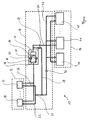
- An embodiment example of the present invention is explained below using the attached figure, in which a cooling system according to the invention is schematically illustrated.
- In the attached figure a cooling system according to the invention is generally designated by 10. It comprises a refrigerating
installation 12, arefrigeration transport system 14 and aregion 16 in which cold is consumed. - The refrigerating
installation 12 has tworefrigeration machines refrigeration transport system 14 via twoparallel pipes refrigeration transport system 14 the twoparallel pipes point 26. Refrigerating agent is conveyed to apump unit 30 via an optional conveyingpipe 28 provided with a separately activatable shut-offvalve 29. Thepump unit 30 has twopumps valves intermediate store 40 is connected upstream the parallel circuit of thepumps pump unit 30. The intermediate store serves to compensate the volume in the event of thermal expansion effects and leakage effects. - Because of the circulating effect of the
pump unit 30, cooled refrigerating agent is conveyed tovarious refrigeration consumers feed pipe 42. Therefrigeration consumers - The cooled refrigerating agent is fed to the
refrigeration consumers feed pipe 42 via single pipes in each case. The refrigerating agent is heated in each of therefrigeration consumers refrigeration consumers refrigeration machines installation 12 through therefrigeration transport system 14 via afeedback pipe 50 by means of thepump unit 30. There the meanwhile heated refrigerating agent is cooled again and can be conducted back into therefrigeration transport system 14 again viapipes - The cooling system can be differently laid out and activated depending on the size of the aircraft and depending on the refrigeration requirement inside the aircraft. It is therefore possible, for example, where a relatively large refrigeration requirement is expected to provide more refrigeration machines, which can then be switched on according to requirement, i.e. in operating situations of high refrigeration requirement, and in operating situations of low refrigeration requirement can be switched to an idle state or completely switched off. It is also possible to continuously control the refrigeration capacity of one of the
refrigeration machines valve 29 into a locked position, so that the entire cooled refrigerating agent is fed to therefrigeration consumers feed pipe 42. In an operating state of low refrigeration requirement, on the other hand, the shut-offvalve 29 is opened, so that part of the cooled refrigerating agent is already conveyed back to therefrigeration machines pump unit 30. - A further possibility for influencing the refrigeration capacity of the
cooling system 10 consists of actuating the circulating pumps 32 and 34 according to requirement. Therefore the speed of thepumps pumps - With the
cooling system 10 it is further possible specifically to open or close the shut-offvalves pumps valves valve 29. This also allows the volume conveyed by the refrigeration transport system to be specifically set. - Activating the
pumps valves refrigeration transport system 14, for example by asensor 52 inpipe 42. - Furthermore, each of the
consumers refrigeration machines pumps valves consumers cooling system 10 and the above mentioned activatable components of thecooling system 10 can be controlled using the measured values. - The invention shows a
cooling system 10 with which a multiplicity ofdifferent refrigeration consumers cooling system 10 can be matched to the current refrigeration requirement. In this way the efficiency in partial load operation, i.e. with relatively low current refrigeration requirement, can be increased. Ultimately this leads to lower consumption of electrical energy inside the aircraft, which also entails reduced fuel consumption of the aircraft.
Claims (16)
- Cooling system (10) for cooling heat-generating installations (44, 46, 48) and for maintaining the temperature of closed-off areas at below cabin temperature in an aircraft, with- a refrigerating installation (12),- at least one refrigeration consumer (44, 46, 48) constructed as a heat-generating installation or as an area to be maintained at a temperature below cabin temperature and- a refrigeration transport system (14) connecting the refrigerating installation (12) and the refrigeration consumer (44, 46, 48),the refrigerating installation (12) comprising at least two refrigeration machines (18, 20) one of which cover the maximum refrigeration requirement of the at least one refrigeration consumer (44, 46, 48) and which operate independently of one another and are coupled to the refrigeration transport system (14) in parallel, wherein the at least one refrigeration consumer (44, 46, 48) being supplied with cold generated in the refrigerating installation (12) via a refrigerating agent circulating in the refrigeration transport system (14), and wherein a central control unit is provided which controls the refrigeration capacity depending on at least one parameter indicating the current refrigeration demand,
characterised in that the refrigeration capacity is controlled by the central control unit switching on and off individual refrigeration machines (18, 20) of the refrigerating installation (12) to match the current refrigeration demand in such a way that on average in terms of time they have substantially the same length of operation. - Cooling system (10) according to claim 1, characterised in that the number of refrigeration machines (18, 20) of the refrigerating installation (12) is chosen in such a way that the refrigeration requirement is covered during ground operation.
- Cooling system (10) according to one of the preceding claims, characterised in that at least one refrigeration machine (18, 20) uses air inside the pressurised fuselage of the aircraft as a heat sink for emitting heat.
- Cooling system (10) according to one of the preceding claims, characterised in that the at least one refrigeration machine (18, 20) generates cold by a vapour cold process.
- Cooling system (10) according to one of the preceding claims, characterised in that the refrigeration transport system (14) has at least one refrigerating agent pump (32, 34) for circulating the refrigerating agent.
- Cooling system (10) according to one of the preceding claims, characterised in that the refrigeration transport system (14) has at least one store (40) for compensating for thermal expansion and leakage losses of the refrigerating agent.
- Cooling system (10) according to one of the preceding claims, characterised in that the at least one refrigeration consumer (44, 46, 48) has a secondary refrigeration transport system in which cold is transmitted from the refrigerating agent by means of a secondary refrigerating agent, preferably air.
- Cooling system (10) according to one of the preceding claims, characterised in that the parameters indicating the current refrigeration demand reproduce the temperature of the refrigerating agent at at least one point in the refrigeration transport system (14) or/and information on the refrigeration demand of the at least one refrigeration consumer (44, 46, 48) or/and the pressure of the refrigerating agent in the refrigeration transport system (14).
- Cooling system (10) according to one of the preceding claims, characterised in that the refrigeration machines are controlled in decentralised manner, in particular by an automatic and time-dependent activation based on a monitoring of the actual status of all refrigeration machines via a databus .
- Cooling system (10) according to claim 9, characterised in that the refrigeration machines are activatable according to a predetermined prioritisation, preferably in varying order.
- Cooling system (10) according to one of the preceding claims, characterised in that the refrigerating agent flows through both a switched on refrigeration machine (18, 20) and a switched off refrigeration machine.
- Cooling system (10) according to one of claims 1 to 10, characterised in that a shut-off valve is assigned to each refrigeration machine.
- Cooling system (10) according to one of the preceding claims, characterised in that the control unit detects the outflow temperature of the refrigerating agent leaving the refrigeration machine (18, 20) and activates the refrigeration machine (18, 20) in accordance with the detected outflow temperature.
- Cooling system (10) according to claim 13, characterised in that the refrigeration capacity of the at least one refrigeration machine (18, 20) can be altered by means of a hot gas bypass valve and/or by varying the speed of a compressor used in the refrigeration machine (18, 20).
- Cooling system (10) according to one of the preceding claims, characterised in that to influence the refrigeration capacity of the cooling system (10) the control unit alters the amount of refrigerating agent conveyed in the refrigeration transport system (14).
- Cooling system (10) according to claim 15, characterised in that to influence the refrigeration capacity the control unit alters the speed of the at least one refrigerating agent pump (32, 34).
Applications Claiming Priority (2)
| Application Number | Priority Date | Filing Date | Title |
|---|---|---|---|
| DE10361686A DE10361686B4 (en) | 2003-12-30 | 2003-12-30 | Cooling system for cooling heat generating equipment in an aircraft |
| PCT/EP2004/014850 WO2005063567A1 (en) | 2003-12-30 | 2004-12-30 | Cooling system for cooling heat-generating installations and for maintaining the temperature of closed-off areas at below cabin temperature in an aircraft |
Publications (2)
| Publication Number | Publication Date |
|---|---|
| EP1704091A1 EP1704091A1 (en) | 2006-09-27 |
| EP1704091B1 true EP1704091B1 (en) | 2009-03-11 |
Family
ID=34716250
Family Applications (1)
| Application Number | Title | Priority Date | Filing Date |
|---|---|---|---|
| EP04804435A Expired - Fee Related EP1704091B1 (en) | 2003-12-30 | 2004-12-30 | Cooling system for cooling heat-generating installations and for maintaining the temperature of closed-off areas at below cabin temperature in an aircraft |
Country Status (9)
| Country | Link |
|---|---|
| US (1) | US7784289B2 (en) |
| EP (1) | EP1704091B1 (en) |
| JP (1) | JP4669481B2 (en) |
| CN (1) | CN1902086B (en) |
| BR (1) | BRPI0418198A (en) |
| CA (1) | CA2553195C (en) |
| DE (2) | DE10361686B4 (en) |
| RU (1) | RU2374140C2 (en) |
| WO (1) | WO2005063567A1 (en) |
Families Citing this family (37)
| Publication number | Priority date | Publication date | Assignee | Title |
|---|---|---|---|---|
| US7380586B2 (en) | 2004-05-10 | 2008-06-03 | Bsst Llc | Climate control system for hybrid vehicles using thermoelectric devices |
| US7743614B2 (en) | 2005-04-08 | 2010-06-29 | Bsst Llc | Thermoelectric-based heating and cooling system |
| DE102005061599A1 (en) * | 2005-12-22 | 2007-06-28 | Airbus Deutschland Gmbh | Modular cooling system and refrigeration device for such a cooling system |
| DE102006017012B4 (en) | 2006-04-11 | 2011-01-13 | Airbus Operations Gmbh | Cooling system and freight container |
| US8118257B2 (en) * | 2006-04-28 | 2012-02-21 | Hamilton Sundstrand Corporation | Thermal management system with staged cooling |
| US20100155018A1 (en) | 2008-12-19 | 2010-06-24 | Lakhi Nandlal Goenka | Hvac system for a hybrid vehicle |
| US7779639B2 (en) * | 2006-08-02 | 2010-08-24 | Bsst Llc | HVAC system for hybrid vehicles using thermoelectric devices |
| WO2008103694A2 (en) * | 2007-02-20 | 2008-08-28 | B/E Aerospace, Inc. | Aircraft galley refrigeration system with multi-circuit heat exchanger |
| DE102007014002B4 (en) | 2007-03-23 | 2012-09-06 | Airbus Operations Gmbh | Cooling system and freight container |
| CN116558147A (en) | 2007-05-25 | 2023-08-08 | 詹思姆公司 | System and method for thermoelectric heating and cooling |
| DE102008023636A1 (en) * | 2008-05-15 | 2009-12-10 | Airbus Deutschland Gmbh | Refrigerated aircraft passenger service facility |
| US8640466B2 (en) | 2008-06-03 | 2014-02-04 | Bsst Llc | Thermoelectric heat pump |
| US20100071881A1 (en) * | 2008-08-21 | 2010-03-25 | Airbus Operations | Cooling system for aircraft electric or electronic devices |
| US9555686B2 (en) | 2008-10-23 | 2017-01-31 | Gentherm Incorporated | Temperature control systems with thermoelectric devices |
| US9447994B2 (en) | 2008-10-23 | 2016-09-20 | Gentherm Incorporated | Temperature control systems with thermoelectric devices |
| WO2010048575A1 (en) | 2008-10-23 | 2010-04-29 | Bsst Llc | Multi-mode hvac system with thermoelectric device |
| US8137355B2 (en) | 2008-12-12 | 2012-03-20 | Zimmer Spine, Inc. | Spinal stabilization installation instrumentation and methods |
| US8137356B2 (en) * | 2008-12-29 | 2012-03-20 | Zimmer Spine, Inc. | Flexible guide for insertion of a vertebral stabilization system |
| CN102576232B (en) | 2009-05-18 | 2015-05-06 | Bsst有限责任公司 | Temperature control system with thermoelectric device |
| KR20170036119A (en) | 2009-05-18 | 2017-03-31 | 젠썸 인코포레이티드 | Battery thermal management system |
| US20110016893A1 (en) * | 2009-07-23 | 2011-01-27 | Warwick Graham Andrew Dawes | Redundant Cooling Method and System |
| CN102639398B (en) * | 2009-09-29 | 2016-01-20 | 空中客车作业有限公司 | For cooling and/or heat the system and method for aircraft devices |
| DE102009053094A1 (en) * | 2009-11-13 | 2011-05-19 | Airbus Operations Gmbh | Control system for controlling cooling system on board of commercial aircraft, has generation unit for generating control signals to control supply of energy to consumers according to operating state signals and priority data in database |
| EP2664543B1 (en) * | 2012-05-16 | 2016-03-23 | Airbus Operations GmbH | Method for operating an aircraft cooling system and aircraft cooling system |
| EP2676881B1 (en) * | 2012-06-21 | 2016-01-06 | Airbus Operations GmbH | Aircraft comprising a cooling system for operation with a two-phase refrigerant |
| EP2815972A1 (en) * | 2013-06-17 | 2014-12-24 | Airbus Operations GmbH | Cargo container comprising a storage rack module and a transport module, vehicle therewith and method of operating thereof |
| US10488075B2 (en) * | 2013-06-18 | 2019-11-26 | B/E Aerospace, Inc. | Apparatus for pre-heating potable water in aircraft with waste heat |
| US10273010B2 (en) * | 2013-09-04 | 2019-04-30 | The Boeing Company | Systems and methods for refrigerating galley compartments |
| CN104315754A (en) * | 2014-11-07 | 2015-01-28 | 北京矿大节能科技有限公司 | Vortex parallel-connecting heat pump unit and starting mode thereof |
| KR20170095952A (en) | 2014-12-19 | 2017-08-23 | 젠썸 인코포레이티드 | Thermal conditioning systems and methods for vehicle regions |
| EP3076109B1 (en) * | 2015-03-30 | 2021-07-07 | Viessmann Refrigeration Solutions GmbH | Cooling system and method for operating the cooling system |
| US9708069B2 (en) * | 2015-04-01 | 2017-07-18 | The Boeing Company | Ram air system and methods of manufacturing the same |
| EP3310471B1 (en) | 2015-06-18 | 2022-12-07 | Uop Llc | Processes and systems for controlling cooling fluid |
| WO2017065847A1 (en) | 2015-10-14 | 2017-04-20 | Gentherm Incorporated | Systems and methods for controlling thermal conditioning of vehicle regions |
| EP3673218A4 (en) * | 2017-08-21 | 2021-01-27 | Optimum Energy, LLC | Systems and methods for reducing energy consumption of a chilled water distribution system |
| DE102018201176A1 (en) * | 2018-01-25 | 2019-07-25 | Siemens Aktiengesellschaft | Galley Air conditioning |
| CN116661526B (en) * | 2023-08-01 | 2023-10-31 | 应急管理部四川消防研究所 | Gas temperature control device and gas temperature control method |
Family Cites Families (20)
| Publication number | Priority date | Publication date | Assignee | Title |
|---|---|---|---|---|
| US3216215A (en) * | 1964-02-27 | 1965-11-09 | Climate Inc | Temperature controlled incubator-hatchers |
| US4191027A (en) * | 1976-07-29 | 1980-03-04 | Kabushiki Kaisah Maekawa Seisakusho | Apparatus for cooling brine |
| US4189929A (en) * | 1978-03-13 | 1980-02-26 | W. A. Brown & Son, Inc. | Air conditioning and dehumidification system |
| US4233817A (en) * | 1978-11-03 | 1980-11-18 | Miles Laboratories, Inc. | Refrigeration apparatus |
| US4487028A (en) * | 1983-09-22 | 1984-12-11 | The Trane Company | Control for a variable capacity temperature conditioning system |
| DE3812739C1 (en) * | 1988-04-16 | 1989-07-06 | Deutsche Lufthansa Ag, 5000 Koeln, De | |
| US5220807A (en) * | 1991-08-27 | 1993-06-22 | Davis Energy Group, Inc. | Combined refrigerator water heater |
| US5423498A (en) * | 1993-04-27 | 1995-06-13 | E-Systems, Inc. | Modular liquid skin heat exchanger |
| DE4340316C2 (en) * | 1993-11-26 | 1996-03-21 | Daimler Benz Aerospace Airbus | Arrangement for cooling food in an aircraft |
| DE4340317C2 (en) | 1993-11-26 | 1996-03-21 | Daimler Benz Aerospace Airbus | Cooling system for cooling food in an airplane |
| DE4439780A1 (en) * | 1994-11-07 | 1996-05-09 | Sep Tech Studien | Compressor chiller |
| CN1143295C (en) * | 1995-04-19 | 2004-03-24 | 索尼公司 | Device for loading disk cartridge |
| US6026652A (en) * | 1996-10-18 | 2000-02-22 | Sanyo Electric Co., Ltd. | Air conditioning system having single bus line |
| US5970731A (en) * | 1997-11-21 | 1999-10-26 | International Business Machines Corporation | Modular refrigeration system |
| JP4023002B2 (en) * | 1998-09-08 | 2007-12-19 | 株式会社島津製作所 | Aircraft cooling system |
| JP4174917B2 (en) * | 1999-06-30 | 2008-11-05 | 株式会社島津製作所 | Cooling system |
| DE19952524A1 (en) * | 1999-10-30 | 2001-05-10 | Eads Airbus Gmbh | Cooling of food and drinks wagons in passenger aircraft is supplied from the cabin air conditioning compressor system into which the heated return air is returned |
| JP4715984B2 (en) * | 2001-04-06 | 2011-07-06 | 株式会社島津製作所 | Cooling system with cool storage function |
| US6880351B2 (en) * | 2001-09-05 | 2005-04-19 | Be Intellectual Property, Inc. | Liquid galley refrigeration system for aircraft |
| DE10361645B4 (en) * | 2003-12-30 | 2008-06-26 | Airbus Deutschland Gmbh | Cooling system for cooling heat generating equipment in an aircraft |
-
2003
- 2003-12-30 DE DE10361686A patent/DE10361686B4/en not_active Expired - Fee Related
-
2004
- 2004-12-30 BR BRPI0418198-0A patent/BRPI0418198A/en not_active Application Discontinuation
- 2004-12-30 CN CN2004800394987A patent/CN1902086B/en not_active Expired - Fee Related
- 2004-12-30 EP EP04804435A patent/EP1704091B1/en not_active Expired - Fee Related
- 2004-12-30 CA CA002553195A patent/CA2553195C/en not_active Expired - Fee Related
- 2004-12-30 US US10/584,901 patent/US7784289B2/en not_active Expired - Fee Related
- 2004-12-30 JP JP2006546115A patent/JP4669481B2/en not_active Expired - Fee Related
- 2004-12-30 WO PCT/EP2004/014850 patent/WO2005063567A1/en active Application Filing
- 2004-12-30 RU RU2006122585/11A patent/RU2374140C2/en not_active IP Right Cessation
- 2004-12-30 DE DE602004019978T patent/DE602004019978D1/en active Active
Also Published As
| Publication number | Publication date |
|---|---|
| US7784289B2 (en) | 2010-08-31 |
| DE10361686B4 (en) | 2008-04-24 |
| CA2553195C (en) | 2009-08-11 |
| JP2007516889A (en) | 2007-06-28 |
| CN1902086B (en) | 2010-11-24 |
| JP4669481B2 (en) | 2011-04-13 |
| CN1902086A (en) | 2007-01-24 |
| RU2374140C2 (en) | 2009-11-27 |
| CA2553195A1 (en) | 2005-07-14 |
| DE602004019978D1 (en) | 2009-04-23 |
| US20080134703A1 (en) | 2008-06-12 |
| BRPI0418198A (en) | 2007-06-19 |
| EP1704091A1 (en) | 2006-09-27 |
| RU2006122585A (en) | 2008-02-10 |
| DE10361686A1 (en) | 2005-08-04 |
| WO2005063567A1 (en) | 2005-07-14 |
Similar Documents
| Publication | Publication Date | Title |
|---|---|---|
| EP1704091B1 (en) | Cooling system for cooling heat-generating installations and for maintaining the temperature of closed-off areas at below cabin temperature in an aircraft | |
| CN100430298C (en) | Cooling system for the cooling of heat-producing devices in an aircraft | |
| RU2403187C2 (en) | Modular refrigerating system and refrigerator for this system | |
| EP1877712B1 (en) | Refrigerator-oven combination for an aircraft galley food service system | |
| EP2004487B1 (en) | Cooling system and arrangement comprising a cooling system and a freight container | |
| EP2688758B1 (en) | Apparatus and method for operating a refrigeration system having two or more chambers | |
| JP2009525453A (en) | Cooling system | |
| JP2007516889A5 (en) | ||
| RU2459747C2 (en) | Cooling system and cargo container | |
| US9272788B2 (en) | Aircraft cooling system and method for operating an aircraft cooling system | |
| US11199354B2 (en) | Refrigeration unit having an accumulator, refrigeration system and method for controlling a refrigeration unit having an accumulator | |
| CN103373469B (en) | Method and the aircraft of aircraft thermal control system, operation thermal control system | |
| EP2664543B1 (en) | Method for operating an aircraft cooling system and aircraft cooling system | |
| EP2631567A1 (en) | Cooling system with a plurality of super-coolers |
Legal Events
| Date | Code | Title | Description |
|---|---|---|---|
| PUAI | Public reference made under article 153(3) epc to a published international application that has entered the european phase |
Free format text: ORIGINAL CODE: 0009012 |
|
| 17P | Request for examination filed |
Effective date: 20060621 |
|
| AK | Designated contracting states |
Kind code of ref document: A1 Designated state(s): DE ES FR GB IT SE |
|
| DAX | Request for extension of the european patent (deleted) | ||
| RBV | Designated contracting states (corrected) |
Designated state(s): DE ES FR GB IT SE |
|
| 17Q | First examination report despatched |
Effective date: 20070605 |
|
| GRAP | Despatch of communication of intention to grant a patent |
Free format text: ORIGINAL CODE: EPIDOSNIGR1 |
|
| GRAS | Grant fee paid |
Free format text: ORIGINAL CODE: EPIDOSNIGR3 |
|
| GRAA | (expected) grant |
Free format text: ORIGINAL CODE: 0009210 |
|
| AK | Designated contracting states |
Kind code of ref document: B1 Designated state(s): DE ES FR GB IT SE |
|
| REG | Reference to a national code |
Ref country code: GB Ref legal event code: FG4D |
|
| REF | Corresponds to: |
Ref document number: 602004019978 Country of ref document: DE Date of ref document: 20090423 Kind code of ref document: P |
|
| REG | Reference to a national code |
Ref country code: SE Ref legal event code: TRGR |
|
| PG25 | Lapsed in a contracting state [announced via postgrant information from national office to epo] |
Ref country code: ES Free format text: LAPSE BECAUSE OF FAILURE TO SUBMIT A TRANSLATION OF THE DESCRIPTION OR TO PAY THE FEE WITHIN THE PRESCRIBED TIME-LIMIT Effective date: 20090622 |
|
| PLBE | No opposition filed within time limit |
Free format text: ORIGINAL CODE: 0009261 |
|
| STAA | Information on the status of an ep patent application or granted ep patent |
Free format text: STATUS: NO OPPOSITION FILED WITHIN TIME LIMIT |
|
| 26N | No opposition filed |
Effective date: 20091214 |
|
| REG | Reference to a national code |
Ref country code: FR Ref legal event code: CD Owner name: AIRBUS OPERATIONS GMBH Effective date: 20111118 |
|
| REG | Reference to a national code |
Ref country code: FR Ref legal event code: PLFP Year of fee payment: 12 |
|
| PGFP | Annual fee paid to national office [announced via postgrant information from national office to epo] |
Ref country code: IT Payment date: 20151228 Year of fee payment: 12 |
|
| REG | Reference to a national code |
Ref country code: FR Ref legal event code: PLFP Year of fee payment: 13 |
|
| PGFP | Annual fee paid to national office [announced via postgrant information from national office to epo] |
Ref country code: DE Payment date: 20161213 Year of fee payment: 13 Ref country code: GB Payment date: 20161222 Year of fee payment: 13 |
|
| PGFP | Annual fee paid to national office [announced via postgrant information from national office to epo] |
Ref country code: FR Payment date: 20161222 Year of fee payment: 13 Ref country code: SE Payment date: 20161221 Year of fee payment: 13 |
|
| PG25 | Lapsed in a contracting state [announced via postgrant information from national office to epo] |
Ref country code: IT Free format text: LAPSE BECAUSE OF NON-PAYMENT OF DUE FEES Effective date: 20161230 |
|
| REG | Reference to a national code |
Ref country code: DE Ref legal event code: R119 Ref document number: 602004019978 Country of ref document: DE |
|
| GBPC | Gb: european patent ceased through non-payment of renewal fee |
Effective date: 20171230 |
|
| PG25 | Lapsed in a contracting state [announced via postgrant information from national office to epo] |
Ref country code: SE Free format text: LAPSE BECAUSE OF NON-PAYMENT OF DUE FEES Effective date: 20171231 |
|
| REG | Reference to a national code |
Ref country code: FR Ref legal event code: ST Effective date: 20180831 |
|
| PG25 | Lapsed in a contracting state [announced via postgrant information from national office to epo] |
Ref country code: DE Free format text: LAPSE BECAUSE OF NON-PAYMENT OF DUE FEES Effective date: 20180703 Ref country code: FR Free format text: LAPSE BECAUSE OF NON-PAYMENT OF DUE FEES Effective date: 20180102 |
|
| PG25 | Lapsed in a contracting state [announced via postgrant information from national office to epo] |
Ref country code: GB Free format text: LAPSE BECAUSE OF NON-PAYMENT OF DUE FEES Effective date: 20171230 |