EP1703592B1 - Antennendose mit mittels eines Radialtaumelnietvorganges festgelegter Leiterplatte - Google Patents
Antennendose mit mittels eines Radialtaumelnietvorganges festgelegter Leiterplatte Download PDFInfo
- Publication number
- EP1703592B1 EP1703592B1 EP06003984A EP06003984A EP1703592B1 EP 1703592 B1 EP1703592 B1 EP 1703592B1 EP 06003984 A EP06003984 A EP 06003984A EP 06003984 A EP06003984 A EP 06003984A EP 1703592 B1 EP1703592 B1 EP 1703592B1
- Authority
- EP
- European Patent Office
- Prior art keywords
- circuit board
- printed circuit
- base plate
- antenna socket
- studs
- Prior art date
- Legal status (The legal status is an assumption and is not a legal conclusion. Google has not performed a legal analysis and makes no representation as to the accuracy of the status listed.)
- Expired - Lifetime
Links
Images


Classifications
-
- H—ELECTRICITY
- H01—ELECTRIC ELEMENTS
- H01R—ELECTRICALLY-CONDUCTIVE CONNECTIONS; STRUCTURAL ASSOCIATIONS OF A PLURALITY OF MUTUALLY-INSULATED ELECTRICAL CONNECTING ELEMENTS; COUPLING DEVICES; CURRENT COLLECTORS
- H01R4/00—Electrically-conductive connections between two or more conductive members in direct contact, i.e. touching one another; Means for effecting or maintaining such contact; Electrically-conductive connections having two or more spaced connecting locations for conductors and using contact members penetrating insulation
- H01R4/06—Riveted connections
-
- H—ELECTRICITY
- H01—ELECTRIC ELEMENTS
- H01R—ELECTRICALLY-CONDUCTIVE CONNECTIONS; STRUCTURAL ASSOCIATIONS OF A PLURALITY OF MUTUALLY-INSULATED ELECTRICAL CONNECTING ELEMENTS; COUPLING DEVICES; CURRENT COLLECTORS
- H01R13/00—Details of coupling devices of the kinds covered by groups H01R12/70 or H01R24/00 - H01R33/00
- H01R13/66—Structural association with built-in electrical component
- H01R13/665—Structural association with built-in electrical component with built-in electronic circuit
- H01R13/6658—Structural association with built-in electrical component with built-in electronic circuit on printed circuit board
-
- H—ELECTRICITY
- H01—ELECTRIC ELEMENTS
- H01R—ELECTRICALLY-CONDUCTIVE CONNECTIONS; STRUCTURAL ASSOCIATIONS OF A PLURALITY OF MUTUALLY-INSULATED ELECTRICAL CONNECTING ELEMENTS; COUPLING DEVICES; CURRENT COLLECTORS
- H01R24/00—Two-part coupling devices, or either of their cooperating parts, characterised by their overall structure
- H01R24/38—Two-part coupling devices, or either of their cooperating parts, characterised by their overall structure having concentrically or coaxially arranged contacts
- H01R24/40—Two-part coupling devices, or either of their cooperating parts, characterised by their overall structure having concentrically or coaxially arranged contacts specially adapted for high frequency
- H01R24/52—Two-part coupling devices, or either of their cooperating parts, characterised by their overall structure having concentrically or coaxially arranged contacts specially adapted for high frequency mounted in or to a panel or structure
- H01R24/525—Outlets
-
- H—ELECTRICITY
- H01—ELECTRIC ELEMENTS
- H01R—ELECTRICALLY-CONDUCTIVE CONNECTIONS; STRUCTURAL ASSOCIATIONS OF A PLURALITY OF MUTUALLY-INSULATED ELECTRICAL CONNECTING ELEMENTS; COUPLING DEVICES; CURRENT COLLECTORS
- H01R43/00—Apparatus or processes specially adapted for manufacturing, assembling, maintaining, or repairing of line connectors or current collectors or for joining electric conductors
-
- H—ELECTRICITY
- H01—ELECTRIC ELEMENTS
- H01R—ELECTRICALLY-CONDUCTIVE CONNECTIONS; STRUCTURAL ASSOCIATIONS OF A PLURALITY OF MUTUALLY-INSULATED ELECTRICAL CONNECTING ELEMENTS; COUPLING DEVICES; CURRENT COLLECTORS
- H01R13/00—Details of coupling devices of the kinds covered by groups H01R12/70 or H01R24/00 - H01R33/00
- H01R13/648—Protective earth or shield arrangements on coupling devices, e.g. anti-static shielding
- H01R13/658—High frequency shielding arrangements, e.g. against EMI [Electro-Magnetic Interference] or EMP [Electro-Magnetic Pulse]
- H01R13/6581—Shield structure
-
- H—ELECTRICITY
- H01—ELECTRIC ELEMENTS
- H01R—ELECTRICALLY-CONDUCTIVE CONNECTIONS; STRUCTURAL ASSOCIATIONS OF A PLURALITY OF MUTUALLY-INSULATED ELECTRICAL CONNECTING ELEMENTS; COUPLING DEVICES; CURRENT COLLECTORS
- H01R2107/00—Four or more poles
Definitions
- the invention relates to an antenna socket for the connection of high-frequency equipment with a main body according to the features of the preamble of claim 1.
- Antenna boxes usually for installation in a flush box, are generally known. These have a base body with connection means to which high frequency equipment such as TVs, radios, modems and the like can be connected. Within the body further connection means are present in which the high-frequency signals are supplied via coaxial cables or other types of lines and connected to the antenna box. Due to today's requirements for antenna doses, it is necessary to edit the supplied high-frequency signals yet, including the base body of the antenna box still receives at least one circuit board with components for the realization of the function. This printed circuit board must be fixed permanently and electrically contacting the main body for shielding purposes. For this purpose, it has been proposed to provide the circuit board with openings, which are guided by the openings screws that are screwed into the body.
- pins are arranged on the base body, which engage in openings of the circuit board, wherein the upper end of the pins to solder after mounting the circuit board with electrically conductive areas around the openings of the circuit board around.
- the soldering process causes problems when the base body of the antenna box consists of a die-cast material, since the required heating of the pins very high temperatures are necessary, which, however, adversely affect the components which are arranged on the circuit board again. In addition, it is problematic that the pins made of die-cast material are not readily solderable.
- the invention is therefore based on the object to provide an antenna socket for the connection of high-frequency equipment, with the above-described disadvantages are avoided, in particular the shielding effect is to be improved arranged on a printed circuit board components and the manufacturing process of the antenna box simplified.
- pins are arranged on the base body, which engage in openings of the printed circuit board after assembly of the printed circuit board and whose upper end are deformed by a Radialtaumelnietvorgang for fixing the position of the circuit board to the base body.
- the printed circuit board with openings is available (in particular after being fitted with electrical and / or electronic components), it can simply be inserted into a corresponding recess in the base body, so that erroneous positioning of the printed circuit board in the antenna socket can be achieved by the guidance by means of the pins or tilting during insertion is avoided. After this assembly, it is still necessary to fix the circuit board in position on the base body, to which a Radialtaumelnietvorgang is performed. This process has the particular advantage that it can be automated and thus can be executed quickly and above all evenly. This uniformity of the attachment causes advantageously that the circuit board can be fixed in the desired position on the body, without causing tension, which could lead to conductor breaks on the circuit board.
- the base body is advantageously formed as a die-cast component to which the pins for the attachment of the circuit board are already formed after the production in the die-casting.
- the base body is still a die-cast component, but after its manufacture has openings into which pins are inserted.
- This embodiment may be advantageous if the contact resistance of the conductive areas of the circuit board on the usable pins to the base body to be optimized by different materials.
- the electrically conductive regions are usually made of copper, while the base body consists of a gray cast iron material or a steel material.
- the pins may be made of another material (such as brass).
- the Radialtaumelnietvorgang can be optimally adapted to the material of the pins, if they are made of a material other than gray cast iron.
- Figure 1 shows a three-dimensional view of an antenna socket 1, which is designed for use in a flush-mounted box and for this purpose has corresponding claws for attachment.
- a base body 2 which is preferably a Druckgußbauteil around, a frame is provided which has openings to screw the antenna box in a receiving device can, when the claws are not used.
- connecting means 3 to 5 are provided, which are screwable and / or plug-in connection means.
- connection means 3 to 5 are provided, which are screwable and / or plug-in connection means.
- connection means 3 to 5 the connection of high-frequency facilities, such as television or radio, modems or the like.
- connection means 3 to 5 Approximately in the middle region between the connection means 3 to 5 further, not provided with reference numerals connection means are provided, at which the supply lines which supply the high-frequency signals to the antenna socket 1, are connected.
- the main body 2 In the rear region of the main body 2, ie behind the connection means, the main body 2 has a receptacle for at least one printed circuit board, which is not shown here and is equipped with electrical and / or electronic components. This circuit board is connected at a suitable location with the connection means 3 to 5 and the connection means for the one or more cables.
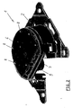
- FIG. 2 shows the rear view of the main body 2 of the antenna socket 1, wherein it can be seen that a printed circuit board 6 is inserted approximately coaxially within the outer edge of the main body 2.
- the main body 2 may have an at least partially, in particular complete circumferential shoulder 7.
- the printed circuit board 6 After the printed circuit board 6 has been equipped with the components and provided with openings on the edge, it is mounted on the back of the base body 2, in particular within the peripheral paragraph 7.
- the openings in the circuit board 6 correspond to several pins 8, previously in the main body 2 have been used and / or are integrally formed on the base body 2.
- the printed circuit board 6 is located on domes 9, from which the pins 8 protrude and are preferably part of the dome 9.
- the inner contour of the main body 2 corresponds substantially to the outer contour of the printed circuit board 6, wherein these contours can be shaped so that the printed circuit board 6 can be fastened to the main body 2 only in a single position (coding).
- the pins 8 are present on the base body 2, that one or more printed circuit boards 6 or even a circuit board, but then in various forms, can be attached.
- Figure 3 shows a section AA through the antenna box 1 according to Figure 1, wherein the design of the base body 2 with its peripheral shoulder 7 and the inserted or molded pins 8 can be seen.
- These pins 8 have a cylindrical shape prior to assembly of the printed circuit board 6 and project from the underside of the main body 2 or from the shoulder 7 or from the domes 9. After assembly of the printed circuit board 6, this is used on the back of the base body 2 and comes with its underside on the domes 9 (or alternatively or in addition to the base body 2 and on the paragraph 7) to the plant. Subsequently, a machining of the upper end of the pins 8 by a Radialtaumelnietvorgang, said upper end is deformed approximately mushroom-shaped. This deformation is indicated in FIG.
- the base body 2 can be produced by die casting, the areas of the circuit board 6, the pins 8, the dome 9 and the base body 2, in which an electrical contact for the purpose of shielding should take place, optimally and precisely matched to each other, so that after Implementation of the Radialtaumelnietvorganges a on all pins 8 almost the same contact (in particular the same contact resistance) is realized, the post-processing, for. B. in the form of a soldering process, dispensable. In addition, basically no further processing, such as screwing, soldering or the like are required for fixing the position of the circuit board 6 on the base body 2.
Landscapes
- Engineering & Computer Science (AREA)
- Microelectronics & Electronic Packaging (AREA)
- Manufacturing & Machinery (AREA)
- Coupling Device And Connection With Printed Circuit (AREA)
- Support Of Aerials (AREA)
- Shielding Devices Or Components To Electric Or Magnetic Fields (AREA)
- Variable-Direction Aerials And Aerial Arrays (AREA)
- Multi-Conductor Connections (AREA)
Description
- Die Erfindung betrifft eine Antennendose für den Anschluss hochfrequenztechnischer Einrichtungen mit einem Grundkörper gemäß den Merkmalen des Oberbegriffes des Patentanspruchs 1.
- Antennendosen, meistens zum Einbau in eine Unterputzdose, sind grundsätzlich bekannt. Diese weisen einen Grundkörper mit Anschlussmitteln auf, an die hochfrequenztechnische Einrichtungen, wie Fernseher, Rundfunkgeräte, Modems und dergleichen angeschlossen werden können. Innerhalb des Grundkörpers sind weitere Anschlussmittel vorhanden, in denen die Hochfrequenzsignale über Koaxialleitungen oder andere Arten von Leitungen zugeführt und an der Antennendose angeschlossen werden. Aufgrund heutiger Anforderungen an Antennendosen ist es erforderlich, die zugeführten Hochfrequenzsignale noch zu bearbeiten, wozu der Grundkörper der Antennendose noch zumindest eine Leiterplatte mit Bauteilen zur Realisierung der Funktion aufnimmt. Diese Leiterplatte muss dauerhaft und zu Abschirmzwecken elektrisch kontaktierend an dem Grundkörper festgelegt werden. Hierzu ist schon vorgeschlagen worden, die Leiterplatte mit Öffnungen zu versehen, wobei durch die Öffnungen Schrauben geführt werden, die in den Grundkörper eingeschraubt werden. Soll die Leiterplatte nur zu Befestigungszwecken mit den Schrauben verschraubt werden, ist es von Nachteil, dass der Montagevorgang (Eindrehen) der Schrauben aufwändig ist und die Teilevielfalt sehr hoch ist. Zur sicheren Befestigung der Leiterplatte an dem Grundkörper sind nämlich meistens vier oder mehr Schrauben erforderlich. Ist auch noch eine Abschirmung gewünscht (Massekontaktierung zwischen der Leiterplatte und dem Grundkörper) kommt es aufgrund unterschiedlicher Anzugskräfte der Schrauben zu unterschiedlichen Abschirmungspegeln, die unerwünscht sind. Um diese unerwünschten Abschirmungspegel auszugleichen, ist es erforderlich, die Antennendose auf einem Prüfplatz auszumessen und durch nachträgliches Anziehen oder Lösen der Schrauben die Abschirmung zu vergleichmäßigen.
- In einer anderen Ausführungsform einer bekannten Antennendose (siehe beispielsweise
DE 9212510 U ) ist schon vorgeschlagen worden, dass an dem Grundkörper Stifte angeordnet sind, die in Öffnungen der Leiterplatte eingreifen, wobei das obere Ende der Stifte nach der Montage der Leiterplatte mit elektrisch leitfähigen Bereichen um die Öffnungen der Leiterplatte herum zu verlöten. Damit läßt sich zwar die Wirkung der Abschirmung vergleichmäßigen, ist aber immer noch nicht optimal, da mittels der jeweiligen Lötvorgänge an den einzelnen Stiften immer noch nicht sichergestellt werden kann, dass die elektrische Kontaktierung (insbesondere deren Übergangswiderstand) an allen Befestigungspunkten gleichmäßig ist. Außerdem bereitet der Lötvorgang dann Probleme, wenn der Grundkörper der Antennendose aus einem Druckgußmaterial besteht, da zur erforderlichen Erhitzung der Stifte sehr hohe Temperaturen nötig sind, die sich allerdings wieder nachteilig auf die Bauteile, die auf der Leiterplatte angeordnet sind, auswirken. Daneben ist es problematisch, dass die Stifte aus Druckgußmaterial nicht ohne weiteres lötbar sind. - Der Erfindung liegt daher die Aufgabe zugrunde, eine Antennendose für den Anschluss hochfrequenztechnischer Einrichtungen bereitzustellen, mit der die eingangs geschilderten Nachteile vermieden werden, insbesondere soll die Abschirmwirkung für auf einer Leiterplatte angeordnete Bauteile verbessert und der Herstellprozess der Antennendose vereinfacht werden.
- Diese Aufgabe ist durch die Merkmale des Patentanspruchs 1 gelöst.
- Erfindungsgemäß ist vorgesehen, dass an dem Grundkörper Stifte angeordnet sind, die nach der Montage der Leiterplatte in Öffnungen der Leiterplatte eingreifen und deren oberes Ende durch einen Radialtaumelnietvorgang zur Lagefixierung der Leiterplatte an dem Grundkörper verformt werden. Das Grundprinzip, dass die Leiterplatte Öffnungen aufweist, in die Stifte eingreifen, die an dem Grundkörper angeordnet sind, wird beibehalten, da die betroffenen Elemente sehr einfach herstellbar sind und auch die Montage vereinfacht wird. Steht nämlich die Leiterplatte mit Öffnungen zur Verfügung (insbesondere nach ihrer Bestückung mit elektrischen und/oder elektronischen Bauteilen) kann diese einfach in eine entsprechende Aussparung in dem Grundkörper eingesetzt werden, so dass durch die Führung mittels der Stifte eine fehlerhafte Positionierung der Leiterplatte in der Antennendose oder ein Verkanten beim Einsetzen vermieden wird. Nach dieser Montage ist es noch erforderlich, die Leiterplatte in ihrer Lage am Grundkörper zu fixieren, wozu ein Radialtaumelnietvorgang ausgeführt wird. Dieser Vorgang hat den besonderen Vorteil, dass er automatisierbar ist und damit schnell und vor allen Dingen gleichmäßig ausgeführt werden kann. Diese Gleichmäßigkeit der Befestigung bewirkt in vorteilhafter Weise, dass die Leiterplatte in der gewünschten Position an dem Grundkörper festgelegt werden kann, ohne dass es zu Verspannungen kommt, die zu Leiterbahnunterbrechungen auf der Leiterplatte führen könnten. Außerdem entfallen weitere Einzelteile in dem Fall, in dem die Stifte schon an dem Grundkörper angeformt sind. In diesem Fall ist der Grundkörper in vorteilhafter Weise als Druckgußbauteil ausgebildet, an dem nach der Herstellung im Druckgußverfahren die Stifte für die Befestigung der Leiterplatte schon angeformt sind. Alternativ oder ergänzend dazu kann es auch denkbar sein, dass der Grundkörper nach wie vor ein Druckgußbauteil ist, aber nach seiner Herstellung Öffnungen aufweist, in die Stifte eingesetzt werden. Diese Ausführung kann dann von Vorteil sein, wenn der Übergangswiderstand von den leitfähigen Bereichen der Leiterplatte über die einsetzbaren Stifte bis hin zu dem Grundkörper durch unterschiedliche Materialien optimiert werden sollen. So bestehen die elektrisch leitfähigen Bereiche im Regelfall aus Kupfer, während der Grundkörper aus einem Graugußmaterial oder einem Stahlmaterial besteht. Zur Optimierung der Spannungsreihen, die zur Verbesserung der Übergangswiderstände führen, können die Stifte beispielsweise aus einem anderen Material (wie beispielsweise Messing) bestehen. Außerdem kann der Radialtaumelnietvorgang optimal auf das Material der Stifte abgestimmt werden, wenn diese aus einem anderen Material als Grauguß bestehen. Das separate Einsetzen von Stiften in Öffnungen in den Grundkörper erhöht zwar die Teilezahl und den Montageaufwand, was jedoch dann nicht von Nachteil ist, wenn dieser Vorgang automatisiert ausgeführt wird, wobei vor allen Dingen der wesentliche Vorteil des Radialtaumelnietvorganges beibehalten wird.
- Ein Ausführungsbeispiel, auf das die Erfindung jedoch nicht beschränkt ist, ist im Folgenden beschrieben und anhand der Figuren erläutert.
- Es zeigen:
- Figur 1
- dreidimensionale Ansicht einer Antennendose,
- Figur 2
- Rückansicht auf einen Grundkörper der Antennendose gemäß Figur 1,
- Figur 3
- Schnitt durch die Antennendose gemäß Figur 1.
- Figur 1 zeigt in dreidimensionaler Ansicht eine Antennendose 1, die zum Einsatz in eine Unterputzdose ausgebildet ist und hierfür entsprechende Krallen zur Befestigung aufweist. Um einen Grundkörper 2, der vorzugsweise ein Druckgußbauteil ist, herum, ist ein Rahmen vorgesehen, der Öffnungen aufweist, um die Antennendose in einer Aufnahmevorrichtung festschrauben zu können, wenn die Krallen nicht zum Einsatz kommen. Innerhalb des Grundkörpers 2 sind Anschlussmittel 3 bis 5 vorgesehen, bei denen es sich um schraubbare und/oder steckbare Anschlussmittel handelt. An diesen Anschlussmitteln 3 bis 5 erfolgt der Anschluss hochfrequenztechnischer Einrichtungen, wie Fernseh- oder Rundfunkgeräte, Modems oder dergleichen. In etwa im Mittenbereich zwischen den Anschlussmitteln 3 bis 5 sind weitere, nicht mit Bezugsziffern versehende Anschlussmittel vorgesehen, an denen die Zuführleitungen, die die hochfrequenten Signale an die Antennendose 1 liefern, angeschlossen werden. Im Rückbereich des Grundkörpers 2, also hinter den Anschlussmitteln, weist der Grundkörper 2 eine Aufnahme für zumindest eine Leiterplatte auf, die hier nicht dargestellt ist und mit elektrischen und/oder elektronischen Bauteilen bestückt ist. Diese Leiterplatte wird an geeigneter Stelle mit den Anschlussmitteln 3 bis 5 sowie den Anschlussmitteln für das eine oder die mehreren Kabel verbunden.
- Figur 2 zeigt die Rückansicht des Grundkörpers 2 der Antennendose 1, wobei erkennbar ist, dass etwa koaxial innerhalb des äußeren Randes des Grundkörpers 2 eine Leiterplatte 6 eingesetzt ist. Zur Aufnahme der Leiterplatte 6 kann der Grundkörper 2 einen zumindest teilweise, insbesondere vollständigen umlaufenden Absatz 7 aufweisen. Nachdem die Leiterplatte 6 mit den Bauteilen bestückt und mit Öffnungen am Rand versehen worden ist, wird diese auf der Rückseite des Grundkörpers 2 montiert, insbesondere innerhalb des umlaufenden Absatzes 7. Die Öffnungen in der Leiterplatte 6 korrespondieren dabei mit mehreren Stiften 8, die vorher in den Grundkörper 2 eingesetzt wurden und/oder an dem Grundkörper 2 angeformt sind. Bei dieser Ausführungsform liegt die Leiterplatte 6 auf Domen 9 auf, aus denen die Stifte 8 herausragen und vorzugsweise Bestandteil der Dome 9 sind. Zusätzlich kann die Leiterplatte 6 aber auch auf dem Absatz 7 (zumindest teilweise) aufliegen. Die Innenkontur des Grundkörpers 2 entspricht dabei im Wesentlichen der Außenkontur der Leiterplatte 6, wobei diese Konturen so geformt sein können, dass die Leiterplatte 6 nur in einer einzigen Position an dem Grundkörper 2 befestigbar ist (Codierung). Außerdem ist es denkbar, dass die Stifte 8 so an dem Grundkörper 2 vorhanden sind, dass eine oder auch mehrere Leiterplatten 6 oder auch nur eine Leiterplatte, dann aber in verschiedenen Formen, befestigt werden können.
- Figur 3 zeigt einen Schnitt A-A durch die Antennendose 1 gemäß Figur 1, wobei die Ausgestaltung des Grundkörpers 2 mit seinem umlaufenden Absatz 7 und den eingesetzten oder angeformten Stiften 8 erkennbar ist. Diese Stifte 8 weisen vor der Montage der Leiterplatte 6 eine zylindrische Form auf und stehen von der Unterseite des Grundkörpers 2 bzw. von dem Absatz 7 bzw. von den Domen 9 ab. Nach Bestückung der Leiterplatte 6 wird diese auf der Rückseite des Grundkörpers 2 eingesetzt und kommt mit ihrer Unterseite auf den Domen 9 (oder alternative oder ergänzend an dem Grundkörper 2 bzw. auf dem Absatz 7) zur Anlage. Anschließend erfolgt eine Bearbeitung des oberen Endes der Stifte 8 durch einen Radialtaumelnietvorgang, wobei dieses obere Ende in etwa pilzkopfförmig verformt wird. Diese Verformung ist in Figur 3 (rechte Darstellung) angedeutet. Nach Durchführung des vollständigen Radialtaumelhietvorganges liegt die Leiterplatte 6 mit ihrer Unterseite auf den Domen 9 (und/oder der Oberseite des Absatzes 7 oder in sonstiger Weise auf dem Grundkörper 2) auf. Zumindest im Bereich der pilzkopfförmigen verformten Stifte 8 weist die Leiterplatte 6 in diesem Bereich der Öffnung um diese Öffnung herum einen elektrisch leitfähigen Bereich auf, so dass eine Kontaktierung zwischen diesem Bereich über die Stifte 8 in den Grundkörper 2 gegeben ist, um eine Abschirmung herzustellen. Da der Grundkörper 2 im Druckgußverfahren hergestellt werden kann, können die Bereiche der Leiterplatte 6, der Stifte 8, der Dome 9 und des Grundkörpers 2, in denen eine elektrische Kontaktierung zwecks Abschirmung stattfinden soll, optimal und präzise aufeinander abgestimmt werden, so dass nach der Durchführung des Radialtaumelnietvorganges eine an allen Stiften 8 nahezu gleiche Kontaktierung (insbesondere gleicher Übergangswiderstand) realisiert ist, der eine Nachbearbeitung, z. B. in Form von einem Lötvorgang, entbehrlich macht. Außerdem sind grundsätzlich zur Lagefixierung der Leiterplatte 6 an dem Grundkörper 2 keine weiteren Bearbeitungen, wie Verschraubungen, Verlötungen oder dergleichen erforderlich.
-
- 1
- Antennendose
- 2
- Grundkörper
- 3-5
- Anschlußmittel
- 6
- Leiterplatte
- 7
- Absatz
- 8
- Stifte
- 9
- Dome
Claims (7)
- Antennendose (1) für den Anschluss hochfrequenztechnischer Einrichtungen, die einen Grundkörper (2) mit Anschlussmitteln (3 bis 5) aufweist, wobei an dem Grundkörper (2) zumindest eine Leiterplatte (6) befestigbar ist, wobei an dem Grundkörper (2) Stifte (8) angeordnet sind, die nach der Montage der Leiterplatte (6) in Öffnungen der Leiterplatte (6) eingreifen, dadurch gekennzeichnet, dass ein oberes Ende der Stifte durch einen Radialtaumelnietvorgang zur Lagefixierung der Leiterplatte (6) an dem Grundkörper (2) verformt wird.
- Antennendose (1) nach Anspruch 1, dadurch gekennzeichnet, dass der Grundkörper (2) einen zumindest teilweise, insbesondere vollständig umlaufenden Absatz (7) aufweist, wobei die Stifte (8) von dem Absatz (7) abstehend an diesem angeformt sind.
- Antennendose (1) nach Anspruch 1 oder 2, dadurch gekennzeichnet, dass die Stifte (8) an dem Grundkörper (2) angeformt sind.
- Antennendose (1) nach Anspruch 1 oder 2, dadurch gekennzeichnet, dass die Stifte (8) in Öffnungen in den Grundkörper (2) eingesetzt sind.
- Antennendose (1) nach einem der vorhergehenden Ansprüche, dadurch gekennzeichnet, dass der Grundkörper (2) ein Druckgußbauteil ist.
- Antennendose (1) nach einem der vorhergehenden Ansprüche, dadurch gekennzeichnet, dass um die Öffnungen in der Leiterplatte (6) herum auf zumindest einer Seite der Leiterplatte (6), insbesondere auf beiden Seiten der Leiterplatte (6), ein elektrisch leitfähiger Bereich vorhanden ist.
- Antennendose (1) nach einem der vorhergehenden Ansprüche, dadurch gekennzeichnet, dass der Grundkörper (2) zur Aufnahme von Leiterplatten (6) unterschiedlicher Größe ausgebildet ist.
Applications Claiming Priority (2)
| Application Number | Priority Date | Filing Date | Title |
|---|---|---|---|
| DE102005012477 | 2005-03-16 | ||
| DE200510043135 DE102005043135A1 (de) | 2005-09-12 | 2005-09-12 | Antennendose mit mittels eines Radialtaumelnietvorganges festgelegter Leiterplatte |
Publications (2)
| Publication Number | Publication Date |
|---|---|
| EP1703592A1 EP1703592A1 (de) | 2006-09-20 |
| EP1703592B1 true EP1703592B1 (de) | 2007-10-03 |
Family
ID=36143311
Family Applications (1)
| Application Number | Title | Priority Date | Filing Date |
|---|---|---|---|
| EP06003984A Expired - Lifetime EP1703592B1 (de) | 2005-03-16 | 2006-02-27 | Antennendose mit mittels eines Radialtaumelnietvorganges festgelegter Leiterplatte |
Country Status (4)
| Country | Link |
|---|---|
| EP (1) | EP1703592B1 (de) |
| AT (1) | ATE375017T1 (de) |
| DE (1) | DE502006000116D1 (de) |
| ES (1) | ES2294747T3 (de) |
Family Cites Families (3)
| Publication number | Priority date | Publication date | Assignee | Title |
|---|---|---|---|---|
| DE3530722A1 (de) * | 1985-08-28 | 1987-03-05 | Kolbe & Co Hans | Antennensteckdose |
| DE9212510U1 (de) * | 1992-09-17 | 1992-11-05 | Richard Hirschmann GmbH & Co, 7300 Esslingen | Koaxialer Gerätesteckverbinder |
| FI114848B (fi) * | 1997-11-25 | 2004-12-31 | Filtronic Lk Oy | Runkorakenne, laite ja menetelmä laitteen valmistamiseksi |
-
2006
- 2006-02-27 ES ES06003984T patent/ES2294747T3/es not_active Expired - Lifetime
- 2006-02-27 AT AT06003984T patent/ATE375017T1/de not_active IP Right Cessation
- 2006-02-27 DE DE502006000116T patent/DE502006000116D1/de not_active Expired - Lifetime
- 2006-02-27 EP EP06003984A patent/EP1703592B1/de not_active Expired - Lifetime
Also Published As
| Publication number | Publication date |
|---|---|
| ATE375017T1 (de) | 2007-10-15 |
| ES2294747T3 (es) | 2008-04-01 |
| DE502006000116D1 (de) | 2007-11-15 |
| EP1703592A1 (de) | 2006-09-20 |
Similar Documents
| Publication | Publication Date | Title |
|---|---|---|
| EP0906008B1 (de) | Kunststoffgehäuse zur Aufnahme einer elektrischen Leiterplatte | |
| DE102004017371A1 (de) | Antennenvorrichtung für ein Fahrzeug mit einem als Rastelement ausgebildetem Befestigungselement | |
| EP0247662A1 (de) | Durchführungsanschluss für HF-Signale | |
| EP3143664A1 (de) | Mobilfunkantenne | |
| DE69712850T2 (de) | Vorrichtung zur mechanischen und elektrischen Verbindung von zwei Teilbaugruppen eines Kraftfahrzeugwechselstromgenerators | |
| EP1561257A1 (de) | Verbindungseinrichtung zum anschluss zumindest zweier versetzt zueinander angeordneter strahlereinrichtungen einer antennenanordnung | |
| EP1709711B1 (de) | Vorrichtung zum anschluss eines koaxialkabels an ein gehäuse | |
| DE102011108937A1 (de) | Hochstromkontaktelement für Leiterplatten | |
| DE102012021323A1 (de) | Formgebungsverfahren | |
| EP1646106A1 (de) | Steckanordnung für HF-Signalweg | |
| DE102012005812A1 (de) | Elektrischer Verbinder mit integriertem Impedanzangleichelement | |
| EP1703592A1 (de) | Antennendose mit mittels eines Radialtaumelnietvorganges festgelegter Leiterplatte | |
| DE102005043135A1 (de) | Antennendose mit mittels eines Radialtaumelnietvorganges festgelegter Leiterplatte | |
| DE2223112C3 (de) | Anschlussvorrichtung für Koaxialkabel | |
| EP1467432A1 (de) | Kontaktadapter für die Kontaktierung einer Antennenstruktur eines Fahrzeuges | |
| EP1309042B1 (de) | Federblech zum Kontaktieren eines Bauteils auf einer Leiterplatte | |
| EP2814121B1 (de) | System mit aktiver oder passiver elektronischer signalverarbeitender Einheit, insbesondere Antennenverstärke | |
| EP3259808B1 (de) | Baugruppe mit einem gehäuse und einem kabelschuh | |
| DE202013102817U1 (de) | Gehäuse | |
| DE102008027243A1 (de) | Verstärkung eines Befestigungsauges in einem Blechteil | |
| EP3089271A1 (de) | Verfahren und anordnung zum montieren eines kabelschuhs | |
| EP2309605A1 (de) | Steckdose für Telekommunikationsnetze | |
| DE60021990T2 (de) | Elektrische lampe | |
| EP1603381A1 (de) | Federblech in einem Gehäuse als Abschirmung für ein elektronisches hochfrequenztechnisches Gerät | |
| DE102015117687A1 (de) | Intermodulationsfreier elektrischer Kontakt für HF-Anwendungen |
Legal Events
| Date | Code | Title | Description |
|---|---|---|---|
| PUAI | Public reference made under article 153(3) epc to a published international application that has entered the european phase |
Free format text: ORIGINAL CODE: 0009012 |
|
| AK | Designated contracting states |
Kind code of ref document: A1 Designated state(s): AT BE BG CH CY CZ DE DK EE ES FI FR GB GR HU IE IS IT LI LT LU LV MC NL PL PT RO SE SI SK TR |
|
| AX | Request for extension of the european patent |
Extension state: AL BA HR MK YU |
|
| 17P | Request for examination filed |
Effective date: 20060928 |
|
| AKX | Designation fees paid |
Designated state(s): AT BE BG CH CY CZ DE DK EE ES FI FR GB GR HU IE IS IT LI LT LU LV MC NL PL PT RO SE SI SK TR |
|
| GRAP | Despatch of communication of intention to grant a patent |
Free format text: ORIGINAL CODE: EPIDOSNIGR1 |
|
| GRAS | Grant fee paid |
Free format text: ORIGINAL CODE: EPIDOSNIGR3 |
|
| GRAA | (expected) grant |
Free format text: ORIGINAL CODE: 0009210 |
|
| AK | Designated contracting states |
Kind code of ref document: B1 Designated state(s): AT BE BG CH CY CZ DE DK EE ES FI FR GB GR HU IE IS IT LI LT LU LV MC NL PL PT RO SE SI SK TR |
|
| REG | Reference to a national code |
Ref country code: GB Ref legal event code: FG4D Free format text: NOT ENGLISH |
|
| REG | Reference to a national code |
Ref country code: CH Ref legal event code: EP |
|
| REG | Reference to a national code |
Ref country code: IE Ref legal event code: FG4D Free format text: LANGUAGE OF EP DOCUMENT: GERMAN |
|
| REF | Corresponds to: |
Ref document number: 502006000116 Country of ref document: DE Date of ref document: 20071115 Kind code of ref document: P |
|
| REG | Reference to a national code |
Ref country code: ES Ref legal event code: FG2A Ref document number: 2294747 Country of ref document: ES Kind code of ref document: T3 |
|
| GBV | Gb: ep patent (uk) treated as always having been void in accordance with gb section 77(7)/1977 [no translation filed] | ||
| PG25 | Lapsed in a contracting state [announced via postgrant information from national office to epo] |
Ref country code: SE Free format text: LAPSE BECAUSE OF FAILURE TO SUBMIT A TRANSLATION OF THE DESCRIPTION OR TO PAY THE FEE WITHIN THE PRESCRIBED TIME-LIMIT Effective date: 20080103 |
|
| PG25 | Lapsed in a contracting state [announced via postgrant information from national office to epo] |
Ref country code: IS Free format text: LAPSE BECAUSE OF FAILURE TO SUBMIT A TRANSLATION OF THE DESCRIPTION OR TO PAY THE FEE WITHIN THE PRESCRIBED TIME-LIMIT Effective date: 20080203 Ref country code: LT Free format text: LAPSE BECAUSE OF FAILURE TO SUBMIT A TRANSLATION OF THE DESCRIPTION OR TO PAY THE FEE WITHIN THE PRESCRIBED TIME-LIMIT Effective date: 20071003 Ref country code: PT Free format text: LAPSE BECAUSE OF FAILURE TO SUBMIT A TRANSLATION OF THE DESCRIPTION OR TO PAY THE FEE WITHIN THE PRESCRIBED TIME-LIMIT Effective date: 20080303 Ref country code: PL Free format text: LAPSE BECAUSE OF FAILURE TO SUBMIT A TRANSLATION OF THE DESCRIPTION OR TO PAY THE FEE WITHIN THE PRESCRIBED TIME-LIMIT Effective date: 20071003 Ref country code: LV Free format text: LAPSE BECAUSE OF FAILURE TO SUBMIT A TRANSLATION OF THE DESCRIPTION OR TO PAY THE FEE WITHIN THE PRESCRIBED TIME-LIMIT Effective date: 20071003 Ref country code: BG Free format text: LAPSE BECAUSE OF FAILURE TO SUBMIT A TRANSLATION OF THE DESCRIPTION OR TO PAY THE FEE WITHIN THE PRESCRIBED TIME-LIMIT Effective date: 20080103 |
|
| REG | Reference to a national code |
Ref country code: IE Ref legal event code: FD4D |
|
| PLBI | Opposition filed |
Free format text: ORIGINAL CODE: 0009260 |
|
| EN | Fr: translation not filed | ||
| PG25 | Lapsed in a contracting state [announced via postgrant information from national office to epo] |
Ref country code: CZ Free format text: LAPSE BECAUSE OF FAILURE TO SUBMIT A TRANSLATION OF THE DESCRIPTION OR TO PAY THE FEE WITHIN THE PRESCRIBED TIME-LIMIT Effective date: 20071003 Ref country code: DK Free format text: LAPSE BECAUSE OF FAILURE TO SUBMIT A TRANSLATION OF THE DESCRIPTION OR TO PAY THE FEE WITHIN THE PRESCRIBED TIME-LIMIT Effective date: 20071003 |
|
| 26 | Opposition filed |
Opponent name: KATHREIN-WERKE KG Effective date: 20080701 |
|
| PG25 | Lapsed in a contracting state [announced via postgrant information from national office to epo] |
Ref country code: SK Free format text: LAPSE BECAUSE OF FAILURE TO SUBMIT A TRANSLATION OF THE DESCRIPTION OR TO PAY THE FEE WITHIN THE PRESCRIBED TIME-LIMIT Effective date: 20071003 Ref country code: RO Free format text: LAPSE BECAUSE OF FAILURE TO SUBMIT A TRANSLATION OF THE DESCRIPTION OR TO PAY THE FEE WITHIN THE PRESCRIBED TIME-LIMIT Effective date: 20071003 |
|
| BERE | Be: lapsed |
Owner name: HIRSCHMANN MULTIMEDIA ELECTRONICS G.M.B.H. Effective date: 20080228 |
|
| PLAX | Notice of opposition and request to file observation + time limit sent |
Free format text: ORIGINAL CODE: EPIDOSNOBS2 |
|
| NLR1 | Nl: opposition has been filed with the epo |
Opponent name: KATHREIN-WERKE KG |
|
| PG25 | Lapsed in a contracting state [announced via postgrant information from national office to epo] |
Ref country code: IE Free format text: LAPSE BECAUSE OF FAILURE TO SUBMIT A TRANSLATION OF THE DESCRIPTION OR TO PAY THE FEE WITHIN THE PRESCRIBED TIME-LIMIT Effective date: 20071003 Ref country code: FR Free format text: LAPSE BECAUSE OF FAILURE TO SUBMIT A TRANSLATION OF THE DESCRIPTION OR TO PAY THE FEE WITHIN THE PRESCRIBED TIME-LIMIT Effective date: 20080718 Ref country code: MC Free format text: LAPSE BECAUSE OF NON-PAYMENT OF DUE FEES Effective date: 20080228 |
|
| PG25 | Lapsed in a contracting state [announced via postgrant information from national office to epo] |
Ref country code: GB Free format text: LAPSE BECAUSE OF FAILURE TO SUBMIT A TRANSLATION OF THE DESCRIPTION OR TO PAY THE FEE WITHIN THE PRESCRIBED TIME-LIMIT Effective date: 20071003 |
|
| PLAF | Information modified related to communication of a notice of opposition and request to file observations + time limit |
Free format text: ORIGINAL CODE: EPIDOSCOBS2 |
|
| PG25 | Lapsed in a contracting state [announced via postgrant information from national office to epo] |
Ref country code: GR Free format text: LAPSE BECAUSE OF FAILURE TO SUBMIT A TRANSLATION OF THE DESCRIPTION OR TO PAY THE FEE WITHIN THE PRESCRIBED TIME-LIMIT Effective date: 20080104 Ref country code: EE Free format text: LAPSE BECAUSE OF FAILURE TO SUBMIT A TRANSLATION OF THE DESCRIPTION OR TO PAY THE FEE WITHIN THE PRESCRIBED TIME-LIMIT Effective date: 20071003 |
|
| PG25 | Lapsed in a contracting state [announced via postgrant information from national office to epo] |
Ref country code: BE Free format text: LAPSE BECAUSE OF NON-PAYMENT OF DUE FEES Effective date: 20080228 |
|
| PLBB | Reply of patent proprietor to notice(s) of opposition received |
Free format text: ORIGINAL CODE: EPIDOSNOBS3 |
|
| PG25 | Lapsed in a contracting state [announced via postgrant information from national office to epo] |
Ref country code: AT Free format text: LAPSE BECAUSE OF NON-PAYMENT OF DUE FEES Effective date: 20080227 |
|
| PG25 | Lapsed in a contracting state [announced via postgrant information from national office to epo] |
Ref country code: SI Free format text: LAPSE BECAUSE OF FAILURE TO SUBMIT A TRANSLATION OF THE DESCRIPTION OR TO PAY THE FEE WITHIN THE PRESCRIBED TIME-LIMIT Effective date: 20071003 |
|
| PG25 | Lapsed in a contracting state [announced via postgrant information from national office to epo] |
Ref country code: CY Free format text: LAPSE BECAUSE OF FAILURE TO SUBMIT A TRANSLATION OF THE DESCRIPTION OR TO PAY THE FEE WITHIN THE PRESCRIBED TIME-LIMIT Effective date: 20071003 |
|
| PG25 | Lapsed in a contracting state [announced via postgrant information from national office to epo] |
Ref country code: FI Free format text: LAPSE BECAUSE OF FAILURE TO SUBMIT A TRANSLATION OF THE DESCRIPTION OR TO PAY THE FEE WITHIN THE PRESCRIBED TIME-LIMIT Effective date: 20071003 |
|
| PG25 | Lapsed in a contracting state [announced via postgrant information from national office to epo] |
Ref country code: LU Free format text: LAPSE BECAUSE OF NON-PAYMENT OF DUE FEES Effective date: 20080227 Ref country code: HU Free format text: LAPSE BECAUSE OF FAILURE TO SUBMIT A TRANSLATION OF THE DESCRIPTION OR TO PAY THE FEE WITHIN THE PRESCRIBED TIME-LIMIT Effective date: 20080404 |
|
| PG25 | Lapsed in a contracting state [announced via postgrant information from national office to epo] |
Ref country code: TR Free format text: LAPSE BECAUSE OF FAILURE TO SUBMIT A TRANSLATION OF THE DESCRIPTION OR TO PAY THE FEE WITHIN THE PRESCRIBED TIME-LIMIT Effective date: 20071003 |
|
| REG | Reference to a national code |
Ref country code: CH Ref legal event code: PL |
|
| PG25 | Lapsed in a contracting state [announced via postgrant information from national office to epo] |
Ref country code: LI Free format text: LAPSE BECAUSE OF NON-PAYMENT OF DUE FEES Effective date: 20100228 Ref country code: CH Free format text: LAPSE BECAUSE OF NON-PAYMENT OF DUE FEES Effective date: 20100228 |
|
| PG25 | Lapsed in a contracting state [announced via postgrant information from national office to epo] |
Ref country code: IT Free format text: LAPSE BECAUSE OF NON-PAYMENT OF DUE FEES Effective date: 20080229 |
|
| PLBP | Opposition withdrawn |
Free format text: ORIGINAL CODE: 0009264 |
|
| PLBD | Termination of opposition procedure: decision despatched |
Free format text: ORIGINAL CODE: EPIDOSNOPC1 |
|
| PLBM | Termination of opposition procedure: date of legal effect published |
Free format text: ORIGINAL CODE: 0009276 |
|
| STAA | Information on the status of an ep patent application or granted ep patent |
Free format text: STATUS: OPPOSITION PROCEDURE CLOSED |
|
| PGFP | Annual fee paid to national office [announced via postgrant information from national office to epo] |
Ref country code: NL Payment date: 20210217 Year of fee payment: 16 |
|
| PGFP | Annual fee paid to national office [announced via postgrant information from national office to epo] |
Ref country code: DE Payment date: 20210217 Year of fee payment: 16 |
|
| PGFP | Annual fee paid to national office [announced via postgrant information from national office to epo] |
Ref country code: ES Payment date: 20210421 Year of fee payment: 16 |
|
| REG | Reference to a national code |
Ref country code: DE Ref legal event code: R119 Ref document number: 502006000116 Country of ref document: DE |
|
| REG | Reference to a national code |
Ref country code: NL Ref legal event code: MM Effective date: 20220301 |
|
| PG25 | Lapsed in a contracting state [announced via postgrant information from national office to epo] |
Ref country code: NL Free format text: LAPSE BECAUSE OF NON-PAYMENT OF DUE FEES Effective date: 20220301 |
|
| PG25 | Lapsed in a contracting state [announced via postgrant information from national office to epo] |
Ref country code: DE Free format text: LAPSE BECAUSE OF NON-PAYMENT OF DUE FEES Effective date: 20220901 |
|
| REG | Reference to a national code |
Ref country code: ES Ref legal event code: FD2A Effective date: 20230331 |
|
| PG25 | Lapsed in a contracting state [announced via postgrant information from national office to epo] |
Ref country code: ES Free format text: LAPSE BECAUSE OF NON-PAYMENT OF DUE FEES Effective date: 20220228 |