EP1703546A2 - Processing device - Google Patents
Processing device Download PDFInfo
- Publication number
- EP1703546A2 EP1703546A2 EP06251414A EP06251414A EP1703546A2 EP 1703546 A2 EP1703546 A2 EP 1703546A2 EP 06251414 A EP06251414 A EP 06251414A EP 06251414 A EP06251414 A EP 06251414A EP 1703546 A2 EP1703546 A2 EP 1703546A2
- Authority
- EP
- European Patent Office
- Prior art keywords
- gas
- base
- passage
- passages
- gas providing
- Prior art date
- Legal status (The legal status is an assumption and is not a legal conclusion. Google has not performed a legal analysis and makes no representation as to the accuracy of the status listed.)
- Granted
Links
Images


Classifications
-
- H—ELECTRICITY
- H10—SEMICONDUCTOR DEVICES; ELECTRIC SOLID-STATE DEVICES NOT OTHERWISE PROVIDED FOR
- H10P—GENERIC PROCESSES OR APPARATUS FOR THE MANUFACTURE OR TREATMENT OF DEVICES COVERED BY CLASS H10
- H10P72/00—Handling or holding of wafers, substrates or devices during manufacture or treatment thereof
- H10P72/70—Handling or holding of wafers, substrates or devices during manufacture or treatment thereof for supporting or gripping
-
- H—ELECTRICITY
- H10—SEMICONDUCTOR DEVICES; ELECTRIC SOLID-STATE DEVICES NOT OTHERWISE PROVIDED FOR
- H10P—GENERIC PROCESSES OR APPARATUS FOR THE MANUFACTURE OR TREATMENT OF DEVICES COVERED BY CLASS H10
- H10P72/00—Handling or holding of wafers, substrates or devices during manufacture or treatment thereof
- H10P72/04—Apparatus for manufacture or treatment
- H10P72/0431—Apparatus for thermal treatment
- H10P72/0434—Apparatus for thermal treatment mainly by convection
-
- H—ELECTRICITY
- H05—ELECTRIC TECHNIQUES NOT OTHERWISE PROVIDED FOR
- H05B—ELECTRIC HEATING; ELECTRIC LIGHT SOURCES NOT OTHERWISE PROVIDED FOR; CIRCUIT ARRANGEMENTS FOR ELECTRIC LIGHT SOURCES, IN GENERAL
- H05B3/00—Ohmic-resistance heating
- H05B3/10—Heating elements characterised by the composition or nature of the materials or by the arrangement of the conductor
- H05B3/12—Heating elements characterised by the composition or nature of the materials or by the arrangement of the conductor characterised by the composition or nature of the conductive material
- H05B3/14—Heating elements characterised by the composition or nature of the materials or by the arrangement of the conductor characterised by the composition or nature of the conductive material the material being non-metallic
- H05B3/141—Conductive ceramics, e.g. metal oxides, metal carbides, barium titanate, ferrites, zirconia, vitrous compounds
- H05B3/143—Conductive ceramics, e.g. metal oxides, metal carbides, barium titanate, ferrites, zirconia, vitrous compounds applied to semiconductors, e.g. wafers heating
-
- H—ELECTRICITY
- H10—SEMICONDUCTOR DEVICES; ELECTRIC SOLID-STATE DEVICES NOT OTHERWISE PROVIDED FOR
- H10P—GENERIC PROCESSES OR APPARATUS FOR THE MANUFACTURE OR TREATMENT OF DEVICES COVERED BY CLASS H10
- H10P72/00—Handling or holding of wafers, substrates or devices during manufacture or treatment thereof
- H10P72/04—Apparatus for manufacture or treatment
- H10P72/0431—Apparatus for thermal treatment
- H10P72/0432—Apparatus for thermal treatment mainly by conduction
-
- H—ELECTRICITY
- H10—SEMICONDUCTOR DEVICES; ELECTRIC SOLID-STATE DEVICES NOT OTHERWISE PROVIDED FOR
- H10P—GENERIC PROCESSES OR APPARATUS FOR THE MANUFACTURE OR TREATMENT OF DEVICES COVERED BY CLASS H10
- H10P72/00—Handling or holding of wafers, substrates or devices during manufacture or treatment thereof
- H10P72/70—Handling or holding of wafers, substrates or devices during manufacture or treatment thereof for supporting or gripping
- H10P72/76—Handling or holding of wafers, substrates or devices during manufacture or treatment thereof for supporting or gripping using mechanical means, e.g. clamps or pinches
- H10P72/7604—Handling or holding of wafers, substrates or devices during manufacture or treatment thereof for supporting or gripping using mechanical means, e.g. clamps or pinches the wafers being placed on a susceptor, stage or support
- H10P72/7626—Handling or holding of wafers, substrates or devices during manufacture or treatment thereof for supporting or gripping using mechanical means, e.g. clamps or pinches the wafers being placed on a susceptor, stage or support characterised by the construction of the shaft
Definitions
- the present invention relates to a processing device.
- a heating device which performs heating processing for a substrate such as a semiconductor substrate and a liquid crystal substrate has been used.
- a gas providing passage which provides atmospheric gas to an outer circumference of the heating device is provided in the heating device.
- the conventional gas providing passage has been formed above a resistance heating body owned by the heating device.
- the conventional gas providing passage has been formed by bonding a ceramic plate of which surface is formed into a planar shape and a ceramic plate on which a groove rectangular in cross section is formed to each other.
- the conventional gas providing passage there has been a problem that a flow of the atmospheric gas in the gas providing passage becomes unstable. Moreover, in some cases, the gas providing passage has been deformed by being heated at the time when the ceramic plates are bonded to each other. There is a possibility that such deformation causes the flow of the atmospheric gas in the gas providing passage to be more unstable, and as a result, it has been difficult to stably provide the gas.
- a processing device includes a base which holds a processing target. Then, in the base, a gas providing passage circular in cross section, which provides gas to an outer circumference of the base, is formed. According to the processing device as described above, the cross section of the gas providing passage is formed into the circular shape, thus making it possible to stabilize a flow of the gas in the gas providing passage. Hence, the processing device can stably provide the gas to the outer circumference of the base.
- a processing device shown in FIG. 1A to FIG. 1C is one of processing devices which hold a processing target and perform a variety of processing for the processing target.
- the processing device 1 performs heating processing for the processing target.
- the processing target includes a substrate 2 such as a semiconductor substrate and a liquid crystal substrate.
- the heating device 1 has a substrate mounting surface 1a, and the substrate 2 is mounted on the substrate mounting surface 1a. Then, the heating device 1 heats the substrate 2 on the substrate mounting surface 1a.
- the heating device 1 includes a base 11, a resistance heating body 12, a tubular member 13, power supply members 14, and insulating pipes 15.
- the base 11 has the substrate mounting surface 1a, and holds the substrate 2 as the processing target.
- a concave portion (a pocket) for mounting the substrate 2 thereon, a plurality of convex portions (embosses), grooves, and the like, which support the substrate 2 may be formed.
- a shape of the base 11 is not limited.
- the base 11 can be formed into a disc-like or polygonal plate shape. It is preferable that a thickness of the base 11 be 30 mm or less. According to this, thermal conductivity of the base 11 can be enhanced, and uniform heating performance of the substrate mounting surface 1a can be enhanced.
- gas providing passages 11a which provide gas to an outer circumference of the base 11 are formed.
- Each gas providing passage 11a is provided to the tubular member 13 and provides the gas A introduced from the tubular member 13 to the outer circumference of the base 11. Then, the gas A is emitted from emission holes formed on the outer circumferential surface of the base 11 .
- the gas providing passage 11a can provide the gas A from the inside of the base 11 toward the outer circumference of the base 11.
- the gas providing passage 11a can provide atmospheric gas which stabilizes a process in the substrate 2, reaction gas, and the like.
- the gas providing passage 11a can provide nitrogen gas, argon gas, helium gas, and the like as the atmospheric gas.
- the gas providing passage 11a has a circular cross-sectional shape, thus making it easy to generate a laminar flow in the gas providing passage 11a, and making it possible to stabilize the flow of the gas.
- the heating device 1 can stably provide the gas to the outer circumference of the base 11. For example, the flow of the gas in the gas providing passage 11a can be stabilized, and a loss of such a gas flow can be reduced. Hence, the heating device 1 can stably provide the gas at a desired flow rate.
- the gas providing passage 11a be formed at a position closer to a back surface 1b of the base 11 than to the resistance heating body 12, that is, below the resistance heating body 12 in FIG. 1A.
- the gas providing passage has been formed above the resistance heating body. Accordingly, a temperature distribution of the substrate mounting surface 1a has been changed by heat communication of the gas flowing in the gas providing passage, and it has been difficult to ensure the uniform heating performance of the substrate mounting surface 1a.
- the gas providing passage 11a is formed below the resistance heating body 12, thus making it possible to prevent the gas providing passage 11a from affecting heat conduction from the resistance heating body 12. Hence, an influence given by the gas providing passage 11a to the temperature distribution of the substrate mounting surface 1a can be reduced, and the uniform heating performance of the substrate mounting surface 1a can be enhanced.
- each gas providing passage 11a be formed by machining. According to this, deformation of the gas providing passage 11a can be prevented, and the flow of the gas in the gas providing passage 11a can be stabilized more. Hence, the heating device 1 can provide the gas more stably. For example, the heating device 1 can provide the gas at the desired flow rate more stably.
- Each gas providing passage 11a is formed to reach the outer circumference of the base 11 so as to be capable of providing the gas to the outer circumference of the base 11.
- the gas providing passage 11a is formed from the center of the base 11 in the diameter direction toward the outside thereof in the diameter direction.
- the gas providing passage 11a may have a bent portion, it is preferable that the gas providing passage 11a be linear. According to this, the flow of the gas can be stabilized more stably, and the loss of the gas flow can be reduced more.
- each gas providing passage 11a be 0.5 to 20 mm. According to this, the flow of the gas in the gas providing passage 11a can be stabilized more. Moreover, it is preferable that a length of the gas providing passage 11a be 50 to 300 mm. As described above, the gas providing passage 11a is formed into a cylindrical shape, and accordingly, the loss of the gas flow can be reduced more.
- each coupling passage 11b couples the gas providing passage 11a and a gas introduction passage 13a which is formed in the tubular member 13 and introduces the gas into the gas providing passage 11a to each other.
- a gas introduction passage 13a which is formed in the tubular member 13 and introduces the gas into the gas providing passage 11a to each other.
- through holes serving as the coupling passages 11b, through which both of the gas providing passages 11a and the gas introduction passages 13a are connected to each other are formed.
- Each coupling passage 11b couples the gas providing passage 11a and the gas introduction passage 13a to each other, and introduces, to the gas providing passage 11a, the gas A provided from the gas introduction passage 13a.
- the plurality of gas providing passages 11a can be formed.
- the gas of which flow rate is adjusted can be provided from each gas proving passage 11a.
- such an adjustment can be performed so that the flow rates of the gas from all the gas providing passages 11a can be substantially the same.
- the heating device 1 can provide a substantially uniform amount of the gas from the plurality of gas providing passages 11a.
- an adjustment can be performed so that the gas flow rate of one gas providing passage 11a which provides the gas to a portion among the outer circumference of the base 11, to which the gas is desired to be provided concentratedly, can be made larger than those of the other gas providing passages 11a.
- the heating device 1 can provide the gas while increasing the flow rate thereof for the target portion more than those for the other portions. For example, a diameter, length, surface roughness, and the like of each gas providing passage 11 are adjusted, thus making it possible to adjust the gas flow rate from each gas providing passage 11a.
- two gas providing passages 11a can be formed at an interval of 180° along the circumference direction of the base 11.
- three gas providing passages 21a to 21c can be formed at an interval of 120°.
- four gas providing passages 31a to 31d can be formed at an interval of 90°.
- the number of gas providing passages is not limited, and as a matter of course, five or more gas providing passages may be formed.
- the interval among the gas providing passages is not limited to such equal intervals, and may be different intervals.
- the coupling passage which couples the plurality of gas providing passages to one another can be formed in the base 11. According to this, the gas can be distributed to the respective gas providing passages. Hence, the heating device 1 can stably provide the gas at the desired flow rate from the respective gas providing passages.
- a coupling passage 21d which couples the plurality of gas providing passages 21a to 21c to one another can be formed.
- the plurality of coupling passages can also be formed.
- a coupling passage 31e which couples the gas providing passage 31a and the gas providing passage 31b to each other, and a coupling passage 31f which couples the gas providing passage 31c and the gas providing passage 31d to each other, can be formed.
- the coupling passages 21d, 31e and 31f can be formed on the back surface of the base 11.
- grooves and the like can be formed as the coupling passages 21d, 31e and 31f.
- the coupling passage 21d can be formed at a position of being connected to the coupling passages 11b .
- the gas can be introduced into the gas providing passages 21a and 21b connected to the coupling passages 11b.
- a coupling passage 11c which connects the coupling passage 21d and a gas providing passage 21c which is not connected to the coupling passage 11b to each other can be formed on the back surface of the base 11.
- the coupling passage 11c for example, a through hole connected to both of the gas providing passage 21c and the coupling passage 21d can be formed. In such a way, the gas can also be introduced to the gas providing passage 21c which is not connected to the coupling passage 11b.
- a circular arc groove which connects the coupling passage 11b and the coupling passage 11c to each other can be formed.
- a linear groove may also be formed.
- a coupling passage 11d which connects the gas providing passage 31a and the gas providing passage 31e to each other, and a coupling passage 11e which connects the gas providing passage 31b and the coupling passage 31e to each other can be formed on the back surface of the base 11.
- a though hole connected to both of the gas providing passage 31a and the coupling passage 31e can be formed.
- a through hole connected to both of the gas providing passage 31b and the coupling passage 31e can be formed.
- the coupling passage 31e for example, a circular arc groove which connects the coupling passage 11d and the coupling passage 11e to each other can be formed.
- the coupling passage 31e is connected to the gas introduction passages 13a of the tubular member 13, and also functions as a coupling passage which couples the gas providing passages 31a and 31b and the gas introduction passages 13a to each other.
- a coupling passage 11f which connects the gas providing passage 31c and the coupling passage 31f to each other, and a coupling passage 11g which connects the gas providing passage 31d and the coupling passage 31f to each other can be formed on the back surface of the base 11.
- a through hole connected to both of the gas providing passage 31c and the coupling passage 31f can be formed.
- the coupling passage 11g a through hole connected to both of the gas providing passage 31d and the coupling passage 31f can be formed.
- the coupling passage 31f for example, a circular arc groove which connects the coupling passage 11f and the coupling passage 11g to each other can be formed.
- the coupling passage 31f is connected to the gas introduction passage 13a of the tubular member 13, and also functions as a coupling passage which couples the gas providing passages 31c and 31d and the gas introduction passages 13a to each other.
- the coupling passages 21d, 31e and 31f are formed by the machining. It is preferable that widths of the coupling passages 21d, 31e and 31f (grooves) be 0.5 to 20 mm.
- the base 11 be formed of ceramics.
- the base 11 can contain aluminum nitride (A1N), silicon nitride (Si 3 N 4 ), silicon carbide (SiC), alumina (Al 2 O 3 ), sialon (SiAlON), and the like. According to this, the heating device 1 excellent in corrosion resistance and heat resistance can be provided. It is more preferable that the base 11 contain the aluminum nitride. According to this, the uniform heating performance of the substrate mounting surface 1a can be enhanced.
- the resistance heating body 12 is formed in the base 11. It is preferable that the resistance heating body 12 be embedded in the base 11.
- the resistance heating body 12 generates heat upon receiving a supply of electric power, and raises temperature of the substrate heating surface 1a.
- the resistance heating body 12 can be formed of a high melting point material.
- the resistance heating body 12 can be formed of tungsten, molybdenum, a tungsten-molybdenum alloy, tungsten carbide, molybdenum carbide, or the like.
- a form of the resistance heating body 12 is not limited, and for example, one formed by printing a printing paste containing high melting point material powder, a linear, coil-like, belt-like bulk body or sheet (foil) of the high melting point material, a thin film of the high melting point material, which is formed by CVD or PVD, and the like, can be used.
- a shape of the resistance heating body 12 is not limited, either, and the resistance heating body 12 can be formed into a spiral shape, a mesh (wire netting) shape, a punched shape (punching metal), a shape having plural folded portions, and the like.
- the tubular members 13 support the base 11. Moreover, each tubular member 13 introduces the gas into the gas providing passage 11a of the base 11. Specifically, the tubular member 13 has the gas introduction passage 13a which introduces the gas into the gas providing passage 11a.
- the gas introduction passage 13a communicates with the coupling passage 11b of the base 11, and introduces the gas A into the gas providing passage 11a through the coupling passage 11b. Note that, in the case of forming the gas providing passages 31a to 31d shown in FIG. 2B, the gas introduction passages 13a are connected to the coupling passages 31e and 31f of the base 11.
- each gas introduction passage 13a can be made as a through hole which penetrates from a lower end of the tubular member 13 to an upper end thereof. It is preferable that a diameter of each gas introduction passage 13a be 2 to 10 mm. Moreover, on an inner circumference side of the tubular member 13, the power supply members 14 and the insulating pipes 15 are arranged.
- each tubular member 13 is bonded to the back surface of the base 11.
- the tubular member 13 can be bonded to the base 11 by a solid-phase bonding method, a liquid-phase bonding method, and the like, which use a binder.
- the base 11 and the tubular member 13 can be integrated together, and air tightness of the gas introduction passage 13a of the tubular member 13 and the gas providing passage 11a of the base 11 can be ensured.
- the tubular member 13 can also be bonded to the base 11 by a sealing member such as an O-ring and a metal packing. Also in such a way, the air tightness of the gas introduction passage 13a of the tubular member 13 and the gas providing passage 11a of the base 11 can be ensured.
- the bonding method of the base 11 and the tubular member 13 is not limited to these, and various bonding methods capable of ensuring the air tightness of the gas introduction passage 13a of the tubular member 13 and the gas providing passage 11a of the base 11 can be used.
- the tubular member 13 can be formed of the ceramics. It is preferable that the tubular member 13 be formed of the ceramics of the same type as that of the base 11.
- the power supply members 14 are electrically connected to the resistance heating body 12, and supplies the electric power to the resistance heating body 12.
- the power supply members 14 can be connected to the resistance heating body 12 by brazing, welding, eutectic bonding, crimping, fitting, screwing, and the like.
- a power supply rod, a power supply line (a power supply wire), a complex of the power supply rod and the power supply line, and the like can be used.
- the power supply members 14 are formed of metal, more preferably, of nickel.
- the power supply members 14 are housed in the insulating pipes 15.
- the insulating pipes 15 are bonded to the back surface of the base 11.
- the heating device 1 can be fabricated in the following manner. Ceramic powder serving as a main component and sintering aids are mixed together, and ceramic raw material powder is prepared. To the ceramic raw material powder, a binder, water, a dispersant, and the like are added and mixed, and slurry is made. The slurry is granulated by a spray granulation method and the like, and granulated powder is made. By using the granulated powder, a ceramic molded body is fabricated by a die molding method, a CIP method, a slip cast method, or the like. The ceramic molded body is fired under firing conditions (a firing temperature, a firing atmosphere, a firing method, and the like) corresponding to the ceramic raw material powder, and a ceramic sintered body is fabricated.
- Ceramic powder serving as a main component and sintering aids are mixed together, and ceramic raw material powder is prepared.
- a binder, water, a dispersant, and the like are added and mixed, and slurry is made.
- the resistance heating body 12 is formed on the ceramic sintered body.
- the resistance heating body 12 can be formed by printing a printing paste containing the high melting point material powder on the ceramic sintered body by using a screen printing method or the like.
- the resistance heating body 12 can also be formed by mounting the bulk body or sheet (foil) of the high melting point material on the ceramic sintered body, and by forming the thin film of the high melting point material on the ceramic sintered body by the CVD or the PVD.
- the ceramic molded body is formed on the ceramic sintered body and the resistance heating body 12.
- the ceramic sintered body on which the resistance heating body 12 is formed is set in a metal mold or the like, and the granulated powder is filled onto the ceramic sintered body and the resistance heating body 12, thus making it possible to form the ceramic molded body.
- the ceramic molded body may be fabricated by using the granulated powder by the die molding method, the CIP method, the slip cast method, or the like, and the ceramic molded body may be mounted and pressed on the ceramic sintered body and the resistance heating body 12.
- the ceramic sintered body, the resistance heating body 12, and the ceramic molded body are fired integrally according to the firing conditions corresponding to the ceramic raw material powder.
- the base 11 in which the resistance heating body 12 is embedded can be fabricated.
- the above-described bodies can be fired while being pressurized in one axial direction by using a hot press method or the like.
- a temporarily fired body of the ceramics may be fabricated in place of the ceramic sintered body, and that the resistance heating body 12 may be formed on the temporarily fired body of the ceramics.
- a laminated body of the ceramic molded body, the resistance heating body 12, and the ceramic molded body may be fabricated, and the laminated body may be fired integrally by the hot press method or the like.
- the gas providing passages 11a are formed in the obtained base 11 by the machining.
- the gas providing passages 11a are formed in the base 11 from the outside of the base 11 in the diameter direction toward the inside thereof in the diameter direction by a drilling processing using a machining center (MC) and the like.
- holes for the coupling passages 11b and holes for inserting the power supply members 14 into the base 11 are formed therein by a process.
- a ceramic molded body serving as the tubular member 13 is fabricated by using granulated powder prepared in a similar way thereto by the die molding method, the CIP method, the slip cast method, or the like. Then, the ceramic molded body is fired under the firing conditions corresponding to the ceramic raw material powder, and the tubular member 13 is fabricated.
- the gas introduction passages 13a are formed by the machining in the obtained tubular member 13.
- the base 11 and the tubular member 13 are bonded to each other.
- the base 11 and the tubular member 13 are bonded to each other so that the coupling passages 11b and the gas introduction passages 13a can be fitted to each other.
- the base 11 and the tubular member 13 can be bonded to each other by the solid-phase bonding method and the liquid-phase bonding method, which use the binder, and seal bonding using the O-ring, the metal packing, and the like.
- the insulating pipes 15 are inserted into the tubular member 13, and the base 11 and the insulating pipes 15 are also bonded to each other in a similar way to the above.
- the power supply members 14 are inserted into the insulating pipes 15, and are electrically connected to the resistance heating body 12.
- gas providing passages 41a may also be formed from the inside of the outer circumference of the base 11 toward the above.
- each gas providing passage 41a is formed into a substantially L shape in cross section, which has a passage 41b extended from the inside of the base 11 in the diameter direction toward the outside thereof in the diameter direction, and a passage 41c extended from the inside of the outer circumference of the base 11 toward the above.
- the gas providing passages 41a as described above can be formed in the following manner.
- the passages 41b lateral holes
- the passages 41c longitudinal holes connected to the passages 41b are formed by the machining.
- ends of the passages 41b (lateral holes) on the side surface of the base 11 are closed by sealing members 41d.
- the sealing members 41d which are formed of the ceramics and are fitted into holes formed on the side surface of the base 11 are fixed by brazing, crimping, screwing, and the like.
- the resistance heating body 12 may be provided on the surface of the base 11 without being embedded in the inside of the base 11.
- the heating device 1 can include an electrostatic electrode which generates electrostatic absorption force, or a high-frequency electrode which excites the reaction gas.
- the electrostatic electrode or the high-frequency electrode can be embedded in the base 11.
- a plasma processing device which performs plasma processing for the substrate 2, a sputtering processing device which performs sputtering processing therefor, and the like, can be used besides the heating device 1.
- ethyl cellulose was mixed as the binder into mixed powder of 80 wt% tungsten carbide and 20 wt% aluminum nitride powder, and the printing paste was prepared.
- the resistance heating body 12 was formed on the aluminum nitride sintered body by the screen printing method, followed by drying.
- the aluminum nitride sintered body on which the resistance heating body 12 was formed was set in a metal mold, and the granulated powder was filled onto the aluminum nitride sintered body and the resistance heating body 12, followed by pressurization, and an aluminum nitride molded body was fabricated. Then, the aluminum nitride sintered body, the resistance heating body 12, and the aluminum nitride molded body were set in a carbon-made sheath, and were fired at 1900°C in the nitrogen gas atmosphere by the hot press method.
- the base 11 of the aluminum nitride sintered body with a diameter of 330 mm and a thickness of 25 mm was fabricated.
- the gas providing passages 31a to 31d and the coupling passages 31e, 31f and 11d to 11g, which are shown in FIG. 2B, are formed in the base 11 by machining using a machining center (MC).
- MC machining center
- four gas providing passages 31a to 31d were formed by the process from the side surface of the base 11 toward the inside thereof in the diameter direction at an interval of 90° along the circumference direction of the base 11. Diameters (0) of the respective gas providing passages 31a to 31d were set at 4mm, and lengths thereof were set at 135 mm.
- two circular arc coupling passages 31e and 31f (grooves) were formed on the back surface of the base 11 . Widths of the respective coupling passages 31e and 31f were set at 5mm, depths thereof were set at 2 mm, and circular arc diameters (PCD) thereof were set at 60 mm. Moreover, the holes for inserting the power supply members 14 into the base 11 were formed thereon by the process.
- tubular aluminum nitride molded body was fabricated by the CIP method using granulated powder similar to the above. Then, the tubular aluminum nitride molded body was fired at 1900°C in the nitrogen gas atmosphere by a normal pressure firing method. In such a way, the tubular member 13 of the aluminum nitride sintered body with a diameter of 30 mm and a length of 250 mm was fabricated. As the gas introduction passages 13a, two through holes with a diameter (0) of 5 mm were formed in the tubular member 13 by machining using a machining center (MC).
- MC machining center
- the base 11 and the tubular member 13 were bonded to each other so that centers of the coupling passages 31e and 31f formed on the base 11 and the gas introduction passages 13a of the tubular member 13 could be fitted to each other.
- the gas introduction passages 13a and the gas providing passages 31a to 31d were connected to each other through the coupling passages 31e and 31f.
- the binder was coated on the back surface of the base 11 and an end surface of the tubular member 13, and the base 11 and the tubular member 13 were subjected to a heat treatment at 1850°C, and thus were bonded to each other by the solid-phase bonding method.
- the base 11 and the insulating pipes 15 were also bonded to each other.
- a heating device 1 according to the Example of the Present Invention was fabricated in the above-described manner.
- the nitrogen gas was provided as atmospheric gas at 20 sccm (standard cc/min) to the respective gas introduction passages 13a of the tubular member 13 of the obtained heating device 1. Then, flow rates of the gas provided from the respective gas providing passages 31a to 31d of the base 11 to the outer circumference of the base 11 were measured by using a flowmeter.
- the flow rate of the gas from the gas providing passages 13a was 9.7 sccm
- the flow rate of the gas from the gas providing passage 31b was 9.2 sccm
- the flow rate of the gas from the gas providing passage 31c was 9.3 sccm
- the flow rate of the gas from the gas providing passage 31d was 9.6 sccm. Variations of the flow rates of the gas from the respective gas providing passages 31a to 31d were suppressed to be as extremely small as 1 sccm or less, and the atmospheric gas was able to be stably provided to the outer circumference of the base 11.
- a heating device according to a Comparative Example was fabricated.
- the heating device according to the comparative example was fabricated of materials by a procedure, both of which were similar to those of the heating device according to the Example of the Present Invention.
- gas providing passages in a base were formed by coupling two plate materials, one of which has grooves on a surface thereof, to each other.
- two disc-like plates were fabricated, rectangular grooves were extended along the diameter direction on a surface of one of the plates, and the plate having the rectangular grooves formed thereon and the other plate of which surface was formed into a planar shape were coupled to each other.
- the gas providing passages each having a rectangular shape in cross section with a width of 6 mm and a height of 2 mm were formed. Note that a diameter and thickness of the base and a length, number, and arrangement of the gas providing passages were set similar to those of the Example of the Present Invention.
- the nitrogen gas was provided as atmospheric gas at 20 sccm (standard cc/min) to the respective gas introduction passages of a tubular member of the heating device thus obtained. Then, flow rates of the gas provided from the respective gas providing passages of the base to an outer circumference of the base were measured by using a flowmeter.
- the flow rates of the gas from the gas providing passages were 7.3 sccm, 8.3 sccm, 6.8 sccm, and 9. 4 sccm.
- variation of the flow rates of the gas according to the Comparative Example was 2.6 sccm, which was double or more the variation according to the Example of the Present Invention.
Landscapes
- Chemical & Material Sciences (AREA)
- Engineering & Computer Science (AREA)
- Ceramic Engineering (AREA)
- Resistance Heating (AREA)
- Container, Conveyance, Adherence, Positioning, Of Wafer (AREA)
- Electrical Discharge Machining, Electrochemical Machining, And Combined Machining (AREA)
- Air Bags (AREA)
Abstract
Description
- This application is based upon and claims the benefit of priority from prior
U.S. Provisional Application No. 60/662,207, filed on March 16, 2005 - The present invention relates to a processing device.
- Heretofore, in a semiconductor manufacturing process and a liquid crystal device manufacturing process, a heating device which performs heating processing for a substrate such as a semiconductor substrate and a liquid crystal substrate has been used. For example, as shown in
Japanese Patent Laid-Open Publication No. 2002-93894 - However, according to the conventional gas providing passage, there has been a problem that a flow of the atmospheric gas in the gas providing passage becomes unstable. Moreover, in some cases, the gas providing passage has been deformed by being heated at the time when the ceramic plates are bonded to each other. There is a possibility that such deformation causes the flow of the atmospheric gas in the gas providing passage to be more unstable, and as a result, it has been difficult to stably provide the gas.
- It is an object of the present invention to provide a processing device capable of stably providing the gas.
- A processing device according to an embodiment of the present invention includes a base which holds a processing target. Then, in the base, a gas providing passage circular in cross section, which provides gas to an outer circumference of the base, is formed. According to the processing device as described above, the cross section of the gas providing passage is formed into the circular shape, thus making it possible to stabilize a flow of the gas in the gas providing passage. Hence, the processing device can stably provide the gas to the outer circumference of the base.
-
- FIG. 1B is a plan view of a processing device according to an embodiment of the present invention, FIG. 1A is a cross-sectional view of FIG. 1B along a
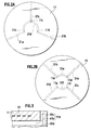
line 1A-1A, and a FIG. 1C is a side view when viewing FIG. 1A from a direction of an arrow C. - FIG. 2A and FIG. 2B are plan views showing gas providing passages and coupling passages of a processing device according to the embodiment of the present invention.
- FIG. 3 is a partial cross-sectional view of the processing device according to the embodiment of the present invention.
- FIG. 4 shows results of Example.
- A processing device shown in FIG. 1A to FIG. 1C is one of processing devices which hold a processing target and perform a variety of processing for the processing target. The
processing device 1 performs heating processing for the processing target. For example, the processing target includes asubstrate 2 such as a semiconductor substrate and a liquid crystal substrate. Theheating device 1 has asubstrate mounting surface 1a, and thesubstrate 2 is mounted on thesubstrate mounting surface 1a. Then, theheating device 1 heats thesubstrate 2 on thesubstrate mounting surface 1a. - The
heating device 1 includes abase 11, aresistance heating body 12, atubular member 13,power supply members 14, andinsulating pipes 15. Thebase 11 has thesubstrate mounting surface 1a, and holds thesubstrate 2 as the processing target. On thesubstrate mounting surface 1a, a concave portion (a pocket) for mounting thesubstrate 2 thereon, a plurality of convex portions (embosses), grooves, and the like, which support thesubstrate 2, may be formed. A shape of thebase 11 is not limited. For example, thebase 11 can be formed into a disc-like or polygonal plate shape. It is preferable that a thickness of thebase 11 be 30 mm or less. According to this, thermal conductivity of thebase 11 can be enhanced, and uniform heating performance of thesubstrate mounting surface 1a can be enhanced. - In the
base 11,gas providing passages 11a which provide gas to an outer circumference of thebase 11 are formed. Eachgas providing passage 11a is provided to thetubular member 13 and provides the gas A introduced from thetubular member 13 to the outer circumference of thebase 11. Then, the gas A is emitted from emission holes formed on the outer circumferential surface of thebase 11 . For example, as shown in FIG. 1A, thegas providing passage 11a can provide the gas A from the inside of thebase 11 toward the outer circumference of thebase 11. For example, thegas providing passage 11a can provide atmospheric gas which stabilizes a process in thesubstrate 2, reaction gas, and the like. For example, thegas providing passage 11a can provide nitrogen gas, argon gas, helium gas, and the like as the atmospheric gas. - The
gas providing passage 11a has a circular cross-sectional shape, thus making it easy to generate a laminar flow in thegas providing passage 11a, and making it possible to stabilize the flow of the gas. Hence, theheating device 1 can stably provide the gas to the outer circumference of thebase 11. For example, the flow of the gas in thegas providing passage 11a can be stabilized, and a loss of such a gas flow can be reduced. Hence, theheating device 1 can stably provide the gas at a desired flow rate. - It is preferable that the
gas providing passage 11a be formed at a position closer to aback surface 1b of thebase 11 than to theresistance heating body 12, that is, below theresistance heating body 12 in FIG. 1A. In the conventional heating device, the gas providing passage has been formed above the resistance heating body. Accordingly, a temperature distribution of thesubstrate mounting surface 1a has been changed by heat communication of the gas flowing in the gas providing passage, and it has been difficult to ensure the uniform heating performance of thesubstrate mounting surface 1a. As opposed to this, thegas providing passage 11a is formed below theresistance heating body 12, thus making it possible to prevent thegas providing passage 11a from affecting heat conduction from theresistance heating body 12. Hence, an influence given by thegas providing passage 11a to the temperature distribution of thesubstrate mounting surface 1a can be reduced, and the uniform heating performance of thesubstrate mounting surface 1a can be enhanced. - Moreover, it is preferable that each
gas providing passage 11a be formed by machining. According to this, deformation of thegas providing passage 11a can be prevented, and the flow of the gas in thegas providing passage 11a can be stabilized more. Hence, theheating device 1 can provide the gas more stably. For example, theheating device 1 can provide the gas at the desired flow rate more stably. - Each
gas providing passage 11a is formed to reach the outer circumference of the base 11 so as to be capable of providing the gas to the outer circumference of thebase 11. For example, thegas providing passage 11a is formed from the center of the base 11 in the diameter direction toward the outside thereof in the diameter direction. Although thegas providing passage 11a may have a bent portion, it is preferable that thegas providing passage 11a be linear. According to this, the flow of the gas can be stabilized more stably, and the loss of the gas flow can be reduced more. - It is preferable that a diameter (inner diameter) of each
gas providing passage 11a be 0.5 to 20 mm. According to this, the flow of the gas in thegas providing passage 11a can be stabilized more. Moreover, it is preferable that a length of thegas providing passage 11a be 50 to 300 mm. As described above, thegas providing passage 11a is formed into a cylindrical shape, and accordingly, the loss of the gas flow can be reduced more. - In the
base 11, thegas providing passages 11a andcoupling passages 11b are formed. Eachcoupling passage 11b couples thegas providing passage 11a and agas introduction passage 13a which is formed in thetubular member 13 and introduces the gas into thegas providing passage 11a to each other. Specifically, on theback surface 1b of thebase 11, which is an opposite surface to thesubstrate mounting surface 1a, through holes serving as thecoupling passages 11b, through which both of thegas providing passages 11a and thegas introduction passages 13a are connected to each other, are formed. Eachcoupling passage 11b couples thegas providing passage 11a and thegas introduction passage 13a to each other, and introduces, to thegas providing passage 11a, the gas A provided from thegas introduction passage 13a. - Moreover, the plurality of
gas providing passages 11a can be formed. In such a way, the gas of which flow rate is adjusted can be provided from eachgas proving passage 11a. For example, such an adjustment can be performed so that the flow rates of the gas from all thegas providing passages 11a can be substantially the same. According to this, theheating device 1 can provide a substantially uniform amount of the gas from the plurality ofgas providing passages 11a. Alternatively, an adjustment can be performed so that the gas flow rate of onegas providing passage 11a which provides the gas to a portion among the outer circumference of thebase 11, to which the gas is desired to be provided concentratedly, can be made larger than those of the othergas providing passages 11a. According to this, theheating device 1 can provide the gas while increasing the flow rate thereof for the target portion more than those for the other portions. For example, a diameter, length, surface roughness, and the like of eachgas providing passage 11 are adjusted, thus making it possible to adjust the gas flow rate from eachgas providing passage 11a. - In the case of forming the plurality of
gas providing passages 11a, for example, as shown in FIG. 1B, twogas providing passages 11a can be formed at an interval of 180° along the circumference direction of thebase 11. Moreover, as shown in FIG. 2A, threegas providing passages 21a to 21c can be formed at an interval of 120°. Furthermore, as shown in FIG. 2B, fourgas providing passages 31a to 31d can be formed at an interval of 90°. The number of gas providing passages is not limited, and as a matter of course, five or more gas providing passages may be formed. Moreover, the interval among the gas providing passages is not limited to such equal intervals, and may be different intervals. - As described above, in the case of forming the plurality of gas providing passages, the coupling passage which couples the plurality of gas providing passages to one another can be formed in the
base 11. According to this, the gas can be distributed to the respective gas providing passages. Hence, theheating device 1 can stably provide the gas at the desired flow rate from the respective gas providing passages. - For example, as shown in FIG. 2A, a
coupling passage 21d which couples the plurality ofgas providing passages 21a to 21c to one another can be formed. Moreover, the plurality of coupling passages can also be formed. For example, as shown in FIG. 2B, acoupling passage 31e which couples thegas providing passage 31a and thegas providing passage 31b to each other, and acoupling passage 31f which couples thegas providing passage 31c and thegas providing passage 31d to each other, can be formed. - For example, the
coupling passages base 11. For example, grooves and the like can be formed as thecoupling passages - For example, as shown in FIG. 2A, the
coupling passage 21d can be formed at a position of being connected to thecoupling passages 11b . In such a way, the gas can be introduced into thegas providing passages coupling passages 11b. Moreover, acoupling passage 11c which connects thecoupling passage 21d and agas providing passage 21c which is not connected to thecoupling passage 11b to each other can be formed on the back surface of thebase 11. As thecoupling passage 11c, for example, a through hole connected to both of thegas providing passage 21c and thecoupling passage 21d can be formed. In such a way, the gas can also be introduced to thegas providing passage 21c which is not connected to thecoupling passage 11b. For example, as thecoupling passage 21d as described above, a circular arc groove which connects thecoupling passage 11b and thecoupling passage 11c to each other can be formed. As the coupling passage, a linear groove may also be formed. By forming thecoupling passage 21d into the circular arc groove, the lengths of the respective gas providing passages can be uniformed, and this is preferable. - Alternatively, as shown in FIG. 2B, a
coupling passage 11d which connects thegas providing passage 31a and thegas providing passage 31e to each other, and acoupling passage 11e which connects thegas providing passage 31b and thecoupling passage 31e to each other, can be formed on the back surface of thebase 11. For example, as thecoupling passage 11d, a though hole connected to both of thegas providing passage 31a and thecoupling passage 31e can be formed. As thecoupling passage 11e, a through hole connected to both of thegas providing passage 31b and thecoupling passage 31e can be formed. As thecoupling passage 31e, for example, a circular arc groove which connects thecoupling passage 11d and thecoupling passage 11e to each other can be formed. In this case, thecoupling passage 31e is connected to thegas introduction passages 13a of thetubular member 13, and also functions as a coupling passage which couples thegas providing passages gas introduction passages 13a to each other. - In a similar way, a
coupling passage 11f which connects thegas providing passage 31c and thecoupling passage 31f to each other, and acoupling passage 11g which connects thegas providing passage 31d and thecoupling passage 31f to each other, can be formed on the back surface of thebase 11. For example, as thecoupling passage 11f, a through hole connected to both of thegas providing passage 31c and thecoupling passage 31f can be formed. As thecoupling passage 11g, a through hole connected to both of thegas providing passage 31d and thecoupling passage 31f can be formed. As thecoupling passage 31f, for example, a circular arc groove which connects thecoupling passage 11f and thecoupling passage 11g to each other can be formed. In this case, thecoupling passage 31f is connected to thegas introduction passage 13a of thetubular member 13, and also functions as a coupling passage which couples thegas providing passages gas introduction passages 13a to each other. - It is preferable to also form the
coupling passages coupling passages - It is preferable that the base 11 be formed of ceramics. For example, the
base 11 can contain aluminum nitride (A1N), silicon nitride (Si3N4), silicon carbide (SiC), alumina (Al2O3), sialon (SiAlON), and the like. According to this, theheating device 1 excellent in corrosion resistance and heat resistance can be provided. It is more preferable that the base 11 contain the aluminum nitride. According to this, the uniform heating performance of thesubstrate mounting surface 1a can be enhanced. - The
resistance heating body 12 is formed in thebase 11. It is preferable that theresistance heating body 12 be embedded in thebase 11. Theresistance heating body 12 generates heat upon receiving a supply of electric power, and raises temperature of thesubstrate heating surface 1a. For example, theresistance heating body 12 can be formed of a high melting point material. For example, theresistance heating body 12 can be formed of tungsten, molybdenum, a tungsten-molybdenum alloy, tungsten carbide, molybdenum carbide, or the like. A form of theresistance heating body 12 is not limited, and for example, one formed by printing a printing paste containing high melting point material powder, a linear, coil-like, belt-like bulk body or sheet (foil) of the high melting point material, a thin film of the high melting point material, which is formed by CVD or PVD, and the like, can be used. Moreover, a shape of theresistance heating body 12 is not limited, either, and theresistance heating body 12 can be formed into a spiral shape, a mesh (wire netting) shape, a punched shape (punching metal), a shape having plural folded portions, and the like. - As shown in FIG. 1A, the
tubular members 13 support thebase 11. Moreover, eachtubular member 13 introduces the gas into thegas providing passage 11a of thebase 11. Specifically, thetubular member 13 has thegas introduction passage 13a which introduces the gas into thegas providing passage 11a. Thegas introduction passage 13a communicates with thecoupling passage 11b of thebase 11, and introduces the gas A into thegas providing passage 11a through thecoupling passage 11b. Note that, in the case of forming thegas providing passages 31a to 31d shown in FIG. 2B, thegas introduction passages 13a are connected to thecoupling passages base 11. For example, eachgas introduction passage 13a can be made as a through hole which penetrates from a lower end of thetubular member 13 to an upper end thereof. It is preferable that a diameter of eachgas introduction passage 13a be 2 to 10 mm. Moreover, on an inner circumference side of thetubular member 13, thepower supply members 14 and the insulatingpipes 15 are arranged. - Each
tubular member 13 is bonded to the back surface of thebase 11. For example, thetubular member 13 can be bonded to thebase 11 by a solid-phase bonding method, a liquid-phase bonding method, and the like, which use a binder. In this case, thebase 11 and thetubular member 13 can be integrated together, and air tightness of thegas introduction passage 13a of thetubular member 13 and thegas providing passage 11a of the base 11 can be ensured. Alternatively, thetubular member 13 can also be bonded to thebase 11 by a sealing member such as an O-ring and a metal packing. Also in such a way, the air tightness of thegas introduction passage 13a of thetubular member 13 and thegas providing passage 11a of the base 11 can be ensured. Note that the bonding method of thebase 11 and thetubular member 13 is not limited to these, and various bonding methods capable of ensuring the air tightness of thegas introduction passage 13a of thetubular member 13 and thegas providing passage 11a of the base 11 can be used. - In a similar way to the
base 11, thetubular member 13 can be formed of the ceramics. It is preferable that thetubular member 13 be formed of the ceramics of the same type as that of thebase 11. - The
power supply members 14 are electrically connected to theresistance heating body 12, and supplies the electric power to theresistance heating body 12. Thepower supply members 14 can be connected to theresistance heating body 12 by brazing, welding, eutectic bonding, crimping, fitting, screwing, and the like. For eachpower supply member 14, a power supply rod, a power supply line (a power supply wire), a complex of the power supply rod and the power supply line, and the like, can be used. Preferably, thepower supply members 14 are formed of metal, more preferably, of nickel. Thepower supply members 14 are housed in the insulatingpipes 15. The insulatingpipes 15 are bonded to the back surface of thebase 11. - For example, the
heating device 1 can be fabricated in the following manner. Ceramic powder serving as a main component and sintering aids are mixed together, and ceramic raw material powder is prepared. To the ceramic raw material powder, a binder, water, a dispersant, and the like are added and mixed, and slurry is made. The slurry is granulated by a spray granulation method and the like, and granulated powder is made. By using the granulated powder, a ceramic molded body is fabricated by a die molding method, a CIP method, a slip cast method, or the like. The ceramic molded body is fired under firing conditions (a firing temperature, a firing atmosphere, a firing method, and the like) corresponding to the ceramic raw material powder, and a ceramic sintered body is fabricated. - The
resistance heating body 12 is formed on the ceramic sintered body. For example, theresistance heating body 12 can be formed by printing a printing paste containing the high melting point material powder on the ceramic sintered body by using a screen printing method or the like. Alternatively, theresistance heating body 12 can also be formed by mounting the bulk body or sheet (foil) of the high melting point material on the ceramic sintered body, and by forming the thin film of the high melting point material on the ceramic sintered body by the CVD or the PVD. - Next, the ceramic molded body is formed on the ceramic sintered body and the
resistance heating body 12. For example, the ceramic sintered body on which theresistance heating body 12 is formed is set in a metal mold or the like, and the granulated powder is filled onto the ceramic sintered body and theresistance heating body 12, thus making it possible to form the ceramic molded body. Alternatively, the ceramic molded body may be fabricated by using the granulated powder by the die molding method, the CIP method, the slip cast method, or the like, and the ceramic molded body may be mounted and pressed on the ceramic sintered body and theresistance heating body 12. - Then, the ceramic sintered body, the
resistance heating body 12, and the ceramic molded body are fired integrally according to the firing conditions corresponding to the ceramic raw material powder. In such a way, the base 11 in which theresistance heating body 12 is embedded can be fabricated. For example, the above-described bodies can be fired while being pressurized in one axial direction by using a hot press method or the like. - Note that a temporarily fired body of the ceramics may be fabricated in place of the ceramic sintered body, and that the
resistance heating body 12 may be formed on the temporarily fired body of the ceramics. Alternatively, a laminated body of the ceramic molded body, theresistance heating body 12, and the ceramic molded body may be fabricated, and the laminated body may be fired integrally by the hot press method or the like. - The
gas providing passages 11a are formed in the obtainedbase 11 by the machining. For example, thegas providing passages 11a are formed in the base 11 from the outside of the base 11 in the diameter direction toward the inside thereof in the diameter direction by a drilling processing using a machining center (MC) and the like. Moreover, holes for thecoupling passages 11b and holes for inserting thepower supply members 14 into the base 11 are formed therein by a process. - Separately from the
base 11, a ceramic molded body serving as thetubular member 13 is fabricated by using granulated powder prepared in a similar way thereto by the die molding method, the CIP method, the slip cast method, or the like. Then, the ceramic molded body is fired under the firing conditions corresponding to the ceramic raw material powder, and thetubular member 13 is fabricated. Thegas introduction passages 13a are formed by the machining in the obtainedtubular member 13. - Then, the
base 11 and thetubular member 13 are bonded to each other. At this time, thebase 11 and thetubular member 13 are bonded to each other so that thecoupling passages 11b and thegas introduction passages 13a can be fitted to each other. Thebase 11 and thetubular member 13 can be bonded to each other by the solid-phase bonding method and the liquid-phase bonding method, which use the binder, and seal bonding using the O-ring, the metal packing, and the like. Moreover, the insulatingpipes 15 are inserted into thetubular member 13, and thebase 11 and the insulatingpipes 15 are also bonded to each other in a similar way to the above. Finally, thepower supply members 14 are inserted into the insulatingpipes 15, and are electrically connected to theresistance heating body 12. - Note that the present invention is not limited to the above-described embodiment, and various alterations are possible therefor. For example, the gas providing passages just need to be formed to reach the outer circumference of the base 11 so as to be capable of providing the gas to the outer circumference of the
base 11. For example, as shown in FIG. 3,gas providing passages 41a may also be formed from the inside of the outer circumference of the base 11 toward the above. - Specifically, each
gas providing passage 41a is formed into a substantially L shape in cross section, which has apassage 41b extended from the inside of the base 11 in the diameter direction toward the outside thereof in the diameter direction, and apassage 41c extended from the inside of the outer circumference of the base 11 toward the above. - For example, the
gas providing passages 41a as described above can be formed in the following manner. First, as shown in FIG. 3, thepassages 41b (lateral holes) are formed by the machining from a side surface of the base 11 toward the inside thereof in the diameter direction. Next, from an upper surface of the base 11 in the vicinity of the outer circumference of thebase 11, thepassages 41c (longitudinal holes) connected to thepassages 41b are formed by the machining. Then, ends of thepassages 41b (lateral holes) on the side surface of the base 11 are closed by sealingmembers 41d. Specifically, the sealingmembers 41d which are formed of the ceramics and are fitted into holes formed on the side surface of the base 11 are fixed by brazing, crimping, screwing, and the like. - Alternatively, the
resistance heating body 12 may be provided on the surface of thebase 11 without being embedded in the inside of thebase 11. Moreover, theheating device 1 can include an electrostatic electrode which generates electrostatic absorption force, or a high-frequency electrode which excites the reaction gas. Specifically, the electrostatic electrode or the high-frequency electrode can be embedded in thebase 11. Moreover, as a processing device, a plasma processing device which performs plasma processing for thesubstrate 2, a sputtering processing device which performs sputtering processing therefor, and the like, can be used besides theheating device 1. - Next, the present invention will be specifically described through an example.
- 95 wt% aluminum nitride powder and 5 wt% yttrium oxide powder (sintering aids) were mixed together, and the ceramic raw material powder was prepared. The binder (PVA), the water, and the dispersant were added to the ceramic raw material powder, and were mixed together by using a ball mill, and the slurry was thus made. The slurry was sprayed and dried by using a spray dryer, and the granulated powder was made. By using the granulated powder, an aluminum nitride molded body was fabricated by the die molding method. The aluminum nitride molded body was fired at 1900°C in a nitrogen gas atmosphere by using the hot press method, and an aluminum nitride sintered body was fabricated.
- Next, ethyl cellulose was mixed as the binder into mixed powder of 80 wt% tungsten carbide and 20 wt% aluminum nitride powder, and the printing paste was prepared. The
resistance heating body 12 was formed on the aluminum nitride sintered body by the screen printing method, followed by drying. - Next, the aluminum nitride sintered body on which the
resistance heating body 12 was formed was set in a metal mold, and the granulated powder was filled onto the aluminum nitride sintered body and theresistance heating body 12, followed by pressurization, and an aluminum nitride molded body was fabricated. Then, the aluminum nitride sintered body, theresistance heating body 12, and the aluminum nitride molded body were set in a carbon-made sheath, and were fired at 1900°C in the nitrogen gas atmosphere by the hot press method. - In such a way, the
base 11 of the aluminum nitride sintered body with a diameter of 330 mm and a thickness of 25 mm was fabricated. Thegas providing passages 31a to 31d and thecoupling passages base 11 by machining using a machining center (MC). Specifically, fourgas providing passages 31a to 31d were formed by the process from the side surface of the base 11 toward the inside thereof in the diameter direction at an interval of 90° along the circumference direction of thebase 11. Diameters (0) of the respectivegas providing passages 31a to 31d were set at 4mm, and lengths thereof were set at 135 mm. Moreover, two circulararc coupling passages base 11 . Widths of therespective coupling passages power supply members 14 into the base 11 were formed thereon by the process. - Moreover, a tubular aluminum nitride molded body was fabricated by the CIP method using granulated powder similar to the above. Then, the tubular aluminum nitride molded body was fired at 1900°C in the nitrogen gas atmosphere by a normal pressure firing method. In such a way, the
tubular member 13 of the aluminum nitride sintered body with a diameter of 30 mm and a length of 250 mm was fabricated. As thegas introduction passages 13a, two through holes with a diameter (0) of 5 mm were formed in thetubular member 13 by machining using a machining center (MC). - The
base 11 and thetubular member 13 were bonded to each other so that centers of thecoupling passages base 11 and thegas introduction passages 13a of thetubular member 13 could be fitted to each other. In such a way, thegas introduction passages 13a and thegas providing passages 31a to 31d were connected to each other through thecoupling passages base 11 and an end surface of thetubular member 13, and thebase 11 and thetubular member 13 were subjected to a heat treatment at 1850°C, and thus were bonded to each other by the solid-phase bonding method. In a similar way to the above, thebase 11 and the insulatingpipes 15 were also bonded to each other. Finally, the power supply rods made of nickel were inserted as thepower supply members 14 into the insulatingpipes 15, and were bonded to theresistance heating member 12 by the brazing. Aheating device 1 according to the Example of the Present Invention was fabricated in the above-described manner. - The nitrogen gas was provided as atmospheric gas at 20 sccm (standard cc/min) to the respective
gas introduction passages 13a of thetubular member 13 of the obtainedheating device 1. Then, flow rates of the gas provided from the respectivegas providing passages 31a to 31d of the base 11 to the outer circumference of the base 11 were measured by using a flowmeter. - The flow rate of the gas from the
gas providing passages 13a was 9.7 sccm, the flow rate of the gas from thegas providing passage 31b was 9.2 sccm, the flow rate of the gas from thegas providing passage 31c was 9.3 sccm, and the flow rate of the gas from thegas providing passage 31d was 9.6 sccm. Variations of the flow rates of the gas from the respectivegas providing passages 31a to 31d were suppressed to be as extremely small as 1 sccm or less, and the atmospheric gas was able to be stably provided to the outer circumference of thebase 11. - Subsequently, a heating device according to a Comparative Example was fabricated. Basically, the heating device according to the comparative example was fabricated of materials by a procedure, both of which were similar to those of the heating device according to the Example of the Present Invention. However, gas providing passages in a base were formed by coupling two plate materials, one of which has grooves on a surface thereof, to each other. Specifically, two disc-like plates were fabricated, rectangular grooves were extended along the diameter direction on a surface of one of the plates, and the plate having the rectangular grooves formed thereon and the other plate of which surface was formed into a planar shape were coupled to each other. In such a way, the gas providing passages each having a rectangular shape in cross section with a width of 6 mm and a height of 2 mm were formed. Note that a diameter and thickness of the base and a length, number, and arrangement of the gas providing passages were set similar to those of the Example of the Present Invention.
- The nitrogen gas was provided as atmospheric gas at 20 sccm (standard cc/min) to the respective gas introduction passages of a tubular member of the heating device thus obtained. Then, flow rates of the gas provided from the respective gas providing passages of the base to an outer circumference of the base were measured by using a flowmeter.
- As shown in FIG. 4, the flow rates of the gas from the gas providing passages were 7.3 sccm, 8.3 sccm, 6.8 sccm, and 9. 4 sccm. As described above, variation of the flow rates of the gas according to the Comparative Example was 2.6 sccm, which was double or more the variation according to the Example of the Present Invention.
- Note that, in addition to the variation of the flow rates of the gas, which was described above, variation of uniform heating performance on a surface of the base was also verified. The members to be heated were housed in a vacuum atmosphere, and differences among surface temperatures of plural spots of each thereof when an average value of the temperatures on the surface of the base of each member to be heated reached 500°C were measured by using an infrared radiometer. As shown in FIG. 4, a difference between the maximum value and the minimum value in the temperature on the surface of the base according to the example of the present invention was 5.3°C, and a difference between the maximum value and the minimum value in the temperature on the surface of the base according to the comparative example was 12.3°C. As described above, the temperature difference in the example of the present invention became half or less of the temperature difference in the comparative example, and it was found that the example of the present invention was more excellent in uniform heating performance.
- Moreover, in the case of the Comparative Example, a temperature of the surface of the base, which corresponded to the portions where the gas providing passages were formed, became lower than a temperature of the other portions. However, in the case of the Example of the Present Invention, such temperature lowering did not occur.
Claims (7)
- A processing device, comprising:a base (11) which holds a processing target (2),wherein a gas providing passage (11a, 21a, 21b, 31a, 31b, 31c, 31d, 41a) circular in cross section is formed in the base, the gas providing passage providing gas to an outer circumference of the base.
- The processing device according to claim 1, further comprising a resistance heating body (12) in the base (11).
- The processing device according to claim 2, wherein the gas providing passage (11a, 21a, 21b, 31a, 31b, 31c, 31d, 41a) is formed closer to a back surface of the base than to the resistance heating body.
- The processing device according to any one of claims 1 to 3, further comprising a tubular member (13) bonded to the base (11), the tubular member including a gas introduction passage (13a) which introduces the gas into the gas providing passage (11a, 21a, 21b, 31a, 31b, 31c, 31d, 41a),
wherein a coupling passage (11b, 11c, 11d, 11e, 11f, 11g, 21d, 31e, 31f) which allows the gas providing passage and the gas introduction passage to communicate with each other is formed in the base. - The processing device according to any one of claims 1 to 4, wherein a plurality of the gas providing passages (11a, 21a, 21b, 31a, 31b, 31c, 31d, 41a) are provided.
- The processing device according to claim 5, wherein the coupling passage (11b, 11c, 11d, 11e, 11f, 11g, 21d, 31e, 31f) which couples the plurality of gas providing passages (11a, 21a, 21b, 31a, 31b, 31c, 31d, 41a) to one another is formed in the base (11),.
- The processing device according to any one of claims 1 to 6, wherein the gas providing passage (11a, 21a, 21b, 31a, 31b, 31c, 31d, 41a) is formed by machining.
Applications Claiming Priority (1)
| Application Number | Priority Date | Filing Date | Title |
|---|---|---|---|
| US66220705P | 2005-03-16 | 2005-03-16 |
Publications (3)
| Publication Number | Publication Date |
|---|---|
| EP1703546A2 true EP1703546A2 (en) | 2006-09-20 |
| EP1703546A3 EP1703546A3 (en) | 2008-09-03 |
| EP1703546B1 EP1703546B1 (en) | 2017-03-22 |
Family
ID=36190768
Family Applications (1)
| Application Number | Title | Priority Date | Filing Date |
|---|---|---|---|
| EP06251414.6A Ceased EP1703546B1 (en) | 2005-03-16 | 2006-03-16 | Processing device |
Country Status (5)
| Country | Link |
|---|---|
| US (1) | US8394199B2 (en) |
| EP (1) | EP1703546B1 (en) |
| JP (1) | JP4590364B2 (en) |
| KR (1) | KR100784216B1 (en) |
| TW (1) | TWI297908B (en) |
Families Citing this family (14)
| Publication number | Priority date | Publication date | Assignee | Title |
|---|---|---|---|---|
| KR100867191B1 (en) * | 2006-11-02 | 2008-11-06 | 주식회사 유진테크 | Substrate Processing Apparatus and Substrate Processing Method |
| US20100297347A1 (en) * | 2009-04-24 | 2010-11-25 | Applied Materials, Inc. | Substrate support having side gas outlets and methods |
| JP5401230B2 (en) * | 2009-09-17 | 2014-01-29 | 株式会社ニューフレアテクノロジー | Film forming apparatus and film forming method |
| US9633889B2 (en) * | 2013-03-06 | 2017-04-25 | Applied Materials, Inc. | Substrate support with integrated vacuum and edge purge conduits |
| US9738975B2 (en) | 2015-05-12 | 2017-08-22 | Lam Research Corporation | Substrate pedestal module including backside gas delivery tube and method of making |
| US10157755B2 (en) * | 2015-10-01 | 2018-12-18 | Lam Research Corporation | Purge and pumping structures arranged beneath substrate plane to reduce defects |
| JP6911140B2 (en) * | 2017-11-02 | 2021-07-28 | 日本碍子株式会社 | Semiconductor manufacturing equipment members, their manufacturing methods and molding dies |
| DE102018105220A1 (en) * | 2018-03-07 | 2019-09-12 | Hauni Maschinenbau Gmbh | Method for producing an electrically operable radiator for an inhaler |
| CN111448647B (en) * | 2018-03-26 | 2023-08-01 | 日本碍子株式会社 | Electrostatic Chuck Heater |
| US11521884B2 (en) * | 2018-06-29 | 2022-12-06 | Taiwan Semiconductor Manufacturing Co., Ltd. | Electrostatic chuck sidewall gas curtain |
| JP6959201B2 (en) * | 2018-08-29 | 2021-11-02 | 日本碍子株式会社 | Ceramic heater |
| JP6873178B2 (en) * | 2019-03-26 | 2021-05-19 | 日本碍子株式会社 | Semiconductor manufacturing equipment members, their manufacturing methods and molding dies |
| KR102752083B1 (en) * | 2023-10-06 | 2025-01-10 | 주식회사 미코세라믹스 | Ceramic susceptor |
| KR102752082B1 (en) | 2023-12-12 | 2025-01-10 | 주식회사 미코세라믹스 | Susceptor including purge gas flow passage |
Family Cites Families (25)
| Publication number | Priority date | Publication date | Assignee | Title |
|---|---|---|---|---|
| EP0448346B1 (en) * | 1990-03-19 | 1997-07-09 | Kabushiki Kaisha Toshiba | Vapor-phase deposition apparatus |
| US5800618A (en) * | 1992-11-12 | 1998-09-01 | Ngk Insulators, Ltd. | Plasma-generating electrode device, an electrode-embedded article, and a method of manufacturing thereof |
| JPH06151332A (en) | 1992-11-12 | 1994-05-31 | Ngk Insulators Ltd | Ceramic heater |
| US5343938A (en) * | 1992-12-24 | 1994-09-06 | Vlsi Technology, Inc. | Method and apparatus for thermally insulating a wafer support |
| DE69427722T2 (en) * | 1993-05-21 | 2002-05-08 | Kabushiki Kaisha Toshiba, Kawasaki | Sintered body made of aluminum nitriol and process for its production |
| JPH07172921A (en) | 1993-12-20 | 1995-07-11 | Toshiba Corp | Aluminum nitride sintered body and manufacturing method thereof |
| US5888304A (en) * | 1996-04-02 | 1999-03-30 | Applied Materials, Inc. | Heater with shadow ring and purge above wafer surface |
| US5551983A (en) * | 1994-11-01 | 1996-09-03 | Celestech, Inc. | Method and apparatus for depositing a substance with temperature control |
| JP3599204B2 (en) * | 1995-06-08 | 2004-12-08 | アネルバ株式会社 | CVD equipment |
| JP3457477B2 (en) * | 1995-09-06 | 2003-10-20 | 日本碍子株式会社 | Electrostatic chuck |
| EP0764979A3 (en) * | 1995-09-20 | 1998-07-15 | Hitachi, Ltd. | Electrostatically attracting electrode and a method of manufacture thereof |
| JPH09256153A (en) * | 1996-03-15 | 1997-09-30 | Anelva Corp | Substrate processing equipment |
| US5748435A (en) * | 1996-12-30 | 1998-05-05 | Applied Materials, Inc. | Apparatus for controlling backside gas pressure beneath a semiconductor wafer |
| JP2001522142A (en) * | 1997-11-03 | 2001-11-13 | エーエスエム アメリカ インコーポレイテッド | Improved low mass wafer support system |
| US6126382A (en) * | 1997-11-26 | 2000-10-03 | Novellus Systems, Inc. | Apparatus for aligning substrate to chuck in processing chamber |
| US6179924B1 (en) | 1998-04-28 | 2001-01-30 | Applied Materials, Inc. | Heater for use in substrate processing apparatus to deposit tungsten |
| US6280584B1 (en) * | 1998-07-29 | 2001-08-28 | Applied Materials, Inc. | Compliant bond structure for joining ceramic to metal |
| US6223447B1 (en) * | 2000-02-15 | 2001-05-01 | Applied Materials, Inc. | Fastening device for a purge ring |
| US6494955B1 (en) * | 2000-02-15 | 2002-12-17 | Applied Materials, Inc. | Ceramic substrate support |
| US6960743B2 (en) * | 2000-12-05 | 2005-11-01 | Ibiden Co., Ltd. | Ceramic substrate for semiconductor manufacturing, and method of manufacturing the ceramic substrate |
| TWI272689B (en) * | 2001-02-16 | 2007-02-01 | Tokyo Electron Ltd | Method and apparatus for transferring heat from a substrate to a chuck |
| US6702900B2 (en) * | 2001-03-22 | 2004-03-09 | Taiwan Semiconductor Manufacturing Co., Ltd. | Wafer chuck for producing an inert gas blanket and method for using |
| JP4386606B2 (en) * | 2001-11-08 | 2009-12-16 | 日本碍子株式会社 | Method for manufacturing support device |
| US6730175B2 (en) * | 2002-01-22 | 2004-05-04 | Applied Materials, Inc. | Ceramic substrate support |
| EP1588404A2 (en) * | 2003-01-17 | 2005-10-26 | General Electric Company | Wafer handling apparatus |
-
2006
- 2006-03-14 JP JP2006069156A patent/JP4590364B2/en not_active Expired - Lifetime
- 2006-03-14 TW TW095108551A patent/TWI297908B/en active
- 2006-03-15 KR KR1020060023953A patent/KR100784216B1/en not_active Expired - Lifetime
- 2006-03-15 US US11/375,815 patent/US8394199B2/en active Active
- 2006-03-16 EP EP06251414.6A patent/EP1703546B1/en not_active Ceased
Also Published As
| Publication number | Publication date |
|---|---|
| TW200705514A (en) | 2007-02-01 |
| EP1703546A3 (en) | 2008-09-03 |
| EP1703546B1 (en) | 2017-03-22 |
| US20060219176A1 (en) | 2006-10-05 |
| US8394199B2 (en) | 2013-03-12 |
| TWI297908B (en) | 2008-06-11 |
| JP4590364B2 (en) | 2010-12-01 |
| KR20060100262A (en) | 2006-09-20 |
| JP2006261670A (en) | 2006-09-28 |
| KR100784216B1 (en) | 2007-12-11 |
Similar Documents
| Publication | Publication Date | Title |
|---|---|---|
| US8394199B2 (en) | Processing device | |
| US7189946B2 (en) | Substrate heating device | |
| JP7149914B2 (en) | Components for semiconductor manufacturing equipment | |
| JP4467453B2 (en) | Ceramic member and manufacturing method thereof | |
| EP1703545B1 (en) | Gas providing member and processing device | |
| EP1672679B1 (en) | Alumina member and manufacturing method thereof | |
| US7544916B2 (en) | Heating device | |
| KR100438881B1 (en) | Wafer holder for semiconductor manufacturing apparatus and semiconductor manufacturing apparatus using the same | |
| JP4648030B2 (en) | Yttria sintered body, ceramic member, and method for producing yttria sintered body | |
| CN1917722B (en) | heating equipment | |
| KR20030007929A (en) | Ceramic bonded body and its producing method, and ceramic structure for semiconductor wafer | |
| US20050082274A1 (en) | Substrate heater and fabrication method for the same | |
| JP2005018992A (en) | Electrode embedding member for plasma generator | |
| JP5062959B2 (en) | Ceramic member and manufacturing method thereof | |
| JP2001342079A (en) | Ceramic junction body | |
| KR100835629B1 (en) | Heating device | |
| KR100802376B1 (en) | Heating device | |
| JP2003151727A (en) | Planar ceramic heater | |
| JP2005116914A (en) | Electrode embedding member for plasma generator | |
| JPH10326671A (en) | Ceramic heater |
Legal Events
| Date | Code | Title | Description |
|---|---|---|---|
| PUAI | Public reference made under article 153(3) epc to a published international application that has entered the european phase |
Free format text: ORIGINAL CODE: 0009012 |
|
| AK | Designated contracting states |
Kind code of ref document: A2 Designated state(s): AT BE BG CH CY CZ DE DK EE ES FI FR GB GR HU IE IS IT LI LT LU LV MC NL PL PT RO SE SI SK TR |
|
| AX | Request for extension of the european patent |
Extension state: AL BA HR MK YU |
|
| PUAL | Search report despatched |
Free format text: ORIGINAL CODE: 0009013 |
|
| RIC1 | Information provided on ipc code assigned before grant |
Ipc: H01L 21/00 20060101ALI20080714BHEP Ipc: H01L 21/687 20060101ALI20080714BHEP Ipc: H01L 21/683 20060101ALI20080714BHEP Ipc: C23C 16/455 20060101AFI20080714BHEP Ipc: H05B 3/14 20060101ALI20080714BHEP |
|
| AK | Designated contracting states |
Kind code of ref document: A3 Designated state(s): AT BE BG CH CY CZ DE DK EE ES FI FR GB GR HU IE IS IT LI LT LU LV MC NL PL PT RO SE SI SK TR |
|
| AX | Request for extension of the european patent |
Extension state: AL BA HR MK YU |
|
| 17P | Request for examination filed |
Effective date: 20090302 |
|
| AKX | Designation fees paid |
Designated state(s): DE FR GB |
|
| 17Q | First examination report despatched |
Effective date: 20111213 |
|
| REG | Reference to a national code |
Ref country code: DE Ref legal event code: R079 Ref document number: 602006052029 Country of ref document: DE Free format text: PREVIOUS MAIN CLASS: H01L0021000000 Ipc: H01L0021670000 |
|
| GRAP | Despatch of communication of intention to grant a patent |
Free format text: ORIGINAL CODE: EPIDOSNIGR1 |
|
| RIC1 | Information provided on ipc code assigned before grant |
Ipc: H05B 3/14 20060101ALI20161014BHEP Ipc: H01L 21/687 20060101ALI20161014BHEP Ipc: H01L 21/67 20060101AFI20161014BHEP |
|
| INTG | Intention to grant announced |
Effective date: 20161111 |
|
| RIN1 | Information on inventor provided before grant (corrected) |
Inventor name: TOMITA, YASUMITSU Inventor name: UNNO, YUTAKA |
|
| GRAS | Grant fee paid |
Free format text: ORIGINAL CODE: EPIDOSNIGR3 |
|
| GRAA | (expected) grant |
Free format text: ORIGINAL CODE: 0009210 |
|
| AK | Designated contracting states |
Kind code of ref document: B1 Designated state(s): DE FR GB |
|
| REG | Reference to a national code |
Ref country code: GB Ref legal event code: FG4D |
|
| REG | Reference to a national code |
Ref country code: DE Ref legal event code: R096 Ref document number: 602006052029 Country of ref document: DE |
|
| REG | Reference to a national code |
Ref country code: DE Ref legal event code: R097 Ref document number: 602006052029 Country of ref document: DE |
|
| PLBE | No opposition filed within time limit |
Free format text: ORIGINAL CODE: 0009261 |
|
| STAA | Information on the status of an ep patent application or granted ep patent |
Free format text: STATUS: NO OPPOSITION FILED WITHIN TIME LIMIT |
|
| REG | Reference to a national code |
Ref country code: FR Ref legal event code: PLFP Year of fee payment: 13 |
|
| 26N | No opposition filed |
Effective date: 20180102 |
|
| PGFP | Annual fee paid to national office [announced via postgrant information from national office to epo] |
Ref country code: GB Payment date: 20220127 Year of fee payment: 17 Ref country code: DE Payment date: 20220203 Year of fee payment: 17 |
|
| PGFP | Annual fee paid to national office [announced via postgrant information from national office to epo] |
Ref country code: FR Payment date: 20220209 Year of fee payment: 17 |
|
| REG | Reference to a national code |
Ref country code: DE Ref legal event code: R119 Ref document number: 602006052029 Country of ref document: DE |
|
| GBPC | Gb: european patent ceased through non-payment of renewal fee |
Effective date: 20230316 |
|
| PG25 | Lapsed in a contracting state [announced via postgrant information from national office to epo] |
Ref country code: GB Free format text: LAPSE BECAUSE OF NON-PAYMENT OF DUE FEES Effective date: 20230316 |
|
| PG25 | Lapsed in a contracting state [announced via postgrant information from national office to epo] |
Ref country code: GB Free format text: LAPSE BECAUSE OF NON-PAYMENT OF DUE FEES Effective date: 20230316 Ref country code: FR Free format text: LAPSE BECAUSE OF NON-PAYMENT OF DUE FEES Effective date: 20230331 Ref country code: DE Free format text: LAPSE BECAUSE OF NON-PAYMENT OF DUE FEES Effective date: 20231003 |