EP1703269A1 - Apparatus for testing elastic material for leg garments - Google Patents
Apparatus for testing elastic material for leg garments Download PDFInfo
- Publication number
- EP1703269A1 EP1703269A1 EP06405095A EP06405095A EP1703269A1 EP 1703269 A1 EP1703269 A1 EP 1703269A1 EP 06405095 A EP06405095 A EP 06405095A EP 06405095 A EP06405095 A EP 06405095A EP 1703269 A1 EP1703269 A1 EP 1703269A1
- Authority
- EP
- European Patent Office
- Prior art keywords
- lever
- leg
- pressure sensors
- pressure
- bracket
- Prior art date
- Legal status (The legal status is an assumption and is not a legal conclusion. Google has not performed a legal analysis and makes no representation as to the accuracy of the status listed.)
- Withdrawn
Links
Images


Classifications
-
- G—PHYSICS
- G01—MEASURING; TESTING
- G01N—INVESTIGATING OR ANALYSING MATERIALS BY DETERMINING THEIR CHEMICAL OR PHYSICAL PROPERTIES
- G01N3/00—Investigating strength properties of solid materials by application of mechanical stress
- G01N3/08—Investigating strength properties of solid materials by application of mechanical stress by applying steady tensile or compressive forces
-
- D—TEXTILES; PAPER
- D06—TREATMENT OF TEXTILES OR THE LIKE; LAUNDERING; FLEXIBLE MATERIALS NOT OTHERWISE PROVIDED FOR
- D06H—MARKING, INSPECTING, SEAMING OR SEVERING TEXTILE MATERIALS
- D06H3/00—Inspecting textile materials
- D06H3/16—Inspecting hosiery or other tubular fabric; Inspecting in combination with turning inside-out, classifying, or other handling
-
- A—HUMAN NECESSITIES
- A61—MEDICAL OR VETERINARY SCIENCE; HYGIENE
- A61F—FILTERS IMPLANTABLE INTO BLOOD VESSELS; PROSTHESES; DEVICES PROVIDING PATENCY TO, OR PREVENTING COLLAPSING OF, TUBULAR STRUCTURES OF THE BODY, e.g. STENTS; ORTHOPAEDIC, NURSING OR CONTRACEPTIVE DEVICES; FOMENTATION; TREATMENT OR PROTECTION OF EYES OR EARS; BANDAGES, DRESSINGS OR ABSORBENT PADS; FIRST-AID KITS
- A61F13/00—Bandages or dressings; Absorbent pads
- A61F13/06—Bandages or dressings; Absorbent pads specially adapted for feet or legs; Corn-pads; Corn-rings
- A61F13/08—Elastic stockings; for contracting aneurisms
-
- G—PHYSICS
- G01—MEASURING; TESTING
- G01N—INVESTIGATING OR ANALYSING MATERIALS BY DETERMINING THEIR CHEMICAL OR PHYSICAL PROPERTIES
- G01N33/00—Investigating or analysing materials by specific methods not covered by groups G01N1/00 - G01N31/00
- G01N2033/0078—Investigating or analysing materials by specific methods not covered by groups G01N1/00 - G01N31/00 testing material properties on manufactured objects
- G01N2033/0086—Investigating or analysing materials by specific methods not covered by groups G01N1/00 - G01N31/00 testing material properties on manufactured objects clothes; hosiery
-
- G—PHYSICS
- G01—MEASURING; TESTING
- G01N—INVESTIGATING OR ANALYSING MATERIALS BY DETERMINING THEIR CHEMICAL OR PHYSICAL PROPERTIES
- G01N2203/00—Investigating strength properties of solid materials by application of mechanical stress
- G01N2203/02—Details not specific for a particular testing method
- G01N2203/026—Specifications of the specimen
- G01N2203/0262—Shape of the specimen
- G01N2203/0274—Tubular or ring-shaped specimens
Definitions
- the present invention relates to a device for testing elastic textile leg garments, in particular stockings or tights, medical compression stockings and support stockings.
- Elastic textile leg garments must be shaped so as to follow as closely as possible the contour of the leg of the person wearing the garment. For only in such a case can the legwear perform its function fully, without there being any points along the leg where the legwear either exerts too much or too little pressure.
- the circumference is also measured in the area of the buttocks and possibly also in the area of the waist. Based on these specifications, the legwear is then produced. According to this, however, it is also necessary to determine whether the specifications for the manufactured product have been complied with.
- the opposite longitudinal edges of the flattened stocking are attached to needles, which form two rows along the stocking length.
- These needles are movably mounted in such a way that the distance between two opposite Needles of the needle rows can be changed.
- the measurement as to whether the specifications have been met during the production of the stocking can, for example, be such that opposing needles are spaced apart from each other in accordance with the specification and that the tension in the stocking between two opposite needles is measured. So you can indeed determine whether the contour of the stocking has the course determined by the requirements. Because of the impingement on the needles the measured stocking is not for sale. Considering that such stockings are often custom-made, then the measurement of the finished stockings using the just mentioned device is ineffective.
- the object of the present device is to eliminate the mentioned as well as still further disadvantages of the prior art.
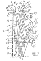
- Fig. 1 shows the model of a human leg, which can be used to demonstrate at which points or in which areas of the human body circumference measurements can be made in order to fit the leg pieces, e.g. to make medical stockings or tights.
- measurements are taken only above the foot.
- the circumference cH in the area of the buttocks and the circumference cT of the waist are also measured.
- the human legs differ from each other not only by the size of the circumference in said areas but also by the distances between these areas. These differences in distance are due to the different lengths of the legs. Therefore, these lengths are also determined during the measurements of a leg. These lengths are conveniently based on the underside of the foot, in particular on the underside of the heel.
- the area of the tether cB is located at a distance LB from the heel, etc., as indicated on the right in FIG.
- the present device for non-destructive testing of elastic Textile legwear is designed to allow adjustment of circumference values measured in the respective areas of a leg in the respective areas of the facility. Further, the present device allows to measure the amount of tension that prevail in those areas of the legwear corresponding to said areas of the leg. This guarantees that the finished product does not only exert its health-promoting effect, but that the legwear can also be worn comfortably.
- Fig. 2 shows in a side view one of the embodiments of the present device.
- 3 shows an enlarged detail from the upper area of FIG. 2.
- the present device is largely represented by a so-called kinematic scheme.
- This scheme also demonstrates, inter alia, the principle of the present device for a particular area of the leg. This principle can then be used repeatedly in a device of this type to test several areas of a legwear.
- the present device comprises a base plate 1 on which a main support 2 of the present device is located.
- This main support 2 has an elongated body 3, which is designed substantially as a hollow rail.
- this rail 3 has an approximately U-shaped cross section.
- this rail 3 may also have an L-shaped or even a quadrangular cross-section.
- the main support 2 inserted in the base plate 1 is not a mandatory part of the present device.
- This front U-leg 4 is connected via a connecting web 5 connected to the second U-leg, which lies behind the front U-leg 4 and is therefore covered by this.
- At least the outer surface 6 of the connecting web 5 is rounded. It may be expedient, even the inner surface 7 of the connecting web 5 according to the rounded outer surface 6 of the same hollow perform.
- the upper end portion of the main support 2 and the rail 3 has a laterally bent portion 8.
- This rail section 8 is bent so that it lies above the connecting web 5 of the rail 3 and extends obliquely upward to the longitudinal direction of this rail.
- This substantially hook-shaped portion 8 of the main support 2 simulates the area of the tip of a foot.
- the region of the foot tip 8 can be embodied as a section of an obliquely upward-running, hollow shaped piece, for example made of a plastic. This fitting precedes the other components of this device described below.
- the cross-section of this molding may be arcuate, approximately as set forth above in connection with the cross-section of the main support 3.
- the present device further comprises measuring devices 10.
- the respective measuring device 10 comprises a lever mechanism and at least one pressure sensor 51.
- the actively participating in the measurement components of the respective measuring device 10 are each at that level L of a legwear where pressure measurements are to be performed.
- at least the active surfaces of the pressure sensors 51 are attached to the outer surface 6 of the rail 3. Therefore, the rail 3 can also be called as a carrier of the pressure sensors 51.
- the pressure sensors 51 are combined to form at least one vertically extending sensor device 50, the pressure sensors 51 forming a row within a sensor device 50. In the case shown in FIGS. 2 and 3, the sensor device is located However, it is more expedient if there are two sensor devices 50, of which one each is assigned to one of the flanks or one of the legs 4 of the carrier 3.
- the active surfaces of the pressure sensors 51 of the sensor devices 50 are located on the outer surface of the legs 4 of the carrier 3.
- Each of the pressure sensors 51 is individually electrically connected to a central evaluation unit (not shown).
- a first of the mentioned measuring devices 10 is shown, which is intended and designed for measuring the pressure in the area cB of the shackle.
- This area of the present device is shown enlarged in FIG. 3.
- the measuring device 10 also includes, among other things, a lever mechanism 11 (FIG. 3) which has a first lever 12.
- This lever 12 extends substantially vertically.
- the lower end 13 of this first lever 12 is pivotally mounted in the example shown on the main support 2 below the bend 8 by means of an axis 23. Expediently, this lower end 13 of the first lever 12 is pivotably mounted on the U-legs 4 of the support base 3 lying in the foreground in FIGS. 2 and 3.
- the upper end 14 of the first lever 12 is located approximately at the height of the hook-shaped extension 8 of the support base 3.
- the upper end 14 of the first lever 12 also has a laterally bent tail 15, which, however, is bent so that it is in a for Direction of the bend 8 on the support base body 3 opposite direction shows.
- the extension 15 at the upper end 14 of the first lever 12 simulates the heel of a foot or a legwear.
- the lever mechanism 11 further includes a second lever 16, which also extends substantially vertically. This second lever 16 crosses the first lever 12. These levers 12 and 16 are in the region of their intersection pivotally connected to each other by means of an axis 17. These thus associated levers 12 and 16 form a so-called scissors mechanism.
- the aforementioned axis 17 is in the illustrated case approximately in the middle of the length of said lever 12 and 16.
- the overhead end 18 of the second lever 16 of this scissor mechanism 11 is in the example shown on the inner surface 7 of the support base 3.
- the lower end 19 of the second lever 16 is connected to the spindle nut 24 of a spindle drive 25 for the value cB.
- This spindle drive 25 is oriented horizontally and it is attached to the support base body 3 approximately where the lower end 13 of the first lever 12 is pivotally mounted.
- the spindle drive 25 is arranged and configured to move the lower ends 13 and 19 of the levers 12 and 16 of the scissors mechanism 11 towards and away from each other. Accordingly, the distance between the offsets 8 and 15 at the upper ends of these levers 12 and 16 is reduced or increased.
- a rod 21 is pivotally mounted by means of a hinge 22 on the upper leg 20 of the first lever 12 at one end.
- This joint 22 is located below the bend 15 of the first lever 12, so that this joint 22 is located on the side facing away from the pressure sensors 51 side of lying above the pivot axis 17 leg 20 of the first lever 12.
- the hinge 22 is located at a distance 28 below the bend 15 at the upper end 14 of the first lever 12.
- the position of the heel 15 and thus the measurement level cB can be changed in a vertical direction, so that the length of the leg can be considered during the manufacture of legwear, the pivot bearing 23 of the lower end 13 of the first lever 12 on the spindle nut of a vertically oriented and firmly flared spindle drive 29 attached.
- a second measuring device 30 which is intended and designed to measure the pressure in the area cB1 of the beginning of the calf.
- This measuring device 30 also includes, inter alia, a lever mechanism 31, which has a first lever 32.
- This lever 32 extends substantially vertically.
- the lower end 33 of this first lever 32 is pivotally mounted.
- this end 13 of the first lever 32 is pivotally mounted on the U-legs 4 of the support base body 3 at the front in FIG. 2 or 3 by means of a shaft 43.
- the upper end 34 of the first lever 32 is located at a distance below the bend 15 on the first lever 12 and it is associated with the rod 27.
- a slot (not shown) is formed, which extends between the ends of this rod. This slot starts and ends at a distance from the ends of this rod 21. In this slot, the upper end 34 of the first lever 32 of the second measuring device 30 is mounted longitudinally displaceable.
- the second lever mechanism 31 further includes a second lever 36 which also extends substantially vertically. This second lever 36 crosses the first lever 32. These levers 32 and 36 are pivotally connected to each other in the region of their intersection by means of an axis 37. These thus associated levers 32 and 36 thus form a second scissors mechanism.
- the above-mentioned axis 37 is in the illustrated case above the middle of the length of said lever 32 and 36.
- the upper end 38 of the second lever 36 of this scissor mechanism 31 is supported in the illustrated case on the upper leg 20 of the first lever 12 of the first scissor mechanism 11 from , Under certain circumstances, it would be possible for the upper end 38 of the second lever 36 of this second scissor mechanism 31 to rest on the inner surface 7 of the support base body 3.
- the lower end 39 of the second lever 36 is connected to the spindle nut 44 of a second spindle drive 45 for the value cB1.
- This spindle drive 45 is oriented horizontally and it is mounted approximately where the lower end 33 of the first lever 32 is pivotally mounted by means of the shaft 43.
- the spindle drive 45 is arranged and configured to move the lower ends 33 and 39 of the levers 32 and 36 of the second scissors mechanism 31 toward and away from each other.
- the distance between the upper ends 34 and 38 of the levers 32 and 36 is reduced or increased.
- the upper end 34 of the first lever 32 moves to the right. Since this end 34 of the first lever 32 is mounted in the rod 21, an angle alpha, which extends between the upper leg 20 of the first lever 12 and the rod 21, increases.
- the distance between the back of the rod 21 and the same level pressure sensor 51 also changes. In this manner, different sizes of the circumference of the leg can be set in the range cB1 of the beginning of the calf.
- the bearing shaft 43 of the first lever 32 may be mounted on the spindle nut of the already mentioned vertically oriented linear drive 29 (Fig. 2).
- a third measuring device 60 which is intended and designed to measure the pressure in the area cC of the middle of the calf.
- This measuring device 60 also includes, among other things, a lever mechanism 61 which has a first lever 62.
- This lever 62 extends substantially vertically.
- the lower end 63 of this first lever 62 is pivotally mounted.
- this end 63 of the first lever 62 is pivotally mounted by means of a shaft 53.
- the upper end 64 of the first lever 62 is associated with an elongated molding 48.
- the overhead end 46 of this fitting 48 is slidably associated with the rod 21.
- the lower end 47 of the fitting 48 is pivotally mounted via a hinge 65 at the upper end 64 of the first lever 62.
- the molding 48 is designed so that its side facing away from the pressure sensors 51 side has a surface which is similar to the surface of the back of a calf.
- This third lever mechanism 61 also has a second lever 66, which also extends substantially vertically. This second lever 66 intersects the first lever 62. These levers 62 and 66 are pivotally connected to each other in the region of their intersection by means of an axis 67. These thus associated levers 62 and 66 thus form a third scissors mechanism.
- the overhead end 68 of the second lever 66 of this scissor mechanism 61 is slidably supported.
- the lower end 69 of the second lever 66 is connected to the spindle nut 54 of a third spindle drive 55 for the value cC. This spindle drive 55 is horizontally oriented and it is mounted approximately where the lower end 63 of the first lever 62 is pivotally mounted by means of the shaft 53.
- the spindle drive 55 is arranged and configured to move the lower ends 63 and 99 of the levers 62 and 66 of the third scissors mechanism 61 toward and away from each other. Accordingly, the distance between the upper ends 64 and 68 of the levers 62 and 66 is reduced or increased.
- the upper end 64 of the first lever 62 moves to the right. Since the lower end 47 of the mold 48 is connected to the upper end 64 of the first lever 62, the lower end 47 of the mold 48 also moves to the right, bringing the distance between the rear surface of the mold 48 and the same level Pressure sensors 51 increased. In this way, different sizes of the circumference of the leg in the area cC of the calf can be adjusted in the present device.
- the bearing shaft 63 of the first lever 62 is attached to a second vertically oriented linear bearing 49.
- FIG. 2 also shows a fourth measuring device 70 with which the dimensions in the region of a human thigh can be adjusted and with which the measurements of pressure between the regions cD and cG (FIG. 1) can be carried out.
- This measuring device 70 also includes, among other things, a second elongate shaped piece 88.
- the surface 89 of the shaped piece 88 facing away from the pressure sensors 51 has a course which corresponds to the course of the surface of the rear side of the thigh.
- the lower end 87 of this shaped piece 88 is connected to the nut of a further horizontally oriented spindle drive 84, which adjusts the setting cG (FIG. 1) in the upper region LG of the thigh.
- This measuring device 70 further comprises a fourth lever mechanism 71, which has a first lever 72.
- This lever 72 extends substantially vertically.
- the lower end 73 of this first lever 72 is pivotally mounted.
- this end 73 of the first lever 72 is pivotally mounted by means of a shaft 85.
- the upper end 74 of the first lever 72 is pivotally associated with the upper end 86 of the second elongated fitting 88.
- This fourth lever mechanism 71 further includes a second lever 76, which also extends substantially vertically. This second lever 76 crosses the first lever 72. These levers 72 and 76 are pivotally connected to each other in the region of their intersection by means of an axis 77. These thus associated levers 72 and 76 thus form a fourth scissors mechanism.
- the overhead end 78 of the second lever 76 of this scissors mechanism 71 is slidably supported.
- the lower end 79 of the second lever 76 is connected to the spindle nut of another spindle drive 95 for setting the value cD. This spindle drive 95 is horizontally oriented and it is mounted approximately where the lower end 73 of the first lever 72 is pivotally mounted by means of the shaft 85.
- the spindle drive 95 is arranged and configured to be able to move the lower ends 73 and 79 of the levers 72 and 76 of this scissor mechanism 71 towards and away from each other. Accordingly, the distance between the upper ends 74 and 78 of the levers 72 and 76 is reduced or increased.
- the upper end 74 of the first lever 72 moves to the right.
- the upper end 86 of the fitting 88 is connected to the upper end 74 of the first lever 72. therefore The upper end 86 of the fitting 88 also moves to the right, thus increasing the distance between the rear surface of the fitting 88 and the same level pressure sensors 51. In this way, different sizes of the circumference of the leg can be adjusted in the lower region LD of the thigh in the present device.
- the bearing shaft 85 of the first lever 72 and the spindle drive 84 are attached to another vertically oriented linear bearing 99.
- the levers of all scissors mechanisms can be designed as flat iron, so that the respective scissors mechanism is very flat. Consequently, a plurality of mutually shallow associated scissor mechanisms occupy only a small volume, so that a larger number of such scissor mechanisms can find space inside a legwear 80.
- Fig. 4 shows a purely schematic horizontal section AA through a further embodiment of the present invention, which corresponds to the device according to FIG. 2.
- the device according to FIG. 4 has the elongate and vertically extending carrier 90 for the pressure sensors 51.
- This carrier 90 is preceded by the lever mechanisms 10 described above.
- the upper end portion of this carrier 90 may include the aforesaid bend 8 ( Figure 2) which simulates the tip of a foot.
- the cross section of this support 90 is arcuate, wherein the central angle of this arc has expediently 180 degrees.
- Such a carrier 90 has two flanks 93 and 94 with two vertically extending edge portions 91 and 92.
- This carrier 90 simulates in the present legwear device the area of the tibia.
- the curved surface 89 on the abutment 88 shown in Fig. 4 simulates the rear surface of the femur in the present device.
- two groups 50 of pressure sensors 51 are provided, wherein the pressure sensors 51 within the respective group form a practically vertical row.
- Each of these rows 50 of pressure sensors 51 is assigned to the outside of one of the flanks 93 or 94 or to the outside of one of the edge portions 91 or 92 of the carrier 90.
- the carrier 90 together with the sensor rows 50 and the fitting 88 are surrounded by the leg clothing 80. Between the vertical edges 91 and 92 of the carrier 90 and the vertical edges 78 and 79 of the fitting 88 extend between the free-standing portions 81 and 82 of the over this stuffed legwear 80th
- the lower lying ends 79 of the second lever 76 of the fourth lever device 70 can be seen, which are connected to a common spindle drive 95 (not shown in Fig. 4).
- the other spindle drives 25, 45 and 55 as well as the linear bearings 29, 49 and 99, which have been described above in connection with FIGS. 2 and 3, may be common to the two arrangements 101 and 102.
- the spindle drives 25, 45 and 55 and the linear bearings 29, 49 and 99 between the assemblies 101 and 102 and the respective levers of the assemblies 101 and 102 are on the opposite sides of the spindle drives 25, 45 and 55 and the Linear bearings 29, 49 and 99 coupled.
- the embodiment of the present device shown in FIG. 4 does not require the main support 2 (FIGS. 2 and 3).
- legwear 80 for example, a stocking or the like. To be measured, then it is placed over the present device from above so that the extension 8 is located inside the top of the stocking and that the extension 15 at the upper end 14 of first lever 12 is located inside the heel of the stocking. The stocking of stocking 80 is then pulled further down over the remaining components of the present device. The legwear 80 is now on the front of the surface 6 of the carrier 90 with the Pressure sensors 50 and the back of the surface 89 of the lower mold piece 88 and possibly also on the surfaces of the other fittings or counter-bearing. In prior art devices leggings were measured in a laid flat state, which was not fair to the situation when wearing the legwear.
- the leg garment 80 is tested by the present device in the open state, ie in the same condition as if the leg garment were pulled on a leg.
- the legwear 80 to be tested surrounds the outer surfaces of both the carrier 90 and the anvil and the inside of the legwear exerts pressure on the pressure sensors 51.
- the pressure is advantageously measured by the sensors 50 arranged on the flanks 93 and 94 of the carrier 90, which results in a more accurate detection of the magnitude of the pressure in the vertically stacked levels or regions LB, LB1, LC, LF, LG, etc. of FIG Legwear 80 contributes.
- the effect c of the legwear 80 on the levels LB, LB1, LC, LF, LG, etc. can be measured by first determining certain distances between the carrier 90 and the active mechanical parts of the individual tensioning devices 10 opposite to the carrier 90 , 30, 60 and 70 after a leg garment 80 has been put on this device. Said distances correspond to values which are equal to those obtained during the measurement of the leg of the patient at said levels LB, LB1, LC, LF, LG, etc.
- the pressure values are read from those pressure sensors 51 or pressure sensor groups which are located at the individual levels LB, LB1, LC, LF, LG, etc. If the pressure readings are such that they allow the desired health effect and at the same time also a comfortable wearing of the legwear 80, then the legwear has been produced according to the specifications.
- the spindles not only of the horizontally acting spindle drives but also the spindles of the vertically acting linear bearings by electric motors, e.g. be driven by stepper motors. From the evaluation of these motors are controlled so that the distances between the pressure sensors 51 and the respective level LB, LB1, LC, LF, LG, etc. opposite active organs of the respective measuring device for the respective area of the legwear set quickly and accurately become.
- Pressure values which are supplied by the pressure sensors 51 lying on the stated levels LB, LB1, LC, LF, LG, etc., are set with the specifications applicable to the relevant level LB, LB1, LC, LF, LG, etc. of the patient's leg compared. From the result of this comparison, the quality of the legwear produced is concluded.
- the determination of the pressure value at the respective level LB, LB1, LC, LF, LG, etc. is based on the fact that the pressure sensors 51 or the groups of the pressure sensors 51 of the pressure measuring devices 50 are individually connected to the evaluation device. In order to determine the size of the pressure on the level LB, LB1, LC, LF, LG, etc. determined during the measurement of the patient's leg, those pressure sensors 51 or groups of the pressure sensors are interrogated by the evaluation device, which at the levels LB, LB1, LC, LF, LG etc. are. Thus, the pressure values sought can be determined quickly, accurately and without additional mechanical means.
- a computer program which, on the basis of the prescriptions determined during the measurement of the leg of a patient, determines the distances between the pressure sensors 51 and those at the respective level LB, LB1, LC, LF, LG, etc. automatically adjusts lying abutment in the respective measuring device for the respective area of the leg, then automatically read the pressure values at the respective level LB, LB1, LC, LF, LG etc. and then evaluate them.
- FIG. 5 shows a still further embodiment of the present device, the representation of which largely corresponds to the representation in FIG. 2.
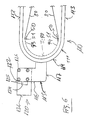
- Fig. 6 shows in a plan view the embodiment of the present device shown in Fig. 5, after the non-essential for this embodiment components of the present device have been omitted for the sake of clarity.
- a holding device 110 is arranged for this end part of the legwear. This area is located above the lower end of the carrier 3, which may be inserted in the base plate 1.
- the holding device 110 comprises a bracket 111 to which the edge of the open end portion of the legwear can be connected. This bracket 111 is in a horizontal plane and it is U-shaped.
- the bracket 111 has two mutually parallel legs 112 and 113. The one ends of these legs 112 and 113 are connected to each other by means of a web 114 to said U-shape.
- the web 114 is arcuate.
- a connection plate 115 is attached at one end, which also lies at least substantially in said horizontal plane.
- this connection plate 115 is L-shaped, so that it has two legs 116 and 117. The free end portion of one of the L-legs 117 of the connection plate 115 is connected to the web 114 of the bracket 111.
- the holding device 110 further comprises a mechanism 120, which for Adjustment of the position of the bracket 111 relative to the support 3 in the horizontal direction allows.
- the adjustment mechanism 120 comprises two vertically extending rods 121 and 122 which are substantially parallel to each other and which are associated with each other so that one of the rods can slide along the other rod.
- these rods 121 and 122 have a quadrangular cross-section and they are associated with one another via one of their side surfaces.
- Means 123 are provided, with the aid of which the set position of one of the rods relative to the other rod can be determined.
- These means 123 may comprise, for example, a screw and a nut.
- the bolt of the screw passes through the two rods 121 and 122.
- the position of the rods 121 and 122 to each other can be determined in such a way that a nut is tightened on the other end of the bolt.
- a longitudinal groove 124 is made in the side surface of one of the rods 121 to which the other rod 122 is assigned.
- the corresponding side surface of this other rod 122 is provided with a protruding comb 125 which projects from this side wall of the rod 122 and which is mounted longitudinally displaceably in the groove 124.
- the lower end portion of the first and lower rod 121 is fixed on or in the base plate 1.
- the free end portion of the second L-leg 116 of the connection plate 115 is connected to the bracket 111 to the upper end of the second rod 122.
- screw holes are executed in the end face of this end of the second rod 122 .
- the screw holes corresponding openings 126 are executed.
- Means screws (not shown), which pass through these openings 126, the free end portion of the second L-leg 116 may be attached to the end face of the second rod.
- two sensor devices 50 are provided, with the pressure sensors 51 within the respective group forming a substantially vertical row.
- One of each of these sensor rows 50 is assigned to one of the flanks 93 or 94 of the carrier 3 with the arc-shaped cross-section.
- the active surfaces of the sensors 51 of these rows 50 are located on the outside of the respective flank 93 or 94 of the carrier 3.
- the carrier 3 together with the sensor rows 50 are surrounded by the leg clothing 80, of which in Fig. 6, only the front portion thereof indicated is.
Abstract
Description
Die vorliegende Erfindung betrifft eine Einrichtung zum Testen von elastischen textilen Beinbekleidungen, insbesondere von Strümpfen oder Strumpfhosen, von medizinischen Kompressions-Strümpfen und Stützstrümpfen.The present invention relates to a device for testing elastic textile leg garments, in particular stockings or tights, medical compression stockings and support stockings.
Elastische textile Beinbekleidungen müssen so geformt sein, dass sie dem Umriss des Beins der die Beinbekleidung tragenden Person möglichst genau folgen. Denn nur in einem solchen Fall kann die Beinbekleidung ihre Funktion voll ausüben, ohne dass es Stellen entlang dem Bein gibt, an welchen die Beinbekleidung entweder einen zu grossen oder einen zu kleinen Druck ausübt. Um dies zu erreichen, ist es bekannt, das Bein des Trägers der Beinbekleidung zunächst zu vermessen. Diese Vermessung wird in der Weise durchgeführt, dass der Umfang des Beines an bestimmten Stellen des Beines gemessen wird. Bei dieser Vermessung misst man beispielsweise den Umfang des Beines im Bereich der Fessel, am Anfang, in der Mitte und am oberen Ende der Wade, im Kniebereich und im Bereich des Oberschenkels, nämlich in der Mitte und am oberen Ende desselben. Wenn es sich um eine Strumpfhose handelt, dann wird der Umfang auch im Bereich des Gesässes und gegebenenfalls auch im Bereich der Taille gemessen. Aufgrund dieser Vorgaben wird die Beinbekleidung dann hergestellt. Hiernach ist es allerdings auch erforderlich zu ermitteln, ob die Vorgaben beim hergestellten Produkt eingehalten worden sind.Elastic textile leg garments must be shaped so as to follow as closely as possible the contour of the leg of the person wearing the garment. For only in such a case can the legwear perform its function fully, without there being any points along the leg where the legwear either exerts too much or too little pressure. To achieve this, it is known to first measure the wearer's leg. This measurement is performed by measuring the circumference of the leg at specific locations on the leg. For example, this measurement measures the circumference of the leg in the area of the ankle, at the beginning, in the middle and at the top of the calf, in the knee area and in the area of the thigh, namely in the middle and at the upper end. If it is a tights, then the circumference is also measured in the area of the buttocks and possibly also in the area of the waist. Based on these specifications, the legwear is then produced. According to this, however, it is also necessary to determine whether the specifications for the manufactured product have been complied with.
Bereits sind Einrichtungen zur Vermessung fertiger Strümpfe bekannt. Bei einer dieser Einrichtungen werden die einander gegenüberliegenden Längsränder des flachgelegten Strumpfes auf Nadeln aufgesteckt, welche zwei Reihen entlang der Strumpflänge bilden. Diese Nadeln sind beweglich gelagert, und zwar derart, dass der Abstand zwischen zwei einander gegenüberliegenden Nadeln der Nadelreihen geändert werden kann. Die Messung, ob die Vorgaben während der Herstellung des Strumpfes eingehalten worden sind, kann beispielsweise in der Weise erfolgen, dass einander gegenüberliegende Nadeln in Abstände voneinander gebracht werden, welche den Vorgabe entsprechen und dass die Spannung im Strumpf zwischen zwei einander gegenüberliegenden Nadeln gemessen wird. So kann man zwar feststellen, ob die Kontur des Strumpfes den durch die Vorgaben bestimmten Verlauf aufweist. Wegen dem Aufspiessen auf die Nadeln wird der vermessene Strumpf jedoch unverkäuflich. Wenn man bedenkt, dass solche Strümpfe oft Einzelanfertigungen sind, dann ist die Vermessung der fertigen Strümpfe mit Hilfe der soeben genannten Einrichtung uneffektiv.Already facilities for measuring finished stockings are known. In one of these devices, the opposite longitudinal edges of the flattened stocking are attached to needles, which form two rows along the stocking length. These needles are movably mounted in such a way that the distance between two opposite Needles of the needle rows can be changed. The measurement as to whether the specifications have been met during the production of the stocking can, for example, be such that opposing needles are spaced apart from each other in accordance with the specification and that the tension in the stocking between two opposite needles is measured. So you can indeed determine whether the contour of the stocking has the course determined by the requirements. Because of the impingement on the needles the measured stocking is not for sale. Considering that such stockings are often custom-made, then the measurement of the finished stockings using the just mentioned device is ineffective.
Die Aufgabe der vorliegenden Einrichtung ist, den genannten sowie noch weitere Nachteile des Standes der Technik zu beseitigen.The object of the present device is to eliminate the mentioned as well as still further disadvantages of the prior art.
Diese Aufgabe wird bei der Einrichtung der eingangs genannten Gattung in der Weise gelöst, wie dies im kennzeichnenden Teil des Patentanspruchs 1 definiert ist.This object is achieved in the device of the type mentioned in the manner as defined in the characterizing part of
Nachstehend werden Ausführungsformen der vorliegenden Erfindung anhand den beiliegenden Zeichnungen näher erläutert. Es zeigt:
- Fig. 1 das Modell eines menschlichen Beines, an dem demonstriert werden kann, an welchen Stellen des Beines Umfangsmessungen durchgeführt werden können,
- Fig. 2 in einer Seitenansicht eine erste Ausführungsform der vorliegenden Einrichtung, welche grösstenteils mit Hilfe eines kinematischen Schemas dargestellt ist,
- Fig. 3 vergrössert einen Ausschnitt aus Fig. 2,
- Fig. 4 einen bloss schematischen horizontalen Schnitt A-A durch eine weitere Ausführung der vorliegenden Erfindung, welche der Einrichtung gemäss Fig. 2 entspricht,
- Fig. 5 eine noch weitere Ausführungsform der vorliegenden Einrichtung, deren
- Darstellung weitgehend der Darstellung in Fig. 2 entspricht und
- Fig. 6 in einer Draufsicht die in Fig. 5 dargestellte Ausführungsform der vorliegenden Einrichtung.
- 1 shows the model of a human leg, at which it can be demonstrated at which points of the leg circumference measurements can be performed,
- 2 is a side view of a first embodiment of the present device, which is largely represented by means of a kinematic scheme,
- 3 enlarges a section of FIG. 2,
- 4 shows a purely schematic horizontal section AA through a further embodiment of the present invention, which corresponds to the device according to FIG. 2 corresponds,
- Fig. 5 shows a still further embodiment of the present device, whose
- Representation largely corresponds to the illustration in Fig. 2 and
- Fig. 6 is a plan view of the embodiment shown in Fig. 5 of the present device.
Fig. 1 zeigt das Modell eines menschlichen Beines, an dem demonstriert werden kann, an welchen Stellen bzw. in welchen Bereichen des menschlichen Körpers Umfangsmessungen durchgeführt werden können, um die Beinbeklei- ' dungen, wie z.B. medizinische Strümpfe oder Strumpfhosen anfertigen zu können. Im Prinzip könnte man auch den Fuss der Beinbekleidung vermessen. Für die Zwecke des vorliegenden Falles werden hier Messungen nur oberhalb des Fusses berücksichtigt. Während einer solchen Vermessung misst man beispielsweise den Umfang des Beines im Bereich der Fessel cB, am Anfang cB1 der Wade, in der Mitte cC der Wade und am oberen Ende cD der Wade, im Kniebereich cE, in der Mitte cF des Oberschenkels und am oberen Ende cG desselben. Wenn es sich um die Herstellung einer Strumpfhose handelt, dann wird auch der Umfang cH im Bereich des Gesässes und der Umfang cT der Taille vermessen.Fig. 1 shows the model of a human leg, which can be used to demonstrate at which points or in which areas of the human body circumference measurements can be made in order to fit the leg pieces, e.g. to make medical stockings or tights. In principle, one could also measure the foot of the legwear. For the purposes of the present case, measurements are taken only above the foot. During such a measurement, for example, measure the circumference of the leg in the area of the ankle cB, at the beginning cB1 of the calf, in the middle cC of the calf and at the upper end cD of the calf, in the knee area cE, in the middle cF of the thigh and at the top End cG of the same. When it comes to the production of pantyhose, the circumference cH in the area of the buttocks and the circumference cT of the waist are also measured.
Die menschlichen Beine unterscheiden sich voneinander nicht nur durch die Grösse des Umfanges in den genannten Bereichen desselben sondern auch durch die Abstände zwischen diesen Bereichen. Diese Abstandsunterschiede sind durch die unterschiedliche Länge der Beine bedingt. Deswegen werden auch diese Längen während der Vermessungen eines Beines ermittelt. Diese Längen werden zweckmässigerweise auf die Fussunterseite, insbesondere auf die Unterseite der Ferse bezogen. Der Bereich der Fessel cB befindet sich im Abstand LB von der Ferse usw., wie dies in Fig. 1 rechts angegeben ist.The human legs differ from each other not only by the size of the circumference in said areas but also by the distances between these areas. These differences in distance are due to the different lengths of the legs. Therefore, these lengths are also determined during the measurements of a leg. These lengths are conveniently based on the underside of the foot, in particular on the underside of the heel. The area of the tether cB is located at a distance LB from the heel, etc., as indicated on the right in FIG.
Die vorliegende Einrichtung zum nicht zerstörenden Prüfen von elastischen textilen Beinbekleidungen, wie z.B. von Strümpfen, Strumpfhosen usw. ist so ausgeführt, dass sie erlaubt, die in den betreffenden Bereichen eines Beines gemessenen Umfangswerte in den entsprechenden Bereichen der Einrichtung einzustellen. Ferner ermöglicht die vorliegende Einrichtung, die Grösse der Spannung zu messen, welche in jenen Bereichen der Beinbekleidung herrschen, die den genannten Bereichen des Beines entsprechen. Dies garantiert dafür, dass das fertige Produkt nicht nur seine die Gesundheit unterstützende Wirkung ausübt sondern dass sich die Beinbekleidung auch komfortabel tragen lässt.The present device for non-destructive testing of elastic Textile legwear, such as stockings, tights, etc., is designed to allow adjustment of circumference values measured in the respective areas of a leg in the respective areas of the facility. Further, the present device allows to measure the amount of tension that prevail in those areas of the legwear corresponding to said areas of the leg. This guarantees that the finished product does not only exert its health-promoting effect, but that the legwear can also be worn comfortably.
Fig. 2 zeigt in einer Seitenansicht eine der Ausführungsformen der vorliegenden Einrichtung. Fig. 3 zeigt einen vergrösserten Ausschnitt aus dem oberen Bereich von Fig. 2. Die vorliegende Einrichtung ist grösstenteils anhand eines sogenannten kinematischen Schemas dargestellt. Dieses Schema zeigt unter anderem auch das Prinzip der vorliegenden Einrichtung für einen bestimmten Bereich des Beines. Dieses Prinzip lässt sich dann in einer Einrichtung dieser Art wiederholt anwenden, um mehrere Bereiche einer Beinbekleidung zu prüfen.Fig. 2 shows in a side view one of the embodiments of the present device. 3 shows an enlarged detail from the upper area of FIG. 2. The present device is largely represented by a so-called kinematic scheme. This scheme also demonstrates, inter alia, the principle of the present device for a particular area of the leg. This principle can then be used repeatedly in a device of this type to test several areas of a legwear.
Die vorliegende Einrichtung weist eine Grundplatte 1 auf, auf welcher sich eine Hauptstütze 2 der vorliegenden Einrichtung befindet. Diese Hauptstütze 2 hat einen länglichen Grundkörper 3, welcher im wesentlichen als eine hohle Schiene ausgeführt ist. Diese Schiene 3 hat im in Fig. 2 bzw. 3 dargestellten Fall einen etwa U-förmigen Querschnitt. Diese Schiene 3 kann jedoch auch einen L-förmigen oder sogar einen viereckförmigen Querschnitt aufweisen. Die in der Grundplatte 1 eingesteckte Hauptstütze 2 ist kein zwingender Bestandteil der vorliegenden Einrichtung. Wichtig ist vor allem die Schiene 3, welcher die übrigen Bestandteile der vorliegenden Einrichtung zugeordnet sind. In Fig. 2 und 3 ist nur der vorne liegende Schenkel 4 der Schiene 3 mit dem U-förmigen Querschnitt dargestellt. Dieser vorne liegende U-Schenkel 4 ist über einen Verbindungssteg 5 mit dem zweiten U-Schenkel verbunden, welcher hinter dem vorderen U-Schenkel 4 liegt und durch diesen daher verdeckt ist. Zumindest die Aussenfläche 6 des Verbindungssteges 5 ist abgerundet. Es kann zweckmässig sein, auch die Innenfläche 7 des Verbindungssteges 5 entsprechend der abgerundeten Aussenfläche 6 desselben hohl auszuführen.The present device comprises a
Die obere Endpartie der Hauptstütze 2 bzw. der Schiene 3 weist einen seitlich abgebogenen Abschnitt 8 auf. Dieser Schienenabschnitt 8 ist so abgebogen, dass er oberhalb des Verbindungssteges 5 der Schiene 3 liegt und sich zur Längsrichtung dieser Schiene 3 schräg aufwärts erstreckt. Dieser im wesentlichen hakenförmige Abschnitt 8 der Hauptstütze 2 simuliert den Bereich der Spitze eines Fusses. Bei einer weiteren Ausführungsform der vorliegenden Einrichtung kann der Bereich der Fussspitze 8 als ein Abschnitt eines schräg aufwärts verlaufenden, hohlen Formstückes, beispielsweise aus einem Kunststoff ausgeführt sein. Dieses Formstück ist den übrigen und nachstehend beschriebenen Bestandteilen dieser Einrichtung vorangestellt. Der Querschnitt dieses Formstückes kann bogenförmig verlaufen, und zwar etwa so, wie dies vorstehend im Zusammenhang mit dem Querschnitt der Hauptstütze 3 dargelegt ist.The upper end portion of the
Die vorliegende Einrichtung umfast ferner Messvorrichtungen 10. Die jeweilige Messvorrichtung 10 umfasst einen Hebelmechanismus und wenigstens einen Drucksensor 51. Die sich an der Messung aktiv beteiligenden Bestandteile der jeweiligen Messvorrichtung 10 befinden sich jeweils auf jenem Niveau L einer Beinbekleidung, wo Druckmessungen durchgeführt werden sollen. Zu diesem Zweck sind zumindest die Wirkflächen der Drucksensoren 51 an der Aussenfläche 6 der Schiene 3 angebracht. Deswegen kann die Schiene 3 auch als Träger der Drucksensoren 51 genannt werden. Die Drucksensoren 51 sind zu zumindest einer vertikal verlaufenden Sensorvorrichtung 50 zusammengefasst, wobei die Drucksensoren 51 innerhalb einer Sensorvorrichtung 50 eine Reihe bilden. Im in Fig. 2 und 3 dargestellten Fall befindet sich die Sensorvorrichtung 50 vorne in der Mitte der Frontfläche 5 des Trägers 3. Zweckmässiger ist es jedoch, wenn es zwei Sensorvorrichtungen 50 gibt, von welchen je eine einer der Flanken bzw. einem der Schenkel 4 des Trägers 3 zugeordnet ist. Die Wirkflächen der Drucksensoren 51 der Sensorvorrichtungen 50 befinden sich an der Aussenfläche der Schenkel 4 des Trägers 3. Jeder der Drucksensoren 51 ist einzeln an eine zentrale Auswerteeinheit (nicht dargestellt) elektrisch angeschlossen.The present device further comprises measuring devices 10. The respective measuring device 10 comprises a lever mechanism and at least one
Im oberen Bereich von Fig. 2 ist neben anderem auch eine erste der genannten Messvorrichtungen 10 dargestellt, welche zur Messung des Druckes im Bereich cB der Fessel bestimmt und ausgeführt ist. Dieser Bereich der vorliegenden Einrichtung ist in Fig. 3 vergrössert dargestellt. Die Messvorrichtung 10 umfasst neben anderem auch einen Hebelmechanismus 11 (Fig. 3), welcher einen ersten Hebel 12 aufweist. Dieser Hebel 12 erstreckt sich im wesentlichen vertikal. Das unten liegende Ende 13 dieses ersten Hebels 12 ist im dargestellten Beispiel an der Hauptstütze 2 unterhalb der Abkröpfung 8 mittels einer Achse 23 schwenkbar gelagert. Zweckmässigerweise ist dieses untere Ende 13 des ersten Hebels 12 am in Fig. 2 bzw. 3 im Vordergrund liegenden U-Schenkel 4 des Stützengrundkörpers 3 schwenkbar gelagert. Das obere Ende 14 des ersten Hebels 12 befindet sich etwa auf der Höhe des hakenförmigen Ausläufers 8 des Stützengrundkörpers 3. Das obere Ende 14 des ersten Hebels 12 weist ebenfalls einen seitlich abgebogenen Ausläufer 15 auf, welcher allerdings so abgebogen ist, dass er in einer zur Richtung der Abkröpfung 8 am Stützengrundkörper 3 entgegengesetzten Richtung zeigt. Der Ausläufer bzw. die Abkröpfung 15 am oberen Ende 14 des ersten Hebels 12 simuliert die Ferse eines Fusses bzw. einer Beinbekleidung.In the upper area of FIG. 2, among other things, a first of the mentioned measuring devices 10 is shown, which is intended and designed for measuring the pressure in the area cB of the shackle. This area of the present device is shown enlarged in FIG. 3. The measuring device 10 also includes, among other things, a lever mechanism 11 (FIG. 3) which has a
Der Hebelmechanismus 11 weist ferner einen zweiten Hebel 16 auf, welcher sich ebenfalls im wesentlichen vertikal erstreckt. Dieser zweite Hebel 16 kreuzt den ersten Hebel 12. Diese Hebel 12 und 16 sind im Bereich ihrer Kreuzungsstelle mit Hilfe einer Achse 17 miteinander schwenkbar verbunden. Diese sich so zugeordneten Hebel 12 und 16 bilden einen sogenannten Scherenmechanismus. Die genannte Achse 17 liegt im dargestellten Fall etwa in der Mitte der Länge der genannten Hebel 12 und 16. Das oben liegende Ende 18 des zweiten Hebels 16 dieses Scherenmechanismus 11 liegt im dargestellten Beispiel auf der Innenfläche 7 des Stützengrundkörpers 3 auf.The
Das unten liegende Ende 19 des zweiten Hebels 16 ist an die Spindelmutter 24 eines Spindelantriebs 25 für den Wert cB angeschlossen. Dieser Spindelantrieb 25 ist horizontal orientiert und er ist am Stützengrundkörper 3 etwa dort angebracht, wo das untere Ende 13 des ersten Hebels 12 schwenkbar gelagert ist. Der Spindelantrieb 25 ist so angeordnet und ausgeführt, dass er die unteren Enden 13 und 19 der Hebel 12 und 16 des Scherenmechanismus 11 gegeneinander zu und voneinander weg bewegen kann. Dementsprechend wird der Abstand zwischen den Abkröpfungen 8 und 15 an den oberen Enden dieser Hebel 12 und 16 vermindert oder vergrössert.The
Eine Stange 21 ist mittels eines Gelenks 22 am oberen Schenkel 20 des ersten Hebels 12 einerends schwenkbar angebracht. Dieses Gelenk 22 befindet sich unterhalb der Abkröpfung 15 des ersten Hebels 12, sodass dieses Gelenk 22 an der von den Drucksensoren 51 abgewandten Seite des oberhalb der Schwenkachse 17 liegenden Schenkels 20 des ersten Hebels 12 liegt. Das Gelenk 22 befindet sich in einem Abstand 28 unterhalb der Abkröpfung 15 am oberen Ende 14 des ersten Hebels 12. Innerhalb dieses Abschnittes 28 des Hebels 12, welcher sich zwischen der Abkröpfung 15 und dem Gelenk 22 erstreckt, liegt jenes Niveau der vorliegenden Einrichtung, wo die Messung des Wertes cB durchgeführt wird, und zwar unter Zuhilfenahme des zuoberst liegenden Drucksensors 51. Weil der genannte Abschnitt 28 einen festen Bestandteil des ersten Hebels 12 darstellt, kann der Abstand zwischen vom Sensor 51 und der von diesem abgewandt liegenden Fläche 28 am Hebel 12 mit Hilfe des genannten ersten Spindelantriebs 25 ebenfalls verstellt werden.A
Damit die Lage der Ferse 15 und somit auch des Messniveaus cB in einer vertikalen Richtung geändert werden kann, womit die Länge des Beines während der Herstellung der Beinbekleidung berücksichtigt werden kann, ist das Schwenklager 23 des unteren Endes 13 des ersten Hebels 12 an der Spindelmutter eines vertikal orientierten und fest möntierten Spindelantriebs 29 befestigt.Thus, the position of the heel 15 and thus the measurement level cB can be changed in a vertical direction, so that the length of the leg can be considered during the manufacture of legwear, the pivot bearing 23 of the lower end 13 of the
Im oberen Bereich von Fig. 2 sind ferner aktive Teile einer zweiten Messvorrichtung 30 dargestellt, welche zur Messung des Druckes im Bereich cB1 des Anfangs der Wade bestimmt und ausgeführt ist. Diese Messvorrichtung 30 umfasst unter anderem auch einen Hebelmechanismus 31, welcher einen ersten Hebel 32 aufweist. Dieser Hebel 32 erstreckt sich im wesentlichen vertikal. Das unten liegende Ende 33 dieses ersten Hebels 32 ist schwenkbar gelagert. Zweckmässigerweise ist dieses Ende 13 des ersten Hebels 32 am in Fig. 2 bzw. 3 vorne liegenden U-Schenkel 4 des Stützengrundkörpers 3 mittels einer Welle 43 schwenkbar gelagert. Das obere Ende 34 des ersten Hebels 32 befindet sich in einem Abstand unterhalb der Abkröpfung 15 am ersten Hebel 12 und es ist der Stange 27 zugeordnet. In dieser Stange 27 ist ein Schlitz (nicht dargestellt) ausgeführt, welcher sich zwischen den Enden dieser Stange erstreckt. Dieser Schlitz beginnt und endet in einem Abstand von den Enden dieser Stange 21. In diesem Schlitz ist das obere Ende 34 des ersten Hebels 32 der zweiten Messvorrichtung 30 längsverschiebbar gelagert.Also shown in the upper part of FIG. 2 are active parts of a
Der zweite Hebelmechanismus 31 weist ferner einen zweiten Hebel 36 auf, welcher sich ebenfalls im wesentlichen vertikal erstreckt. Dieser zweite Hebel 36 kreuzt den ersten Hebel 32. Diese Hebel 32 und 36 sind im Bereich ihrer Kreuzungsstelle mit Hilfe einer Achse 37 miteinander schwenkbar verbunden. Diese sich so zugeordneten Hebel 32 und 36 bilden somit einen zweiten Scherenmechanismus. Die genannte Achse 37 liegt im dargestellten Fall oberhalb der Mitte der Länge der genannten Hebel 32 und 36. Das oben liegende Ende 38 des zweiten Hebels 36 dieses Scherenmechanismus 31 stützt sich im dargestellten Fall am oberen Schenkel 20 des ersten Hebels 12 des ersten Scherenmechanismus 11 ab. Unter Umständen wäre es möglich, dass das oben liegende Ende 38 des zweiten Hebels 36 dieses zweiten Scherenmechanismus 31 auf der Innenfläche 7 des Stützengrundkörpers 3 aufliegt.The
Das unten liegende Ende 39 des zweiten Hebels 36 ist an die Spindelmutter 44 eines zweiten Spindelantriebs 45 für den Wert cB1 angeschlossen. Dieser Spindelantrieb 45 ist horizontal orientiert und er ist etwa dort angebracht, wo das untere Ende 33 des ersten Hebels 32 mittels der Welle 43 schwenkbar gelagert ist. Der Spindelantrieb 45 ist so angeordnet und ausgeführt, dass er die unteren Enden 33 und 39 der Hebel 32 und 36 des zweiten Scherenmechanismus 31 gegeneinander zu und voneinander weg bewegen kann.The lower end 39 of the
Dementsprechend wird der Abstand zwischen den oberen Enden 34 und 38 der Hebel 32 und 36 vermindert oder vergrössert. Wenn der Abstand zwischen den oberen Enden 34 und 38 der Hebel 32 und 36 geändert wird, dann bewegt sich das obere Ende 34 des ersten Hebels 32 nach rechts. Da dieses Ende 34 des ersten Hebels 32 in der Stange 21 gelagert ist, vergrössert sich dabei ein Winkel Alpha, welcher sich zwischen dem oberen Schenkel 20 des ersten Hebels 12 und der Stange 21 erstreckt. Dadurch ändert sich auch der Abstand zwischen der Rückseite der Stange 21 und dem auf demselben Niveau liegenden Drucksensor 51. In dieser Weise können unterschiedliche Grössen des Umfanges des Beines im Bereich cB1 des Anfangs der Wade eingestellt werden.Accordingly, the distance between the upper ends 34 and 38 of the
Damit die Lage des Messbereichs cB1 in einer vertikalen Richtung geändert werden kann, womit die Länge des Beines eines Patienten berücksichtigt werden kann, kann die Lagerwelle 43 des ersten Hebels 32 an der Spindelmutter des bereits genannten vertikal orientierten Linearantriebs 29 (Fig. 2) gelagert sein.So that the position of the measuring range cB1 can be changed in a vertical direction, taking into account the length of the leg of a patient can, the bearing shaft 43 of the
Im oberen Bereich von Fig. 2 sind aktive Teile auch einer dritten Messvorrichtung 60 dargestellt, welche zur Messung des Druckes im Bereich cC der Mitte der Wade bestimmt und ausgeführt ist. Diese Messvorrichtung 60 umfasst unter anderem auch einen Hebelmechanismus 61, welcher einen ersten Hebel 62 aufweist. Dieser Hebel 62 erstreckt sich im wesentlichen vertikal. Das unten liegende Ende 63 dieses ersten Hebels 62 ist schwenkbar gelagert. Zweckmässigerweise ist dieses Ende 63 des ersten Hebels 62 mittels einer Welle 53 schwenkbar gelagert. Dem oberen Ende 64 des ersten Hebels 62 ist ein längliches Formstück 48 zugeordnet. Das oben liegende Ende 46 dieses Formstücks 48 ist der Stange 21 gleitbar zugeordnet. Das unten liegende Ende 47 des Formstückes 48 ist über ein Gelenk 65 am oben liegende Ende 64 des ersten Hebels 62 schwenkbar gelagert. Das Formstück 48 ist so ausgeführt, dass seine von den Drucksensoren 51 abgewandte Seite eine Oberfläche aufweist, welche der Oberfläche der Rückseite einer Wade ähnelt.In the upper part of FIG. 2, active parts are also shown in a
Dieser dritte Hebelmechanismus 61 weist ferner einen zweiten Hebel 66 auf, welcher sich ebenfalls im wesentlichen vertikal erstreckt. Dieser zweite Hebel 66 kreuzt den ersten Hebel 62. Diese Hebel 62 und 66 sind im Bereich ihrer Kreuzungsstelle mit Hilfe einer Achse 67 miteinander schwenkbar verbunden. Diese sich so zugeordneten Hebel 62 und 66 bilden somit einen dritten Scherenmechanismus. Das oben liegende Ende 68 des zweiten Hebels 66 dieses Scherenmechanismus 61 ist gleitbar abgestützt. Das unten liegende Ende 69 des zweiten Hebels 66 ist an die Spindelmutter 54 eines dritten Spindelantriebs 55 für den Wert cC angeschlossen. Dieser Spindelantrieb 55 ist horizontal orientiert und er ist etwa dort angebracht, wo das untere Ende 63 des ersten Hebels 62 mittels der Welle 53 schwenkbar gelagert ist.This
Der Spindelantrieb 55 ist so angeordnet und ausgeführt, dass er die unteren Enden 63 und 99 der Hebel 62 und 66 des dritten Scherenmechanismus 61 gegeneinander zu und voneinander weg bewegen kann. Dementsprechend wird der Abstand zwischen den oberen Enden 64 und 68 der Hebel 62 und 66 vermindert oder vergrössert. Wenn der Abstand zwischen den oberen Enden 64 und 68 der Hebel 62 und 66 vergrössert wird, dann bewegt sich das obere Ende 64 des ersten Hebels 62 nach rechts. Da das untere Ende 47 des Formstückes 48 an das obere Ende 64 des ersten Hebels 62 angeschlossen ist, bewegt sich das untere Ende 47 des Formstückes 48 ebenfalls nach rechts, womit sich der Abstand zwischen der rückwärtigen Oberfläche am Formstück 48 und den auf demselben Niveau liegenden Drucksensoren 51 vergrössert. In dieser Weise können unterschiedliche Grössen des Umfanges des Beines im Bereich cC der Wade in der vorliegenden Einrichtung eingestellt werden.The
Damit die Lage des Messbereichs LC in einer vertikalen Richtung geändert werden kann, womit die Länge des Beines eines Patienten berücksichtigt werden kann, ist die Lagerwelle 63 des ersten Hebels 62 an einem zweiten vertikal orientierten Linearlager 49 angebracht.In order to be able to change the position of the measuring area LC in a vertical direction, taking into account the length of the leg of a patient, the bearing shaft 63 of the
In Fig. 2 ist noch eine vierte Messvorrichtung 70 dargestellt, mit welcher die Abmessungen im Bereich eines menschlichen Oberschenkels eingestellt werden können und mit welcher die Messungen von Druck zwischen den Bereichen cD und cG (Fig. 1) durchgeführt werden können. Diese Messvorrichtung 70 umfasst unter anderem auch ein zweites längliches Formstück 88. Die von den Drucksensoren 51 abgewandt liegende Oberfläche 89 des Formstückes 88 hat einen Verlauf, welcher dem Verlauf der Oberfläche der rückwärtigen Seite des Oberschenkels entspricht. Das untere Ende 87 dieses Formstückes 88 ist an die Mutter eines weiteren horizontal orientierten Spindelantriebs 84 angeschlossen, welcher die Einstellung des Werte cG (Fig. 1) im oberen Bereich LG des Oberschenkels ermöglicht.FIG. 2 also shows a
Diese Messvorrichtung 70 umfasst ferner einen vierten Hebelmechanismus 71, welcher einen ersten Hebel 72 aufweist. Dieser Hebel 72 erstreckt sich im wesentlichen vertikal. Das unten liegende Ende 73 dieses ersten Hebels 72 ist schwenkbar gelagert. Zweckmässigerweise ist dieses Ende 73 des ersten Hebels 72 mittels einer Welle 85 schwenkbar gelagert. Dem oberen Ende 74 des ersten Hebels 72 ist das obere Ende 86 des zweiten länglichen Formstückes 88 schwenkbar zugeordnet.This measuring
Dieser vierte Hebelmechanismus 71 weist ferner einen zweiten Hebel 76 auf, welcher sich ebenfalls im wesentlichen vertikal erstreckt. Dieser zweite Hebel 76 kreuzt den ersten Hebel 72. Diese Hebel 72 und 76 sind im Bereich ihrer Kreuzungsstelle mit Hilfe einer Achse 77 miteinander schwenkbar verbunden. Diese sich so zugeordneten Hebel 72 und 76 bilden somit einen vierten Scherenmechanismus. Das oben liegende Ende 78 des zweiten Hebels 76 dieses Scherenmechanismus 71 ist gleitbar abgestützt. Das unten liegende Ende 79 des zweiten Hebels 76 ist an die Spindelmutter eines weiteren Spindelantriebs 95 für die Einstellung des Wertes cD angeschlossen. Dieser Spindelantrieb 95 ist horizontal orientiert und er ist etwa dort angebracht, wo das untere Ende 73 des ersten Hebels 72 mittels der Welle 85 schwenkbar gelagert ist.This
Der Spindelantrieb 95 ist so angeordnet und ausgeführt, dass er die unteren Enden 73 und 79 der Hebel 72 und 76 dieses Scherenmechanismus 71 gegeneinander zu und voneinander weg bewegen kann. Dementsprechend wird der Abstand zwischen den oberen Enden 74 und 78 der Hebel 72 und 76 vermindert oder vergrössert. Wenn der Abstand zwischen den oberen Enden 74 und 78 der Hebel 72 und 76 vergrössert wird, dann bewegt sich das obere Ende 74 des ersten Hebels 72 nach rechts. Das obere Ende 86 des Formstückes 88 ist an das obere Ende 74 des ersten Hebels 72 angeschlossen. Deswegen bewegt sich das obere Ende 86 des Formstückes 88 ebenfalls nach rechts, womit sich der Abstand zwischen der rückwärtigen Oberfläche am Formstück 88 und den auf demselben Niveau liegenden Drucksensoren 51 vergrössert. In dieser Weise können unterschiedliche Grössen des Umfanges des Beines im unteren Bereich LD des Oberschenkels in der vorliegenden Einrichtung eingestellt werden.The
Damit die Lage LG der Messbereiche cG und cD in einer vertikalen Richtung geändert werden kann, womit die Länge des Beines eines Patienten berücksichtigt werden kann, sind die Lagerwelle 85 des ersten Hebels 72 und der Spindelantrieb 84 an einem weiteren vertikal orientierten Linearlager 99 angebracht.In order that the position LG of the measurement ranges cG and cD may be changed in a vertical direction, taking into account the length of the leg of a patient, the bearing
Die Hebel aller Scherenmechanismen können als Flacheisen ausgeführt sein, sodass der jeweilige Scherenmechanismus sehr flach ausfällt. Folglich nehmen mehrere sich gegenseitig flach zugeordnete Scherenmechanismen ein nur geringes Volumen ein, sodass auch eine grössere Anzahl solcher Scherenmechanismen im Inneren einer Beinbekleidung 80 Platz finden können.The levers of all scissors mechanisms can be designed as flat iron, so that the respective scissors mechanism is very flat. Consequently, a plurality of mutually shallow associated scissor mechanisms occupy only a small volume, so that a larger number of such scissor mechanisms can find space inside a
Fig. 4 zeigt einen bloss schematischen horizontalen Schnitt A-A durch eine weitere Ausführung der vorliegenden Erfindung, welche der Einrichtung gemäss Fig. 2 entspricht. Die Einrichtung gemäss Fig. 4 weist den länglichen und vertikal verlaufenden Träger 90 für die Drucksensoren 51 auf. Dieser Träger 90 ist den vorstehend beschriebenen Hebelmechanismen 10 vorangestellt ist. Die obere Endpartie dieses Trägers 90 kann die vorstehend genannte Abkröpfung 8 (Fig. 2) aufweisen, welche die Spitze eines Fusses simuliert. Der Querschnitt dieses Trägers 90 ist bogenförmig, wobei der Zentriwinkel dieses Bogens zweckmässigerweise 180 Grad aufweist. Ein solcher Träger 90 weist zwei Flanken 93 und 94 mit zwei sich vertikal erstreckende Randpartien 91 und 92 auf. Dieser Träger 90 simuliert in der vorliegenden Einrichtung für die Beinbekleidung den Bereich des Schienbeines.Fig. 4 shows a purely schematic horizontal section AA through a further embodiment of the present invention, which corresponds to the device according to FIG. 2. The device according to FIG. 4 has the elongate and vertically extending
Die gekrümmte Fläche 89 am Formstück bzw. Gegenlager 88, das in Fig. 4 dargestellt ist, simuliert in der vorliegenden Einrichtung dagegen die rückwärtige Oberfläche des Oberschenkels. Bei dieser Ausführungsform der vorliegenden Einrichtung sind zwei Gruppen 50 von Drucksensoren 51 vorgesehen, wobei die Drucksensoren 51 innerhalb der jeweiligen Gruppe eine praktisch vertikal verlaufende Reihe bilden. Je eine dieser Reihen 50 von Drucksensoren 51 ist der Aussenseite einer der Flanken 93 bzw. 94 oder der Aussenseite einer der Randpartien 91 bzw. 92 des Trägers 90 zugeordnet. Der Träger 90 samt den Sensorreihen 50 und das Formstück 88 sind von der Beinbekleidung 80 umgeben. Zwischen den Vertikalkanten 91 und 92 des Trägers 90 und den Vertikalkanten 78 und 79 des Formstückes 88 erstrecken sich die dazwischen frei stehenden Abschnitte 81 und 82 der über diese Einrichtung überstülpten Beinbekleidung 80.The
Zwischen den Flanken 93 und 94 des Trägers 90 mit dem bogenförmigen Querschnitt liegen die vorderen Abschnitte der genannten Hebelmechanismen 11, 31, 61 und 71. Aus dem in Fig. 4 dargestellten Schnitt ist auch ersichtlich, dass diese Ausführung der vorliegenden Einrichtung zwei Anordnungen 101 und 102 aufweist, von welchen jede die vorstehend beschriebenen Hebelmechanismen 11, 31, 61 und 71 aufweist. Jede dieser Anordnungen 101 und 102 ist im wesentlichen flach, weil die Hebel der Hebelmechanismen 11, 31, 61 und 71 aus Flacheisen sind. Solche flache Anordnungen 101 und 102 verlaufen vertikal und sie befinden sich in einem horizontalen Abstand voneinander, sodass sie parallel zueinander angeordnet sind. Die Gegenlager bzw. Formstükke 21, 28, 48 und 88 erstrecken sich zwischen den Anordnungen 101 und 102. Die vorstehend beschriebenen Schwenkwellen sind für die beiden Anordnungen 101 und 102 gemeinsam. Diese Situation ist in Fig. 4 beispielsweise durch die Schwenkwelle 85 dargestellt, welche sich zwischen den unten liegenden Enden 73 der ersten Hebel 72 der vierten Hebelvorrichtung 70 der nebeneinander angeordneten und vertikal verlaufenden Anordnungen 101 und 102 erstreckt.Between the
Aus Fig. 4 sind auch die unten liegenden Enden 79 der zweiten Hebel 76 der vierten Hebelvorrichtung 70 ersichtlich, welche an einen gemeinsamen Spindelantrieb 95 (in Fig. 4 nicht dargestellt) angeschlossen sind. Auch die übrigen Spindelantriebe 25, 45 und 55 sowie die Linearlager 29, 49 und 99, welche im Zusammenhang mit Fig. 2 bzw. 3 vorstehend beschrieben worden sind, können für die beiden Anordnungen 101 und 102 gemeinsam sein. In diesem Fall befinden sich die Spindelantriebe 25, 45 und 55 und die Linearlager 29, 49 und 99 zwischen den Anordnungen 101 und 102 und die betreffenden Hebel der Anordnungen 101 und 102 sind an die einander gegenüberliegende Seiten der Spindelantriebe 25, 45 und 55 und der Linearlager 29, 49 und 99 gekoppelt. Die in Fig. 4 dargestellte Ausführung der vorliegenden Einrichtung kommt ohne die Hauptstütze 2 (Fig. 2 bzw. 3) aus. Dies deswegen, weil die parallel nebeneinander stehenden und horizontal untereinander gekoppelten Anordnungen 101 und 102 ein selbst tragendes Gebilde darstellen. Jene Enden der Hebel, welche bei der in Fig. 2 und 3 dargestellten Einrichtung an der Hauptstütze 2 abgestützt sind, sind an anderen Hebeln der jeweiligen Anordnung 101 bzw. 102 abgestützt, und zwar etwa in der Art, wie dies beim Ende 38 des Hebels 36 in Fig. 2 bzw. 3 der Fall ist.From Fig. 4, the lower lying ends 79 of the
Wenn eine hergestellte Beinbekleidung 80, z.B. ein Strumpf oder dgl. vermessen werden soll, dann wird diese über die vorliegende Einrichtung von oben her so gestülpt, dass der Fortsatz 8 im Inneren der Spitze des Strumpfes liegt und dass der Fortsatz 15 am oberen Ende 14 des ersten Hebels 12 im Inneren der Ferse des Strumpfes liegt. Der Schaft des Strumpfes 80 wird dann weiter tiefer über die übrigen Bestandteile der vorliegenden Einrichtung gezogen. Die Beinbekleidung 80 liegt jetzt vorne auf der Oberfläche 6 des Trägers 90 mit den Drucksensoren 50 und hinten auf der Oberfläche 89 des unteren Formstückes 88 und unter Umständen auch auf den Oberflächen der übrigen Formstücke bzw. Gegenlager auf. In Einrichtungen des Standes der Technik wurden Beinbekleidungen in einem flach gelegten Zustand vermessen, was der Situation beim Tragen der Beinbekleidung nicht gerecht war. Die Beinbekleidung 80 wird mittels der vorliegenden Einrichtung im offenen Zustand geprüft, d.h. im gleichen Zustand als wenn die Beinbekleidung auf einem Bein aufgezogen wäre. Die zu testende Beinbekleidung 80 umgibt dabei die Aussenflächen sowohl des Trägers 90 als auch der Gegenlager und die Innenseite der Beinbekleidung übt Druck auf die Drucksensoren 51 aus. Der Druck wird vorteilhaft durch die an den Flanken 93 und 94 des Trägers 90 angeordneten Sensoren 50 gemessen, was zu einer genaueren Erfassung der Grösse des Druckes in den vertikal übereinander angeordneten Niveaus bzw. Regionen LB, LB1, LC, LF, LG usw. der Beinbekleidung 80 beiträgt.If a manufactured
Die Wirkung c der Beinbekleidung 80 auf den Niveaus LB, LB1, LC, LF, LG usw. kann in der Weise gemessen werden, dass zuerst bestimmte Abstände zwischen dem Träger 90 und den aktiven und zum Träger 90 gegenüber liegenden mechanischen Teilen der einzelnen Spannvorrichtungen 10, 30, 60 und 70 eingestellt werden, nachdem eine Beinbekleidung 80 auf diese Einrichtung aufgezogen worden ist. Die genannten Abstände entsprechen Werten, welche jenen Werten gleichen, die während der Vermessung des Beins des Patienten auf den genannten Niveaus LB, LB1, LC, LF, LG usw. ermittelt worden sind. Hiernach werden die Druckwerte von jenen Drucksensoren 51 bzw. Drucksensorgruppen abgelesen, welche auf den einzelnen Niveaus LB, LB1, LC, LF, LG usw. liegen. Falls die abgelesene Druckwerte derart sind, dass sie die angestrebte gesundheitliche Wirkung und zugleich auch ein komfortables Tragen der Beinbekleidung 80 ermöglichen, so ist die Beinbekleidung entsprechend den Vorgaben hergestellt worden.The effect c of the legwear 80 on the levels LB, LB1, LC, LF, LG, etc., can be measured by first determining certain distances between the
Damit man während der Vermessung von Beinbekleidungen rationell vorgehen kann, ist es zweckmässig, dass die Spindeln nicht nur der horizontal wirkenden Spindelantriebe sondern auch die Spindeln der vertikal wirkenden Linearlager durch elektrische Motoren, z.B. durch Schrittschaltmotoren angetrieben werden. Von der Auswertevorrichtung aus werden diese Motoren so angesteuert, dass die Abstände zwischen den Drucksensoren 51 und den auf dem jeweiligen Niveau LB, LB1, LC, LF, LG usw. gegenüber liegenden Wirkorganen der jeweiligen Messvorrichtung für den jeweiligen Bereich der Beinbekleidung schnell und genau eingestellt werden. Druckwerte, welche durch die auf den genannten Niveaus LB, LB1, LC, LF, LG usw. liegenden Drucksensoren 51 geliefert werden, werden mit den für das betreffende Niveau LB, LB1, LC, LF, LG usw. des Beines des Patienten geltenden Vorgaben verglichen. Aus dem Resultat dieses Vergleichs wird auf die Qualität der hergestellten Beinbekleidung geschlossen.In order to be able to proceed rationally during the measurement of legwear, it is expedient that the spindles not only of the horizontally acting spindle drives but also the spindles of the vertically acting linear bearings by electric motors, e.g. be driven by stepper motors. From the evaluation of these motors are controlled so that the distances between the
Die Ermittlung des Druckwertes auf dem jeweiligen Niveau LB, LB1, LC, LF, LG usw. basiert auf der Tatsache, dass die Drucksensoren 51 bzw. die Gruppen der Drucksensoren 51 der Druckmessvorrichtungen 50 an die Auswertevorrichtung einzeln angeschlossen sind. Zur Ermittlung der Grösse des Drukkes auf den während der Vermessung des Beines des Patienten ermittelten Niveaus LB, LB1, LC, LF, LG usw. werden jene Drucksensoren 51 bzw. Gruppen der Drucksensoren durch die Auswertevorrichtung abgefragt, welche auf den Niveaus LB, LB1, LC, LF, LG usw. liegen. So können die gesuchten Druckwerte schnell, genau und ohne zusätzliche mechanische Mittel festgestellt werden. Zur Durchführung einer solchen Auswertung von fertigen Produkten kann man sich eines Computerprogramms bedienen, welches aufgrund der während der Vermessung des Beines eines Patienten ermittelten Vorgaben die Abstände zwischen den Drucksensoren 51 und den auf dem jeweiligen Niveau LB, LB1, LC, LF, LG usw. liegenden Gegenlager in der jeweiligen Messvorrichtung für den jeweiligen Bereich des Beines automatisch einstellt, anschliessend die Druckwerte auf dem jeweiligen Niveau LB, LB1, LC, LF, LG usw. automatisch abliest und diese dann auswertet.The determination of the pressure value at the respective level LB, LB1, LC, LF, LG, etc. is based on the fact that the
Fig. 5 zeigt eine noch weitere Ausführungsform der vorliegenden Einrichtung, deren Darstellung weitgehend der Darstellung in Fig. 2 entspricht. Fig. 6 zeigt in einer Draufsicht die in Fig. 5 dargestellte Ausführungsform der vorliegenden Einrichtung, nachdem die für diese Ausführungsform nicht wesentlichen Bestandteile der vorliegenden Einrichtung der besseren Übersicht wegen ausgelassen worden sind.FIG. 5 shows a still further embodiment of the present device, the representation of which largely corresponds to the representation in FIG. 2. Fig. 6 shows in a plan view the embodiment of the present device shown in Fig. 5, after the non-essential for this embodiment components of the present device have been omitted for the sake of clarity.
In jenem Bereich der Hauptstütze 2 (Fig. 5) der vorliegenden Einrichtung, wo sich die offene Endpartie der Beinbekleidung, hauptsächlich eines Strumpfes, während der Vermessung derselben befindet, ist eine Haltevorrichtung 110 für diese Endpartie der Beinbekleidung angeordnet. Dieser Bereich befindet sich oberhalb des unteren Endes des Trägers 3, welches in der Grundplatte 1 eingesteckt sein kann. Die Haltevorrichtung 110 umfasst einen Bügel 111, an welchen der Rand der offenen Endpartie der Beinbekleidung anschliessbar ist. Dieser Bügel 111 liegt in einer horizontalen Ebene und er ist U-förmig.In that area of the main support 2 (Fig. 5) of the present device, where the open end part of the legwear, mainly a stocking, is located during the measurement thereof, a holding
Der Bügel 111 weist zwei parallel zueinander verlaufende Schenkel 112 und 113 auf. Die einen Enden dieser Schenkel 112 und 113 sind mittels eines Stegs 114 zur genannten U-Form miteinander verbunden. Im dargestellten Fall ist der Steg 114 bogenförmig. An der Aussenseite dieses Steges 114 ist eine Anschlussplatte 115 einerends befestigt, welche ebenfalls in der genannten horizontalen Ebene zumindest im wesentlichen liegt. Im dargestellten Fall ist diese Anschlussplatte 115 L-förmig, sodass sie zwei Schenkel 116 und 117 aufweist. Die freie Endpartie eines der L-Schenkel 117 der Anschlussplatte 115 ist an den Steg 114 des Bügels 111 angeschlossen.The bracket 111 has two mutually
Die Haltevorrichtung 110 umfasst ferner einen Mechanismus 120, welcher zur Verstellung der Lage des Bügels 111 gegenüber dem Träger 3 in horizontaler Richtung ermöglicht. Der Verstellmechanismus 120 umfasst zwei vertikal verlaufende Stangen 121 und 122, welche praktisch parallel zueinander sind und welche einander so zugeordnet sind, dass eine der Stangen entlang der anderen Stange gleiten kann. Im dargestellten Fall weisen diese Stangen 121 und 122 einen viereckförmigen Querschnitt auf und sie sind sich über eine ihrer Seitenflächen einander zugeordnet. Es sind Mittel 123 vorgesehen, mit deren Hilfe die eingestellte Lage einer der Stangen gegenüber der anderen Stange festgelegt werden kann. Diese Mittel 123 können beispielsweise eine Schraube und eine Mutter umfassen. Der Bolzen der Schraube geht durch die beiden Stangen 121 und 122 hindurch. Die Lage der Stangen 121 und 122 zueinander kann in der Weise festgestellt werden, dass eine Mutter am anderen Ende des Schraubbolzens angezogen wird.The holding
Damit sich die Stangen 121 und 122 nur parallel zueinander bewegen können, ist im dargestellten Fall eine Längsnut 124 in jener Seitenfläche einer der Stangen 121 ausgeführt, welcher die andere Stange 122 zugeordnet ist. Die entsprechende Seitenfläche dieser anderen Stange 122 ist mit einem hervorstehenden Kamm 125 versehen, welcher von dieser Seitenwand der Stange 122 absteht und welcher in der Nut 124 längsverschiebbar gelagert ist.In order that the
Die untere Endpartie der ersten bzw. unteren Stange 121 ist auf oder in der Grundplatte 1 befestigt. An die obere Endpartie der zweiten bzw. oberen Stange 122 ist der Bügel 111 angeschlossen. Zu diesem Zweck ist die freie Endpartie des zweiten L-Schenkels 116 der Anschlussplatte 115 am Bügel 111 an das obere Ende der zweiten Stange 122 angeschlossen. In der Stirnfläche dieses Endes der zweiten Stange 122 sind Schraublöcher ausgeführt. In der freie Endpartie des zweiten L-Schenkels 116 der Anschlussplatte 115 sind den Schraublöchern entsprechende Öffnungen 126 ausgeführt. Mittel Schrauben (nicht dargestellt), welche durch diese Öffnungen 126 hindurchgehen, kann die freie Endpartie des zweiten L-Schenkels 116 auf der Stirnfläche der zweiten Stange befestigt sein.The lower end portion of the first and lower rod 121 is fixed on or in the
Bei dieser Ausführungsform der vorliegenden Einrichtung sind zwei Sensorvorrichtungen 50 vorgesehen, wobei die Drucksensoren 51 innerhalb der jeweiligen Gruppe eine praktisch vertikal verlaufende Reihe bilden. Je eine dieser Sensorreihen 50 ist einer der Flanken 93 bzw. 94 des Trägers 3 mit dem bogenförmigen Querschnitt zugeordnet. Die Wirkflächen der Sensoren 51 dieser Reihen 50 befinden sich an der Aussenseite der jeweiligen Flanke 93 bzw. 94 des Trägers 3. Der Träger 3 samt den Sensorreihen 50 sind von der Beinbekleidung 80 umgeben, von der in Fig. 6 nur der vordere Abschnitt derselben angedeutet ist.In this embodiment of the present device, two
Claims (14)
Applications Claiming Priority (2)
| Application Number | Priority Date | Filing Date | Title |
|---|---|---|---|
| CH4322005 | 2005-03-14 | ||
| CH18132005 | 2005-11-14 |
Publications (1)
| Publication Number | Publication Date |
|---|---|
| EP1703269A1 true EP1703269A1 (en) | 2006-09-20 |
Family
ID=36428282
Family Applications (1)
| Application Number | Title | Priority Date | Filing Date |
|---|---|---|---|
| EP06405095A Withdrawn EP1703269A1 (en) | 2005-03-14 | 2006-03-03 | Apparatus for testing elastic material for leg garments |
Country Status (5)
| Country | Link |
|---|---|
| US (1) | US7509874B2 (en) |
| EP (1) | EP1703269A1 (en) |
| JP (1) | JP2006258811A (en) |
| BR (1) | BRPI0600769A (en) |
| TW (1) | TW200643412A (en) |
Cited By (5)
| Publication number | Priority date | Publication date | Assignee | Title |
|---|---|---|---|---|
| WO2012136845A1 (en) * | 2011-04-07 | 2012-10-11 | Medi Gmbh & Co. Kg | Device for training the application of compression material |
| WO2013174855A1 (en) | 2012-05-23 | 2013-11-28 | Karl Otto Braun Gmbh & Co. Kg | Measuring apparatus for determining the compression pressure of therapeutic compression measures such as, in particular, compression stockings or compression bandages |
| WO2013174860A1 (en) | 2012-05-23 | 2013-11-28 | Karl Otto Braun Gmbh & Co. Kg | Measuring device for determining the compressive pressure of compression dressings |
| EP2887039A3 (en) * | 2013-12-18 | 2015-07-01 | Peter Müller GmbH | Device and method for measuring the compression pressure of compression stockings and compression bandages |
| CN114486719A (en) * | 2022-03-30 | 2022-05-13 | 浙江理工大学 | Pressure testing method for cylindrical simulation limb and elastic sock with adjustable circumference |
Families Citing this family (4)
| Publication number | Priority date | Publication date | Assignee | Title |
|---|---|---|---|---|
| CN102508058B (en) * | 2011-10-10 | 2014-10-15 | 东华大学 | Micro-scale holding device for measuring radial conductivity and compressibility of single fiber |
| ES2895126T3 (en) | 2016-03-17 | 2022-02-17 | Calik Denim Tekstil Sanayi Ve Ticaret Anonim Sirketi | A new pressure measurement test apparatus for conventional and technical textiles |
| US10307795B2 (en) * | 2016-05-04 | 2019-06-04 | Fabscrap, Inc. | Scalable systems and methods for classifying textile samples |
| CN106018084A (en) * | 2016-05-20 | 2016-10-12 | 山东省纺织科学研究院 | Compression performance tester for compression socks |
Citations (5)
| Publication number | Priority date | Publication date | Assignee | Title |
|---|---|---|---|---|
| US4137763A (en) * | 1978-06-21 | 1979-02-06 | Rampon Products, Incorporated | Hosiery testing apparatus |
| GB2081321A (en) * | 1980-07-11 | 1982-02-17 | Ambrogini Piero | Inspecting and stretching apparatus for manufactured hosiery articles |
| EP0538588A1 (en) * | 1991-09-24 | 1993-04-28 | August Krempel Söhne GmbH & Co. | Method and apparatus for stretching panty hoses on a form |
| FR2797393A1 (en) * | 1999-08-10 | 2001-02-16 | Innothera Topic Int | DEVICE FOR THE NON-DESTRUCTIVE EXTENSOMETRIC MEASUREMENT OF CONTAINMENT FORCES LIKELY TO BE EXERCISED BY A LOW OR ADHESIVE-TYPE CONTAINMENT |
| US6334363B1 (en) * | 1997-06-23 | 2002-01-01 | Innothera Topic International | Device for measuring pressure points to be applied by a compressive orthotic device |
Family Cites Families (7)
| Publication number | Priority date | Publication date | Assignee | Title |
|---|---|---|---|---|
| US2675703A (en) * | 1954-04-20 | Stocking testing device | ||
| US2369661A (en) * | 1942-10-14 | 1945-02-20 | Dangelmajer Charles | Means for testing resistance to run and tear formation |
| US2661877A (en) * | 1950-02-14 | 1953-12-08 | Paramount Textile Mach Co | Hosiery drying form |
| US3503257A (en) * | 1968-05-09 | 1970-03-31 | Pilot Res Corp | Garment testing apparatus |
| US3750291A (en) * | 1971-04-05 | 1973-08-07 | Us Industries Inc | Panty hose measuring means |
| JPS57161602A (en) * | 1981-03-31 | 1982-10-05 | Agency Of Ind Science & Technol | Measuring device for sizes of ready-made articles of clothing |
| US4491255A (en) * | 1983-05-20 | 1985-01-01 | Intech Corporation | Collapsible hosiery form |
-
2006
- 2006-03-03 EP EP06405095A patent/EP1703269A1/en not_active Withdrawn
- 2006-03-06 TW TW095107386A patent/TW200643412A/en unknown
- 2006-03-13 JP JP2006067740A patent/JP2006258811A/en active Pending
- 2006-03-14 BR BRPI0600769-4A patent/BRPI0600769A/en not_active Application Discontinuation
- 2006-03-14 US US11/374,428 patent/US7509874B2/en not_active Expired - Fee Related
Patent Citations (5)
| Publication number | Priority date | Publication date | Assignee | Title |
|---|---|---|---|---|
| US4137763A (en) * | 1978-06-21 | 1979-02-06 | Rampon Products, Incorporated | Hosiery testing apparatus |
| GB2081321A (en) * | 1980-07-11 | 1982-02-17 | Ambrogini Piero | Inspecting and stretching apparatus for manufactured hosiery articles |
| EP0538588A1 (en) * | 1991-09-24 | 1993-04-28 | August Krempel Söhne GmbH & Co. | Method and apparatus for stretching panty hoses on a form |
| US6334363B1 (en) * | 1997-06-23 | 2002-01-01 | Innothera Topic International | Device for measuring pressure points to be applied by a compressive orthotic device |
| FR2797393A1 (en) * | 1999-08-10 | 2001-02-16 | Innothera Topic Int | DEVICE FOR THE NON-DESTRUCTIVE EXTENSOMETRIC MEASUREMENT OF CONTAINMENT FORCES LIKELY TO BE EXERCISED BY A LOW OR ADHESIVE-TYPE CONTAINMENT |
Cited By (8)
| Publication number | Priority date | Publication date | Assignee | Title |
|---|---|---|---|---|
| WO2012136845A1 (en) * | 2011-04-07 | 2012-10-11 | Medi Gmbh & Co. Kg | Device for training the application of compression material |
| WO2013174855A1 (en) | 2012-05-23 | 2013-11-28 | Karl Otto Braun Gmbh & Co. Kg | Measuring apparatus for determining the compression pressure of therapeutic compression measures such as, in particular, compression stockings or compression bandages |
| WO2013174860A1 (en) | 2012-05-23 | 2013-11-28 | Karl Otto Braun Gmbh & Co. Kg | Measuring device for determining the compressive pressure of compression dressings |
| DE102012208640A1 (en) | 2012-05-23 | 2013-11-28 | Karl Otto Braun Gmbh & Co. Kg | Measuring device for determining the compression pressure of compression bandages |
| DE102012208639A1 (en) | 2012-05-23 | 2013-11-28 | Karl Otto Braun Gmbh & Co. Kg | Measuring device for determining the compression pressure of therapeutic compression measures, in particular compression stockings or compression bandages |
| EP2887039A3 (en) * | 2013-12-18 | 2015-07-01 | Peter Müller GmbH | Device and method for measuring the compression pressure of compression stockings and compression bandages |
| CN114486719A (en) * | 2022-03-30 | 2022-05-13 | 浙江理工大学 | Pressure testing method for cylindrical simulation limb and elastic sock with adjustable circumference |
| CN114486719B (en) * | 2022-03-30 | 2024-03-19 | 浙江理工大学 | Pressure test method for cylindrical simulated limb and elastic sock with adjustable circumference |
Also Published As
| Publication number | Publication date |
|---|---|
| US20070012120A1 (en) | 2007-01-18 |
| US7509874B2 (en) | 2009-03-31 |
| BRPI0600769A (en) | 2006-11-07 |
| TW200643412A (en) | 2006-12-16 |
| JP2006258811A (en) | 2006-09-28 |
Similar Documents
| Publication | Publication Date | Title |
|---|---|---|
| EP1703269A1 (en) | Apparatus for testing elastic material for leg garments | |
| DE4423717C1 (en) | Device for determining resection surfaces on the femur and on the tibia for preparing an implantation of a total knee joint endoprosthesis | |
| EP1408833A1 (en) | Measuring device for determining an uneven loading of the human body in the upright position | |
| EP0797406A1 (en) | Skin pinching device | |
| DE3827265C2 (en) | ||
| DE60016370T2 (en) | DEVICE FOR DETERMINING THE COMPRESSION FORMS EQUIPPED BY A COMPRESSION TUBE OR TUBE | |
| DE102007046895A1 (en) | Test and training device for determining physical constitution of test person, has restraint guide for restraint coordination of movement of person, where device carries out squat on person under utilization of controlled resistance | |
| DE3837667A1 (en) | LOAD CARRIERS FOR SPREADER MACHINES | |
| DE102006046709B4 (en) | Process for the production of tailor-made clothing | |
| DE102015122069A1 (en) | Injection device for administering an injection to an animal | |
| DE961740C (en) | Tee comb for hand knitting machines | |
| DE69908617T2 (en) | DEVICE AND METHOD FOR MEASURING THE WEARING PROPERTIES OF HOSPITALS | |
| DE2411100A1 (en) | CUTTING DEVICE FOR INDUSTRIAL SEWING MACHINES WITH A LEVEL MACHINE BED | |
| DE281493C (en) | ||
| DE2447474A1 (en) | FOOT MEASURING DEVICE | |
| DE3533481A1 (en) | Exercise apparatus | |
| DE839333C (en) | Measuring device for taking measurements for jackets, coats or similar items of clothing for custom tailors | |
| DE87626C (en) | ||
| DE35755C (en) | Innovation in apparatus for taking the size of clothes | |
| DE295972C (en) | ||
| DE63905C (en) | Pedestal | |
| DE46011C (en) | »Apparatus for the production of patterns | |
| DE363544C (en) | Device for dividing lengths of fabric on pantograph embroidery machines | |
| DE5928C (en) | Innovations in knitting machines | |
| DE602004004247T2 (en) | stretching machine |
Legal Events
| Date | Code | Title | Description |
|---|---|---|---|
| PUAI | Public reference made under article 153(3) epc to a published international application that has entered the european phase |
Free format text: ORIGINAL CODE: 0009012 |
|
| AK | Designated contracting states |
Kind code of ref document: A1 Designated state(s): AT BE BG CH CY CZ DE DK EE ES FI FR GB GR HU IE IS IT LI LT LU LV MC NL PL PT RO SE SI SK TR |
|
| AX | Request for extension of the european patent |
Extension state: AL BA HR MK YU |
|
| 17P | Request for examination filed |
Effective date: 20070302 |
|
| 17Q | First examination report despatched |
Effective date: 20070404 |
|
| AKX | Designation fees paid |
Designated state(s): AT BE BG CH CY CZ DE DK EE ES FI FR GB GR HU IE IS IT LI LT LU LV MC NL PL PT RO SE SI SK TR |
|
| STAA | Information on the status of an ep patent application or granted ep patent |
Free format text: STATUS: THE APPLICATION IS DEEMED TO BE WITHDRAWN |
|
| 18D | Application deemed to be withdrawn |
Effective date: 20101001 |