EP1703183A1 - Rückschlagventil - Google Patents
Rückschlagventil Download PDFInfo
- Publication number
- EP1703183A1 EP1703183A1 EP05005981A EP05005981A EP1703183A1 EP 1703183 A1 EP1703183 A1 EP 1703183A1 EP 05005981 A EP05005981 A EP 05005981A EP 05005981 A EP05005981 A EP 05005981A EP 1703183 A1 EP1703183 A1 EP 1703183A1
- Authority
- EP
- European Patent Office
- Prior art keywords
- check valve
- valve according
- membrane
- circular ring
- nozzle
- Prior art date
- Legal status (The legal status is an assumption and is not a legal conclusion. Google has not performed a legal analysis and makes no representation as to the accuracy of the status listed.)
- Granted
Links
Images


Classifications
-
- F—MECHANICAL ENGINEERING; LIGHTING; HEATING; WEAPONS; BLASTING
- F16—ENGINEERING ELEMENTS AND UNITS; GENERAL MEASURES FOR PRODUCING AND MAINTAINING EFFECTIVE FUNCTIONING OF MACHINES OR INSTALLATIONS; THERMAL INSULATION IN GENERAL
- F16K—VALVES; TAPS; COCKS; ACTUATING-FLOATS; DEVICES FOR VENTING OR AERATING
- F16K15/00—Check valves
- F16K15/14—Check valves with flexible valve members
- F16K15/144—Check valves with flexible valve members the closure elements being fixed along all or a part of their periphery
Definitions
- the invention relates to a check valve, comprising a base body having an inlet and an outlet, which are connected to each other in flow through a channel, wherein in the channel a membrane is arranged such that it releases the channel exclusively in a flow direction.
- the invention further relates to an arrangement comprising a check valve and a regeneration valve.
- Rtickschiagvenfile of the type mentioned are already known from the prior art. These are often designed as a plug, which is assigned to the outlet side of a membrane. These plugs can be used as a unit in a downstream arrangement.
- the membrane is arranged outwardly almost unprotected on the outlet side.
- the membrane is exposed to pollution and damage without protection when the check valve is transported or mounted as a single part, By mechanical damage or contamination of the membrane is their perfect usability no longer guaranteed.
- the invention is therefore an object of the invention to provide a system with a check valve, which ensures proper functionality with a simple design and easy installation.
- a check valve of the type mentioned is characterized in that the base body consists of two mutually complementary in the connection area formed connecting piece, which include the membrane as a third part between them,
- the generic type non-return valve has considerable disadvantages with regard to its use in practice. Furthermore, it has been recognized that these disadvantages are related to the fact that the membrane is arranged freely accessible on the outlet side Finally, it has been recognized that the membrane must be positioned in a complex manner in order to realize a tightness of the overall system. In a sophisticated way, these disadvantages of the prior art have been overcome by the fact that the membrane is always correctly positioned between two suitably complementary parts. Furthermore, it is realized that the parts accomplish a protection of the membrane, since they enclose them between themselves and against Shield environmental influences. In that regard, impairments of the membrane due to contamination or mechanical damage are almost impossible. Consequently, a system is provided with a check valve, which ensures proper functioning with a simple design and easy installation. Therefore, the object mentioned above is solved.
- the nozzle and the membrane could be connected to each other non-destructively. This makes it possible to easily replace a membrane. It is conceivable that the sockets are screwed together, put on each other or connected via a bayonet lock.
- a non-destructive connection could be made by gluing the nozzle or by ultrasonic welding of the nozzle. This form of connection ensures a special tightness at the joints.
- One port could be associated with the inlet and the other with the outlet, the inlet, outlet and channel being coaxial and colinear.
- the stubs could have a cylindrical section for receiving a hose connection and a connecting section for connection to a hose connection have other neck.
- the cylindrical portion could be madestatüet profiled.
- This specific embodiment allows the positioning of the check valve in a hose line. It is conceivable that the hose is firmly connected by means of a hose clamp both at the outlet and at the inlet. Furthermore, it is conceivable that the outlet or the inlet is assigned to a hose, wherein the connecting portion of the nozzle is assigned to a downstream arrangement. In that regard, a modular use of the individual nozzles can be realized, whereby the check valve can be used in a variety of installation situations application. It is also conceivable to connect the nozzle not only with hose lines but also with other lines.
- a connecting piece could have a stop in the connecting section for fitting the membrane.
- the stop is designed as an axially extending pin, which determines by its positioning, how far the membrane can be opened in the flow direction. The further the pin is removed from the membrane in the closed state, the further the membrane can be unfolded. If you completely omit a pin, the membrane can be oriented parallel to the axis of the channel.
- the membrane could be arranged and / or formed to release a circular channel.
- a large amount of flow medium can pass through the membrane. Due to the design of a circular channel blockages are almost impossible because suspended particles and impurities can easily pass through a circular area.
- the membrane could comprise a circular ring surrounding an inner circle and connected to the annulus by a web.
- This specific embodiment allows the system of the annulus to the nozzle, whereby the membrane is fixed locally and whereby the membrane is applied to a nozzle associated with the sealing contour.
- the provision of an inner circle allows the realization of a circular channel which can be released through the membrane.
- the bridge acts as a joint, which realizes the unfolding of the inner circle in the flow direction.
- the circular ring could act as a sealing ring.
- the circle ring is formed in cross-section X-shaped. Furthermore, it is conceivable that the circular ring is rectangular in cross-section or formed as an O-ring. Depending on the design of the nozzle, which are formed complementary to the shape of the circular ring, a shape of the annulus is selected, which realizes a secure fixation of the membrane with maximum tightness. In this case, an X-shaped circular ring represents a particularly advantageous solution, since the X-shaped configuration virtually precludes movement of the membrane in the axial direction. The reason for this is that protuberances formed in the socket can engage in the legs of the X.
- the inner circle of the membrane could be operatively connected to the annulus by tabs.
- the unfolding behavior of the inner circle can be influenced.
- the tabs are dimensioned in their length so that they allow only a certain opening angle of the inner circle.
- the membrane could comprise a circle and a web connected thereto for abutment with a retaining element.
- This specific embodiment allows a simple production of the membrane, wherein the web acts as a joint, which allows the unfolding of the membrane.
- the web has a passage which can be plugged, for example, on a pin on the neck.
- an element could be screwed, glued or welded onto this pin, which fixes the membrane to the neck
- a pin is provided at both sockets in each case, which fix the membrane at the passage of the web in interaction.
- a fixing could be provided which prevents a pivoting movement of the circle about the pin axis and acts as a security against rotation.
- the thickness of the web could be designed to adjust the restoring force of the deflected circle.
- This embodiment is advantageous in that it is largely possible to dispense with spring elements or other elements which bring about the return of the membrane. Due to the specific design, a particularly compact and low-pitch construction of the check valve can be realized.
- the entire check valve may consist of three parts, namely a first and a second nozzle and a specially shaped membrane,
- the membrane could be unsymmetrical unfolded by suitable thickness distribution of the web.
- the web is thicker on one side than on another side and insofar as the membrane on one side prevents it from opening more than at another. This causes a tilted unfolding of the membrane.
- the thickness distribution of the web or the total thickness of the web is matched to the pressures at which the check valve is to respond. at the use of the check valve in the intake tract of an engine or in a regeneration valve considerable pressures can occur. The thickness of the web is tunable to these pressures.
- the membrane could be made of fluorosilicone. This concrete embodiment realizes an elasticity of the membrane at low temperatures.
- the check valve is adaptable to extreme requirements and can be used for example in motor vehicles and engines.
- the membrane could be fabric reinforced to have a particular stiffness.
- the membrane could be fabric-reinforced, but the nozzles are made of glass fiber filled plastic, in particular polyamide 6.6.
- This specific embodiment of the check valve ensures a high serviceability of the check valve with regard to its use in motor vehicles.
- the membrane could have a non-stick coating. As a result, it can be realized that almost no suspended particles or dirt particles adhere to the membrane in the flow medium and thus lead to blockages. It is also advantageous that the membrane does not adhere to the neck material and therefore exhibits a reproducible and defined opening behavior.
- a nozzle could be assigned a regeneration valve. This allows the use of the check valve in a system for supplying hydrocarbons from tank gases to an automotive engine.
- the regeneration valve doses the addition of hydrocarbons, which were filtered out of tank gases in an activated carbon filter.
- the nozzle could be integrated into the regeneration valve in order to realize a particularly compact construction.
- a one-piece design of the regeneration valve is realized with a first nozzle to which a second nozzle with membrane is easily attachable. This design allows the creation of a regenerated valve with integrated check valve made of three prefabricated parts, the membrane acting as a single seal between the nozzles.
- the regeneration valve could include a first inlet that is fluidly connectable to a second inlet by a motor controller. This allows a pulsed supply of flow media to a non-return valve downstream device, in particular an engine of a motor vehicle.
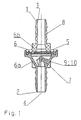
- Fig. 1 shows a schematic sectional view of the check valve according to the invention.
- This comprises a main body 1 with an inlet 2 and an outlet 3, which are fluidly connected to each other through a channel 4.
- a membrane 5 is arranged such that it releases the channel 4 exclusively in a flow direction.
- the main body 1 consists of two in the connecting region 6 complementary to each other formed sockets 7 and 8, which enclose the membrane 5 as a third part between them.
- the nozzle 7 and 8 and the membrane 5 are non-destructively releasably connected together.
- the nozzle 7 is the inlet 2 and the nozzle 8 of the outlet 1 assigned.
- the inlet 2, the outlet 3 and the channel 4 are arranged coaxially and colinearly.
- the nozzles 7, 8 have a cylindrical portion for receiving a hose connection and a connecting portion 6a, 6b for connection to another nozzle.
- the cylindrical sections for receiving a hose connection have circumferentially frusto-conical structures.
- the nozzle 7 has in the connecting portion 6 a stop 9, which is formed as an axially extending pin 10.
- the membrane 5 is designed such that it releases a circular channel 4.
- Fig. 2 shows an embodiment of the membrane 5.
- the membrane 5 comprises a circular ring 11 which surrounds an inner circle 12 and is connected to the circular ring 12 by a web 13.
- the annulus 11 acts as a seal and positioning element.
- the circular ring 11 is rectangular in cross section.
- the thickness and shape of the web 13 is designed to adjust the restoring force of the deflected circle 12.
- Fig. 3 shows a membrane, which tabs are associated with the realization of a defined deflection of the circle 12.
- the 4 shows a basic body 1 with a connecting piece 8, which is integrated in a Regnerierventil 14.
- the nozzle 7 connects with membrane 5.
- the regeneration valve 14 has an inlet 15 which is connectable to an activated carbon filter, not shown. This filters out hydrocarbons from gases that are in the tank of a motor vehicle.
- the regeneration valve 14 allows the defined supply of hydrocarbons from the activated carbon filter to the engine of the motor vehicle.
- the hydrocarbons flow through the inlet 15 to the nozzle 7.
- the nozzle 7 is connectable to a suction tube.
- the Regenerlervenfil 14 can be controlled by a motor controller and work electromagnetically.
Landscapes
- Engineering & Computer Science (AREA)
- General Engineering & Computer Science (AREA)
- Mechanical Engineering (AREA)
- Check Valves (AREA)
- Toys (AREA)
- Compressor (AREA)
- Valve-Gear Or Valve Arrangements (AREA)
Abstract
Description
- Die Erfindung betrifft ein Rückschlagventil, umfassend einen Grundkörper mit einem Einlass und einem Auslass, die durch einen Kanal miteinander strömungsverbindbar sind, wobei im Kanal eine Membran derart angeordnet ist, dass sie den Kanal ausschließlich in einer Strömungsrichtung freigibt. Die Erfindung betrifft des Weiteren eine Anordnung, welche ein Rückschlagventil und ein Regenerierventil umfasst.
- Rtickschiagvenfile der eingangs genannten Art sind aus dem Stand der Technik bereits bekannt. Diese sind häufig als Stopfen ausgestaltet, welchen auslassseitig eine Membran zugeordnet ist. Diese Stopfen sind als Einheit in eine nachgeordnete Anordnung einsetzbar. Bei dieser Ausgestaltung ist nachteilig, dass die Membran nach außen nahezu ungeschützt an der Auslassseite angeordnet ist. Insoweit ist die Membran Verschmutzungen und Beschädigungen schutzlos ausgesetzt, wenn das Rückschlagventil als Einzelteil transportiert oder montiert wird, Durch mechanische Beschädigungen oder Verunreinigungen der Membran ist deren einwandfreie Einsatzfähigkeit nicht mehr gewährleistet. Des Weiteren ist bei der Montage sicher zu stellen, dass die Membran korrekt im Gesamtsystem positioniert ist, um eine ausreichende Dichtheit desselben zu gewährleisten. Daher ist die Montage der bekannten Rückschlagventile ein äußerst aufwendiger Prozess.
- Der Erfindung liegt daher die Aufgabe zugrunde, ein System mit einem Rückschlagventil zu schaffen, welches eine einwandfreie Funktionsfähigkeit bei einfachem konstruktivem Aufbau und problemloser Montage gewährleistet.
- Erfindungsgemäß wird die voranstehende Aufgabe mit den Merkmalen des Patentanspruchs 1 gelöst.
- Danach ist ein Rückschlagventil der eingangs genannten Art dadurch gekennzeichnet, dass der Grundkörper aus zwei im Verbindungsbereich komplementär zueinander ausgebildeten Stutzen besteht, welche die Membran als drittes Teil zwischen sich einschließen,
- In efindungsgemäßer Weise ist zunächst erkannt worden, dass das gattungsbildende Rückschlagventil im Hinblick auf seine Verwendung in der Praxis erhebliche Nachteile aufweist. Des Weiteren ist erkannt worden, dass diese Nachteile damit zusammenhängen, dass die Membran frei zugänglich an der Auslassseite angeordnet ist Schließlich ist erkannt worden, dass die Membran in aufwendiger Weise positioniert werden muss, um eine Dichtheit des Gesamtsystems zu realisieren. Auf raffinierte Weise sind diese Nachteile des Standes der Technik dadurch überkommen worden, dass die Membran zwischen zwei geeignet komplementär ausgebildeten Teilen stets korrekt positioniert ist. Des Weiteren ist realisiert, dass die Teile einen Schutz der Membran bewerkstelligen, da sie diese zwischen sich einschließen und gegen Einflüsse der Umwelt abschirmen. Insoweit sind Beeinträchtigungen der Membran durch Verschmutzungen oder mechanische Beschädigungen nahezu ausgeschlossen. Folglich ist ein System mit einem Rückschlagventil angegeben, welches eine einwandfreie Funktionsfähigkeit bei einfachem konstruktivem Aufbau und problemloser Montage gewährleistet. Daher ist die eingangs genannte Aufgabe gelöst.
- In besonders vorteilhafter Weise könnten die Stutzen und die Membran zerstörungsfrei miteinander verbunden sein. Hierdurch ist realisierbar, dass eine Membran problemlos austauschbar ist. Dabei ist denkbar, dass die Stutzen miteinander verschraubt, aufeinander gesteckt oder über einen Bajonettverschluss verbunden sind.
- Eine nicht zerstörungsfreie Verbindung könnte durch Verkleben der Stutzen oder durch Ultraschallverschweißen der Stutzen erfolgen. Diese Form der Verbindung gewährleistet eine besondere Dichtheit an den Verbindungstellen.
- Einem Stutzen könnte der Einlass und dem anderen der Auslass zugeordnet sein, wobei der Einlass, der Auslass und der Kanal koaxial und kolinear angeordnet sind. Durch eine solche konstruktive Ausgestaltung des Rückschlagventils sind hohe Strömungsgeschwindigkeiten des das Rückschlagventil durchfließenden Strömungsmediums realisierbar, da das Strömungsmedium nicht umgelenkt wird. Vorteilhaft ist auch, dass das Vorhandensein der Membran durch Sichtkontrolle problemlos überprüfbar ist. Des Weiteren ermöglicht diese konkrete Ausgestaltung eines Rückschlagventils eine einfache Reinigung des Kanals durch einen geraden Gegenstand wie einen Stab oder Stift.
- Die Stutzen könnten einen zylindrischen Abschnitt zur Aufnahme einer Schlauchverbindung und einen Verbindungsabschnitt zur Verbindung mit einem anderen Stutzen aufweisen. Der zylindrische Abschnitt könnte profiliert ausgestaüet sein. Diese konkrete Ausgestaltung ermvglicht die Positionierung des Rückschlagventils in einer Schlauchleitung. Dabei ist denkbar, dass der Schlauch mittels einer Schlauchklemme sowohl am Auslass als auch am Einlass fest verbunden wird. Des Weiteren ist denkbar, dass der Auslass oder der Einlass einem Schlauch zugeordnet wird, wobei der Verbindungsabschnitt des Stutzens einer nachgeordneten Anordnung zugeordnet wird. Insoweit ist eine modulare Verwendung der einzelnen Stutzen realisierbar, wodurch das Rückschlagventil in unterschiedlichsten Einbausituationen Anwendung finden kann. Denkbar ist auch, den Stutzen nicht nur mit Schlauchleitungen sondem auch mit anderen Leitungen zu verbinden.
- Ein Stutzen könnte im Verbindungsabschnitt einen Anschlag zur Anlage der Membran aufweisen. Hierdurch ist realisierbar, dass die Membran einerseits in ihrer Position relativ zu den Stutzen fixierbar ist und andererseits im Hinblick auf ihr Aufklappverhalten innerhalb des Kanals einstellbar ist. Vor diesem Hintergrund ist beispielsweise denkbar, dass der Anschlag sich als axial erstreckender Stift ausgebildet ist, welcher durch seine Positionierung festlegt, wie weit die Membran in Strömungsrichtung aufklappbar ist. Je weiter der Stift von der Membran in geschlossenem Zustand entfernt ist, desto weiter kann die Membran aufgeklappt werden. Verzichtet man vollständig auf einen Stift so lässt sich die Membran parallel zur Achse des Kanals orientieren.
- Die Membran könnte derart angeordnet und/oder ausgebildet sein, dass sie einen kreisförmigen Kanal freigibt. Durch diese Ausgestaltung ist realisierbar, dass eine große Menge an Strömungsmedium die Membran passieren kann. Durch die Ausgestaltung eines kreisförmigen Kanals sind Verstopfungen nahezu ausgeschlossen, da Schwebeteilchen und Verunreinigungen eine kreisförmige Fläche problemlos passieren können.
- Die Membran könnte einen Kreisring umfassen, der einen inneren Kreis umgibt und mit dem Kreisring durch einen Steg verbunden ist. Diese konkrete Ausgestaltung erlaubt die Anlage des Kreisrings an den Stutzen, wodurch die Membran örtlich fixiert wird und wodurch die Membran an einer dem Stutzen zugeordneten Dichtkontur anlegbar ist. Die Vorkehrung eines inneren Kreises erlaubt die Realisierung eines kreisförmigen Kanals, der durch die Membran freigebbar ist. Der Steg fungiert als Gelenk, welches das Aufklappen des inneren Kreises in Strömungsrichtung realisiert.
- Der Kreisring könnte als Dichtring fungieren. Hierdurch ist realisierbar, dass die Membran zwei Räume gegeneinander oder einen Raum gegen die Atmosphäre abdichtet und das Strömungsmedium nur in Aufklapprichtung der Membran vom einen in den anderen Raum gelangen kann.
- Vor diesem Hintergrund ist denkbar, dass derKreisring im Querschnitt X-förmig ausgebildet ist. Des weiteren ist denkbar, dass der Kreisring im Querschnitt rechteckig ausgebildet ist oder als O-Ring ausgebildet ist. Ganz in Abhängigkeit von der Ausbildung der Stutzen, weiche komplementär zur Form des Kreisrings ausgebildet sind, ist eine Form des Kreisrings wählbar, welche eine sichere Fixierung der Membran bei maximaler Dichtigkeit realisiert. Hierbei stellt ein X-förmig ausgebildeter Kreisring eine besonders vorteilhafte Lösung dar, da die X-förmige Ausgestaltung eine Bewegung der Membran in axialer Richtung nahezu ausschließt. Dies hat seinen Grund darin, dass in den Stutzen ausgeformte Ausstülpungen in die Schenkel des X eingreifen können.
- Der innere Kreis der Membran könnte mit dem Kreisring durch Laschen wirkverbunden sein. Hierdurch ist realisierbar, dass das Aufklappverhalten des inneren Kreises beeinflussbar ist. Beispielsweise ist denkbar, dass die Laschen in ihrer Länge derart bemessen sind, dass sie nur einen bestimmten Öffnungswinkel des inneren Kreises zulassen.
- Die Membran könnte einen Kreis und einen mit diesem verbundenen Steg zur Anlage an einem Halteelement umfassen. Diese konkrete Ausgestaltung erlaubt eine einfache Fertigung der Membran wobei der Steg als Gelenk fungiert, welches das Aufklappen der Membran ermöglicht. Dabei ist denkbar, dass der Steg einen Durchgang aufweist, der beispielsweise auf einem Stift am Stutzen aufsteckbar ist. Zur Sicherung der Membran könnte auf diesen Stift ein Element aufgeschraubt, aufgeklebt oder aufgeschweißt werden, welches die Membran am Stutzen fixiert Denkbar ist auch, dass an beiden Stutzen jeweils ein Stift vorgesehen ist, welche im Zusammenspiel die Membran am Durchgang des Steges fixieren. Des Weiteren könnte eine Fixierung vorgesehen sein, welche eine Schwenkbewegung des Kreises um die Stiftachse verhindert und als Verdrehsicherung fungiert.
- Vor diesem Hintergrund könnte die Dicke des Steges zur Einstellung der Rückstellkraft des ausgelenkten Kreises ausgebildet sein. Diese Ausgestaltung ist dahingehend vorteilhaft, dass auf Federelemente oder andere die Rückstellung der Membran bewirkende Elemente weitgehend verzichtet werden kann. Durch die konkrete Ausgestaltung ist ein besonders kompakter und tellearmer Aufbau des Rückschlagventils realisierbar. Letztlich kann das gesamte Rückschlagventil aus drei Teilen bestehen, nämlich einem ersten und einem zweiten Stutzen sowie einer speziell ausgeformten Membran,
- Die Membran könnte durch geeignete Dickenverteilung des Steges unsymmetrisch aufklappbar sein. Beispielsweise ist denkbar, dass der Steg an einer Seite dicker als an einer anderen Seite ist und insoweit die Membran an einer Seite stärker am Aufklappen hindert als an einer anderen. Dies bewirkt ein verkipptes Aufklappen der Membran. Vor diesem Hintergund ist denkbar, dass die Dickenverteilung des Steges bzw. die Gesamtdicke des Steges auf die Drücke abgestimmt wird, bei denen das Rückschlagventil ansprechen soll. Bei der Verwendung des Rückschlagventils im Ansaugtrakt eines Motors oder in einem Regenerierventil können erhebliche Drücke auftreten. Die Dicke des Steges ist auf diese Drücke abstimmbar.
- Die Membran könnte aus Fluorsilikon gefertigt sein. Dieses konkrete Ausgestaltung realisiert eine Elastizität der Membran bei tiefen Temperaturen. Insoweit ist das Rückschlagventil auch an extreme Anforderungen anpassbar und kann beispielsweise in Kraftfahrzeugen und Motoren Verwendung finden.
- Die Membran könnte gewebeverstärkt ausgebildet sein, um eine besondere Steifigkeit aufzuweisen. Vor diesem Hintergrund ist denkbar, dass nicht nur die Membran gewebeverstärkt ausgebildet ist, sondern die Stutzen aus glasfasorgefülltem Kunststoff, insbesondere Polyamid 6.6, gefertigt sind. Diese konkrete Ausgestaltung des Rückschlagventils gewährleistet eine hohe Gebrauchstauglichkeit des Rückschlagventils im Hinblick auf dessen Verwendung in Kraftfahrzeugen.
- Die Membran könnte eine Antihaftbeschichtung aufweisen. Hierdurch ist realisierbar, dass nahezu keine Schwebe- oder Schmutzteilchen im Strömungsmedium an der Membran haften bleiben und insoweit zu Verstopfungen führen. Vorteilhaft ist auch, dass die Membran nicht am Stutzenmaterial anhaftet und daher ein reproduzierbares und definiertes Öffnungsverhalten zeigt.
- Einem Stutzen könnte ein Regenerierventil zugeordnet sein. Dies erlaubt die Verwendung des Rückschlagventils in einem System zur Zufuhr von Kohlenwasserstoffen aus Tankgasen zu einem Kraftfahrzeugmotor. Das Regenerierventil dosiert die Zugabe von Kohlenwasserstoffen, welche in einem Aktivkohlefilter aus Tankgasen herausgefiltert wurden.
- Vor diesem Hintergrund könnte der Stutzen in das Regenerierventil integriert sein, um einen besonders kompakten Aufbau zu realisieren, Insoweit ist eine einstückige Ausgestaltung des Regenerierventils mit einem ersten Stutzen realisiert, an welchen ein zweiter Stutzen mit Membran problemlos anfügbar ist. Dieser Aufbau ermöglicht die Schaffung eines Regenerierventils mit integriertem Rückschlagventil aus drei vorgefertigten Einzelteilen, wobei die Membran als einzige Dichtung zwischen den Stutzen fungiert.
- Das Regenerierventil könnte einen ersten Einlass aufweisen, welcher mit einem zweiten Einlass durch eine Motorsteuerung strömungsverbindbar ist. Dies ermöglicht eine gepulste Zufuhr von Strömungsmedien zu einer dem Rückschlagventil nachgeordneten Einrichtung, insbesondere einem Motor eines Kraftfahrzeugs.
- Des Weiteren ist die eingangs genannte Aufgabe durch eine Anordnung mit den Merkmalen des Patentanspruchs 25 gelöst. Um Wiederholungen zu vermeiden, sei in Bezug auf die erfinderische Tätigkeit auf die Ausführungen zum Rückschlagventil verwiesen.
- Es gibt nun verschiedene Möglichkeiten, die Lehre der vorliegenden Erfindung auf vorteilhafte Weise auszugestalten und weiterzubilden. Dazu ist einerseits auf die dem Patentanspruch 1 nachgeordneten Ansprüche, andererseits auf die nachfolgende Erläuterung bevorzugter Ausführungsbeispiele der Erfindung anhand der Zeichnung zu verweisen. In Verbindung mit der Erläuterung der bevorzugten Ausführungsbeispiele der Erfindung anhand der Zeichnung werden auch im Allgemeinen bevorzugte Ausgestaltungen und Weiterbildungen der Lehre erläutert.
- In der Zeichnung zeigen
- Fig. 1
- das erfindungsgemäße Rückschlagventil in einer schematischen Schnittansicht,
- Fig. 2
- die im Rückschlagventil gemäß Fig. 1 verwendete Membran,
- Fig. 3
- eine Membran, welche Laschen aufweist, und
- Fig. 4
- ein Rückschlagventil, welchem ein Regenerierventil zugeordnet ist.
- Fig. 1 zeigt in einer schematischen Schnittansicht das erfindungsgemäße Rückschlagventil. Dieses umfasst einen Grundkörper 1 mit einem Einlass 2 und einem Auslass 3, die durch einen Kanal 4 miteinander strömungsverbindbar sind. Im Kanal 4 ist eine Membran 5 derart angeordnet, dass sie den Kanal 4 ausschließlich in einer Strömungsrichtung freigibt. Der Grundkörper 1 besteht aus zwei im Verbindungsbereich 6 komplementär zueinander ausgebildeten Stutzen 7 und 8, weiche die Membran 5 als drittes Teil zwischen sich einschließen.
- Die Stutzen 7 und 8 sowie die Membran 5 sind zerstörungsfrei lösbar miteinander verbunden. Dem Stutzen 7 ist der Einlass 2 und dem Stutzen 8 der Auslass 1 zugeordnet. Der Einlass 2, der Auslass 3 sowie der Kanal 4 sind koaxial und kolinear angeordnet.
- Die Stutzen 7, 8 weisen einen zylindrischen Abschnitt zur Aufnahme einer Schlauchverbindung und einen Verbindungsabschnitt 6a, 6b zur Verbindung mit einem anderen Stutzen auf. Die zylindrischen Abschnitte zur Aufnahme einer Schlauchverbindung weisen umfänglich kegelstumpfartige Strukturen auf.
- Der Stutzen 7 weist im Verbindungsabschnitt 6 einen Anschlag 9 auf, der als sich axial erstreckender Stift 10 ausgebildet ist. Die Membran 5 ist derart ausgebildet, dass sie einen kreisförmigen Kanal 4 freigibt.
- Fig. 2 zeigt eine Ausführungsform der Membran 5. Die Membran 5 umfasst einen Kreisring 11, der einen inneren Kreis 12 umgibt und mit dem Kreisring 12 durch einen Steg 13 verbunden ist.
- Der Kreisring 11 fungiert als Dichtung und Positionierungsetement. Der Kreisring 11 ist im Querschnitt rechteckig ausgebildet. Die Dicke und Form des Steges 13 ist zur Einstellung der Rückstellkraft des ausgelenkten Kreises 12 ausgebildet.
- Fig. 3 zeigt eine Membran, welcher Laschen zur Realisierung einer definierten Auslenkung des Kreises 12 zugeordnet sind.
- Fig. 4 zeigt einen Grundkörper 1 mit einem Stutzen 8, welcher in ein Regnerierventil 14 integriert ist. An den Stutzen 8 schließt sich der Stutzen 7 mit Membran 5 an. Das Regenerierventil 14 weist einen Einlass 15 auf, der mit einem nicht gezeigten Aktivkohlefilter verbindbar ist. Dieser filtert Kohlenwasserstoffe aus Gasen heraus, welche sich im Tank eines Kraftfahrzeugs befinden. Das Regenerierventil 14 erlaubt die definierte Zufuhr von Kohlenwasserstoffen aus dem Aktivkohlefilter zum Motor des Kraftfahrzeugs. Die Kohlenwasserstoffe strömen durch den Einlass 15 zum Stutzen 7. Der Stutzen 7 ist mit einem Saugrohr verbindbar. Das Regenerlervenfil 14 kann durch eine Motorsteuerung angesteuert werden und elektromagnetisch arbeiten.
- Hinsichtlich weiterer vorteilhafter Ausgestaltungen und Weiterbildungen der erfindungsgemäßen Lehre wird einerseits auf den allgemeinen Teil der Beschreibung und andererseits auf die beigefügten Patentansprüche verwiesen. Abschließend sei ganz besonders hervorgehoben, dass die zuvor rein willkürlich gewählten Ausführungsbeispiele lediglich zur Erörterung der erfindungsgemäßen Lehre dienen, diese jedoch nicht auf diese Ausführungsbeispiele einschränken.
Claims (25)
- Rückschlagventil, umfassend einen Grundkörper (1) mit einem Einlass (2) und einem Auslass (3), die durch einen Kanal (4) miteinander strömungsverbindbar sind, wobei im Kanal (4) eine Membran (5) derart angeordnet ist, dass sie den Kanal (4) ausschließlich in einer Strömungsrichtung freigibt,
dadurch gekennzeichnet, dass der Grundkörper (1) aus zwei im Verbindungsbereich (6) komplementär zueinander ausgebildeten Stutzen (7, 8) besteht, welche die Membran (5) als drittes Teil zwischen sich einschließen. - Rückschlagventil nach Anspruch 1, dadurch gekennzeichnet, dass die Stutzen (7, 8) und die Membran (5) zerstörungsfrei lösbar miteinander verbunden sind.
- Rückschlagventil nach Anspruch 1, dadurch gekennzeichnet, dass die Stutzen (7, 8) und die Membran (5) fest miteinander verbunden sind.
- Rückschlagventil nach einem der Ansprüche 1 bis 3, dadurch gekennzeichnet, dass einem Stutzen (7) der Einlass (2) und dem anderen der Auslass (3) zugeordnet ist und der Einlass (2), der Auslass (3) und der Kanal (4) koaxial und kolinear angeordnet sind.
- Rückschlagventil nach einem der Ansprüche 1 bis 4. dadurch gekennzeichnet, dass mindestens ein Stutzen (7, 8) einen zylindrischen Abschnitt zur Aufnahme einer Schlauchverbindung und einen Verbindungsabschnitt (6a, 6b) zur Verbindung mit einem anderen Stutzen (7, 8) aufweist.
- Rückschlagventil nach einem der Ansprüche 1 bis 5, dadurch gekennzeichnet, dass mindestens ein Stutzen (7) im Verbindungsabschnitt einen Anschlag (9) zur Anlage der Membran (5) aufweist.
- Rückschlagventil nach Anspruch 6, dadurch gekennzeichnet, dass der Anschlag (9) als sich axial erstreckender Stift (10) ausgebildet ist.
- Rückschlagventil nach einem der Ansprüche 1 bis 7, dadurch gekennzeichnet, dass die Membran (5) derart angeordnet und/ oder ausgebildet ist, dass sie einen kreisförmigen Kanal (4) freigibt.
- Rückschlagventil nach einem der Ansprüche 1 bis 8, dadurch gekennzeichnet, dass die Membran (5) einen Kreisring (11) umfasst, der einen inneren Kreis (12) umgibt und mit dem Kreisring (11) durch einen Steg (13) verbunden ist.
- Rückschlagventil nach Anspruch 9, dadurch gekennzeichnet, dass der Kreisring (11) als Dichtring fungiert.
- Rückschlagventil nach Anspruch 10, dadurch gekennzeichnet, dass der Kreisring (11) als Positionierungselement fungiert.
- Rückschlagventil nach einem der Ansprüche 9 bis 11, dadurch gekennzeichnet, dass der Kreisring (11) im Querschnitt X-förmig ausgebildet ist.
- Rückschlagventil nach einem der Ansprüche 9 bis 11, dadurch gekennzeichnet, dass der Kreisring (11) im Querschnitt rechteckig ausgebildet ist.
- Rückschlagventil nach einem der Ansprüche 9 bis 11, dadurch gekennzeichnet, dass der Kreisring (11) als O-Ring ausgebildet ist.
- Rückschlagventil nach einem der Ansprüche 9 bis 14, dadurch gekennzeichnet, dass der innere Kreis (12) mit dem Kreisring (11) durch Laschen wirkverbunden ist.
- Rückschlagventil nach einem der Ansprüche 1 bis 8, dadurch gekennzeichnet, dass die Membran (5) einen Kreis (12) und einen mit diesem verbundenen Steg (13) zur Anlage an einem Halteelement umfasst.
- Rückschlagventil nach einem der Ansprüche 9 bis 16, dadurch gekennzeichnet, dass die Dicke des Steges (13) zur Einstellung der Rückstellkraft des ausgelenkten Kreises (12) ausgebildet ist.
- Rückschlagventil nach einem der Ansprüche 9 bis 17, dadurch gekennzeichnet, dass die Membran (5) durch geeignete Dickenverteilung des Steges (13) unsymmetrisch aufklappbar ist.
- Rückschlagventil nach einem der Ansprüche 1 bis 18, dadurch gekennzeichnet, dass die Membran (5) aus Fluorsilikon gefertigt ist.
- Rückschlagventil nach einem der Ansprüche 1 bis 19, dadurch gekennzeichnet, dass die Membran (5) gewebeverstärkt ausgebildet ist.
- Rückschlagventil nach einem der Ansprüche 1 bis 20, dadurch gekennzeichnet, dass die Membran (5) eine Antihaftbeschichtung aufweist.
- Rückschlagventil nach einem der Ansprüche 1 bis 21, dadurch gekennzeichnet, dass dem Stutzen (8) ein Regenerierventil (14) zugeordnet ist.
- Rückschlagventil nach Anspruch 22, dadurch gekennzeichnet, dass der Stutzen (8) in das Regenerierventil (14) integriert ist.
- Rückschlagventil nach Anspruch 23, dadurch gekennzeichnet, dass das Regenerlerventil (14) einen Einlass (15) aufweist, welcher mit dem Einlass (2) durch eine Motorsteuerung strömungsverbindbar ist.
- Anordnung mit einem Regenerierventil und einem Rückschlagventil nach einem der Ansprüche 1 bis 24.
Priority Applications (3)
| Application Number | Priority Date | Filing Date | Title |
|---|---|---|---|
| DE502005001013T DE502005001013D1 (de) | 2005-03-18 | 2005-03-18 | Rückschlagventil |
| EP05005981A EP1703183B1 (de) | 2005-03-18 | 2005-03-18 | Rückschlagventil |
| AT05005981T ATE366886T1 (de) | 2005-03-18 | 2005-03-18 | Rückschlagventil |
Applications Claiming Priority (1)
| Application Number | Priority Date | Filing Date | Title |
|---|---|---|---|
| EP05005981A EP1703183B1 (de) | 2005-03-18 | 2005-03-18 | Rückschlagventil |
Publications (2)
| Publication Number | Publication Date |
|---|---|
| EP1703183A1 true EP1703183A1 (de) | 2006-09-20 |
| EP1703183B1 EP1703183B1 (de) | 2007-07-11 |
Family
ID=34934359
Family Applications (1)
| Application Number | Title | Priority Date | Filing Date |
|---|---|---|---|
| EP05005981A Expired - Lifetime EP1703183B1 (de) | 2005-03-18 | 2005-03-18 | Rückschlagventil |
Country Status (3)
| Country | Link |
|---|---|
| EP (1) | EP1703183B1 (de) |
| AT (1) | ATE366886T1 (de) |
| DE (1) | DE502005001013D1 (de) |
Cited By (4)
| Publication number | Priority date | Publication date | Assignee | Title |
|---|---|---|---|---|
| EP1918620A3 (de) * | 2006-10-30 | 2008-08-13 | Filtertek B.V. | Rückschlagventil, insbesondere für medizinische Anwendungen |
| WO2009021605A1 (de) * | 2007-08-13 | 2009-02-19 | Filtertek B.V. | Rückschlagventil, insbesondere für medizinische anwendungen |
| CN103195616A (zh) * | 2013-04-24 | 2013-07-10 | 河北亚大汽车塑料制品有限公司 | 一种燃油蒸汽单向阀 |
| US11662034B2 (en) | 2019-07-24 | 2023-05-30 | Quest Medical, Inc. | Filtered vacuum relief vent valve |
Citations (7)
| Publication number | Priority date | Publication date | Assignee | Title |
|---|---|---|---|---|
| US5025829A (en) * | 1990-01-29 | 1991-06-25 | Harmac Medical Products, Inc. | Parenteral check valve |
| EP0582038A2 (de) * | 1992-08-07 | 1994-02-09 | B. Braun Melsungen AG | Schutzvorrichtung für einen Belüftungskanal eines Flüssigkeitsüberleitungsgerätes |
| EP0612537A2 (de) * | 1993-02-18 | 1994-08-31 | Filtertek, S.A. | Rückschlagventil, insbesondere für medizinische Anwendungen der Fluidtechnik |
| EP0638328A1 (de) * | 1993-07-14 | 1995-02-15 | B. Braun Melsungen Ag | Rückschlagventil |
| DE4439881C1 (de) * | 1994-11-08 | 1996-02-22 | Freudenberg Carl Fa | Vorrichtung zum vorübergehenden Speichern und dosierten Einspeisen der im Freiraum einer Tankanlage befindlichen flüchtigen Kraftstoffbestandteile in das Ansaugrohr einer mit einem Lader versehenen und durch diesen aufladbaren Verbrennungskraftmaschine |
| US5809977A (en) * | 1995-05-05 | 1998-09-22 | Robert Bosch Gmbh | Valve for metered introduction of volatilized fuel |
| US20030188790A1 (en) * | 2002-04-08 | 2003-10-09 | J. Schmalz Gmbh | Underpressure valve |
-
2005
- 2005-03-18 EP EP05005981A patent/EP1703183B1/de not_active Expired - Lifetime
- 2005-03-18 AT AT05005981T patent/ATE366886T1/de not_active IP Right Cessation
- 2005-03-18 DE DE502005001013T patent/DE502005001013D1/de not_active Expired - Lifetime
Patent Citations (7)
| Publication number | Priority date | Publication date | Assignee | Title |
|---|---|---|---|---|
| US5025829A (en) * | 1990-01-29 | 1991-06-25 | Harmac Medical Products, Inc. | Parenteral check valve |
| EP0582038A2 (de) * | 1992-08-07 | 1994-02-09 | B. Braun Melsungen AG | Schutzvorrichtung für einen Belüftungskanal eines Flüssigkeitsüberleitungsgerätes |
| EP0612537A2 (de) * | 1993-02-18 | 1994-08-31 | Filtertek, S.A. | Rückschlagventil, insbesondere für medizinische Anwendungen der Fluidtechnik |
| EP0638328A1 (de) * | 1993-07-14 | 1995-02-15 | B. Braun Melsungen Ag | Rückschlagventil |
| DE4439881C1 (de) * | 1994-11-08 | 1996-02-22 | Freudenberg Carl Fa | Vorrichtung zum vorübergehenden Speichern und dosierten Einspeisen der im Freiraum einer Tankanlage befindlichen flüchtigen Kraftstoffbestandteile in das Ansaugrohr einer mit einem Lader versehenen und durch diesen aufladbaren Verbrennungskraftmaschine |
| US5809977A (en) * | 1995-05-05 | 1998-09-22 | Robert Bosch Gmbh | Valve for metered introduction of volatilized fuel |
| US20030188790A1 (en) * | 2002-04-08 | 2003-10-09 | J. Schmalz Gmbh | Underpressure valve |
Cited By (6)
| Publication number | Priority date | Publication date | Assignee | Title |
|---|---|---|---|---|
| EP1918620A3 (de) * | 2006-10-30 | 2008-08-13 | Filtertek B.V. | Rückschlagventil, insbesondere für medizinische Anwendungen |
| WO2009021605A1 (de) * | 2007-08-13 | 2009-02-19 | Filtertek B.V. | Rückschlagventil, insbesondere für medizinische anwendungen |
| US8291936B2 (en) | 2007-08-13 | 2012-10-23 | Illinois Tool Works Inc. | Non-return valve, in particular for medical uses |
| CN103195616A (zh) * | 2013-04-24 | 2013-07-10 | 河北亚大汽车塑料制品有限公司 | 一种燃油蒸汽单向阀 |
| CN103195616B (zh) * | 2013-04-24 | 2016-04-13 | 河北亚大汽车塑料制品有限公司 | 一种燃油蒸汽单向阀 |
| US11662034B2 (en) | 2019-07-24 | 2023-05-30 | Quest Medical, Inc. | Filtered vacuum relief vent valve |
Also Published As
| Publication number | Publication date |
|---|---|
| EP1703183B1 (de) | 2007-07-11 |
| ATE366886T1 (de) | 2007-08-15 |
| DE502005001013D1 (de) | 2007-08-23 |
Similar Documents
| Publication | Publication Date | Title |
|---|---|---|
| EP2054133B1 (de) | Flüssigkeitsfilter, insbesondere für kraftfahrzeuge | |
| EP2399019B1 (de) | Wasserabscheider, insbesondere für kraftstoffzuführsysteme von brennkraftmaschinen in kraftfahrzeugen | |
| EP2226107A1 (de) | Wasserabscheider insbesondere für Kraftstoffzuführsysteme von Brennkraftmaschinen in Kraftfahrzeugen | |
| DE112007003263T5 (de) | Durchsatzsteuervorrichtung | |
| DE3843659A1 (de) | Anschlussvorrichtung fuer einspritzduesen | |
| DE3941236A1 (de) | Anschluss-rohrleitung und rohrleitungsbuendel | |
| WO2021078808A1 (de) | Behandlungsvorrichtung zur behandlung von insbesondere flüssigen fluiden sowie behandlungseinheit und anschlusskopf für eine behandlungsvorrichtung | |
| WO2021078759A1 (de) | Behandlungsvorrichtung zur behandlung von insbesondere flüssigen fluiden sowie behandlungseinheit und anschlusskopf für eine behandlungsvorrichtung | |
| EP1703183B1 (de) | Rückschlagventil | |
| EP1728541B1 (de) | Filterelement für einen Flüssigkeitsfilter | |
| WO1997027417A1 (de) | Rohrverbinder | |
| DE19533920A1 (de) | Vorrichtung zum lösbaren Verbinden der Enden eines Verbindungsschlauches mit jeweils einem Bauteil aus Kunststoff | |
| WO2013023828A1 (de) | Ansatzstutzen für filterschläuche | |
| DE102012107263B4 (de) | Steckvorrichtung in einem Endbereich einer Leitung und Verfahren zur Herstellung einer Steckvorrichtung | |
| EP3414436A1 (de) | Abgasauslasssystem für ein kraftfahrzeug, kraftfahrzeug mit einem solchen abgasauslasssystem sowie verfahren zur herstellung eines abgasauslasssystems | |
| DE102015016237A1 (de) | Filterbalg und Filterelement | |
| EP1231377A2 (de) | Filter für Flüssigkeiten, insbesondere Kraftstoffe | |
| DE3627393C1 (en) | Connection part for joining a water meter to a T-shaped pipe connection | |
| DE102004005210A1 (de) | Filter, insbesondere Kraftfahrzeug-Ansaugfilter | |
| DE102015006713A1 (de) | Verspannvorrichtung zur Verspannung eines Fluidfilterelementes, insbesondere Luftfilterelementes in einem Filtergehäuse und Fluidfilter | |
| DE102016213006A1 (de) | Einrichtung zur Geräuschverringerung für eine Unterdruckleitung eines Bremskraftverstärkers | |
| DE102024102387B4 (de) | Fluidverbindungssystem | |
| DE102009047957A1 (de) | Vorrichtung zum Verbinden von zwei Bauteilen | |
| DE102013020652A1 (de) | Sanitärarmatur mit Anschlussadapter | |
| DE102012109033B4 (de) | Anschlussvorrichtung |
Legal Events
| Date | Code | Title | Description |
|---|---|---|---|
| PUAI | Public reference made under article 153(3) epc to a published international application that has entered the european phase |
Free format text: ORIGINAL CODE: 0009012 |
|
| 17P | Request for examination filed |
Effective date: 20051209 |
|
| AK | Designated contracting states |
Kind code of ref document: A1 Designated state(s): AT BE BG CH CY CZ DE DK EE ES FI FR GB GR HU IE IS IT LI LT LU MC NL PL PT RO SE SI SK TR |
|
| AX | Request for extension of the european patent |
Extension state: AL BA HR LV MK YU |
|
| GRAP | Despatch of communication of intention to grant a patent |
Free format text: ORIGINAL CODE: EPIDOSNIGR1 |
|
| GRAS | Grant fee paid |
Free format text: ORIGINAL CODE: EPIDOSNIGR3 |
|
| AKX | Designation fees paid |
Designated state(s): AT BE BG CH CY CZ DE DK EE ES FI FR GB GR HU IE IS IT LI LT LU MC NL PL PT RO SE SI SK TR |
|
| GRAA | (expected) grant |
Free format text: ORIGINAL CODE: 0009210 |
|
| AK | Designated contracting states |
Kind code of ref document: B1 Designated state(s): AT BE BG CH CY CZ DE DK EE ES FI FR GB GR HU IE IS IT LI LT LU MC NL PL PT RO SE SI SK TR |
|
| REG | Reference to a national code |
Ref country code: GB Ref legal event code: FG4D Free format text: NOT ENGLISH |
|
| REG | Reference to a national code |
Ref country code: CH Ref legal event code: EP |
|
| REF | Corresponds to: |
Ref document number: 502005001013 Country of ref document: DE Date of ref document: 20070823 Kind code of ref document: P |
|
| REG | Reference to a national code |
Ref country code: IE Ref legal event code: FG4D Free format text: LANGUAGE OF EP DOCUMENT: GERMAN |
|
| ET | Fr: translation filed | ||
| PG25 | Lapsed in a contracting state [announced via postgrant information from national office to epo] |
Ref country code: PT Free format text: LAPSE BECAUSE OF FAILURE TO SUBMIT A TRANSLATION OF THE DESCRIPTION OR TO PAY THE FEE WITHIN THE PRESCRIBED TIME-LIMIT Effective date: 20071211 Ref country code: ES Free format text: LAPSE BECAUSE OF FAILURE TO SUBMIT A TRANSLATION OF THE DESCRIPTION OR TO PAY THE FEE WITHIN THE PRESCRIBED TIME-LIMIT Effective date: 20071022 Ref country code: BG Free format text: LAPSE BECAUSE OF FAILURE TO SUBMIT A TRANSLATION OF THE DESCRIPTION OR TO PAY THE FEE WITHIN THE PRESCRIBED TIME-LIMIT Effective date: 20071011 Ref country code: FI Free format text: LAPSE BECAUSE OF FAILURE TO SUBMIT A TRANSLATION OF THE DESCRIPTION OR TO PAY THE FEE WITHIN THE PRESCRIBED TIME-LIMIT Effective date: 20070711 Ref country code: IS Free format text: LAPSE BECAUSE OF FAILURE TO SUBMIT A TRANSLATION OF THE DESCRIPTION OR TO PAY THE FEE WITHIN THE PRESCRIBED TIME-LIMIT Effective date: 20071111 Ref country code: NL Free format text: LAPSE BECAUSE OF FAILURE TO SUBMIT A TRANSLATION OF THE DESCRIPTION OR TO PAY THE FEE WITHIN THE PRESCRIBED TIME-LIMIT Effective date: 20070711 Ref country code: LT Free format text: LAPSE BECAUSE OF FAILURE TO SUBMIT A TRANSLATION OF THE DESCRIPTION OR TO PAY THE FEE WITHIN THE PRESCRIBED TIME-LIMIT Effective date: 20070711 |
|
| NLV1 | Nl: lapsed or annulled due to failure to fulfill the requirements of art. 29p and 29m of the patents act | ||
| GBV | Gb: ep patent (uk) treated as always having been void in accordance with gb section 77(7)/1977 [no translation filed] |
Effective date: 20070711 |
|
| PG25 | Lapsed in a contracting state [announced via postgrant information from national office to epo] |
Ref country code: PL Free format text: LAPSE BECAUSE OF FAILURE TO SUBMIT A TRANSLATION OF THE DESCRIPTION OR TO PAY THE FEE WITHIN THE PRESCRIBED TIME-LIMIT Effective date: 20070711 |
|
| REG | Reference to a national code |
Ref country code: IE Ref legal event code: FD4D |
|
| PG25 | Lapsed in a contracting state [announced via postgrant information from national office to epo] |
Ref country code: GR Free format text: LAPSE BECAUSE OF FAILURE TO SUBMIT A TRANSLATION OF THE DESCRIPTION OR TO PAY THE FEE WITHIN THE PRESCRIBED TIME-LIMIT Effective date: 20071012 Ref country code: DK Free format text: LAPSE BECAUSE OF FAILURE TO SUBMIT A TRANSLATION OF THE DESCRIPTION OR TO PAY THE FEE WITHIN THE PRESCRIBED TIME-LIMIT Effective date: 20070711 |
|
| PLBE | No opposition filed within time limit |
Free format text: ORIGINAL CODE: 0009261 |
|
| STAA | Information on the status of an ep patent application or granted ep patent |
Free format text: STATUS: NO OPPOSITION FILED WITHIN TIME LIMIT |
|
| PG25 | Lapsed in a contracting state [announced via postgrant information from national office to epo] |
Ref country code: GB Free format text: LAPSE BECAUSE OF FAILURE TO SUBMIT A TRANSLATION OF THE DESCRIPTION OR TO PAY THE FEE WITHIN THE PRESCRIBED TIME-LIMIT Effective date: 20070711 Ref country code: IE Free format text: LAPSE BECAUSE OF FAILURE TO SUBMIT A TRANSLATION OF THE DESCRIPTION OR TO PAY THE FEE WITHIN THE PRESCRIBED TIME-LIMIT Effective date: 20070711 Ref country code: SK Free format text: LAPSE BECAUSE OF FAILURE TO SUBMIT A TRANSLATION OF THE DESCRIPTION OR TO PAY THE FEE WITHIN THE PRESCRIBED TIME-LIMIT Effective date: 20070711 Ref country code: CZ Free format text: LAPSE BECAUSE OF FAILURE TO SUBMIT A TRANSLATION OF THE DESCRIPTION OR TO PAY THE FEE WITHIN THE PRESCRIBED TIME-LIMIT Effective date: 20070711 |
|
| 26N | No opposition filed |
Effective date: 20080414 |
|
| PG25 | Lapsed in a contracting state [announced via postgrant information from national office to epo] |
Ref country code: SE Free format text: LAPSE BECAUSE OF FAILURE TO SUBMIT A TRANSLATION OF THE DESCRIPTION OR TO PAY THE FEE WITHIN THE PRESCRIBED TIME-LIMIT Effective date: 20071011 Ref country code: RO Free format text: LAPSE BECAUSE OF FAILURE TO SUBMIT A TRANSLATION OF THE DESCRIPTION OR TO PAY THE FEE WITHIN THE PRESCRIBED TIME-LIMIT Effective date: 20070711 |
|
| BERE | Be: lapsed |
Owner name: CARL FREUDENBERG K.G. Effective date: 20080331 |
|
| PG25 | Lapsed in a contracting state [announced via postgrant information from national office to epo] |
Ref country code: MC Free format text: LAPSE BECAUSE OF NON-PAYMENT OF DUE FEES Effective date: 20080331 |
|
| PG25 | Lapsed in a contracting state [announced via postgrant information from national office to epo] |
Ref country code: EE Free format text: LAPSE BECAUSE OF FAILURE TO SUBMIT A TRANSLATION OF THE DESCRIPTION OR TO PAY THE FEE WITHIN THE PRESCRIBED TIME-LIMIT Effective date: 20070711 |
|
| PG25 | Lapsed in a contracting state [announced via postgrant information from national office to epo] |
Ref country code: BE Free format text: LAPSE BECAUSE OF NON-PAYMENT OF DUE FEES Effective date: 20080331 |
|
| PG25 | Lapsed in a contracting state [announced via postgrant information from national office to epo] |
Ref country code: SI Free format text: LAPSE BECAUSE OF FAILURE TO SUBMIT A TRANSLATION OF THE DESCRIPTION OR TO PAY THE FEE WITHIN THE PRESCRIBED TIME-LIMIT Effective date: 20070711 |
|
| PG25 | Lapsed in a contracting state [announced via postgrant information from national office to epo] |
Ref country code: CY Free format text: LAPSE BECAUSE OF FAILURE TO SUBMIT A TRANSLATION OF THE DESCRIPTION OR TO PAY THE FEE WITHIN THE PRESCRIBED TIME-LIMIT Effective date: 20070711 |
|
| PG25 | Lapsed in a contracting state [announced via postgrant information from national office to epo] |
Ref country code: AT Free format text: LAPSE BECAUSE OF NON-PAYMENT OF DUE FEES Effective date: 20080318 |
|
| REG | Reference to a national code |
Ref country code: CH Ref legal event code: PL |
|
| PG25 | Lapsed in a contracting state [announced via postgrant information from national office to epo] |
Ref country code: LI Free format text: LAPSE BECAUSE OF NON-PAYMENT OF DUE FEES Effective date: 20090331 Ref country code: CH Free format text: LAPSE BECAUSE OF NON-PAYMENT OF DUE FEES Effective date: 20090331 |
|
| PG25 | Lapsed in a contracting state [announced via postgrant information from national office to epo] |
Ref country code: HU Free format text: LAPSE BECAUSE OF FAILURE TO SUBMIT A TRANSLATION OF THE DESCRIPTION OR TO PAY THE FEE WITHIN THE PRESCRIBED TIME-LIMIT Effective date: 20080112 Ref country code: LU Free format text: LAPSE BECAUSE OF NON-PAYMENT OF DUE FEES Effective date: 20080318 |
|
| PG25 | Lapsed in a contracting state [announced via postgrant information from national office to epo] |
Ref country code: TR Free format text: LAPSE BECAUSE OF FAILURE TO SUBMIT A TRANSLATION OF THE DESCRIPTION OR TO PAY THE FEE WITHIN THE PRESCRIBED TIME-LIMIT Effective date: 20070711 |
|
| REG | Reference to a national code |
Ref country code: DE Ref legal event code: R081 Ref document number: 502005001013 Country of ref document: DE Owner name: EAGLE ACTUATOR COMPONENTS GMBH & CO. KG, DE Free format text: FORMER OWNER: ACTUATOR COMPONENTS GMBH & CO. KG, 69469 WEINHEIM, DE Effective date: 20120330 Ref country code: DE Ref legal event code: R081 Ref document number: 502005001013 Country of ref document: DE Owner name: EAGLE ACTUATOR COMPONENTS GMBH & CO. KG, DE Free format text: FORMER OWNER: CARL FREUDENBERG KG, 69469 WEINHEIM, DE Effective date: 20120308 |
|
| REG | Reference to a national code |
Ref country code: FR Ref legal event code: TP Owner name: EAGLE ACTUATOR COMPONENTS GMBH & CO.KG, DE Effective date: 20120417 |
|
| REG | Reference to a national code |
Ref country code: FR Ref legal event code: PLFP Year of fee payment: 12 |
|
| REG | Reference to a national code |
Ref country code: DE Ref legal event code: R082 Ref document number: 502005001013 Country of ref document: DE Representative=s name: REBLE KLOSE SCHMITT PARTNERSCHAFTSGESELLSCHAFT, DE |
|
| REG | Reference to a national code |
Ref country code: FR Ref legal event code: PLFP Year of fee payment: 13 |
|
| REG | Reference to a national code |
Ref country code: FR Ref legal event code: PLFP Year of fee payment: 14 |
|
| REG | Reference to a national code |
Ref country code: DE Ref legal event code: R081 Ref document number: 502005001013 Country of ref document: DE Owner name: EAGLE ACTUATOR COMPONENTS GMBH & CO. KG, DE Free format text: FORMER OWNER: EAGLE ACTUATOR COMPONENTS GMBH & CO. KG, 69469 WEINHEIM, DE |
|
| PGFP | Annual fee paid to national office [announced via postgrant information from national office to epo] |
Ref country code: DE Payment date: 20240321 Year of fee payment: 20 |
|
| PGFP | Annual fee paid to national office [announced via postgrant information from national office to epo] |
Ref country code: IT Payment date: 20240329 Year of fee payment: 20 Ref country code: FR Payment date: 20240320 Year of fee payment: 20 |
|
| REG | Reference to a national code |
Ref country code: DE Ref legal event code: R071 Ref document number: 502005001013 Country of ref document: DE |