EP1703105A1 - Système d'aide à la régénération d'un piège à NOx intégré dans une ligne d'échappement d'un moteur de véhicule automobile - Google Patents
Système d'aide à la régénération d'un piège à NOx intégré dans une ligne d'échappement d'un moteur de véhicule automobile Download PDFInfo
- Publication number
- EP1703105A1 EP1703105A1 EP05292488A EP05292488A EP1703105A1 EP 1703105 A1 EP1703105 A1 EP 1703105A1 EP 05292488 A EP05292488 A EP 05292488A EP 05292488 A EP05292488 A EP 05292488A EP 1703105 A1 EP1703105 A1 EP 1703105A1
- Authority
- EP
- European Patent Office
- Prior art keywords
- fuel
- engine
- injected
- injection
- cylinder
- Prior art date
- Legal status (The legal status is an assumption and is not a legal conclusion. Google has not performed a legal analysis and makes no representation as to the accuracy of the status listed.)
- Granted
Links
Images


Classifications
-
- F—MECHANICAL ENGINEERING; LIGHTING; HEATING; WEAPONS; BLASTING
- F01—MACHINES OR ENGINES IN GENERAL; ENGINE PLANTS IN GENERAL; STEAM ENGINES
- F01N—GAS-FLOW SILENCERS OR EXHAUST APPARATUS FOR MACHINES OR ENGINES IN GENERAL; GAS-FLOW SILENCERS OR EXHAUST APPARATUS FOR INTERNAL-COMBUSTION ENGINES
- F01N3/00—Exhaust or silencing apparatus having means for purifying, rendering innocuous, or otherwise treating exhaust
- F01N3/08—Exhaust or silencing apparatus having means for purifying, rendering innocuous, or otherwise treating exhaust for rendering innocuous
- F01N3/0807—Exhaust or silencing apparatus having means for purifying, rendering innocuous, or otherwise treating exhaust for rendering innocuous by using absorbents or adsorbents
- F01N3/0828—Exhaust or silencing apparatus having means for purifying, rendering innocuous, or otherwise treating exhaust for rendering innocuous by using absorbents or adsorbents characterised by the absorbed or adsorbed substances
- F01N3/0842—Nitrogen oxides
-
- F—MECHANICAL ENGINEERING; LIGHTING; HEATING; WEAPONS; BLASTING
- F01—MACHINES OR ENGINES IN GENERAL; ENGINE PLANTS IN GENERAL; STEAM ENGINES
- F01N—GAS-FLOW SILENCERS OR EXHAUST APPARATUS FOR MACHINES OR ENGINES IN GENERAL; GAS-FLOW SILENCERS OR EXHAUST APPARATUS FOR INTERNAL-COMBUSTION ENGINES
- F01N3/00—Exhaust or silencing apparatus having means for purifying, rendering innocuous, or otherwise treating exhaust
- F01N3/08—Exhaust or silencing apparatus having means for purifying, rendering innocuous, or otherwise treating exhaust for rendering innocuous
- F01N3/0807—Exhaust or silencing apparatus having means for purifying, rendering innocuous, or otherwise treating exhaust for rendering innocuous by using absorbents or adsorbents
- F01N3/0871—Exhaust or silencing apparatus having means for purifying, rendering innocuous, or otherwise treating exhaust for rendering innocuous by using absorbents or adsorbents using means for controlling, e.g. purging, the absorbents or adsorbents
- F01N3/0885—Regeneration of deteriorated absorbents or adsorbents, e.g. desulfurization of NOx traps
-
- F—MECHANICAL ENGINEERING; LIGHTING; HEATING; WEAPONS; BLASTING
- F02—COMBUSTION ENGINES; HOT-GAS OR COMBUSTION-PRODUCT ENGINE PLANTS
- F02D—CONTROLLING COMBUSTION ENGINES
- F02D41/00—Electrical control of supply of combustible mixture or its constituents
- F02D41/02—Circuit arrangements for generating control signals
- F02D41/021—Introducing corrections for particular conditions exterior to the engine
- F02D41/0235—Introducing corrections for particular conditions exterior to the engine in relation with the state of the exhaust gas treating apparatus
- F02D41/024—Introducing corrections for particular conditions exterior to the engine in relation with the state of the exhaust gas treating apparatus to increase temperature of the exhaust gas treating apparatus
- F02D41/025—Introducing corrections for particular conditions exterior to the engine in relation with the state of the exhaust gas treating apparatus to increase temperature of the exhaust gas treating apparatus by changing the composition of the exhaust gas, e.g. for exothermic reaction on exhaust gas treating apparatus
-
- F—MECHANICAL ENGINEERING; LIGHTING; HEATING; WEAPONS; BLASTING
- F02—COMBUSTION ENGINES; HOT-GAS OR COMBUSTION-PRODUCT ENGINE PLANTS
- F02D—CONTROLLING COMBUSTION ENGINES
- F02D41/00—Electrical control of supply of combustible mixture or its constituents
- F02D41/02—Circuit arrangements for generating control signals
- F02D41/021—Introducing corrections for particular conditions exterior to the engine
- F02D41/0235—Introducing corrections for particular conditions exterior to the engine in relation with the state of the exhaust gas treating apparatus
- F02D41/027—Introducing corrections for particular conditions exterior to the engine in relation with the state of the exhaust gas treating apparatus to purge or regenerate the exhaust gas treating apparatus
- F02D41/029—Introducing corrections for particular conditions exterior to the engine in relation with the state of the exhaust gas treating apparatus to purge or regenerate the exhaust gas treating apparatus the exhaust gas treating apparatus being a particulate filter
-
- F—MECHANICAL ENGINEERING; LIGHTING; HEATING; WEAPONS; BLASTING
- F02—COMBUSTION ENGINES; HOT-GAS OR COMBUSTION-PRODUCT ENGINE PLANTS
- F02D—CONTROLLING COMBUSTION ENGINES
- F02D41/00—Electrical control of supply of combustible mixture or its constituents
- F02D41/30—Controlling fuel injection
- F02D41/38—Controlling fuel injection of the high pressure type
- F02D41/40—Controlling fuel injection of the high pressure type with means for controlling injection timing or duration
- F02D41/402—Multiple injections
- F02D41/405—Multiple injections with post injections
-
- F—MECHANICAL ENGINEERING; LIGHTING; HEATING; WEAPONS; BLASTING
- F01—MACHINES OR ENGINES IN GENERAL; ENGINE PLANTS IN GENERAL; STEAM ENGINES
- F01N—GAS-FLOW SILENCERS OR EXHAUST APPARATUS FOR MACHINES OR ENGINES IN GENERAL; GAS-FLOW SILENCERS OR EXHAUST APPARATUS FOR INTERNAL-COMBUSTION ENGINES
- F01N2430/00—Influencing exhaust purification, e.g. starting of catalytic reaction, filter regeneration, or the like, by controlling engine operating characteristics
- F01N2430/08—Influencing exhaust purification, e.g. starting of catalytic reaction, filter regeneration, or the like, by controlling engine operating characteristics by modifying ignition or injection timing
- F01N2430/085—Influencing exhaust purification, e.g. starting of catalytic reaction, filter regeneration, or the like, by controlling engine operating characteristics by modifying ignition or injection timing at least a part of the injection taking place during expansion or exhaust stroke
-
- Y—GENERAL TAGGING OF NEW TECHNOLOGICAL DEVELOPMENTS; GENERAL TAGGING OF CROSS-SECTIONAL TECHNOLOGIES SPANNING OVER SEVERAL SECTIONS OF THE IPC; TECHNICAL SUBJECTS COVERED BY FORMER USPC CROSS-REFERENCE ART COLLECTIONS [XRACs] AND DIGESTS
- Y02—TECHNOLOGIES OR APPLICATIONS FOR MITIGATION OR ADAPTATION AGAINST CLIMATE CHANGE
- Y02T—CLIMATE CHANGE MITIGATION TECHNOLOGIES RELATED TO TRANSPORTATION
- Y02T10/00—Road transport of goods or passengers
- Y02T10/10—Internal combustion engine [ICE] based vehicles
- Y02T10/12—Improving ICE efficiencies
-
- Y—GENERAL TAGGING OF NEW TECHNOLOGICAL DEVELOPMENTS; GENERAL TAGGING OF CROSS-SECTIONAL TECHNOLOGIES SPANNING OVER SEVERAL SECTIONS OF THE IPC; TECHNICAL SUBJECTS COVERED BY FORMER USPC CROSS-REFERENCE ART COLLECTIONS [XRACs] AND DIGESTS
- Y02—TECHNOLOGIES OR APPLICATIONS FOR MITIGATION OR ADAPTATION AGAINST CLIMATE CHANGE
- Y02T—CLIMATE CHANGE MITIGATION TECHNOLOGIES RELATED TO TRANSPORTATION
- Y02T10/00—Road transport of goods or passengers
- Y02T10/10—Internal combustion engine [ICE] based vehicles
- Y02T10/40—Engine management systems
Definitions
- the present invention relates to a system for assisting the regeneration of a NOx trap integrated in an exhaust line of a motor vehicle engine.
- the invention relates to such a system for assisting the regeneration of a NOx trap integrated into an exhaust line of an engine, for example a motor vehicle diesel, in which this engine is associated with common rail fuel supply means associated with means for controlling their operation, so as to cause fuel injections into the cylinders of the engine, to switch it between operations in rich and lean mixtures.
- an engine for example a motor vehicle diesel
- common rail fuel supply means associated with means for controlling their operation, so as to cause fuel injections into the cylinders of the engine, to switch it between operations in rich and lean mixtures.
- a NOx trap is a pollutant reduction system, which processes NOx through a sequential operation of storage / destocking of NOx, that is to say operating in a lean mixture in which the richness of the air / fuel mixture is less than 1 and rich mixture in which the richness of this air / fuel mixture is greater than 1.
- the trap When the trap is saturated with NOx, it is regenerated by a tilting of the engine in rich mode with production of reducers like among others HC and CO.
- This shift in rich mode is characterized by changes in parameters such as the richness, by reducing the flow of air admitted into the engine and an increase in fuel flow, increase of the recirculation of the exhaust gas at the input thereof (EGR) and use of one or more fuel post-injections in the engine cylinders.
- HC emissions on a diesel engine that runs in rich mode are very important and more or less inevitable because the engine setting that uses including a post-injection to operate in this mode.
- the object of the invention is therefore to solve these problems.
- the subject of the invention is a system for assisting the regeneration of a NOx trap integrated in an exhaust line of a motor vehicle engine, in which the engine is associated with ramp means.
- common fuel supply associated with means for controlling their operation, so as to cause fuel injections into the cylinders of the engine, to switch it between operations in rich and poor mixtures, characterized in that the feeding means are adapted to trigger at least one fuel post-injection, between -150 ° and -360 ° crankshaft, in order to switch to a rich mixture.
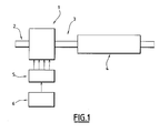
- FIG. 1 shows a motor vehicle engine such as a diesel engine designated by the general reference 1, the inlet of which is connected to gas intake means designated by the general reference 2 and whose outlet is connected to an exhaust line designated by the general reference 3.
- a motor vehicle engine such as a diesel engine designated by the general reference 1
- the inlet of which is connected to gas intake means designated by the general reference 2 and whose outlet is connected to an exhaust line designated by the general reference 3.
- This exhaust line is conventionally provided with pollution control means comprising for example a NOx trap designated by the general reference 4.
- This engine is also associated with common rail fuel supply means designated by the general reference 5 in this figure, having any suitable conventional structure and which are associated with means for controlling their operation designated by the reference general 6, including any engine control computer suitable for causing fuel injections into the engine cylinders.
- such means indeed make it possible to cause different fuel injections in the engine cylinders, for example according to at least one pilot injection, designated by the general reference 10 in FIG. 2, a main injection designated by the general reference 11, possibly associated with one or more post-injections of conventional type, designated by the general reference 12.
- the feed means are also adapted to trigger at least one fuel injection post-injection between -150 ° and -360 ° crankshaft, that is to say after the top dead point of combustion, such as than that designated by the general reference 13 in this Figure 2, to switch to a rich mixture.
- the -360 ° crankshaft terminal corresponds to the closing of the exhaust valves of the cylinder concerned.
- this second quantity of fuel injected late in the cycle is determined as a function of engine speed and load and this quantity can be determined, for example, from a predetermined injection map as a function of this regime and of this load, established during a test campaign.
- an elementary amount of fuel can be injected into each cylinder each cycle of the engine.
- n elementary quantities of fuel can also be injected into each cylinder during the n motor cycles, as illustrated for example by the quantities 4q and 2q, respectively in FIG.
- an engine cycle represents two crankshaft revolutions or 720 °.
- Each cylinder is then injected 4q of fuel every four engine cycles, that is to say every eight crankshaft turns for a four-stroke engine.
- a quantity 2q in each cylinder can also be considered, but it is then applied to only one engine cycle out of two. By engine cycle, two of the four cylinders can thus receive such a post-injection.
- the total HC and methane levels are represented at engine output as a function of the richness at source, that is to say the richness obtained with the first one.
- there is clearly a low methane emission for optimal adjustment consisting of injecting a first quantity of fuel which makes it possible to obtain a lambda at around 1.1 (lambda at the source), plus a second quantity of fuel in the late post-injection, which allows to obtain a lambda of 0.92 at the output of the engine, this with certainly an increase in total HC, but not problematic insofar as these HC can be treated in the NOx trap.
Landscapes
- Engineering & Computer Science (AREA)
- Chemical & Material Sciences (AREA)
- Combustion & Propulsion (AREA)
- Mechanical Engineering (AREA)
- General Engineering & Computer Science (AREA)
- Electrical Control Of Air Or Fuel Supplied To Internal-Combustion Engine (AREA)
- Exhaust Gas After Treatment (AREA)
- Control Of Vehicle Engines Or Engines For Specific Uses (AREA)
- Output Control And Ontrol Of Special Type Engine (AREA)
Abstract
Description
- La présente invention concerne un système d'aide à la régénération d'un piège à NOx intégré dans une ligne d'échappement d'un moteur de véhicule automobile.
- Plus particulièrement, l'invention se rapporte à un tel système d'aide à la régénération d'un piège à NOx intégré dans une ligne d'échappement d'un moteur par exemple Diesel de véhicule automobile, dans lequel ce moteur est associé à des moyens à rampe commune d'alimentation en carburant associés à des moyens de pilotage de leur fonctionnement, de manière à provoquer des injections de carburant dans les cylindres du moteur, pour basculer celui-ci entre des fonctionnements en mélanges riche et pauvre.
- Un piège à NOx est un système de réduction des émissions polluantes, qui traite les NOx grâce à un fonctionnement séquentiel de stockage/déstockage des NOx, c'est-à-dire fonctionnant en mélange pauvre dans lequel la richesse du mélange air/carburant est inférieure à 1 et en mélange riche dans lequel la richesse de ce mélange air/carburant est supérieure à 1.
- Quand le piège est saturé en NOx, il est régénéré par un basculement du moteur en mode riche avec production de réducteurs comme entre autres HC et CO.
- Ce basculement en mode riche est caractérisé par des modifications de paramètres comme la richesse, par diminution du débit d'air admis dans le moteur et une augmentation du débit de carburant, augmentation de la recirculation des gaz d'échappement en entrée de celui-ci (EGR) et utilisation d'une ou de plusieurs post-injections de carburant dans les cylindres du moteur.
- Les émissions d'HC sur un moteur Diesel qui fonctionne en mode riche sont très importantes et plus ou moins inévitables à cause du réglage moteur qui utilise notamment une post-injection pour fonctionner dans ce mode.
- Le problème est que dans ces émissions d'hydrocarbures, une proportion importante est constituée de méthane qui est un gaz très stable. En effet, celui-ci n'est converti qu'à très haute température dans le piège à NOx, c'est-à-dire à une température par exemple supérieure à 600°C. La température des gaz d'échappement atteignant rarement cette valeur dans un piège à NOx lors d'une purge DeNOx, il s'ensuit un risque d'avoir un niveau d'HC trop important en sortie de la ligne d'échappement.
- L'expérience montre que cette proportion importante de méthane est la conséquence à la fois du processus de combustion à richesse élevée dans la chambre et de la façon dont est injecté le carburant dans le cycle.
- Le but de l'invention est donc de résoudre ces problèmes.
- A cet effet, l'invention a pour objet un système d'aide à la régénération d'un piège à NOx intégré dans une ligne d'échappement d'un moteur de véhicule automobile, dans lequel le moteur est associé à des moyens à rampe commune d'alimentation en carburant, associés à des moyens de pilotage de leur fonctionnement, de manière à provoquer des injections de carburant dans les cylindres du moteur, pour basculer celui-ci entre des fonctionnements en mélanges riche et pauvre, caractérisé en ce que les moyens d'alimentation sont adaptés pour déclencher au moins une post-injection de carburant, comprise entre -150° et -360° vilebrequin, afin de basculer en mélange riche.
- Suivant d'autres caractéristiques de l'invention :
- la quantité de carburant injectée est déterminée en fonction du régime et de la charge du moteur ;
- la quantité de carburant est déterminée à partir d'une cartographie d'injection prédéterminée en fonction du régime et de la charge du moteur ;
- une quantité élémentaire de carburant est injectée dans chaque cylindre à chaque cycle du moteur ; et
- n quantités élémentaires de carburant sont injectées dans chaque cylindre tous les n cycles moteur.
- L'invention sera mieux comprise à la lecture de la description qui va suivre, donnée uniquement à titre d'exemple et faite en se référant aux dessins annexés, sur lesquels :
- la Fig.1 représente un schéma synoptique illustrant la structure générale d'un système d'aide selon l'invention ;
- la Fig.2 illustre les différentes injections mises en oeuvre dans un système selon l'invention ;
- la Fig.3 représente différentes variantes d'injection ; et
- la Fig.4 illustre les résultats obtenus.
- On reconnaît en effet sur la figure 1, un moteur de véhicule automobile tel qu'un moteur Diesel désigné par la référence générale 1, dont l'entrée est reliée à des moyens d'admission des gaz désignés par la référence générale 2 et dont la sortie est reliée à une ligne d'échappement désignée par la référence générale 3.
- Cette ligne d'échappement est munie de façon classique de moyens de dépollution comprenant par exemple un piège à NOx désigné par la référence générale 4.
- Ce moteur est également associé à des moyens à rampe commune d'alimentation en carburant désignés par la référence générale 5 sur cette figure, présentant n'importe quelle structure classique appropriée et qui sont associés à des moyens de pilotage de leur fonctionnement désignés par la référence générale 6, comprenant tout calculateur de contrôle moteur approprié pour provoquer des injections de carburant dans les cylindres du moteur.
- Comme cela est illustré sur la figure 2, de tels moyens permettent en effet de provoquer différentes injections de carburant dans les cylindres du moteur, selon par exemple au moins une injection pilote, désignée par la référence générale 10 sur cette figure 2, une injection principale désignée par la référence générale 11, associée éventuellement à une ou plusieurs post-injections de type classique, désignées par la référence générale 12.
- Selon l'invention, les moyens d'alimentation sont également adaptés pour déclencher au moins une post-injection de carburant comprise entre -150° et -360° vilebrequin, c'est-à-dire après le point mort haut de combustion, telle que celle désignée par la référence générale 13 sur cette figure 2, pour basculer en mélange riche.
- La borne à -360° vilebrequin correspond à la fermeture des soupapes d'échappement du cylindre concerné.
- Ainsi, l'invention consiste à injecter une première quantité de carburant via une ou plusieurs injections, permettant d'obtenir une combustion et une richesse plus faible que l'objectif pour limiter la création de méthane (Lambda =1,1 par exemple, au lieu de 0,9), puis une deuxième quantité de carburant très tard dans le cycle de manière à ce que ce carburant injecté ne participe pas ou très peu à la combustion pour ne pas créer de méthane.
- En fait, cette deuxième quantité de carburant injectée tard dans le cycle est déterminée en fonction du régime et de la charge du moteur et cette quantité peut être déterminée par exemple à partir d'une cartographie d'injection prédéterminée en fonction de ce régime et de cette charge, établie lors d'une campagne d'essais.
- Comme cela est illustré sur la figure 3, différentes variantes d'injection peuvent être envisagées.
- C'est ainsi par exemple, qu'une quantité élémentaire de carburant peut être injectée dans chaque cylindre à chaque cycle du moteur.
- Cependant, n quantités élémentaires de carburant peuvent également être injectées dans chaque cylindre tout les n cycles moteur, comme cela est illustré par exemple par les quantités 4q et 2q, respectivement sur la figure 3.
- Dans l'exemple illustré d'un moteur à quatre cylindres, un cycle moteur représente deux tours de vilebrequin ou 720°.
- Ainsi, au lieu d'appliquer une post-injection de quantité q à chaque cylindre individuellement et à chaque cycle moteur (2 tours ou 720° vilebrequin pour un moteur à quatre temps), on peut imaginer que dans le cas d'un moteur à quatre cylindres, on injecte une quantité 4q dans un cylindre et on fait tourner les cylindres où on injecte de façon cyclique, cette post-injection tardive.
- Chaque cylindre se voit alors injecter 4q de carburant tous les quatre cycles moteur, c'est-à-dire tous les huit tours vilebrequin pour un moteur à quatre temps.
- Une quantité 2q dans chaque cylindre peut également être envisagée, mais on ne l'applique alors qu'à un cycle moteur sur deux. Par cycle moteur, deux des quatre cylindres, peuvent ainsi recevoir une telle post-injection.
- La figure 4 basée sur des essais et des simulations, montre l'intérêt d'une telle stratégie de réglage vis à vis du compromis méthane/HC totaux. On constate clairement à la vue de cette figure, le niveau élevé de méthane lorsque la richesse est importante.
- Avec la stratégie mise en oeuvre dans un système selon l'invention, les niveaux d'HC totaux et de méthane sont représentés en sortie moteur en fonction de la richesse à la source, c'est-à-dire la richesse obtenue avec la première quantité injectée, richesse en sortie moteur égale à lambda =0,92 obtenue avec l'ensemble des injections. Dans ces configurations, on constate clairement une faible émission de méthane pour un réglage optimal consistant à injecter une première quantité de carburant qui permet d'obtenir un lambda aux alentours de 1,1 (lambda à la source), plus une deuxième quantité de carburant dans la post-injection tardive, qui permet d'obtenir un lambda de 0,92 en sortie du moteur, ceci avec certes une augmentation d'HC totaux, mais non problématique dans la mesure où ces HC peuvent être traités dans le piège à NOx.
- Bien entendu, d'autres modes de réalisation encore peuvent être envisagés.
Claims (5)
- Système d'aide à la régénération d'un piège à NOx (4) intégré dans une ligne d'échappement (3) d'un moteur (1) de véhicule automobile, dans lequel le moteur (1) est associé à des moyens (5) à rampe commune d'alimentation en carburant, associés à des moyens de pilotage (6) de leur fonctionnement, de manière à provoquer des injections (10, 11, 12) de carburant dans les cylindres du moteur, pour basculer celui-ci entre des fonctionnements en mélanges riche et pauvre, caractérisé en ce que les moyens d'alimentation (5, 6) sont adaptés pour déclencher au moins une post-injection (13) de carburant, comprise entre -150° et -360° vilebrequin, afin de basculer en mélange riche.
- Système selon la revendication 1, caractérisé en ce que la quantité de carburant injectée est déterminée en fonction du régime et de la charge du moteur.
- Système selon la revendication 1 ou 2, caractérisé en ce que la quantité de carburant est déterminée à partir d'une cartographie d'injection prédéterminée en fonction du régime et de la charge du moteur.
- Système selon l'une quelconque des revendications précédentes, caractérisé en ce qu'une quantité élémentaire de carburant est injectée dans chaque cylindre à chaque cycle du moteur.
- Système selon l'une quelconque des revendications 1 à 4, caractérisé en ce que n quantités élémentaires de carburant sont injectées dans chaque cylindre tous les n cycles moteur.
Applications Claiming Priority (1)
| Application Number | Priority Date | Filing Date | Title |
|---|---|---|---|
| FR0501649A FR2882101B1 (fr) | 2005-02-17 | 2005-02-17 | SYSTEME D'AIDE A LA REGENERATION D'UN PIEGE A NOx INTEGRE DANS UNE LIGNE D'ECHAPPEMENT D'UN MOTEUR DE VEHICULE AUTOMOBILE |
Publications (2)
| Publication Number | Publication Date |
|---|---|
| EP1703105A1 true EP1703105A1 (fr) | 2006-09-20 |
| EP1703105B1 EP1703105B1 (fr) | 2010-04-21 |
Family
ID=34954530
Family Applications (1)
| Application Number | Title | Priority Date | Filing Date |
|---|---|---|---|
| EP05292488A Expired - Lifetime EP1703105B1 (fr) | 2005-02-17 | 2005-11-23 | Système d'aide à la régénération d'un piège à NOx intégré dans une ligne d'échappement d'un moteur de véhicule automobile |
Country Status (4)
| Country | Link |
|---|---|
| EP (1) | EP1703105B1 (fr) |
| AT (1) | ATE465336T1 (fr) |
| DE (1) | DE602005020737D1 (fr) |
| FR (1) | FR2882101B1 (fr) |
Citations (4)
| Publication number | Priority date | Publication date | Assignee | Title |
|---|---|---|---|---|
| JPH07259533A (ja) * | 1994-03-23 | 1995-10-09 | Nippon Soken Inc | 内燃機関の排気微粒子浄化装置 |
| EP1174598A2 (fr) * | 2000-07-21 | 2002-01-23 | Toyota Jidosha Kabushiki Kaisha | Dispositif de purification des gaz d'échappement d'un moteur à combustion interne |
| US6412276B1 (en) * | 1999-04-06 | 2002-07-02 | Peugeot Citroen Automobiles Sa | Regeneration system for a diesel engine exhaust gas particulate filter |
| US20030168039A1 (en) * | 2001-12-04 | 2003-09-11 | Oliver Ebelsheiser | Method for operating an internal combustion engine |
-
2005
- 2005-02-17 FR FR0501649A patent/FR2882101B1/fr not_active Expired - Fee Related
- 2005-11-23 DE DE602005020737T patent/DE602005020737D1/de not_active Expired - Lifetime
- 2005-11-23 EP EP05292488A patent/EP1703105B1/fr not_active Expired - Lifetime
- 2005-11-23 AT AT05292488T patent/ATE465336T1/de not_active IP Right Cessation
Patent Citations (4)
| Publication number | Priority date | Publication date | Assignee | Title |
|---|---|---|---|---|
| JPH07259533A (ja) * | 1994-03-23 | 1995-10-09 | Nippon Soken Inc | 内燃機関の排気微粒子浄化装置 |
| US6412276B1 (en) * | 1999-04-06 | 2002-07-02 | Peugeot Citroen Automobiles Sa | Regeneration system for a diesel engine exhaust gas particulate filter |
| EP1174598A2 (fr) * | 2000-07-21 | 2002-01-23 | Toyota Jidosha Kabushiki Kaisha | Dispositif de purification des gaz d'échappement d'un moteur à combustion interne |
| US20030168039A1 (en) * | 2001-12-04 | 2003-09-11 | Oliver Ebelsheiser | Method for operating an internal combustion engine |
Non-Patent Citations (1)
| Title |
|---|
| PATENT ABSTRACTS OF JAPAN vol. 1996, no. 02 29 February 1996 (1996-02-29) * |
Also Published As
| Publication number | Publication date |
|---|---|
| EP1703105B1 (fr) | 2010-04-21 |
| ATE465336T1 (de) | 2010-05-15 |
| DE602005020737D1 (de) | 2010-06-02 |
| FR2882101A1 (fr) | 2006-08-18 |
| FR2882101B1 (fr) | 2007-05-11 |
Similar Documents
| Publication | Publication Date | Title |
|---|---|---|
| EP1086304B1 (fr) | Systeme de regeneration pour un filtre a particules de gaz d'echappement de moteur diesel | |
| EP1310656B1 (fr) | Système d'aide à la régénération de moyens de dépollution intégrés dans une ligne d'échappement d'un moteur de véhicule automobile | |
| FR2648516A1 (fr) | Procede et dispositif de commande pour envoyer du carburant aux cylindres d'un moteur a combustion interne a plusieurs cylindres | |
| FR2833037A1 (fr) | Procede de fonctionnement d'un moteur a combustion interne | |
| JP3324039B2 (ja) | 希薄な燃料−空気混合気で運転されるガソリン機関の有害な排気ガス放出物の減少方法 | |
| EP1632668B1 (fr) | Procédé de contrôle d'un moteur à combustion interne à injection directe de carburant et moteur utilisant un tel procédé | |
| FR2891308A1 (fr) | Procede de gestion d'un moteur a combustion a auto-allumage controle | |
| FR2872203A1 (fr) | Systeme d'aide a la regeneration de moyens de depollution | |
| AU2010202379A1 (en) | NOx adsorber regeneration control strategy for a diesel engine during lean-rich modulation | |
| EP3673165B1 (fr) | Procede de pilotage d'un moteur thermique en fonction de conditions thermodynamiques dans les lignes d'admission et d'echappement | |
| FR2868481A1 (fr) | Procede de controle de la recirculation des gaz d'echappement d'un moteur suralimente a combustion interne et moteur utilisant un tel procede | |
| EP1703105B1 (fr) | Système d'aide à la régénération d'un piège à NOx intégré dans une ligne d'échappement d'un moteur de véhicule automobile | |
| EP4168662A1 (fr) | Contrôle de l'avance à l'injection sur un moteur à combustion diesel | |
| FR2883041A1 (fr) | Systeme de controle du basculement du fonctionnement d'un moteur de vehicule automobile entre des modes pauvre et riche | |
| EP1106804A1 (fr) | Procédé de commande d'un groupe motopropulseur de véhicules automobile pour augmenter la richesse des gaz d'échappement en phase de régénération d'un piège à oxydes d'azote. | |
| FR2891309A1 (fr) | Procede de gestion d'un moteur a combustion | |
| FR2717227A1 (fr) | Procédé d'injection de carburant pour moteur à combustion interne à injection directe et allumage commandé. | |
| FR2883042A1 (fr) | Systeme de controle du basculement du fonctionnement d'un moteur de vehicule automobile entre des modes riche et pauvre | |
| EP2562400A1 (fr) | Procédé de régénération d'un filtre à particules de moteur à combustion interne | |
| FR3153112A1 (fr) | Procédé de commande d’un moteur utilisant du carburant gazeux en phase de démarrage à froid | |
| EP3237732A1 (fr) | Procédé de diagnostic d'un piège a oxydes d'azote et dispositif associé | |
| FR2983531A1 (fr) | Alimentation en mode riche d'un moteur a combustion interne a double pre-injection | |
| FR2855218A1 (fr) | Procede et systeme de gestion de la regeneration d'un filtre a particules et moteur a combustion interne equipe d'un tel filtres a particules | |
| FR2882102A1 (fr) | Systeme d'aide a la regeneration de moyens de depollution integres dans une ligne d'echappement d'un moteur de vehicule | |
| EP1653068A2 (fr) | Procédé de commande d'un moteur comportant une injection de carburant en deux phases |
Legal Events
| Date | Code | Title | Description |
|---|---|---|---|
| PUAI | Public reference made under article 153(3) epc to a published international application that has entered the european phase |
Free format text: ORIGINAL CODE: 0009012 |
|
| AK | Designated contracting states |
Kind code of ref document: A1 Designated state(s): AT BE BG CH CY CZ DE DK EE ES FI FR GB GR HU IE IS IT LI LT LU LV MC NL PL PT RO SE SI SK TR |
|
| AX | Request for extension of the european patent |
Extension state: AL BA HR MK YU |
|
| 17P | Request for examination filed |
Effective date: 20070303 |
|
| 17Q | First examination report despatched |
Effective date: 20070329 |
|
| AKX | Designation fees paid |
Designated state(s): AT BE BG CH CY CZ DE DK EE ES FI FR GB GR HU IE IS IT LI LT LU LV MC NL PL PT RO SE SI SK TR |
|
| GRAP | Despatch of communication of intention to grant a patent |
Free format text: ORIGINAL CODE: EPIDOSNIGR1 |
|
| GRAS | Grant fee paid |
Free format text: ORIGINAL CODE: EPIDOSNIGR3 |
|
| GRAA | (expected) grant |
Free format text: ORIGINAL CODE: 0009210 |
|
| AK | Designated contracting states |
Kind code of ref document: B1 Designated state(s): AT BE BG CH CY CZ DE DK EE ES FI FR GB GR HU IE IS IT LI LT LU LV MC NL PL PT RO SE SI SK TR |
|
| REG | Reference to a national code |
Ref country code: GB Ref legal event code: FG4D Free format text: NOT ENGLISH |
|
| REG | Reference to a national code |
Ref country code: CH Ref legal event code: EP |
|
| REG | Reference to a national code |
Ref country code: IE Ref legal event code: FG4D Free format text: LANGUAGE OF EP DOCUMENT: FRENCH |
|
| REF | Corresponds to: |
Ref document number: 602005020737 Country of ref document: DE Date of ref document: 20100602 Kind code of ref document: P |
|
| REG | Reference to a national code |
Ref country code: GB Ref legal event code: 746 Effective date: 20100607 |
|
| REG | Reference to a national code |
Ref country code: NL Ref legal event code: VDEP Effective date: 20100421 |
|
| LTIE | Lt: invalidation of european patent or patent extension |
Effective date: 20100421 |
|
| PG25 | Lapsed in a contracting state [announced via postgrant information from national office to epo] |
Ref country code: ES Free format text: LAPSE BECAUSE OF FAILURE TO SUBMIT A TRANSLATION OF THE DESCRIPTION OR TO PAY THE FEE WITHIN THE PRESCRIBED TIME-LIMIT Effective date: 20100801 Ref country code: SE Free format text: LAPSE BECAUSE OF FAILURE TO SUBMIT A TRANSLATION OF THE DESCRIPTION OR TO PAY THE FEE WITHIN THE PRESCRIBED TIME-LIMIT Effective date: 20100421 Ref country code: NL Free format text: LAPSE BECAUSE OF FAILURE TO SUBMIT A TRANSLATION OF THE DESCRIPTION OR TO PAY THE FEE WITHIN THE PRESCRIBED TIME-LIMIT Effective date: 20100421 Ref country code: LT Free format text: LAPSE BECAUSE OF FAILURE TO SUBMIT A TRANSLATION OF THE DESCRIPTION OR TO PAY THE FEE WITHIN THE PRESCRIBED TIME-LIMIT Effective date: 20100421 |
|
| REG | Reference to a national code |
Ref country code: IE Ref legal event code: FD4D |
|
| PG25 | Lapsed in a contracting state [announced via postgrant information from national office to epo] |
Ref country code: LV Free format text: LAPSE BECAUSE OF FAILURE TO SUBMIT A TRANSLATION OF THE DESCRIPTION OR TO PAY THE FEE WITHIN THE PRESCRIBED TIME-LIMIT Effective date: 20100421 Ref country code: IS Free format text: LAPSE BECAUSE OF FAILURE TO SUBMIT A TRANSLATION OF THE DESCRIPTION OR TO PAY THE FEE WITHIN THE PRESCRIBED TIME-LIMIT Effective date: 20100821 Ref country code: FI Free format text: LAPSE BECAUSE OF FAILURE TO SUBMIT A TRANSLATION OF THE DESCRIPTION OR TO PAY THE FEE WITHIN THE PRESCRIBED TIME-LIMIT Effective date: 20100421 Ref country code: AT Free format text: LAPSE BECAUSE OF FAILURE TO SUBMIT A TRANSLATION OF THE DESCRIPTION OR TO PAY THE FEE WITHIN THE PRESCRIBED TIME-LIMIT Effective date: 20100421 Ref country code: SI Free format text: LAPSE BECAUSE OF FAILURE TO SUBMIT A TRANSLATION OF THE DESCRIPTION OR TO PAY THE FEE WITHIN THE PRESCRIBED TIME-LIMIT Effective date: 20100421 |
|
| PG25 | Lapsed in a contracting state [announced via postgrant information from national office to epo] |
Ref country code: CY Free format text: LAPSE BECAUSE OF FAILURE TO SUBMIT A TRANSLATION OF THE DESCRIPTION OR TO PAY THE FEE WITHIN THE PRESCRIBED TIME-LIMIT Effective date: 20100505 Ref country code: PL Free format text: LAPSE BECAUSE OF FAILURE TO SUBMIT A TRANSLATION OF THE DESCRIPTION OR TO PAY THE FEE WITHIN THE PRESCRIBED TIME-LIMIT Effective date: 20100421 Ref country code: GR Free format text: LAPSE BECAUSE OF FAILURE TO SUBMIT A TRANSLATION OF THE DESCRIPTION OR TO PAY THE FEE WITHIN THE PRESCRIBED TIME-LIMIT Effective date: 20100722 |
|
| PG25 | Lapsed in a contracting state [announced via postgrant information from national office to epo] |
Ref country code: EE Free format text: LAPSE BECAUSE OF FAILURE TO SUBMIT A TRANSLATION OF THE DESCRIPTION OR TO PAY THE FEE WITHIN THE PRESCRIBED TIME-LIMIT Effective date: 20100421 Ref country code: PT Free format text: LAPSE BECAUSE OF FAILURE TO SUBMIT A TRANSLATION OF THE DESCRIPTION OR TO PAY THE FEE WITHIN THE PRESCRIBED TIME-LIMIT Effective date: 20100823 Ref country code: IE Free format text: LAPSE BECAUSE OF FAILURE TO SUBMIT A TRANSLATION OF THE DESCRIPTION OR TO PAY THE FEE WITHIN THE PRESCRIBED TIME-LIMIT Effective date: 20100421 Ref country code: DK Free format text: LAPSE BECAUSE OF FAILURE TO SUBMIT A TRANSLATION OF THE DESCRIPTION OR TO PAY THE FEE WITHIN THE PRESCRIBED TIME-LIMIT Effective date: 20100421 |
|
| PLBE | No opposition filed within time limit |
Free format text: ORIGINAL CODE: 0009261 |
|
| STAA | Information on the status of an ep patent application or granted ep patent |
Free format text: STATUS: NO OPPOSITION FILED WITHIN TIME LIMIT |
|
| PG25 | Lapsed in a contracting state [announced via postgrant information from national office to epo] |
Ref country code: CZ Free format text: LAPSE BECAUSE OF FAILURE TO SUBMIT A TRANSLATION OF THE DESCRIPTION OR TO PAY THE FEE WITHIN THE PRESCRIBED TIME-LIMIT Effective date: 20100421 Ref country code: SK Free format text: LAPSE BECAUSE OF FAILURE TO SUBMIT A TRANSLATION OF THE DESCRIPTION OR TO PAY THE FEE WITHIN THE PRESCRIBED TIME-LIMIT Effective date: 20100421 Ref country code: RO Free format text: LAPSE BECAUSE OF FAILURE TO SUBMIT A TRANSLATION OF THE DESCRIPTION OR TO PAY THE FEE WITHIN THE PRESCRIBED TIME-LIMIT Effective date: 20100421 |
|
| 26N | No opposition filed |
Effective date: 20110124 |
|
| PG25 | Lapsed in a contracting state [announced via postgrant information from national office to epo] |
Ref country code: IT Free format text: LAPSE BECAUSE OF FAILURE TO SUBMIT A TRANSLATION OF THE DESCRIPTION OR TO PAY THE FEE WITHIN THE PRESCRIBED TIME-LIMIT Effective date: 20100421 |
|
| BERE | Be: lapsed |
Owner name: PEUGEOT CITROEN AUTOMOBILES S.A. Effective date: 20101130 |
|
| PG25 | Lapsed in a contracting state [announced via postgrant information from national office to epo] |
Ref country code: MC Free format text: LAPSE BECAUSE OF NON-PAYMENT OF DUE FEES Effective date: 20101130 |
|
| REG | Reference to a national code |
Ref country code: CH Ref legal event code: PL |
|
| PG25 | Lapsed in a contracting state [announced via postgrant information from national office to epo] |
Ref country code: LI Free format text: LAPSE BECAUSE OF NON-PAYMENT OF DUE FEES Effective date: 20101130 Ref country code: CH Free format text: LAPSE BECAUSE OF NON-PAYMENT OF DUE FEES Effective date: 20101130 |
|
| PG25 | Lapsed in a contracting state [announced via postgrant information from national office to epo] |
Ref country code: BE Free format text: LAPSE BECAUSE OF NON-PAYMENT OF DUE FEES Effective date: 20101130 |
|
| PG25 | Lapsed in a contracting state [announced via postgrant information from national office to epo] |
Ref country code: HU Free format text: LAPSE BECAUSE OF FAILURE TO SUBMIT A TRANSLATION OF THE DESCRIPTION OR TO PAY THE FEE WITHIN THE PRESCRIBED TIME-LIMIT Effective date: 20101022 Ref country code: BG Free format text: LAPSE BECAUSE OF FAILURE TO SUBMIT A TRANSLATION OF THE DESCRIPTION OR TO PAY THE FEE WITHIN THE PRESCRIBED TIME-LIMIT Effective date: 20100421 Ref country code: LU Free format text: LAPSE BECAUSE OF NON-PAYMENT OF DUE FEES Effective date: 20101123 |
|
| PG25 | Lapsed in a contracting state [announced via postgrant information from national office to epo] |
Ref country code: TR Free format text: LAPSE BECAUSE OF FAILURE TO SUBMIT A TRANSLATION OF THE DESCRIPTION OR TO PAY THE FEE WITHIN THE PRESCRIBED TIME-LIMIT Effective date: 20100421 |
|
| PG25 | Lapsed in a contracting state [announced via postgrant information from national office to epo] |
Ref country code: BG Free format text: LAPSE BECAUSE OF FAILURE TO SUBMIT A TRANSLATION OF THE DESCRIPTION OR TO PAY THE FEE WITHIN THE PRESCRIBED TIME-LIMIT Effective date: 20100721 |
|
| REG | Reference to a national code |
Ref country code: FR Ref legal event code: PLFP Year of fee payment: 11 |
|
| REG | Reference to a national code |
Ref country code: FR Ref legal event code: PLFP Year of fee payment: 12 |
|
| PGFP | Annual fee paid to national office [announced via postgrant information from national office to epo] |
Ref country code: GB Payment date: 20161027 Year of fee payment: 12 |
|
| REG | Reference to a national code |
Ref country code: FR Ref legal event code: PLFP Year of fee payment: 13 |
|
| REG | Reference to a national code |
Ref country code: FR Ref legal event code: CA Effective date: 20180312 Ref country code: FR Ref legal event code: CD Owner name: PEUGEOT CITROEN AUTOMOBILES SA, FR Effective date: 20180312 |
|
| GBPC | Gb: european patent ceased through non-payment of renewal fee |
Effective date: 20171123 |
|
| REG | Reference to a national code |
Ref country code: FR Ref legal event code: PLFP Year of fee payment: 14 |
|
| PG25 | Lapsed in a contracting state [announced via postgrant information from national office to epo] |
Ref country code: GB Free format text: LAPSE BECAUSE OF NON-PAYMENT OF DUE FEES Effective date: 20171123 |
|
| PGFP | Annual fee paid to national office [announced via postgrant information from national office to epo] |
Ref country code: DE Payment date: 20191021 Year of fee payment: 15 |
|
| REG | Reference to a national code |
Ref country code: DE Ref legal event code: R119 Ref document number: 602005020737 Country of ref document: DE |
|
| PG25 | Lapsed in a contracting state [announced via postgrant information from national office to epo] |
Ref country code: DE Free format text: LAPSE BECAUSE OF NON-PAYMENT OF DUE FEES Effective date: 20210601 |
|
| PGFP | Annual fee paid to national office [announced via postgrant information from national office to epo] |
Ref country code: FR Payment date: 20211020 Year of fee payment: 17 |
|
| PG25 | Lapsed in a contracting state [announced via postgrant information from national office to epo] |
Ref country code: FR Free format text: LAPSE BECAUSE OF NON-PAYMENT OF DUE FEES Effective date: 20221130 |