EP1702781A2 - Drive unit for hybrid vehicle - Google Patents
Drive unit for hybrid vehicle Download PDFInfo
- Publication number
- EP1702781A2 EP1702781A2 EP06005383A EP06005383A EP1702781A2 EP 1702781 A2 EP1702781 A2 EP 1702781A2 EP 06005383 A EP06005383 A EP 06005383A EP 06005383 A EP06005383 A EP 06005383A EP 1702781 A2 EP1702781 A2 EP 1702781A2
- Authority
- EP
- European Patent Office
- Prior art keywords
- engine
- power
- drive unit
- motor
- gear
- Prior art date
- Legal status (The legal status is an assumption and is not a legal conclusion. Google has not performed a legal analysis and makes no representation as to the accuracy of the status listed.)
- Granted
Links
Images




Classifications
-
- B—PERFORMING OPERATIONS; TRANSPORTING
- B60—VEHICLES IN GENERAL
- B60K—ARRANGEMENT OR MOUNTING OF PROPULSION UNITS OR OF TRANSMISSIONS IN VEHICLES; ARRANGEMENT OR MOUNTING OF PLURAL DIVERSE PRIME-MOVERS IN VEHICLES; AUXILIARY DRIVES FOR VEHICLES; INSTRUMENTATION OR DASHBOARDS FOR VEHICLES; ARRANGEMENTS IN CONNECTION WITH COOLING, AIR INTAKE, GAS EXHAUST OR FUEL SUPPLY OF PROPULSION UNITS IN VEHICLES
- B60K6/00—Arrangement or mounting of plural diverse prime-movers for mutual or common propulsion, e.g. hybrid propulsion systems comprising electric motors and internal combustion engines
- B60K6/20—Arrangement or mounting of plural diverse prime-movers for mutual or common propulsion, e.g. hybrid propulsion systems comprising electric motors and internal combustion engines the prime-movers consisting of electric motors and internal combustion engines, e.g. HEVs
- B60K6/22—Arrangement or mounting of plural diverse prime-movers for mutual or common propulsion, e.g. hybrid propulsion systems comprising electric motors and internal combustion engines the prime-movers consisting of electric motors and internal combustion engines, e.g. HEVs characterised by apparatus, components or means specially adapted for HEVs
- B60K6/24—Arrangement or mounting of plural diverse prime-movers for mutual or common propulsion, e.g. hybrid propulsion systems comprising electric motors and internal combustion engines the prime-movers consisting of electric motors and internal combustion engines, e.g. HEVs characterised by apparatus, components or means specially adapted for HEVs characterised by the combustion engines
-
- B—PERFORMING OPERATIONS; TRANSPORTING
- B60—VEHICLES IN GENERAL
- B60K—ARRANGEMENT OR MOUNTING OF PROPULSION UNITS OR OF TRANSMISSIONS IN VEHICLES; ARRANGEMENT OR MOUNTING OF PLURAL DIVERSE PRIME-MOVERS IN VEHICLES; AUXILIARY DRIVES FOR VEHICLES; INSTRUMENTATION OR DASHBOARDS FOR VEHICLES; ARRANGEMENTS IN CONNECTION WITH COOLING, AIR INTAKE, GAS EXHAUST OR FUEL SUPPLY OF PROPULSION UNITS IN VEHICLES
- B60K6/00—Arrangement or mounting of plural diverse prime-movers for mutual or common propulsion, e.g. hybrid propulsion systems comprising electric motors and internal combustion engines
- B60K6/20—Arrangement or mounting of plural diverse prime-movers for mutual or common propulsion, e.g. hybrid propulsion systems comprising electric motors and internal combustion engines the prime-movers consisting of electric motors and internal combustion engines, e.g. HEVs
- B60K6/22—Arrangement or mounting of plural diverse prime-movers for mutual or common propulsion, e.g. hybrid propulsion systems comprising electric motors and internal combustion engines the prime-movers consisting of electric motors and internal combustion engines, e.g. HEVs characterised by apparatus, components or means specially adapted for HEVs
- B60K6/26—Arrangement or mounting of plural diverse prime-movers for mutual or common propulsion, e.g. hybrid propulsion systems comprising electric motors and internal combustion engines the prime-movers consisting of electric motors and internal combustion engines, e.g. HEVs characterised by apparatus, components or means specially adapted for HEVs characterised by the motors or the generators
-
- B—PERFORMING OPERATIONS; TRANSPORTING
- B60—VEHICLES IN GENERAL
- B60K—ARRANGEMENT OR MOUNTING OF PROPULSION UNITS OR OF TRANSMISSIONS IN VEHICLES; ARRANGEMENT OR MOUNTING OF PLURAL DIVERSE PRIME-MOVERS IN VEHICLES; AUXILIARY DRIVES FOR VEHICLES; INSTRUMENTATION OR DASHBOARDS FOR VEHICLES; ARRANGEMENTS IN CONNECTION WITH COOLING, AIR INTAKE, GAS EXHAUST OR FUEL SUPPLY OF PROPULSION UNITS IN VEHICLES
- B60K6/00—Arrangement or mounting of plural diverse prime-movers for mutual or common propulsion, e.g. hybrid propulsion systems comprising electric motors and internal combustion engines
- B60K6/20—Arrangement or mounting of plural diverse prime-movers for mutual or common propulsion, e.g. hybrid propulsion systems comprising electric motors and internal combustion engines the prime-movers consisting of electric motors and internal combustion engines, e.g. HEVs
- B60K6/22—Arrangement or mounting of plural diverse prime-movers for mutual or common propulsion, e.g. hybrid propulsion systems comprising electric motors and internal combustion engines the prime-movers consisting of electric motors and internal combustion engines, e.g. HEVs characterised by apparatus, components or means specially adapted for HEVs
- B60K6/40—Arrangement or mounting of plural diverse prime-movers for mutual or common propulsion, e.g. hybrid propulsion systems comprising electric motors and internal combustion engines the prime-movers consisting of electric motors and internal combustion engines, e.g. HEVs characterised by apparatus, components or means specially adapted for HEVs characterised by the assembly or relative disposition of components
-
- B—PERFORMING OPERATIONS; TRANSPORTING
- B60—VEHICLES IN GENERAL
- B60K—ARRANGEMENT OR MOUNTING OF PROPULSION UNITS OR OF TRANSMISSIONS IN VEHICLES; ARRANGEMENT OR MOUNTING OF PLURAL DIVERSE PRIME-MOVERS IN VEHICLES; AUXILIARY DRIVES FOR VEHICLES; INSTRUMENTATION OR DASHBOARDS FOR VEHICLES; ARRANGEMENTS IN CONNECTION WITH COOLING, AIR INTAKE, GAS EXHAUST OR FUEL SUPPLY OF PROPULSION UNITS IN VEHICLES
- B60K6/00—Arrangement or mounting of plural diverse prime-movers for mutual or common propulsion, e.g. hybrid propulsion systems comprising electric motors and internal combustion engines
- B60K6/20—Arrangement or mounting of plural diverse prime-movers for mutual or common propulsion, e.g. hybrid propulsion systems comprising electric motors and internal combustion engines the prime-movers consisting of electric motors and internal combustion engines, e.g. HEVs
- B60K6/42—Arrangement or mounting of plural diverse prime-movers for mutual or common propulsion, e.g. hybrid propulsion systems comprising electric motors and internal combustion engines the prime-movers consisting of electric motors and internal combustion engines, e.g. HEVs characterised by the architecture of the hybrid electric vehicle
- B60K6/44—Series-parallel type
- B60K6/445—Differential gearing distribution type
-
- B—PERFORMING OPERATIONS; TRANSPORTING
- B60—VEHICLES IN GENERAL
- B60L—PROPULSION OF ELECTRICALLY-PROPELLED VEHICLES; SUPPLYING ELECTRIC POWER FOR AUXILIARY EQUIPMENT OF ELECTRICALLY-PROPELLED VEHICLES; ELECTRODYNAMIC BRAKE SYSTEMS FOR VEHICLES IN GENERAL; MAGNETIC SUSPENSION OR LEVITATION FOR VEHICLES; MONITORING OPERATING VARIABLES OF ELECTRICALLY-PROPELLED VEHICLES; ELECTRIC SAFETY DEVICES FOR ELECTRICALLY-PROPELLED VEHICLES
- B60L15/00—Methods, circuits, or devices for controlling the traction-motor speed of electrically-propelled vehicles
- B60L15/20—Methods, circuits, or devices for controlling the traction-motor speed of electrically-propelled vehicles for control of the vehicle or its driving motor to achieve a desired performance, e.g. speed, torque, programmed variation of speed
- B60L15/2009—Methods, circuits, or devices for controlling the traction-motor speed of electrically-propelled vehicles for control of the vehicle or its driving motor to achieve a desired performance, e.g. speed, torque, programmed variation of speed for braking
-
- B—PERFORMING OPERATIONS; TRANSPORTING
- B60—VEHICLES IN GENERAL
- B60L—PROPULSION OF ELECTRICALLY-PROPELLED VEHICLES; SUPPLYING ELECTRIC POWER FOR AUXILIARY EQUIPMENT OF ELECTRICALLY-PROPELLED VEHICLES; ELECTRODYNAMIC BRAKE SYSTEMS FOR VEHICLES IN GENERAL; MAGNETIC SUSPENSION OR LEVITATION FOR VEHICLES; MONITORING OPERATING VARIABLES OF ELECTRICALLY-PROPELLED VEHICLES; ELECTRIC SAFETY DEVICES FOR ELECTRICALLY-PROPELLED VEHICLES
- B60L50/00—Electric propulsion with power supplied within the vehicle
- B60L50/10—Electric propulsion with power supplied within the vehicle using propulsion power supplied by engine-driven generators, e.g. generators driven by combustion engines
- B60L50/16—Electric propulsion with power supplied within the vehicle using propulsion power supplied by engine-driven generators, e.g. generators driven by combustion engines with provision for separate direct mechanical propulsion
-
- B—PERFORMING OPERATIONS; TRANSPORTING
- B62—LAND VEHICLES FOR TRAVELLING OTHERWISE THAN ON RAILS
- B62M—RIDER PROPULSION OF WHEELED VEHICLES OR SLEDGES; POWERED PROPULSION OF SLEDGES OR SINGLE-TRACK CYCLES; TRANSMISSIONS SPECIALLY ADAPTED FOR SUCH VEHICLES
- B62M7/00—Motorcycles characterised by position of motor or engine
- B62M7/12—Motorcycles characterised by position of motor or engine with the engine beside or within the driven wheel
-
- B—PERFORMING OPERATIONS; TRANSPORTING
- B60—VEHICLES IN GENERAL
- B60G—VEHICLE SUSPENSION ARRANGEMENTS
- B60G2204/00—Indexing codes related to suspensions per se or to auxiliary parts
- B60G2204/10—Mounting of suspension elements
- B60G2204/30—In-wheel mountings
-
- B—PERFORMING OPERATIONS; TRANSPORTING
- B60—VEHICLES IN GENERAL
- B60L—PROPULSION OF ELECTRICALLY-PROPELLED VEHICLES; SUPPLYING ELECTRIC POWER FOR AUXILIARY EQUIPMENT OF ELECTRICALLY-PROPELLED VEHICLES; ELECTRODYNAMIC BRAKE SYSTEMS FOR VEHICLES IN GENERAL; MAGNETIC SUSPENSION OR LEVITATION FOR VEHICLES; MONITORING OPERATING VARIABLES OF ELECTRICALLY-PROPELLED VEHICLES; ELECTRIC SAFETY DEVICES FOR ELECTRICALLY-PROPELLED VEHICLES
- B60L2200/00—Type of vehicles
- B60L2200/12—Bikes
-
- B—PERFORMING OPERATIONS; TRANSPORTING
- B60—VEHICLES IN GENERAL
- B60L—PROPULSION OF ELECTRICALLY-PROPELLED VEHICLES; SUPPLYING ELECTRIC POWER FOR AUXILIARY EQUIPMENT OF ELECTRICALLY-PROPELLED VEHICLES; ELECTRODYNAMIC BRAKE SYSTEMS FOR VEHICLES IN GENERAL; MAGNETIC SUSPENSION OR LEVITATION FOR VEHICLES; MONITORING OPERATING VARIABLES OF ELECTRICALLY-PROPELLED VEHICLES; ELECTRIC SAFETY DEVICES FOR ELECTRICALLY-PROPELLED VEHICLES
- B60L2220/00—Electrical machine types; Structures or applications thereof
- B60L2220/40—Electrical machine applications
- B60L2220/42—Electrical machine applications with use of more than one motor
-
- B—PERFORMING OPERATIONS; TRANSPORTING
- B60—VEHICLES IN GENERAL
- B60L—PROPULSION OF ELECTRICALLY-PROPELLED VEHICLES; SUPPLYING ELECTRIC POWER FOR AUXILIARY EQUIPMENT OF ELECTRICALLY-PROPELLED VEHICLES; ELECTRODYNAMIC BRAKE SYSTEMS FOR VEHICLES IN GENERAL; MAGNETIC SUSPENSION OR LEVITATION FOR VEHICLES; MONITORING OPERATING VARIABLES OF ELECTRICALLY-PROPELLED VEHICLES; ELECTRIC SAFETY DEVICES FOR ELECTRICALLY-PROPELLED VEHICLES
- B60L2240/00—Control parameters of input or output; Target parameters
- B60L2240/10—Vehicle control parameters
- B60L2240/12—Speed
-
- B—PERFORMING OPERATIONS; TRANSPORTING
- B60—VEHICLES IN GENERAL
- B60L—PROPULSION OF ELECTRICALLY-PROPELLED VEHICLES; SUPPLYING ELECTRIC POWER FOR AUXILIARY EQUIPMENT OF ELECTRICALLY-PROPELLED VEHICLES; ELECTRODYNAMIC BRAKE SYSTEMS FOR VEHICLES IN GENERAL; MAGNETIC SUSPENSION OR LEVITATION FOR VEHICLES; MONITORING OPERATING VARIABLES OF ELECTRICALLY-PROPELLED VEHICLES; ELECTRIC SAFETY DEVICES FOR ELECTRICALLY-PROPELLED VEHICLES
- B60L2240/00—Control parameters of input or output; Target parameters
- B60L2240/40—Drive Train control parameters
- B60L2240/42—Drive Train control parameters related to electric machines
- B60L2240/421—Speed
-
- B—PERFORMING OPERATIONS; TRANSPORTING
- B60—VEHICLES IN GENERAL
- B60Y—INDEXING SCHEME RELATING TO ASPECTS CROSS-CUTTING VEHICLE TECHNOLOGY
- B60Y2200/00—Type of vehicle
- B60Y2200/10—Road Vehicles
- B60Y2200/12—Motorcycles, Trikes; Quads; Scooters
- B60Y2200/126—Scooters
-
- B—PERFORMING OPERATIONS; TRANSPORTING
- B62—LAND VEHICLES FOR TRAVELLING OTHERWISE THAN ON RAILS
- B62K—CYCLES; CYCLE FRAMES; CYCLE STEERING DEVICES; RIDER-OPERATED TERMINAL CONTROLS SPECIALLY ADAPTED FOR CYCLES; CYCLE AXLE SUSPENSIONS; CYCLE SIDECARS, FORECARS, OR THE LIKE
- B62K2202/00—Motorised scooters
-
- F—MECHANICAL ENGINEERING; LIGHTING; HEATING; WEAPONS; BLASTING
- F16—ENGINEERING ELEMENTS AND UNITS; GENERAL MEASURES FOR PRODUCING AND MAINTAINING EFFECTIVE FUNCTIONING OF MACHINES OR INSTALLATIONS; THERMAL INSULATION IN GENERAL
- F16H—GEARING
- F16H37/00—Combinations of mechanical gearings, not provided for in groups F16H1/00 - F16H35/00
- F16H37/02—Combinations of mechanical gearings, not provided for in groups F16H1/00 - F16H35/00 comprising essentially only toothed or friction gearings
- F16H37/06—Combinations of mechanical gearings, not provided for in groups F16H1/00 - F16H35/00 comprising essentially only toothed or friction gearings with a plurality of driving or driven shafts; with arrangements for dividing torque between two or more intermediate shafts
- F16H37/08—Combinations of mechanical gearings, not provided for in groups F16H1/00 - F16H35/00 comprising essentially only toothed or friction gearings with a plurality of driving or driven shafts; with arrangements for dividing torque between two or more intermediate shafts with differential gearing
- F16H37/0833—Combinations of mechanical gearings, not provided for in groups F16H1/00 - F16H35/00 comprising essentially only toothed or friction gearings with a plurality of driving or driven shafts; with arrangements for dividing torque between two or more intermediate shafts with differential gearing with arrangements for dividing torque between two or more intermediate shafts, i.e. with two or more internal power paths
- F16H37/084—Combinations of mechanical gearings, not provided for in groups F16H1/00 - F16H35/00 comprising essentially only toothed or friction gearings with a plurality of driving or driven shafts; with arrangements for dividing torque between two or more intermediate shafts with differential gearing with arrangements for dividing torque between two or more intermediate shafts, i.e. with two or more internal power paths at least one power path being a continuously variable transmission, i.e. CVT
- F16H2037/0866—Power-split transmissions with distributing differentials, with the output of the CVT connected or connectable to the output shaft
-
- Y—GENERAL TAGGING OF NEW TECHNOLOGICAL DEVELOPMENTS; GENERAL TAGGING OF CROSS-SECTIONAL TECHNOLOGIES SPANNING OVER SEVERAL SECTIONS OF THE IPC; TECHNICAL SUBJECTS COVERED BY FORMER USPC CROSS-REFERENCE ART COLLECTIONS [XRACs] AND DIGESTS
- Y02—TECHNOLOGIES OR APPLICATIONS FOR MITIGATION OR ADAPTATION AGAINST CLIMATE CHANGE
- Y02T—CLIMATE CHANGE MITIGATION TECHNOLOGIES RELATED TO TRANSPORTATION
- Y02T10/00—Road transport of goods or passengers
- Y02T10/60—Other road transportation technologies with climate change mitigation effect
- Y02T10/62—Hybrid vehicles
-
- Y—GENERAL TAGGING OF NEW TECHNOLOGICAL DEVELOPMENTS; GENERAL TAGGING OF CROSS-SECTIONAL TECHNOLOGIES SPANNING OVER SEVERAL SECTIONS OF THE IPC; TECHNICAL SUBJECTS COVERED BY FORMER USPC CROSS-REFERENCE ART COLLECTIONS [XRACs] AND DIGESTS
- Y02—TECHNOLOGIES OR APPLICATIONS FOR MITIGATION OR ADAPTATION AGAINST CLIMATE CHANGE
- Y02T—CLIMATE CHANGE MITIGATION TECHNOLOGIES RELATED TO TRANSPORTATION
- Y02T10/00—Road transport of goods or passengers
- Y02T10/60—Other road transportation technologies with climate change mitigation effect
- Y02T10/64—Electric machine technologies in electromobility
-
- Y—GENERAL TAGGING OF NEW TECHNOLOGICAL DEVELOPMENTS; GENERAL TAGGING OF CROSS-SECTIONAL TECHNOLOGIES SPANNING OVER SEVERAL SECTIONS OF THE IPC; TECHNICAL SUBJECTS COVERED BY FORMER USPC CROSS-REFERENCE ART COLLECTIONS [XRACs] AND DIGESTS
- Y02—TECHNOLOGIES OR APPLICATIONS FOR MITIGATION OR ADAPTATION AGAINST CLIMATE CHANGE
- Y02T—CLIMATE CHANGE MITIGATION TECHNOLOGIES RELATED TO TRANSPORTATION
- Y02T10/00—Road transport of goods or passengers
- Y02T10/60—Other road transportation technologies with climate change mitigation effect
- Y02T10/70—Energy storage systems for electromobility, e.g. batteries
-
- Y—GENERAL TAGGING OF NEW TECHNOLOGICAL DEVELOPMENTS; GENERAL TAGGING OF CROSS-SECTIONAL TECHNOLOGIES SPANNING OVER SEVERAL SECTIONS OF THE IPC; TECHNICAL SUBJECTS COVERED BY FORMER USPC CROSS-REFERENCE ART COLLECTIONS [XRACs] AND DIGESTS
- Y02—TECHNOLOGIES OR APPLICATIONS FOR MITIGATION OR ADAPTATION AGAINST CLIMATE CHANGE
- Y02T—CLIMATE CHANGE MITIGATION TECHNOLOGIES RELATED TO TRANSPORTATION
- Y02T10/00—Road transport of goods or passengers
- Y02T10/60—Other road transportation technologies with climate change mitigation effect
- Y02T10/7072—Electromobility specific charging systems or methods for batteries, ultracapacitors, supercapacitors or double-layer capacitors
-
- Y—GENERAL TAGGING OF NEW TECHNOLOGICAL DEVELOPMENTS; GENERAL TAGGING OF CROSS-SECTIONAL TECHNOLOGIES SPANNING OVER SEVERAL SECTIONS OF THE IPC; TECHNICAL SUBJECTS COVERED BY FORMER USPC CROSS-REFERENCE ART COLLECTIONS [XRACs] AND DIGESTS
- Y02—TECHNOLOGIES OR APPLICATIONS FOR MITIGATION OR ADAPTATION AGAINST CLIMATE CHANGE
- Y02T—CLIMATE CHANGE MITIGATION TECHNOLOGIES RELATED TO TRANSPORTATION
- Y02T10/00—Road transport of goods or passengers
- Y02T10/60—Other road transportation technologies with climate change mitigation effect
- Y02T10/72—Electric energy management in electromobility
-
- Y—GENERAL TAGGING OF NEW TECHNOLOGICAL DEVELOPMENTS; GENERAL TAGGING OF CROSS-SECTIONAL TECHNOLOGIES SPANNING OVER SEVERAL SECTIONS OF THE IPC; TECHNICAL SUBJECTS COVERED BY FORMER USPC CROSS-REFERENCE ART COLLECTIONS [XRACs] AND DIGESTS
- Y10—TECHNICAL SUBJECTS COVERED BY FORMER USPC
- Y10S—TECHNICAL SUBJECTS COVERED BY FORMER USPC CROSS-REFERENCE ART COLLECTIONS [XRACs] AND DIGESTS
- Y10S903/00—Hybrid electric vehicles, HEVS
- Y10S903/902—Prime movers comprising electrical and internal combustion motors
- Y10S903/903—Prime movers comprising electrical and internal combustion motors having energy storing means, e.g. battery, capacitor
- Y10S903/904—Component specially adapted for hev
- Y10S903/915—Specific drive or transmission adapted for hev
- Y10S903/916—Specific drive or transmission adapted for hev with plurality of drive axles
-
- Y—GENERAL TAGGING OF NEW TECHNOLOGICAL DEVELOPMENTS; GENERAL TAGGING OF CROSS-SECTIONAL TECHNOLOGIES SPANNING OVER SEVERAL SECTIONS OF THE IPC; TECHNICAL SUBJECTS COVERED BY FORMER USPC CROSS-REFERENCE ART COLLECTIONS [XRACs] AND DIGESTS
- Y10—TECHNICAL SUBJECTS COVERED BY FORMER USPC
- Y10S—TECHNICAL SUBJECTS COVERED BY FORMER USPC CROSS-REFERENCE ART COLLECTIONS [XRACs] AND DIGESTS
- Y10S903/00—Hybrid electric vehicles, HEVS
- Y10S903/902—Prime movers comprising electrical and internal combustion motors
- Y10S903/903—Prime movers comprising electrical and internal combustion motors having energy storing means, e.g. battery, capacitor
- Y10S903/951—Assembly or relative location of components
-
- Y—GENERAL TAGGING OF NEW TECHNOLOGICAL DEVELOPMENTS; GENERAL TAGGING OF CROSS-SECTIONAL TECHNOLOGIES SPANNING OVER SEVERAL SECTIONS OF THE IPC; TECHNICAL SUBJECTS COVERED BY FORMER USPC CROSS-REFERENCE ART COLLECTIONS [XRACs] AND DIGESTS
- Y10—TECHNICAL SUBJECTS COVERED BY FORMER USPC
- Y10S—TECHNICAL SUBJECTS COVERED BY FORMER USPC CROSS-REFERENCE ART COLLECTIONS [XRACs] AND DIGESTS
- Y10S903/00—Hybrid electric vehicles, HEVS
- Y10S903/902—Prime movers comprising electrical and internal combustion motors
- Y10S903/903—Prime movers comprising electrical and internal combustion motors having energy storing means, e.g. battery, capacitor
- Y10S903/952—Housing details
Definitions
- This invention relates to a drive unit for a hybrid vehicle (a hybrid type drive unit), including an engine and an electric motor both mounted on a vehicle and selectively used for driving a drive wheel, and a hybrid vehicle having this drive unit, particularly a hybrid type motorcycle.
- a hybrid vehicle there can be a parallel hybrid type vehicle in which a drive wheel(s) is driven by either one of an engine and a drive motor switched between them, in response to, for example, a running condition of the vehicle or a remaining power amount of a battery charged by a generator.
- a series hybrid type vehicle in which an engine drives a generator to drive a drive motor for driving a drive wheel(s), using the electric power generated by the generator.
- JP-A-2000-343964 an example of a drive unit of the parallel hybrid type vehicles (particularly, four wheeled vehicles) is shown in JP-A-2000-343964 .
- the drive unit disclosed in JP-A-2000-343964 includes an engine, a generator, a power distributing mechanism distributing the drive power of the engine between the generator and drive wheels and an electric motor driving the drive wheels by the electric power of the generator.
- the engine, the generator, the power distributing mechanism and the motor are coaxially arranged in a transverse direction of the vehicle so as to be a rational arrangement in a viewpoint of the power transmission.
- a power transmitting shaft coaxially disposed with the crankshaft is coupled with an end of the crankshaft through a clutch.
- the power transmitting shaft extends through the generator to have an axis of a planetary gear set of the power distributing mechanism including a sun gear and a ring gear.
- the power transmitting shaft also extends through the motor.
- the power transmitting shaft thus can be the longest and the thinnest member in the structure of the drive unit.
- the power transmitting shaft is connected to a planetary gear carrier supporting planetary gears for rotation, while the power transmitting shaft extends through the power distributing mechanism.
- a mount space for the drive unit is limited to a portion of the vehicle body located between a front wheel and a rear wheel and below a seat.
- a motorcycle has a narrower width than an automobile. The mount space thus can be further narrowed. Accordingly, it is extremely difficult to provide the motorcycle with the drive unit that has the arrangement in which the engine, the generator, the power distributing mechanism and the motor are arranged coaxially and in series so as to be rational in the viewpoint of the power transmission. As a result, no motorcycle on which the drive unit constructed as discussed above is efficiently mounted has been developed.
- This invention is made under the circumstances, and an object thereof is to provide a drive unit as indicated above that can be placed in a limited mount space of a motorcycle or the like without greatly protruding in the transverse direction even though the drive unit has a power distributing mechanism, and further to provide a hybrid vehicle or a motorcycle as indicated above which incorporates the drive unit.
- a drive unit for a hybrid vehicle comprising an engine, a generator generating electric power by an operation of the engine, an electric motor, and a power distributing device configured to distribute a drive power between the engine, the generator and the electric motor, wherein the generator, the motor, and said power distributing device are disposed on a separate shaft extending substantially in parallel to a crankshaft of the engine.
- the drive unit for a hybrid vehicle comprises the engine, the generator generating electric power by the operation of said engine, the electric motor, which is driven by the electric power of said generator to rotate a drive wheel, and the power distributing device, which is distributing the drive power generated by said engine between said generator and said drive wheel, wherein said generator, said motor and said power distributing device are disposed on the single shaft which is different from the crankshaft of said engine and extends parallel to said crankshaft.
- crankshaft of said engine extends horizontally and normal to a direction in which the vehicle advances.
- said separate shaft is positioned in the rear of the crankshaft of said engine.
- the separate shaft is a power transmitting shaft of the power distributing device.
- the drive unit for a hybrid vehicle further comprises an axle of said drive wheel, being spaced apart from said separate shaft to extend parallel thereto, and a drive force transmitting device extending normal to said separate shaft, and taking out the drive power of said motor and the drive power of said engine from one end of said separate shaft to transmit the respective drive powers to said axle, wherein said motor is disposed on said one end of said separate shaft.
- said drive force transmitting device may include a reducing section reducing the drive power taken out from said one end.
- the drive unit for a hybrid vehicle further comprises an engine power transmitting section taking out the power generated by said engine, in particular from a generally center portion of said crankshaft, in the axial direction thereof to transmit the power to said power distributing device, wherein said power distributing device is' disposed on said separate shaft and between said generator and said motor.
- said separate shaft is coupled with a rotor of said generator
- said power distributing device includes a sun gear disposed on said separate shaft and rotating together with said separate shaft about a common axis of said separate shaft and said sun gear, at least one planetary gear positioned around said sun gear to engage with said sun gear, a planetary gear carrier positioned around said separate shaft for rotation to support said at least one planetary gear for rotation, and a ring gear positioned around said at least one planetary gear to engage with said at least one planetary gear and positioned around said separate shaft for rotation to output rotational force of said separate shaft to said drive wheel
- said planetary gear carrier has an outer circumferential portion connected to said engine power transmitting section and rotating around said separate shaft, and said at least one planetary gear revolves around said sun gear using the power of said engine inputted from said outer circumferential portion through said engine power transmitting section:
- said engine power transmitting section includes a rotary member synchronously rotating with the rotation of said crankshaft, and a transferring section transferring rotational force of said rotary member to the outer circumferential portion of said planetary gear carrier.
- respective outer circumferential portions of said rotary member and said planetary gear carrier have a plurality of gear teeth, and said transferring section is positioned between said rotary member and said planetary gear carrier to form an intermediate gear engaging with the respective gear teeth of said rotary member and said planetary gear carrier.
- said planetary gear carrier has a plate-like carrier body through which the separate shaft extends and which supports said at least one planetary gear, and the outer circumferential portion of said planetary gear carrier has a tubular shape protruding toward said ring gear from an outer periphery of said carrier body to surround said ring gear.
- the drive unit for a hybrid vehicle further comprises an axle extending parallel to said separate shaft and said crankshaft, said axle being spaced apart from said separate shaft and said crankshaft, said axle supporting said drive wheel, and a drive force transmitting device positioned at one end of said separate shaft and taking out the drive power of said motor and the power of said engine to transmit the powers to said axle, wherein said motor is positioned on said one end of said separate shaft, and a line along which the power of said engine is transmitted to said power distributing device from said crankshaft through said engine power transmitting section is offset toward the other end of said separate shaft from a perpendicular plane extending through a transverse center of said drive wheel.
- said intermediate gear has an adjusting section adjusting a backlash between said intermediate gear and said rotary member and another backlash between said intermediate gear and said planetary gear carrier.
- said intermediate gear has a weight section offset from an axis of said intermediate gear and canceling the reciprocal inertia of said engine.
- said engine might be a multi-cylinder engine, and ignitions might be' made at equal intervals among respective cylinders.
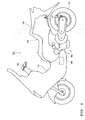
- Fig. 1 is a left side elevational view of a scooter type hybrid motorcycle which is an example of the hybrid vehicle on which the drive unit for a hybrid vehicle according to an embodiment is mounted, showing the major part of the vehicle.
- the scooter type motorcycle of Fig. 1 is one of scooter type motorcycles that incorporate a series/parallel hybrid mechanism in which either one of an engine and an electric motor, both of which are power sources, individually drives a wheel, or both of the engine and the motor are combined to drive the wheel. More specifically, in the hybrid vehicle (called “scooter type motorcycle” below), a power dividing mechanism divides the engine power. A part of the divided power is used for directly driving the wheel, while the other part thereof is used for generating electric power. The usage ratio is controllable without any restraint. Additionally, the terms "front,” “forward,” “rear,” “rearward,” “left,” “right,” “top,” “upper,” “bottom” and “lower” in the embodiment are decided in accordance with directions of the rider's eyes.
- the scooter type motorcycle 100 of Fig. 1 has a vehicle body 103 supporting a handle bar 102 for pivotal movement on a front side of the vehicle body 103.
- a rear portion of the vehicle body 103 has a tandem seat 104 and a trunk space 105 disposed below the seat 104.
- a hybrid type drive unit 200 is positioned below the trunk space 105.
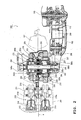
- Fig. 2 is a partial, plan cross sectional view of the drive unit 200 mounted on the scooter type motorcycle 100 of Fig. 1 which is one example of the hybrid vehicle, schematically showing the structure of the drive unit 200.
- the drive unit 200 includes an engine 210, an electric motor 230, a power distributing device 250 and a generator 270.
- the motor 230, the power distributing device 250 and the generator 270 are aligned on a power transmitting shaft 280 extending parallel to a crankshaft 211 of the engine 210 and positioned in the rear of the crankshaft 211.
- respective bearings 280a-280e in a housing 201 journal the power transmitting shaft 280 for rotation.
- the engine 210 in this embodiment is a two-cylinder engine, and is disposed below the trunk space 105 of the scooter type motorcycle 100.
- respective axes of two cylinders 212 of the engine 210 extend parallel to a vehicle center axis A(corresponding to a perpendicular plane extending through a center of a rear wheel in a transverse direction), and the axes are symmetrically positioned relative to the plane including the center axis A.
- the engine 210 has equal ignition intervals (crank angle 720 degrees per number of cylinders). Torque fluctuations of the crankshaft 211 of the engine 210 thus can be reduced. Additionally, the number of cylinders and the type of the engine are not limited to this embodiment. For example, the engine can have a single cylinder, or three or more cylinders. Also, a V-type engine, a horizontal opposed type engine, etc. can apply other than the in-line type engine.
- a piston 215 disposed in each cylinder 212 is connected to the crankshaft.211 extending generally in the transverse direction through a connecting rod 216 which rod body extends in a fore to aft direction of the vehicle. Because of this arrangement, the crankshaft 211 rotates together with reciprocal movement of the respective pistons 215. The engine 210 thus operates. Also, under a standstill condition of the engine 210, the respective pistons 215 can start moving reciprocally by the crankshaft 211 rotated. The engine 210 itself thus starts operating.
- the crankshaft 211 has a crank gear (rotary member) 218 positioned between large ends 216a of respective connecting rods 216 connected to the two pistons 215 to transmit the rotational force of the crankshaft 211 to the power transmitting shaft 280 of the power distributing device 250.
- the crank gear 218 is placed generally at a center of the crankshaft 211 in its axial direction.
- Fig. 3 is a perspective exploded view of the drive unit 200 of Fig. 2, showing the major part thereof.
- Fig. 4 is an enlarged perspective view of an engine power transmitting line that transmits the engine power to the power transmitting shaft 280 from the crankshaft 211 in Fig. 3.
- the crank gear 218 engages with an intermediate gear 220 (transmitting section) which rotates about an axis extending parallel to the axis of the crankshaft 211.
- the intermediate gear 220 engages with gear teeth 252a formed on an outer circumferential portion of a planetary gear carrier 252 of the power distributing device 250.
- the intermediate gear 220, together with the crank gear 218, functions as a power transmitting section that takes the engine power out generally at the center of the crankshaft 211 in the transverse direction and transmits the power to the power distributing device 250.
- the intermediate gear 220 together with the crank gear 218, forms the engine power transmitting line that transmits the power of the engine 210 to the power distributing device 250.
- the engine power transmitting line formed with the crank gear 218, the intermediate gear 220 and the planetary gear carrier 252 are offset from the vehicle center axis A opposite to a location where an arm section 202 of the drive unit 200 is positioned.
- the intermediate gear 220 is positioned to be rotatable between the crankshaft 211 and the power transmitting shaft 280 and about an axis of an intermediate gear shaft 220a extending parallel to both of the crankshaft 211 and the power transmitting shaft 280.
- the intermediate gear shaft 220a is placed below both of the crankshaft 211 and the power transmitting shaft 280.
- the intermediate gear 220 thus engages with the crank gear 218 at a front upper portion 220b of its outer circumferential portion and also engages with the gear teeth 252a of the outer circumferential portion of the planetary gear carrier 252 at a rear upper portion 220b of its outer circumferential portion.
- the intermediate gear 220 has a main gear section 221 rotatable about the axis of the intermediate gear shaft 220a and a pair of side gear sections 222 and 223 attached to the main gear section 221 on respective lateral sides thereof and rotatable in their circumferential directions.
- the main gear section 221 engages with the crank gear 218 and the planetary gear carrier 252 at the front upper portion of the outer circumferential portion and at the rear upper portion thereof, respectively.
- the respective side gear sections 222 and 223 are coaxially positioned with the main gear section 221 for rotation.
- Each side gear section 222, 223 has an outer diameter that is the same as the main gear section 221.
- An outer circumferential portion of each side gear section 222, 223 has teeth which number is different from that of the main gear section 221.
- the number of the teeth of the side gear section 222 is less than the number of the teeth of the main gear section 221, while the number of the teeth of the side gear section 223 is greater than the number of the teeth of the main gear section 221.
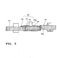
- Fig. 5 is a plan view of the engine power transmitting line including the intermediate gear.
- the main gear section 221 and the side gear section 222 together engage with the crank gear 218, while the main gear section 221 and the other side gear section 223 together engage with the planetary gear carrier 252.
- the backlash between the crank gear 218 and the intermediate gear 220 is adjusted.
- the backlash between the intermediate gear 220 and the planetary gear carrier 252 is adjusted.
- any possible backlashes between the crank gear 218 and the intermediate gear 220 and between the intermediate gear 220 and the planetary gear carrier 252 can be prevented from occurring by the structure of the intermediate gear 220.
- the main gear section 221 has balance weights 225 in the inner space thereof to make the weight allotment of the section 221 disproportion.
- the balance weights 225 cancel the reciprocal inertia made by the movement of the pistons of the engine 210. More specifically, each balance weight 225 is offset from an axis of the main gear section 221, i.e., from the intermediate gear shaft 220a. In this embodiment, each balance weight 225 is positioned at a location most spaced apart from the pistons 215 when the pistons 215 are positioned at the top dead center of the respective cylinders. Additionally, a counter weight (not shown) of the crankshaft 211 is also positioned at a location most spaced apart from the pistons 215 when the pistons 215 are positioned at the top dead center.
- each balance weight 225 has a portion extending in the inner space of the main gear section 221 along a part of the outer circumference and protruding in the transverse direction.
- Each portion protruding in the transverse direction and extending along the part of the outer circumference is a portion of a guide which guides the associated side gear section 222 or 223 when the section 222 or 223 rotates about the axis of the intermediate gear shaft 220a. That is, each of the circular side gear sections 222 and 223 fits on the associated portion, which extends along the outer circumference, for rotation.
- the crankshaft 211 is connected to the power distributing device 250 through the intermediate gear 220 so that the rotational force of the crankshaft 211 is transmitted to the power distributing device 250. Conversely, the drive force of the power distributing device 250 can be transmitted to the crankshaft 211 through the intermediate gear 220.
- the intermediate gear 220 is provided as an intermediate transmitting member that transmits the engine power to the planetary gear carrier 252 of the power distributing device 250 from the crankshaft 211.
- the intermediate transmitting member is not limited to the intermediate gear 220.
- a chain or a belt such as a V-shaped belt or a toothed belt can replace the intermediate gear 220 to transmit the rotational force of the crankshaft 211 to the power distributing device 250.
- the power distributing device 250 to which the engine power is transmitted from an outer circumference of the device 250 through the intermediate gear 220 is disposed on the power transmitting shaft 280 between the motor 230 and the generator 270.
- the power distributing device 250 has, other than the planetary gear carrier 252, a sun gear 254, planetary gears 256 and a ring gear 258.
- Those gears 254, 256, 258 have their own shafts extending parallel to each other and are rotatable about axes of the respective shafts together with the planetary gear carrier 252.
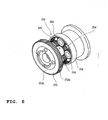
- Figs. 6 and 7 are perspective exploded views of the power distributing device 250, showing the major part thereof. More specifically, Fig. 6 is an exploded view of the power distributing device 250 without the planetary gear carrier 252, showing the major part of the device 250 viewed from the generator side (i.e., the right side of the vehicle), while Fig. 7 is an exploded view of the power distributing device 250 in a state that the ring gear 258 is removed from the sun gear 254, showing the device 250 viewed from the motor side (i.e., the left side of the vehicle).
- the power distributing device 250 properly distributes the drive power transmitted from the engine 210 between the vehicle driving force that directly drives the rear wheel 107 through a rear wheel drive force transmitting line located in the interior of the arm section 202 and the generator driving force that makes the generator 270 generate electric power.
- the power distributing device 250 can transmit the drive force of the motor 230 to the crankshaft 211.
- the power of the engine 210 is transmitted to the gear teeth 252a of the outer circumferential portion of the planetary gear carrier 252 through the intermediate gear 220.
- the outer circumferential portion having the gear teeth 252a has a cylindrical shape protruding on one side, i.e., toward the motor 230 from an outer periphery of a circular carrier body 252b. That is, the gear teeth 252a overhangs relative to the carrier body 252b.
- the carrier body 252b adjoins the sun gear 254 formed on an outer circumferential surface of the power transmitting shaft 280, and is positioned on the power transmitting shaft 280 for rotation about an axis of the power transmitting shaft 280.
- the planetary gear carrier 252 has a plurality of planetary pins 252c (see Figs. 2 through 4) protruding from one side of the carrier body 252b and extending parallel to the power transmitting shaft 280 that is inserted into the carrier body 252b.
- the planetary pins 252c are positioned inside of the outer circumferential portion of the carrier body 252b that has the gear teeth 252a, and are placed coaxially about the axis of the power transmitting shaft 280 so as to be spaced apart from each other at equal intervals.
- the planetary pins 252c are positioned around the sun gear 254 to journal the planetary gears 256 engaging with the sun gear 254 for rotation (see Figs. 2 and 7).
- a come-off preventing member 252d is attached to distal ends of the respective planetary pins 252c that are inserted into the associated planetary gears 256 to prevent the planetary gears 256 from coming off from the respective planetary pins 252c (see Fig. 7).
- the planetary gears 256 revolve around the sun gear 254 while rotating.
- the sun gear 254 is formed on a part of the outer circumference of the power transmitting shaft 280.
- the power transmitting shaft 280 is formed in such a manner that a shaft portion of a rotor 271 of the generator 270 disposed on the side opposite to the motor 230 relative to the power distributing device 250 is axially elongated in the transverse direction. As shown in Fig. 2, the power transmitting shaft 280 is inserted from one side end of the vehicle (i.e., right side in this embodiment). A distal end of the shaft 280 on the other side end of the vehicle is inserted into the rotor 231 of the motor 230 for rotation.
- the sun gear 254 is unitarily formed with the power transmitting shaft 280 that is the extended shaft portion of the rotor 271 of the generator 270, the rotor 271 rotates together with the rotation of the sun gear 254. In other words, the generator 270 rotates together with the rotation of the sun gear 254. Conversely, the sun gear 254 rotates together with the rotation of the generator 270.
- the ring gear 258 is disposed along the outer circumferences of the respective planetary gears 256 so that the inner circumferential surface of the ring gear 258 engages with the respective planetary gears 256.
- the ring gear 258 is joined with the rotor 231 of the motor 230.
- the rotor 231 thus rotates about an axis of the rotor 231 together with the ring gear 258 rotating about the axis of the power transmitting shaft 280 to generate the vehicle thrusting force.
- Fig. 8 is a perspective exploded view of the major part, indicating a coupling relationship between the ring gear 258 and the rotor 231 of the motor 230.
- the ring gear 258 has a circular body 258a and a cylindrical outer circumferential rib 258b.
- the circular body 258a has a central aperture into which the power transmitting shaft 280 (see Figs. 2, 3, 6 and 7) is inserted.
- the outer circumferential rib 258b extends perpendicularly relative to the circular body 258a from the outer periphery of the circular body 258a.
- the outer circumferential rib 258b has an inner circumferential surface extending circumferentially and forming gear teeth 258c which engage with the planetary gears 256 (see Figs. 2 through 4, 6 and 7).
- the outer circumferential rib 258b surrounds the planetary gears 256 while disposed inside of the cylindrical outer circumferential portion of the planetary gear carrier 252 which has the gear teeth 252a on its outer circumferential surface. That is, the outer circumferential portion of the planetary gear carrier 252 surrounds the ring gear 258.
- the outer circumferential rib 258b is positioned between the gear teeth 252a of the planetary gear carrier 252 and the planetary gears 256 journaled by the planetary gear carrier 252 so that the gear teeth 258c formed on an inner circumferential surface of the rib 258b engage with the planetary gears 256.
- the ring gear 258 is positioned at the same location as the planetary gear carrier 252 in an axial direction of the power transmitting shaft 280.
- the occupied space by the planetary gear carrier 252 and the ring gear 258 can be smaller in the transverse direction of the vehicle to the extent that both of them overlap with each other, i.e., to the extent that the outer circumferential portion having the gear teeth 252a overhangs, in comparison with the structure in which both of them are juxtaposed on the power transmitting shaft 280 without the overlap.
- the outer periphery of the circular body 258a of the ring gear 258 has a plurality of openings 258d which axially open and neighbor each other in the circumferential direction.
- the rotor 231 of the motor 230 has a plurality of projections 232.
- the projections 232 are inserted into the openings 258d in the axial direction of the ring gear 258 and from a surface (left surface relative to the vehicle) which is the reverse surface of the other surface (right surface relative to the vehicle) where the outer circumferential rib 258b extends.
- the planetary pins 252c unitarily formed with the planetary gear carrier 252 rotate about the axis of the power transmitting shaft 280.
- the planetary gears 256 rotate to revolve around the sun gear 254.
- the sun gear 254 and the ring gears 258 together rotate because they engage with the planetary gears 256.
- the sun gear 254 is unitarily formed with the rotor 271 of the generator 270, the rotor 271 rotates together with the sun gear 254 to drive the generator 270 for generating the electric power.
- the generator 270 generates the electric power because of the rotation of the rotor 271 which is the part of the power transmitting shaft 280 and supplies the generated power to a battery 400 (see Fig. 1) and the motor 300.
- the generator 270 can function as a motor operated by the power of the battery in addition to functioning as the generator.
- the generator can operate as a starter motor that starts the engine 210 when a charge amount of the battery is less than a preset amount.
- the motor 230 can function as a motor that generates resistance force restraining the rotation of the axel 110 when the motorcycle 100 is decelerated or braked.
- the battery 400 (see Fig. 1) is electrically connected to the generator 270 driven by the engine 210.
- the battery 400 supplies the electric power to the motor 230 for operation and accumulates the power generated by the motor 230 and the generator 270.
- a rotational shaft of the motor 230 has a common axis together with the power transmitting shaft 280.
- the motor 230 is juxtaposed with the generator 270 and the power distributing device 250 in the transverse direction to be positioned in front of the rear wheel 107.
- the motor 230 has a stator 233 (see Figs. 2 and 3) fixed inside of the housing 201 (see Fig. 2) of the drive unit 200, and the rotor 231 located inside of the stator 233 to be rotatable about the axis of the power transmitting shaft 280.
- the rotor 231 has a cylindrical rotor body 231 a.
- the multiple projections 232 which are inserted into the respective openings of the ring gear 258, extend from one opening side end of the rotor body 231 a. Because the projections 232 are inserted into the openings 258d of the ring gear 258, the ring gear 258 and the rotor 231 are joined together.
- the ring gear 258 also rotates about the axis of the power transmitting shaft 280.
- the rotor 231 is coupled with a sprocket 284 provided on the other side of the vehicle (left side) to transmit the rotational force to the rear wheel 107. That is, the drive force of the motor 230 caused by the electric power of the battery 400 is transmitted to the rear wheel 107 through the sprocket 284 rotating together with the rotation of the rotor 231. Also, the power of the engine 210 is transmitted to the rear wheel 107 through the rotor 231 rotating with the rotation of the ring gear 258 and the sprocket 284.
- the sprocket 284 takes out the power of the engine or the drive force of the motor through the motor 230 (specifically, the rotor 231) positioned on the one end of the power transmitting shaft 280 to properly reduce the rotational speed before the power or the drive force is transmitted to the rear wheel 107. Additionally, the sprocket 284 is placed at a position 282 next to the one end of the power transmitting shaft 280 to be rotatable about the axis of the power transmitting shaft 280.
- a chain 287 is wound around the sprocket 284 and a sprocket of a speed reduction gear section 286 disposed in the rear of the sprocket 284.
- Another chain 289 is wound around another sprocket of the speed reduction gear section 286 and a sprocket 112 of the axle 110 disposed in the rear of the sprocket of the speed reduction gear section 286.
- the drive force transmitted to the speed reduction gear section 286 through the chain 287 is transmitted to the axle 110 to drive the rear wheel 107.
- the sprocket 284, the chain 287, the speed reduction gear section 286, the sprocket 112, the chain 289 and the sprocket 112 of the axle 110 together form the rear wheel drive force transmitting line to rotate the rear wheel 107 or drive wheel.
- the rear wheel drive force transmitting line is arranged in the interior of the cantilevered arm section 202 of the drive unit 200 positioned on the left side of the rear wheel 107 (see Fig. 2).
- the rear wheel drive force transmitting line is placed adjacent to the motor 230.
- a distance between the motor 230 and the sprocket 284 of the rear wheel drive force transmitting line is short.
- the rotational force of the motor 230 thus can be directly transmitted to the sprocket 284.
- the drive unit 200 does not need any additional linkage members linking the motor 230 and the sprocket 284 to each other. Because the rotor 231 is directly connected to the sprocket 284 in this embodiment, the drive unit 200 is hardly affected by the torsional vibrations caused by the rotational torque of the motor 230.
- the rear wheel drive force transmitting line interposes the vehicle center axis A together with the engine power transmitting line in the transverse direction of the drive unit 200, and is positioned on the side opposite to the engine power transmitting line relative to the center axis A. That is, the engine power transmitting line is offset to the opposite side of the arm section 202 of the drive unit 200 relative to the center line A.
- the scooter type motorcycle 100 having the drive unit 200 as thus constructed, at least the drive force of the motor 230, or both of the power of the engine 210 provided through the power distributing device 250 and the drive force of the motor 230 drive the rear wheel 107.
- the power of the engine 210 is inputted to the power distributing device 250 from the outer circumference of the planetary gear carrier 252 through the crank gear 218 and the intermediate gear 220 both forming the engine power transmitting line.
- the power inputted to the power distributing device 250 is transmitted to the rotor 231 by the rotation of the ring gear 258 following the rotation of the planetary gears 252 and is inputted to the sprocket 284 of the rear wheel drive power transmitting line positioned in the interior of the arm section 202 from the rotor 231.
- the power is then transmitted to the rear wheel 107 through the rear wheel drive force transmitting line so that the rear wheel 107 is driven.
- the operations of the engine 210 and the motor 230 i.e., the operation of the drive unit 200, are decided in accordance with the running conditions of the scooter type motorcycle 100 or the charge amount of the battery 400 (see Fig. 1) to which the electric power for the operation of the motor 230 is charged.
- the drive unit 200 operates in response to the running condition of the vehicle or the charge amount of the battery 400.
- the scooter type motorcycle 100 starts and runs using only the drive force of the motor 230. Because the charge amount of the battery 400 is greater than the preset amount in the states, the generator does not need to generate the electric power. The engine 210 is at standstill, accordingly.
- the operation of the motor 230 rotates the rotor 231, and the sprocket 284 rotates with the rotation of the rotor 231. Together with the rotation of the sprocket 284, the speed reduction gear section 286 rotates via the chain 287, and the rear wheel 107 rotates via the chain 289 and the axle 110.
- the ring gear 258 rotates.
- the respective planetary gears 256 rotate in the same direction as the ring gear 258.
- the sun gear 254 rotates in the reverse direction relative to the planetary gears 256.
- cranking means the state in which the rotational force is given to the crankshaft from outside to make the pistons 215 reciprocally move.
- the respective planetary gears 256 rotate and also the planetary pins 252c revolve around the sun gear 254.
- This revolution (corresponding to the rotation of the planetary gears) is transmitted to the crankshaft 211 through the planetary pins 252c, specifically, the planetary gear carrier 252.
- the crankshaft 211 thus can rotate to drive the pistons 215 through the connecting rods 216.
- the rotor 271 of the generator 270 i.e., the sun gear 254 is rotated synchronously with the motor 230 (i.e., the ring gear 258) at the same rotational speed. This is achieved when the speeds of the rotor 271 and the sun gear 254 are synchronized with the speed of the motor 230 by which the speed of the generator 270 is controlled.
- the planetary gear carrier 252 itself does not rotate.
- the rotational force is not transmitted to the crankshaft 211, and the cranking of the engine 210 is prevented in the starting state and the light load running state.
- the scooter type motorcycle 100 runs using the power of the engine 210 and the drive force of the motor 230 so that the vehicle can run in an operational range where the engine 210 has a suitable fuel consumption rate.
- the power distributing device 250 properly distributes the power of the engine 210 between the vehicle driving force that directly drives the rear wheel 107 and the generator driving force that makes the generator 270 generate the electric power. That is, the engine 210 outputs both of the vehicle driving force and the drive force of the motor 230 made by the electric power generated by the generator 270 using the generator driving force.
- the power of the engine 210 rotates the planetary gear carrier 252 through the intermediate gear 220. That is, because of the rotation of the crankshaft 211 of the engine 210, the respective planetary pins 252c revolve about the axis of the power transmitting shaft 280. Together with the revolution of the planetary pins 252c, the respective planetary gears 256 revolve about the axis of the power transmitting shaft 280 and around the sun gear 254 while rotating around the associated planetary pins 252c.
- the ring gear 258 rotates. Together with the rotation of the ring gear 258, the rotor 231 of the motor 230 rotates to drive the sprocket 284. The rotation of the sprocket 284 is transmitted to the axle 110 through the chain 287, the speed reduction gear section 286 and the chain 289 to rotate the rear wheel 107.
- the generator 270 Because of the rotation of the rotor 271, the generator 270 generates the electric power.
- the electric power of the generator 270 is supplied to the motor 230 for its rotation.
- the motor 230 thus rotates to drive the rear wheel 107 through the rear wheel drive force transmitting line including the sprocket 284.
- the scooter type motorcycle 100 increases the speed of the engine 210 and supplies the electric power accumulated in the battery 400 together with the generated power to the motor 230, in addition to the operations in the ⁇ normal running state>.
- the motor 230 receiving such electric power outputs more powerful drive force. That is, in addition to the power of the engine 210, the drive force of the motor 230 rotates the rotor 231. The rotational force of the rotor 231. is transmitted to the rear wheel drive force transmitting line to rotate the rear wheel 107.
- the scooter type motorcycle 100 uses the engine brake action of the engine 210. That is, the rotation of the axle 110 of the rear wheel 107 is transmitted to the engine 210 through the engine power transmitting line, the rotor 231 of the motor 230 and the power distributing device 250 to reciprocally move the pistons 215 of the engine 210. Under this condition, the friction and the compression resistance force generated together with the reciprocal movement of the pistons 215, i.e., the so-called engine brake acts in the engine 210.
- the rotational speed of the rotor 271 temporarily increases to the extent in which the over rotation does not occur to increase the speed of the engine 210 through the power distributing device 250.
- the engine 210 having the increased engine speed generates the engine brake action; thereby, the scooter type motorcycle 100 decelerates or brakes.
- the electric power accumulated in the battery 400 (see Fig. 1) is supplied to the generator 270 so that the generator 270 works as a motor to start the engine by the rotational force thereof.
- the engine 210 drives the generator 270 through the power distributing device 250.
- the electric power generated by the operation of the generator 270 is charged into the battery 400 or is supplied to the motor 230.
- the generator 270 is powered to rotate and to function as a starter motor. Together with the rotation of the generator 270, the sun gear 254 rotates. In the idling state, the scooter type motorcycle 100 does not move and the ring gear 258 does not rotate.
- the respective planetary gears 256 engaging with the sun gear 254 revolve around the sun gear 254 while rotating. Accordingly, the planetary gear carrier 252 rotates about the axis of the power transmitting shaft 280 via the planetary pins 25 supporting the planetary gears 256. The rotation of the planetary gear carrier 252 is transmitted to the crankshaft 211 through the intermediate gear 220 to start the engine 210.
- the rotational force of the planetary gears 256 is transmitted to the sun gear 254.
- the sun gear 254 rotates in the reverse direction relative to the planetary gears 256.
- the rotation of the sun gear 254 rotates the rotor 271, and the generator 270 generates the electric power.
- the electric power is accumulated in the battery 400.
- the motor 230 is supplied with the electric power from the battery 400 or from the generator 270 to generate the drive force for keeping the axle 110 under the non-rotational condition to be given to the speed reduction gear section 286.
- the scooter type motorcycle 100 starts and runs using the drive force of the motor 230 while charging the battery 400 by the generator 270 that is operated by the engine 210.
- the motor 230 is driven to rotate the axle 110 through the rear wheel drive force transmitting line to start the scooter type motorcycle 100.
- the ring gear 258 rotates. Because of the rotation of this ring gear 258, the respective planetary gears 256 rotate, and the planetary gear carrier 252 rotates by the rotation of the planetary gears 256.
- the planetary gear carrier 252 is also driven by the engine 210 because the engine 210 still operates continuously from the foregoing ⁇ idling state>.
- the sun gear 254 rotates. Because the charge amount of the battery 400 (see Fig. 1) is less than the preset amount, the generator 270 generates the electric power for charging the battery 400.
- the scooter type motorcycle 100 In a normal running state, when the charge amount of the battery 400 is less than the preset amount, the scooter type motorcycle 100 operates in almost the same manner as operating when the charge amount of the battery 400 (see Fig. 1) is greater than the preset amount. However, before the charge amount of the battery 400 exceeds the preset amount, the electric power generated by the generator 270 is used for charging the battery 400 other than being used for driving the motor 230.
- the scooter type motorcycle 100 In a special running state such as the acceleration state or the hill climbing state which needs the higher output, the scooter type motorcycle 100 increases the speed of the engine 210 and supplies the electric power accumulated in the battery 400 together with the generated power to the motor 230, in addition to the operations of the drive unit 200 in the ⁇ normal running state>, to output more powerful drive force. However, the scooter type motorcycle 100 does not supply the electric power of the battery 400 to the motor 230 before the charge amount of the battery 400 exceeds the preset amount.
- the drive force of the-motor 230 made by the maximum amount of power that can be supplied by the generator 270 at this time and the vehicle driving force from the engine 210 are outputted to the rear wheel 107 before the charge amount of the battery 400 exceeds the preset amount.
- the rotation of the axle 110 is transmitted to the motor 230 through the speed reduction gear section 286 and the sprocket 284 in the scooter type motorcycle 100; thereby, the motor 230 rotates to act as a generator for regenerating the electric power.
- the kinetic energy in the vehicle deceleration state and the braking state is converted to the electric energy to be accumulated in the battery 400. That is, the scooter type motorcycle 100 decelerates or brakes because of the deceleration or braking action of the regenerative braking by the motor 230.
- the engine brake of the engine 210 is used for the minimum deceleration so as not to spoil the deceleration or braking action by the regenerative braking of the motor 230.
- the rotor 271 of the generator 270 is thus controlled within the limit where the rotor 271 does not overly rotate together with the rotor 231 of the engine 210.
- the scooter type motorcycle 100 having the drive unit 200 is provided with the crankshaft 211 extending in the transverse direction, i.e., extending normal to the center axis A of the vehicle and horizontally, and the power transmitting shaft 280 extending parallel to the crankshaft 211.
- the generator 270, the power distributing device 250 and the motor 230 are disposed on the power transmitting shaft 280.
- the power from the engine 210 is inputted into the power distributing device 250 positioned on the vehicle center axis A and between the generator 270 and the motor 230.
- the power of the engine 210 is transmitted to the generator 270, the motor 230 and the rear wheel 107 from the power distributing device 250. That is, the power of the engine 210 is inputted into the generally center portion of the power transmitting shaft 280 in the transverse direction on which the generator 270, the power distributing device 250 and the motor 230 are juxtaposed in the plan view to be rotatable about the same axis.
- the crankshaft 211 of the engine 210, the generator 270, the power distributing device 250 and the rotational shaft (i.e., the power transmitting shaft 280) of the motor 230 are not coaxially positioned.
- the total length of the shaft can be shorter in comparison with the conventional hybrid type drive unit in which the engine 210, the motor 230, and the generator 270 are disposed on a single shaft from the viewpoint that the rational power transmission is achieved. That is, the drive unit 200 in this embodiment, differently from the conventional unit, does not need to have such a length covering all the engine, the motor, the power distributing device and the generator disposed on the single shaft in the vehicle body of the hybrid vehicle.
- the shaft portion transmitting the power from the engine needs to be elongated at least for covering the length of the generator in the axial direction.
- a shaft member covering all of those devices cannot be neglected.
- a clutch device such as a relief clutch or a torsional vibration preventing device such as a torsional damper need to be attached to the shaft. That is, the conventional hybrid type drive unit having the power distributing device requires a device that prevents the torsional vibrations from acting on the shaft portion where the engine, the motor, the power distributing device and the generator are juxtaposed in line.
- the space covering the length of the torsional vibration preventing device is necessary as a mount space in addition to the space covering the lengths of the engine, the motor, the power distributing device and the generator. Accordingly, it was difficult to compactly mount the conventional hybrid type drive unit having the power distributing device and also including the power transmitting system coaxially disposed because the motorcycle only has.a quite limited space for mounting components.
- the drive unit 200 in this embodiment does not need to have the entire length covering the engine 210, the motor 230, the power distributing device 250 and the generator 270 which can be juxtaposed in line in the vehicle body on which the drive unit 200 is mounted.
- the motorcycle which has only the limited space can allow those components to be compactly mounted. That is, in the scooter type motorcycle 100, the engine 210, the motor 230, the power distributing device 250 and the generator 270 are compactly disposed in the limited space below the seat.
- the power of the engine 210 is outputted from the portion of the crankshaft 211 adjacent to the center thereof in the transverse direction to the portion of the power transmitting shaft 280 adjacent to the center thereof along the vehicle center axis A.
- the engine power is transmitted from the crankshaft 211 through the intermediate gear 220 to be inputted to the power distributing device 250 positioned generally at the center of the power transmitting shaft 280, on which the generator 270, the power distributing device 250 and the motor 230 are disposed in this order, from the outer circumference of the planetary gear carrier 252. Accordingly, there is no need to additionally provide any device that can receive the drive force of the crankshaft 211 to output it to the power distributing device 250 on the power transmitting shaft 280, which is the different shaft different from the crankshaft 211 and on which the generator 270, the power distributing device 250 and the motor 230 are disposed. More compact structure is thus realized.
- the engine power transmitting line transmitting the power of the engine 210 to the power transmitting shaft 280 is offset toward the opposite side to the side having the rear wheel drive force transmitting line relative to the perpendicular plane including the vehicle center axis A.
- the drive power transmitting system of the scooter type motorcycle 100 is well balanced between the right and left sides.
- the shaft portion of the rotor 271 of the generator 270 is elongated to form the power transmitting shaft 280 on which the power distributing device 250 and the motor 230 are disposed.
- the ring gear 258 of the power distributing device 250 and the rotor 231 of the motor 230 are coupled with each other around the power transmitting shaft 280.
- the shaft member extending through the motor 230, the power distributing device 250 and the generator 270 is the portion of the power transmitting shaft which is the elongated shaft portion of the rotor 271 of the generator 270. That is, differently from the hybrid type drive unit having the conventional power distributing device, in order to make a rational power transmission, there is no need to provide any additional shaft in the shaft portion of the generator for transmitting the engine power.
- the power transmitting shaft 280 which is the different shaft from the crankshaft 211, can have an outer diameter that is the size with which the shaft can endure against the torsional vibrations generated by the torque fluctuations of the engine operation.
- the power transmitting shaft 280 thus does not resonate with the engine vibrations.
- the drive unit 200 does not require any clutch device or torsional vibration preventing device to prevent the torsional vibrations from occurring at the shaft of the drive power transmitting system by the resonance of the engine vibrations.
- the drive unit thus can be compact to this extent.
- the scooter type motorcycle 100 does not need any clutch mechanism that can connect or disconnect the power transmission or make the power transmission slip, or any torsional damper that can absorb or attenuate the torque fluctuations of the engine 210, in the rotational force transmitting path to the power distributing device 250 from the crankshaft 211.
- the drive unit 200 of the scooter type motorcycle 100 has the intermediate gear 220 between the crankshaft 211 and the planetary gear carrier 252 on the power transmitting shaft 280 as the structure through which the engine power is transmitted to the power transmitting shaft 280 from the crankshaft 211.
- the position of the intermediate gear 220 and the reduction ratio can be freely changed without changing the positions or the outer diameters of the crankshaft 211 and the power transmitting shaft 280.
- the primary reduction ratio that can maintain the engine performance, the generator performance, the motor performance, and the vehicle performance of the hybrid type drive unit in a suitable balance can be properly and easily set.
- the engine power is transmitted to the power distributing device 250 from the crankshaft 211 through the intermediate gear 220.
- the structure of the drive unit 200 is more compact than another structure in which the crank gear 218 and the gear teeth 252a of the outer circumference of the planetary gear carrier 252 directly engage with each other.
- the crank gear 218 and the planetary gear carrier directly engage with each other in the structure of the drive unit, at least either one of the crank gear that has an outer diameter larger than the outer diameter of the counter weight of the crankshaft and the planetary gear carrier that has an outer diameter larger than the outer circumference of the motor is necessary.
- the possible drive unit is inevitably larger than the drive unit 200 in this embodiment that has the intermediate gear 220.
- the intermediate gear 220 linking the crank gear 218 of the crankshaft 211 and the power distributing device 250 can be separately changed after being assembled. Accordingly, the structure can be more easily assembled or disassembled than another structure in which a chain is used for transmission. That is, if the chain is used, a tension adjusting mechanism is necessary to loosen or tighten the chain while the chain is attached and can increase the man hour for assembling.
- the intermediate gear shaft 220a of the intermediate gear 220 having the balance weights 225 is positioned below the crankshaft 211 and the power transmitting shaft 280.
- the location needs to be a position X (see Fig. 1) which is positioned in a front area of the drive unit 200 and adjacent to bottom ends of the respective cylinders.
- the balance weight(s) disposed at the position X indicated in Fig. 1 does not hinder positioning of an exhaust pipe of the engine, which is not shown. This is convenient because such another balance weight(s) disposed in the drive. unit 200 in addition to the balance weights 225 can contribute to more efficient cancellation of the reciprocal inertia caused by the pistons of the engine 210.
- the hybrid type drive unit 200 having the power transmitting device 250 is disposed below the seat of the motorcycle. Specifically, the drive unit 200 is efficiently disposed in the limited space below the tandem seat 104 and the trunk space 105 (see Fig. 1). Thus, in the motorcycle, the drive unit 200 does not affect other components other than the drive system. The drive unit 200 thus can allow the rider to have various riding positions and can give wide varieties of possible external designs.
- the drive unit 200 of this embodiment is mounted on the series-parallel type and scooter type motorcycle 100.
- this invention is not limited to the drive unit.
- the drive unit having the structure in which the generator, the motor and the power distributing device are disposed on the shaft different from the crankshaft of the engine and parallel to the crankshaft can be mounted on a parallel type hybrid vehicle.
- a drive unit for a hybrid vehicle includes an engine; a generator generating electric power by an operation of the engine; an electric motor driven by the electric power of the generator to rotate a drive wheel; and a power distributing device distributing the drive power generated by the engine between the generator and the drive wheel, in which the generator, the motor and the power distributing device are disposed on a single different shaft ("separate shaft") which is different from a crankshaft of the engine and extends parallel to the crankshaft.
- the generator, the motor and the power distributing device are not juxtaposed with the crankshaft, because the generator, the motor and the power distributing device are disposed on the single different shaft which is different from the crankshaft of the engine and extends parallel to the crankshaft. That is, the structure including the engine, the generator, the motor, and the power distributing device does not elongate and can be compact enough.
- the generator, the engine and the motor can be mounted without protruding in the transverse direction.
- the drive unit thus can be suitably and easily mounted on a vehicle, e.g., a motorcycle, which only has such a limited space.
- the drive unit can be mounted on a vehicle, e.g., a motorcycle which only has such a limited space without greatly protruding in the transverse direction even though the drive unit has the power distributing mechanism.
- the present structure can avoid the torsional vibrations occurring in the power transmitting shaft in the conventional structure when the torque fluctuations of the crankshaft in the engine output is transmitted to the drive unit.
- the crankshaft of the engine extends horizontally and normal to a direction in which the vehicle advances.
- the single shaft different from the crankshaft extends normal to the direction in which the vehicle advances and horizontally.
- a motorcycle having a limited mount space for the drive unit can have the hybrid type drive unit with no portion of the drive unit protruding in the transverse direction.
- both of the crankshaft and the different shaft extend in the transverse direction, the power of the engine and the drive force of the motor both outputted from the different shaft can be transmitted to the axle which is disposed in the transverse direction and journals the rear wheel in a simple structure.
- the different shaft is positioned in the rear of the crankshaft of the engine.
- the axle of the drive wheel can be easily positioned in the rear of the different shaft, and the hybrid vehicle in which the rear wheel is the drive wheel can be easily realized.
- the drive unit for a hybrid vehicle further including an axle of the drive wheel spaced apart from the different shaft to extend parallel thereto; and a drive force transmitting device extending normal to the different shaft, and taking out the drive power of the motor and the drive power of the engine from one end of the different shaft to transmit the respective drive powers to the axle, in which the motor is disposed on the one end of the different shaft.
- the drive force of the motor can be directly transmitted to the drive force transmitting device. That is, the length of the member that transmits the drive force, i.e., the rotational force of the rotor of the motor, to the drive force transmitting device can be shorter. The resonance caused by the torque vibrations occurring in the engine operation can be mostly avoided.
- the drive force transmitting device includes a reducing section reducing the drive power taken out from the one end.
- the drive power taken out from the one end can be properly reduced before the drive power is transmitted to the drive wheel.
- the reducing section can be disposed at one end of the different shaft to rotate about the axis of the different shaft so as to reduce the drive force outputted from the one end.
- the reducing section can be positioned between the one end of the different shaft and the axle.
- the drive unit for a hybrid vehicle further including an engine power transmitting section taking out the power generated by the engine from a generally center portion of the crankshaft in the axial direction thereof to transmit the power to the power distributing device, in which the power distributing device is disposed on the different shaft and between the generator and the motor.
- the engine power transmitted to the power distributing device from the crankshaft can be transmitted generally in the center portion of the vehicle, on which the drive unit is mounted, in the transverse direction.
- the shaft portion which generates the vibrations in the engine operation can be shortest.
- the different shaft is coupled with a rotor of the generator
- the power distributing device includes: a sun gear disposed on the different shaft and rotating together with the different shaft about a common axis of the different shaft and the sun gear; a planetary gear positioned around the sun gear to engage with the sun gear; a planetary gear carrier positioned around the different shaft for rotation to support the planetary gear for rotation; and a ring gear positioned around the planetary gear to engage with the planetary gear and positioned around the different shaft for rotation to output rotational force of the different shaft to the drive wheel, in which the planetary gear carrier has an outer circumferential portion connected to the engine power transmitting section and rotating around the different shaft, and the planetary gear revolves around the sun gear using the power of the engine inputted from the outer circumferential portion through the engine power transmitting section.
- the power distributing device disposed on the different shaft and positioned at the generally center portion in the transverse direction between the motor and the generator is the planetary gear mechanism.
- the engine power is inputted from the outer circumferential portion of the planetary gear carrier through the engine power transmitting section.
- the engine power transmitted to the power distributing device from the crankshaft can be inputted to the power distributing device from the generally center portion of the different shaft in the transverse direction through the engine power transmitting section without rotating the planetary gear carrier by being inputted from an end of the different shaft.
- the so-called center-take-off type structure in which the engine power is taken from the generally center portion of the crankshaft in the transverse direction though the engine power transmitting section can be realized.
- the hybrid type drive unit thus can be compactly formed.
- the ring gear is directly coupled with a rotor of the motor rotating about a common axis of the ring gear and the rotor of the motor, and the ring gear outputs rotational force thereof to the drive wheel through the rotor of the motor.
- the length of the power distributing device in the axial direction can be shorter.
- the entire length of the motor, the power distributing device and the generator in the axial direction can be shorter.
- the entire length of the drive power unit having the crankshaft extending in the transverse direction and horizontally can be shorter in the transverse direction.
- the motorcycle which has the narrow width thus can easily have the drive unit.
- the engine power transmitting section includes a rotary member synchronously rotating with the rotation of the crankshaft, and a transferring section transferring rotational force of the rotary member to the outer circumferential portion of the planetary gear carrier.
- the rotary member and the transferring section can rotate the planetary gear carrier.
- the engine power thus can be transferred to the power distributing device from the crankshaft in such a simple structure.
- both of them can have gear teeth engaging with each other, and the planetary gear carrier can have gear teeth on its outer circumferential surface that engage with the gear teeth of the transferring section.
- the rotary member can be a sprocket, while the transferring section can be a chain, and the chain can be wound around the outer circumference of the planetary gear carrier.
- the planetary gear carrier can have multiple teeth that can engage with the chain on its outer circumferential surface.
- the rotary member can be a pulley, while the transferring section can be a belt wound around the pulley, which is the rotary member, and the outer circumference of the planetary gear carrier.
- respective outer circumferential portions of the rotary member and the planetary gear carrier have a plurality of gear teeth
- the transferring section is positioned between the rotary member and the planetary gear carrier to form an intermediate gear engaging with the respective gear teeth of the rotary member and the planetary gear carrier.
- the planetary gear carrier in the drive unit for a hybrid vehicle according to the construction described above, has a plate-like carrier body through which the different shaft extends and which supports the planetary gear, and the outer circumferential portion of the planetary gear carrier has a tubular shape protruding toward the ring gear from an outer periphery of the carrier body to surround the ring gear.
- the carrier body of the planetary gear carrier has the plate-like shape and the outer circumferential portion thereof surrounds the ring gear.
- the outer circumferential portion and the ring gear overlap with each other in the radial direction relative to the axis of the different shaft.
- the length of the power transmitting device in the axial direction thus can be shorter to the extent that the carrier body has the plate-like shape and also the outer circumferential portion and the ring gear overlap with each other. Accordingly, the total length of the motor, the power distributing device and generator in the axial direction on the different shaft can be shorter.
- the entire length of the drive force unit having the crankshaft extending in the transverse direction and horizontally can be shorter in the transverse direction.
- the drive unit thus can be mounted on the motorcycle which has such a narrow width.
- the drive unit for a hybrid vehicle further includes an axle extending parallel to the different shaft and the crankshaft, the axle being spaced apart from the different shaft and the crankshaft, the axle supporting the drive wheel; and a drive force transmitting device positioned at one end of the different shaft and taking out the drive power of the motor and the power of the engine to transmit the powers to the axle, in which the motor is positioned on the one end of the different shaft, and a line along which the power of the engine is transmitted to the power distributing device from the crankshaft through the engine power transmitting section is offset toward the other end of the different shaft from a perpendicular plane extending through a transverse center of the drive wheel.
- the line that transmits the engine power to the power distributing device which is disposed between the generator and the motor on the different shaft is offset toward the other end of the different shaft from the perpendicular plane extending through the transverse center of the drive wheel.
- the motor which axial size (width) is generally larger than that of the generator, is positioned at the one end of the shaft portion and the drive force transmitting device is also positioned at the one end of the shaft portion, the vehicle in which the drive unit having the line which transmits the engine power to the power distributing device from the crankshaft, particularly, the motorcycle, can be balanced in the transverse direction.
- the intermediate gear has an adjusting section adjusting a backlash between the intermediate gear and the rotary member and another backlash between the intermediate gear and the planetary gear carrier.
- the intermediate gear has a weight section offset from an axis of the intermediate gear and canceling the reciprocal inertia of the engine.
- the weight section of the intermediate gear can cancel the reciprocal inertia of the engine that inevitably occurs when the engine operates, i.e., when the pistons reciprocally move.
- the entire vibrations of the drive unit generated in the engine operation can decrease.
- the engine is a multi-cylinder engine, and ignitions are made at equal intervals among respective cylinders.
- the connecting rod of each cylinder is connected to the crankshaft for rotation at a balancing position between the one end and the other end of the crankshaft in the axial direction, as the center of the crankshaft in the axial direction being the reference point.
- the engine power i.e., the rotational force of the crankshaft is taken out from the generally center portion of the crankshaft, to which the connecting rods are connected, in the axial direction through the engine power transmitting section, as thus discussed, the torsional vibrations generated in the crankshaft of the engine can be effectively reduced.
- the hybrid vehicle has the drive unit described above.
- the hybrid vehicle can have the drive unit which is shortened and which includes the compactly made engine, generator, motor and power transmitting device in the narrow and limited mount space.
- the hybrid vehicle can be realized without increasing the manufacturing cost.
- the hybrid vehicle can allow the rider to have various riding positions and can give wide varieties of possible external designs.
- the motorcycle has the drive unit described above.
- the motorcycle can be the hybrid type vehicle that has the drive unit which is shortened and which includes the compactly made engine, generator, motor and power transmitting device in the narrow and limited mount space.
- the hybrid vehicle can be realized without increasing the manufacturing cost.
- the hybrid vehicle can allow the rider to have various riding positions and can give wide varieties of possible external designs.
- the drive unit for a hybrid vehicle provides the effect that, even though the crankshaft extends in the transverse direction, the generator, the engine and the motor can be suitably and easily mounted on the drive unit without protruding greatly. Consequently, the drive unit is useful for the motorcycle which only has such a limited mount space.
- a drive unit includes an engine 210; a generator 270 generating electric power by an operation of the engine 210; an electric motor 230 driven by the electric power of the generator 270 to rotate a drive wheel 107; and a power distributing device 250 distributing the drive power generated by the engine 210 between the generator 270 and the drive wheel 107.
- a crankshaft 211 of the engine 210 extends in a transverse direction of the vehicle.
- the generator 270, the motor 230 and the power distributing device 250 are disposed on a single different shaft which is different from the crankshaft 211 of the engine 210 and extends parallel to the crankshaft 211.
- the power of the engine 210 and the drive force of the motor 230 are outputted from one end of the different shaft through the power distributing device 250 and the rotor 231 of the motor 230.
Landscapes
- Engineering & Computer Science (AREA)
- Transportation (AREA)
- Mechanical Engineering (AREA)
- Chemical & Material Sciences (AREA)
- Combustion & Propulsion (AREA)
- Power Engineering (AREA)
- Electric Propulsion And Braking For Vehicles (AREA)
- Hybrid Electric Vehicles (AREA)
- Retarders (AREA)
- Arrangement Of Transmissions (AREA)
- Gears, Cams (AREA)
- Automatic Cycles, And Cycles In General (AREA)
Abstract
Description
- This invention relates to a drive unit for a hybrid vehicle (a hybrid type drive unit), including an engine and an electric motor both mounted on a vehicle and selectively used for driving a drive wheel, and a hybrid vehicle having this drive unit, particularly a hybrid type motorcycle.
- Conventionally, self-driving type vehicles such as motorcycles and automobiles typically have an engine for driving one or more wheels thereof. Recently, environmental issues have been regarded as important. It is thus desired to reduce carbon dioxide discharged from vehicles powered by an engine or to reduce substances which give rise to the pollution of the environment. Accordingly, developments are made in connection with vehicles having a drive motor which drives a wheel(s) together with an engine, i.e., the so-called hybrid vehicles.
- As a hybrid vehicle, there can be a parallel hybrid type vehicle in which a drive wheel(s) is driven by either one of an engine and a drive motor switched between them, in response to, for example, a running condition of the vehicle or a remaining power amount of a battery charged by a generator. In addition, there can be a series hybrid type vehicle in which an engine drives a generator to drive a drive motor for driving a drive wheel(s), using the electric power generated by the generator.
- In those vehicles, an example of a drive unit of the parallel hybrid type vehicles (particularly, four wheeled vehicles) is shown in
JP-A-2000-343964 - The drive unit disclosed in
JP-A-2000-343964 JP-A-2000-343964 - More specifically, in the drive unit of
JP-A-2000-343964 - In the meantime, it is desired that such a conventional hybrid type drive unit is mounted on a motorcycle. However, in the motorcycle, a mount space for the drive unit is limited to a portion of the vehicle body located between a front wheel and a rear wheel and below a seat. In addition, generally, a motorcycle has a narrower width than an automobile. The mount space thus can be further narrowed. Accordingly, it is extremely difficult to provide the motorcycle with the drive unit that has the arrangement in which the engine, the generator, the power distributing mechanism and the motor are arranged coaxially and in series so as to be rational in the viewpoint of the power transmission. As a result, no motorcycle on which the drive unit constructed as discussed above is efficiently mounted has been developed.
- This invention is made under the circumstances, and an object thereof is to provide a drive unit as indicated above that can be placed in a limited mount space of a motorcycle or the like without greatly protruding in the transverse direction even though the drive unit has a power distributing mechanism, and further to provide a hybrid vehicle or a motorcycle as indicated above which incorporates the drive unit.
- This objective is solved in an inventive manner by a drive unit for a hybrid vehicle comprising an engine, a generator generating electric power by an operation of the engine, an electric motor, and a power distributing device configured to distribute a drive power between the engine, the generator and the electric motor, wherein the generator, the motor, and said power distributing device are disposed on a separate shaft extending substantially in parallel to a crankshaft of the engine.
- Preferably, the drive unit for a hybrid vehicle comprises the engine, the generator generating electric power by the operation of said engine, the electric motor, which is driven by the electric power of said generator to rotate a drive wheel, and the power distributing device, which is distributing the drive power generated by said engine between said generator and said drive wheel, wherein said generator, said motor and said power distributing device are disposed on the single shaft which is different from the crankshaft of said engine and extends parallel to said crankshaft.
- Further, preferably the crankshaft of said engine extends horizontally and normal to a direction in which the vehicle advances.
- Still further, preferably said separate shaft is positioned in the rear of the crankshaft of said engine.
- According to a preferred embodiment, the separate shaft is a power transmitting shaft of the power distributing device.
- Beneficially, the drive unit for a hybrid vehicle further comprises an axle of said drive wheel, being spaced apart from said separate shaft to extend parallel thereto, and a drive force transmitting device extending normal to said separate shaft, and taking out the drive power of said motor and the drive power of said engine from one end of said separate shaft to transmit the respective drive powers to said axle, wherein said motor is disposed on said one end of said separate shaft.
- Therein, said drive force transmitting device may include a reducing section reducing the drive power taken out from said one end.
- Further, beneficially the drive unit for a hybrid vehicle further comprises an engine power transmitting section taking out the power generated by said engine, in particular from a generally center portion of said crankshaft, in the axial direction thereof to transmit the power to said power distributing device, wherein said power distributing device is' disposed on said separate shaft and between said generator and said motor.
- Therein, it is preferable if said separate shaft is coupled with a rotor of said generator, and wherein said power distributing device includes a sun gear disposed on said separate shaft and rotating together with said separate shaft about a common axis of said separate shaft and said sun gear, at least one planetary gear positioned around said sun gear to engage with said sun gear, a planetary gear carrier positioned around said separate shaft for rotation to support said at least one planetary gear for rotation, and a ring gear positioned around said at least one planetary gear to engage with said at least one planetary gear and positioned around said separate shaft for rotation to output rotational force of said separate shaft to said drive wheel, and wherein said planetary gear carrier has an outer circumferential portion connected to said engine power transmitting section and rotating around said separate shaft, and said at least one planetary gear revolves around said sun gear using the power of said engine inputted from said outer circumferential portion through said engine power transmitting section:
- Likewise, it is preferable if said ring gear is directly coupled with a rotor of said motor rotating about a common axis of said ring gear and the rotor of said motor, and said ring gear outputs rotational force thereof to said drive wheel through the rotor of said motor.
- Moreover, it is preferable if said engine power transmitting section includes a rotary member synchronously rotating with the rotation of said crankshaft, and a transferring section transferring rotational force of said rotary member to the outer circumferential portion of said planetary gear carrier.
- Additionally, it is preferable if respective outer circumferential portions of said rotary member and said planetary gear carrier have a plurality of gear teeth, and said transferring section is positioned between said rotary member and said planetary gear carrier to form an intermediate gear engaging with the respective gear teeth of said rotary member and said planetary gear carrier.
- Still further, it is preferable if said planetary gear carrier has a plate-like carrier body through which the separate shaft extends and which supports said at least one planetary gear, and the outer circumferential portion of said planetary gear carrier has a tubular shape protruding toward said ring gear from an outer periphery of said carrier body to surround said ring gear.
- According to a further preferred embodiment, the drive unit for a hybrid vehicle further comprises an axle extending parallel to said separate shaft and said crankshaft, said axle being spaced apart from said separate shaft and said crankshaft, said axle supporting said drive wheel, and a drive force transmitting device positioned at one end of said separate shaft and taking out the drive power of said motor and the power of said engine to transmit the powers to said axle, wherein said motor is positioned on said one end of said separate shaft, and a line along which the power of said engine is transmitted to said power distributing device from said crankshaft through said engine power transmitting section is offset toward the other end of said separate shaft from a perpendicular plane extending through a transverse center of said drive wheel.
- It is also preferable if said intermediate gear has an adjusting section adjusting a backlash between said intermediate gear and said rotary member and another backlash between said intermediate gear and said planetary gear carrier.
- It is still further preferably if said intermediate gear has a weight section offset from an axis of said intermediate gear and canceling the reciprocal inertia of said engine.
- Likewise, said engine might be a multi-cylinder engine, and ignitions might be' made at equal intervals among respective cylinders.
- There might be further provided a hybrid vehicle or a motorcycle having the drive unit according to one of the above embodiments.
- In the following, the present invention is explained in greater detail with respect to several embodiments thereof in conjunction with the accompanying drawings, wherein:
- Fig. 1
- is a left side elevational view of a scooter type hybrid motorcycle which is an example of the hybrid vehicle on which the drive unit for a hybrid vehicle according to an embodiment is mounted, showing the major part of the vehicle,
- Fig. 2
- is a partial, plan cross sectional view of the drive unit mounted on the scooter type motorcycle of Fig. 1 which is one example of the hybrid vehicle, schematically showing the structure of the drive unit,
- Fig. 3
- is a perspective exploded view of the drive unit of Fig. 2, showing the major part thereof,
- Fig. 4
- is an enlarged perspective view of an engine power transmitting line that transmits the engine power to the power transmitting shaft from the crankshaft,
- Fig. 5
- is a plan view of the engine power transmitting line,
- Fig. 6
- is a perspective exploded view of the power distributing device, showing the major part of the device,
- Fig. 7
- is a perspective exploded view of the power distributing device, showing the major part of the device, and
- Fig.8
- is a perspective exploded view of the major part, indicating a coupling relationship between the ring gear and the rotor of the motor.
-
- 100:
- is a scooter type motorcycle,
- 107:
- is a rear wheel (drive wheel),
- 110:
- is an axle,
- 200:
- is a drive unit,
- 202:
- is an arm section,
- 210:
- is an engine,
- 211:
- is a crankshaft,
- 212:
- is a cylinder,
- 218:
- is a crank gear,
- 220:
- is an intermediate gear,
- 220a:
- is an intermediate gear shaft,
- 221:
- is a main gear section,
- 222, 223:
- are side gear sections,
- 230:
- is a motor,
- 231:
- is a rotor,
- 231 a:
- is a rotor body,
- 232:
- is a projection,
- 250:
- is a power distributing device,
- 252:
- is a planetary gear carrier,
- 252a:
- is a gear teeth,
- 254:
- is a sun gear,
- 256:
- is a planetary gear,
- 258:
- is a ring gear,
- 258a:
- is a circular body,
- 258b:
- is an outer circumferential rib,
- 258c:
- is a gear teeth,
- 258d:
- is an opening,
- 270:
- is a generator,
- 271:
- is a rotor,
- 280:
- is a power transmitting shaft,
- 284:
- is a sprocket,
- 400:
- is a battery.
- Fig. 1 is a left side elevational view of a scooter type hybrid motorcycle which is an example of the hybrid vehicle on which the drive unit for a hybrid vehicle according to an embodiment is mounted, showing the major part of the vehicle.
- The scooter type motorcycle of Fig. 1 is one of scooter type motorcycles that incorporate a series/parallel hybrid mechanism in which either one of an engine and an electric motor, both of which are power sources, individually drives a wheel, or both of the engine and the motor are combined to drive the wheel. More specifically, in the hybrid vehicle (called "scooter type motorcycle" below), a power dividing mechanism divides the engine power. A part of the divided power is used for directly driving the wheel, while the other part thereof is used for generating electric power. The usage ratio is controllable without any restraint. Additionally, the terms "front," "forward," "rear," "rearward," "left," "right," "top," "upper," "bottom" and "lower" in the embodiment are decided in accordance with directions of the rider's eyes.
- The
scooter type motorcycle 100 of Fig. 1 has avehicle body 103 supporting ahandle bar 102 for pivotal movement on a front side of thevehicle body 103. A rear portion of thevehicle body 103 has atandem seat 104 and atrunk space 105 disposed below theseat 104. A hybridtype drive unit 200 is positioned below thetrunk space 105. - Fig. 2 is a partial, plan cross sectional view of the
drive unit 200 mounted on thescooter type motorcycle 100 of Fig. 1 which is one example of the hybrid vehicle, schematically showing the structure of thedrive unit 200. - As shown in Fig. 2, the
drive unit 200 includes anengine 210, anelectric motor 230, apower distributing device 250 and agenerator 270. Themotor 230, thepower distributing device 250 and thegenerator 270 are aligned on apower transmitting shaft 280 extending parallel to acrankshaft 211 of theengine 210 and positioned in the rear of thecrankshaft 211. Additionally,respective bearings 280a-280e in ahousing 201 journal thepower transmitting shaft 280 for rotation. - The
engine 210 in this embodiment is a two-cylinder engine, and is disposed below thetrunk space 105 of thescooter type motorcycle 100. In a plan view, respective axes of twocylinders 212 of theengine 210 extend parallel to a vehicle center axis A(corresponding to a perpendicular plane extending through a center of a rear wheel in a transverse direction), and the axes are symmetrically positioned relative to the plane including the center axis A. - The
engine 210 has equal ignition intervals (crank angle 720 degrees per number of cylinders). Torque fluctuations of thecrankshaft 211 of theengine 210 thus can be reduced. Additionally, the number of cylinders and the type of the engine are not limited to this embodiment. For example, the engine can have a single cylinder, or three or more cylinders. Also, a V-type engine, a horizontal opposed type engine, etc. can apply other than the in-line type engine. - A
piston 215 disposed in eachcylinder 212 is connected to the crankshaft.211 extending generally in the transverse direction through a connectingrod 216 which rod body extends in a fore to aft direction of the vehicle. Because of this arrangement, thecrankshaft 211 rotates together with reciprocal movement of therespective pistons 215. Theengine 210 thus operates. Also, under a standstill condition of theengine 210, therespective pistons 215 can start moving reciprocally by thecrankshaft 211 rotated. Theengine 210 itself thus starts operating. - The
crankshaft 211 has a crank gear (rotary member) 218 positioned betweenlarge ends 216a of respective connectingrods 216 connected to the twopistons 215 to transmit the rotational force of thecrankshaft 211 to thepower transmitting shaft 280 of thepower distributing device 250. Thecrank gear 218 is placed generally at a center of thecrankshaft 211 in its axial direction. - Fig. 3 is a perspective exploded view of the
drive unit 200 of Fig. 2, showing the major part thereof. Fig. 4 is an enlarged perspective view of an engine power transmitting line that transmits the engine power to thepower transmitting shaft 280 from thecrankshaft 211 in Fig. 3. - As shown in Figs. 2 through 4, the
crank gear 218 engages with an intermediate gear 220 (transmitting section) which rotates about an axis extending parallel to the axis of thecrankshaft 211. Theintermediate gear 220 engages withgear teeth 252a formed on an outer circumferential portion of aplanetary gear carrier 252 of thepower distributing device 250. Theintermediate gear 220, together with thecrank gear 218, functions as a power transmitting section that takes the engine power out generally at the center of thecrankshaft 211 in the transverse direction and transmits the power to thepower distributing device 250. - The
intermediate gear 220, together with thecrank gear 218, forms the engine power transmitting line that transmits the power of theengine 210 to thepower distributing device 250. As shown in Fig. 2, the engine power transmitting line formed with thecrank gear 218, theintermediate gear 220 and theplanetary gear carrier 252 are offset from the vehicle center axis A opposite to a location where anarm section 202 of thedrive unit 200 is positioned. - Within the housing 201 (see Fig. 2) of the
drive unit 200, theintermediate gear 220 is positioned to be rotatable between thecrankshaft 211 and thepower transmitting shaft 280 and about an axis of anintermediate gear shaft 220a extending parallel to both of thecrankshaft 211 and thepower transmitting shaft 280. - The
intermediate gear shaft 220a is placed below both of thecrankshaft 211 and thepower transmitting shaft 280. Theintermediate gear 220 thus engages with thecrank gear 218 at a frontupper portion 220b of its outer circumferential portion and also engages with thegear teeth 252a of the outer circumferential portion of theplanetary gear carrier 252 at a rearupper portion 220b of its outer circumferential portion. - More specifically, the
intermediate gear 220 has amain gear section 221 rotatable about the axis of theintermediate gear shaft 220a and a pair ofside gear sections main gear section 221 on respective lateral sides thereof and rotatable in their circumferential directions. - The
main gear section 221 engages with thecrank gear 218 and theplanetary gear carrier 252 at the front upper portion of the outer circumferential portion and at the rear upper portion thereof, respectively. - The respective
side gear sections main gear section 221 for rotation. Eachside gear section main gear section 221. An outer circumferential portion of eachside gear section main gear section 221. In this embodiment, the number of the teeth of theside gear section 222 is less than the number of the teeth of themain gear section 221, while the number of the teeth of theside gear section 223 is greater than the number of the teeth of themain gear section 221. - Fig. 5 is a plan view of the engine power transmitting line including the intermediate gear. As shown in Fig. 5, in connection with the
intermediate gear 220, themain gear section 221 and theside gear section 222 together engage with thecrank gear 218, while themain gear section 221 and the otherside gear section 223 together engage with theplanetary gear carrier 252. Because of the structure of themain gear section 221 and theside gear section 222, the backlash between thecrank gear 218 and theintermediate gear 220 is adjusted. Also, because of the structure of themain gear section 221 and theside gear section 223, the backlash between theintermediate gear 220 and theplanetary gear carrier 252 is adjusted. Thus, any possible backlashes between thecrank gear 218 and theintermediate gear 220 and between theintermediate gear 220 and theplanetary gear carrier 252 can be prevented from occurring by the structure of theintermediate gear 220. - The
main gear section 221 hasbalance weights 225 in the inner space thereof to make the weight allotment of thesection 221 disproportion. Thebalance weights 225 cancel the reciprocal inertia made by the movement of the pistons of theengine 210. More specifically, eachbalance weight 225 is offset from an axis of themain gear section 221, i.e., from theintermediate gear shaft 220a. In this embodiment, eachbalance weight 225 is positioned at a location most spaced apart from thepistons 215 when thepistons 215 are positioned at the top dead center of the respective cylinders. Additionally, a counter weight (not shown) of thecrankshaft 211 is also positioned at a location most spaced apart from thepistons 215 when thepistons 215 are positioned at the top dead center. - In addition, each
balance weight 225 has a portion extending in the inner space of themain gear section 221 along a part of the outer circumference and protruding in the transverse direction. Each portion protruding in the transverse direction and extending along the part of the outer circumference is a portion of a guide which guides the associatedside gear section section intermediate gear shaft 220a. That is, each of the circularside gear sections - The
crankshaft 211 is connected to thepower distributing device 250 through theintermediate gear 220 so that the rotational force of thecrankshaft 211 is transmitted to thepower distributing device 250. Conversely, the drive force of thepower distributing device 250 can be transmitted to thecrankshaft 211 through theintermediate gear 220. - In this embodiment, the
intermediate gear 220 is provided as an intermediate transmitting member that transmits the engine power to theplanetary gear carrier 252 of thepower distributing device 250 from thecrankshaft 211. However, the intermediate transmitting member is not limited to theintermediate gear 220. For instance, a chain or a belt such as a V-shaped belt or a toothed belt can replace theintermediate gear 220 to transmit the rotational force of thecrankshaft 211 to thepower distributing device 250. - The
power distributing device 250 to which the engine power is transmitted from an outer circumference of thedevice 250 through theintermediate gear 220 is disposed on thepower transmitting shaft 280 between themotor 230 and thegenerator 270. As shown in Figs. 2 and 3, thepower distributing device 250 has, other than theplanetary gear carrier 252, asun gear 254,planetary gears 256 and aring gear 258. Those gears 254, 256, 258 have their own shafts extending parallel to each other and are rotatable about axes of the respective shafts together with theplanetary gear carrier 252. - Figs. 6 and 7 are perspective exploded views of the
power distributing device 250, showing the major part thereof. More specifically, Fig. 6 is an exploded view of thepower distributing device 250 without theplanetary gear carrier 252, showing the major part of thedevice 250 viewed from the generator side (i.e., the right side of the vehicle), while Fig. 7 is an exploded view of thepower distributing device 250 in a state that thering gear 258 is removed from thesun gear 254, showing thedevice 250 viewed from the motor side (i.e., the left side of the vehicle). - The
power distributing device 250 properly distributes the drive power transmitted from theengine 210 between the vehicle driving force that directly drives therear wheel 107 through a rear wheel drive force transmitting line located in the interior of thearm section 202 and the generator driving force that makes thegenerator 270 generate electric power. In addition, thepower distributing device 250 can transmit the drive force of themotor 230 to thecrankshaft 211. - More specifically, in the
power distributing device 250, the power of theengine 210 is transmitted to thegear teeth 252a of the outer circumferential portion of theplanetary gear carrier 252 through theintermediate gear 220. The outer circumferential portion having thegear teeth 252a has a cylindrical shape protruding on one side, i.e., toward themotor 230 from an outer periphery of acircular carrier body 252b. That is, thegear teeth 252a overhangs relative to thecarrier body 252b. - The
carrier body 252b adjoins thesun gear 254 formed on an outer circumferential surface of thepower transmitting shaft 280, and is positioned on thepower transmitting shaft 280 for rotation about an axis of thepower transmitting shaft 280. - The
planetary gear carrier 252 has a plurality ofplanetary pins 252c (see Figs. 2 through 4) protruding from one side of thecarrier body 252b and extending parallel to thepower transmitting shaft 280 that is inserted into thecarrier body 252b. Theplanetary pins 252c are positioned inside of the outer circumferential portion of thecarrier body 252b that has thegear teeth 252a, and are placed coaxially about the axis of thepower transmitting shaft 280 so as to be spaced apart from each other at equal intervals. - The
planetary pins 252c are positioned around thesun gear 254 to journal theplanetary gears 256 engaging with thesun gear 254 for rotation (see Figs. 2 and 7). - A come-off preventing
member 252d is attached to distal ends of the respectiveplanetary pins 252c that are inserted into the associatedplanetary gears 256 to prevent theplanetary gears 256 from coming off from the respectiveplanetary pins 252c (see Fig. 7). - The
planetary gears 256 revolve around thesun gear 254 while rotating. Thesun gear 254 is formed on a part of the outer circumference of thepower transmitting shaft 280. Thepower transmitting shaft 280 is formed in such a manner that a shaft portion of arotor 271 of thegenerator 270 disposed on the side opposite to themotor 230 relative to thepower distributing device 250 is axially elongated in the transverse direction. As shown in Fig. 2, thepower transmitting shaft 280 is inserted from one side end of the vehicle (i.e., right side in this embodiment). A distal end of theshaft 280 on the other side end of the vehicle is inserted into therotor 231 of themotor 230 for rotation. - Because the
sun gear 254 is unitarily formed with thepower transmitting shaft 280 that is the extended shaft portion of therotor 271 of thegenerator 270, therotor 271 rotates together with the rotation of thesun gear 254. In other words, thegenerator 270 rotates together with the rotation of thesun gear 254. Conversely, thesun gear 254 rotates together with the rotation of thegenerator 270. - As shown in Figs. 2, 3 and 6, the
ring gear 258 is disposed along the outer circumferences of the respectiveplanetary gears 256 so that the inner circumferential surface of thering gear 258 engages with the respectiveplanetary gears 256. - The
ring gear 258 is joined with therotor 231 of themotor 230. Therotor 231 thus rotates about an axis of therotor 231 together with thering gear 258 rotating about the axis of thepower transmitting shaft 280 to generate the vehicle thrusting force. - Fig. 8 is a perspective exploded view of the major part, indicating a coupling relationship between the
ring gear 258 and therotor 231 of themotor 230. As shown in Fig. 8, thering gear 258 has acircular body 258a and a cylindrical outercircumferential rib 258b. Thecircular body 258a has a central aperture into which the power transmitting shaft 280 (see Figs. 2, 3, 6 and 7) is inserted. The outercircumferential rib 258b extends perpendicularly relative to thecircular body 258a from the outer periphery of thecircular body 258a. - The outer
circumferential rib 258b has an inner circumferential surface extending circumferentially and forminggear teeth 258c which engage with the planetary gears 256 (see Figs. 2 through 4, 6 and 7). - The outer
circumferential rib 258b surrounds theplanetary gears 256 while disposed inside of the cylindrical outer circumferential portion of theplanetary gear carrier 252 which has thegear teeth 252a on its outer circumferential surface. That is, the outer circumferential portion of theplanetary gear carrier 252 surrounds thering gear 258. In the interior of the outer circumferential portion of theplanetary gear carrier 252, the outercircumferential rib 258b is positioned between thegear teeth 252a of theplanetary gear carrier 252 and theplanetary gears 256 journaled by theplanetary gear carrier 252 so that thegear teeth 258c formed on an inner circumferential surface of therib 258b engage with theplanetary gears 256. - In other words, as shown in Fig. 2, the
ring gear 258 is positioned at the same location as theplanetary gear carrier 252 in an axial direction of thepower transmitting shaft 280. Thus, in the arrangement relationship between theplanetary gear carrier 252 and thering gear 258 in this embodiment, the occupied space by theplanetary gear carrier 252 and thering gear 258 can be smaller in the transverse direction of the vehicle to the extent that both of them overlap with each other, i.e., to the extent that the outer circumferential portion having thegear teeth 252a overhangs, in comparison with the structure in which both of them are juxtaposed on thepower transmitting shaft 280 without the overlap. - The outer periphery of the
circular body 258a of thering gear 258 has a plurality ofopenings 258d which axially open and neighbor each other in the circumferential direction. Meanwhile, therotor 231 of themotor 230 has a plurality ofprojections 232. Theprojections 232 are inserted into theopenings 258d in the axial direction of thering gear 258 and from a surface (left surface relative to the vehicle) which is the reverse surface of the other surface (right surface relative to the vehicle) where the outercircumferential rib 258b extends. - In this
power distributing device 250, when theplanetary gear carrier 252 is rotated by the power coming from thecrankshaft 211, theplanetary pins 252c unitarily formed with theplanetary gear carrier 252 rotate about the axis of thepower transmitting shaft 280. Together with the rotation of theplanetary pins 252c, theplanetary gears 256 rotate to revolve around thesun gear 254. Thesun gear 254 and the ring gears 258 together rotate because they engage with theplanetary gears 256. - Because the
sun gear 254 is unitarily formed with therotor 271 of thegenerator 270, therotor 271 rotates together with thesun gear 254 to drive thegenerator 270 for generating the electric power. - The
generator 270 generates the electric power because of the rotation of therotor 271 which is the part of thepower transmitting shaft 280 and supplies the generated power to a battery 400 (see Fig. 1) and the motor 300. Thegenerator 270 can function as a motor operated by the power of the battery in addition to functioning as the generator. For example, in one alternative, the generator can operate as a starter motor that starts theengine 210 when a charge amount of the battery is less than a preset amount. Also, themotor 230 can function as a motor that generates resistance force restraining the rotation of theaxel 110 when themotorcycle 100 is decelerated or braked. - The battery 400 (see Fig. 1) is electrically connected to the
generator 270 driven by theengine 210. Thebattery 400 supplies the electric power to themotor 230 for operation and accumulates the power generated by themotor 230 and thegenerator 270. - A rotational shaft of the
motor 230 has a common axis together with thepower transmitting shaft 280. Themotor 230 is juxtaposed with thegenerator 270 and thepower distributing device 250 in the transverse direction to be positioned in front of therear wheel 107. - The
motor 230 has a stator 233 (see Figs. 2 and 3) fixed inside of the housing 201 (see Fig. 2) of thedrive unit 200, and therotor 231 located inside of thestator 233 to be rotatable about the axis of thepower transmitting shaft 280. - The
rotor 231 has acylindrical rotor body 231 a. Themultiple projections 232, which are inserted into the respective openings of thering gear 258, extend from one opening side end of therotor body 231 a. Because theprojections 232 are inserted into theopenings 258d of thering gear 258, thering gear 258 and therotor 231 are joined together. - In this structure, when the
rotor 231 rotates about the axis of thepower transmitting shaft 280 which is inserted inside, thering gear 258 also rotates about the axis of thepower transmitting shaft 280. Therotor 231 is coupled with asprocket 284 provided on the other side of the vehicle (left side) to transmit the rotational force to therear wheel 107. That is, the drive force of themotor 230 caused by the electric power of thebattery 400 is transmitted to therear wheel 107 through thesprocket 284 rotating together with the rotation of therotor 231. Also, the power of theengine 210 is transmitted to therear wheel 107 through therotor 231 rotating with the rotation of thering gear 258 and thesprocket 284. - The
sprocket 284 takes out the power of the engine or the drive force of the motor through the motor 230 (specifically, the rotor 231) positioned on the one end of thepower transmitting shaft 280 to properly reduce the rotational speed before the power or the drive force is transmitted to therear wheel 107. Additionally, thesprocket 284 is placed at aposition 282 next to the one end of thepower transmitting shaft 280 to be rotatable about the axis of thepower transmitting shaft 280. - A
chain 287 is wound around thesprocket 284 and a sprocket of a speedreduction gear section 286 disposed in the rear of thesprocket 284. Anotherchain 289 is wound around another sprocket of the speedreduction gear section 286 and asprocket 112 of theaxle 110 disposed in the rear of the sprocket of the speedreduction gear section 286. The drive force transmitted to the speedreduction gear section 286 through thechain 287 is transmitted to theaxle 110 to drive therear wheel 107. - The
sprocket 284, thechain 287, the speedreduction gear section 286, thesprocket 112, thechain 289 and thesprocket 112 of theaxle 110 together form the rear wheel drive force transmitting line to rotate therear wheel 107 or drive wheel. The rear wheel drive force transmitting line is arranged in the interior of the cantileveredarm section 202 of thedrive unit 200 positioned on the left side of the rear wheel 107 (see Fig. 2). - As shown in Fig. 2, the rear wheel drive force transmitting line is placed adjacent to the
motor 230. Thus, a distance between themotor 230 and thesprocket 284 of the rear wheel drive force transmitting line is short. The rotational force of themotor 230 thus can be directly transmitted to thesprocket 284. - Accordingly, the
drive unit 200 does not need any additional linkage members linking themotor 230 and thesprocket 284 to each other. Because therotor 231 is directly connected to thesprocket 284 in this embodiment, thedrive unit 200 is hardly affected by the torsional vibrations caused by the rotational torque of themotor 230. - As shown in Fig. 2, the rear wheel drive force transmitting line interposes the vehicle center axis A together with the engine power transmitting line in the transverse direction of the
drive unit 200, and is positioned on the side opposite to the engine power transmitting line relative to the center axis A. That is, the engine power transmitting line is offset to the opposite side of thearm section 202 of thedrive unit 200 relative to the center line A. - In the
scooter type motorcycle 100 having thedrive unit 200 as thus constructed, at least the drive force of themotor 230, or both of the power of theengine 210 provided through thepower distributing device 250 and the drive force of themotor 230 drive therear wheel 107. - That is, the power of the
engine 210 is inputted to thepower distributing device 250 from the outer circumference of theplanetary gear carrier 252 through thecrank gear 218 and theintermediate gear 220 both forming the engine power transmitting line. The power inputted to thepower distributing device 250 is transmitted to therotor 231 by the rotation of thering gear 258 following the rotation of theplanetary gears 252 and is inputted to thesprocket 284 of the rear wheel drive power transmitting line positioned in the interior of thearm section 202 from therotor 231. The power is then transmitted to therear wheel 107 through the rear wheel drive force transmitting line so that therear wheel 107 is driven. - The operations of the
engine 210 and themotor 230, i.e., the operation of thedrive unit 200, are decided in accordance with the running conditions of thescooter type motorcycle 100 or the charge amount of the battery 400 (see Fig. 1) to which the electric power for the operation of themotor 230 is charged. - In the
scooter type motorcycle 100, thedrive unit 200 operates in response to the running condition of the vehicle or the charge amount of thebattery 400. - First, the operations of the
drive unit 200 under a condition that the charge amount of thebattery 400 is greater than a preset amount will be described in correspondence to each running state of thescooter type motorcycle 100. - In a starting state and a light load running state, the
scooter type motorcycle 100 starts and runs using only the drive force of themotor 230. Because the charge amount of thebattery 400 is greater than the preset amount in the states, the generator does not need to generate the electric power. Theengine 210 is at standstill, accordingly. - As an operation of the
drive unit 200 in the states, the operation of themotor 230 rotates therotor 231, and thesprocket 284 rotates with the rotation of therotor 231. Together with the rotation of thesprocket 284, the speedreduction gear section 286 rotates via thechain 287, and therear wheel 107 rotates via thechain 289 and theaxle 110. - Together with the rotation of the
rotor 231 of themotor 230, thering gear 258 rotates. When thering gear 258 rotates, the respectiveplanetary gears 256 rotate in the same direction as thering gear 258. Together with the rotation of theplanetary gears 256, thesun gear 254 rotates in the reverse direction relative to theplanetary gears 256. - The rotation of the
sun gear 254 makes therotor 271 of thegenerator 270 rotate. Under this condition, thesun gear 254 rotates at a speed corresponding to the speed of thering gear 258 which rotates together with thesun gear 254. This is to keep theengine 210 under the not-cranking condition by the rotation of thering gear 258 following the rotation of themotor 230. The term "cranking" means the state in which the rotational force is given to the crankshaft from outside to make thepistons 215 reciprocally move. - More specifically, when the
motor 230 rotates, i.e., thering gear 258 rotates, the respectiveplanetary gears 256 rotate and also theplanetary pins 252c revolve around thesun gear 254. This revolution (corresponding to the rotation of the planetary gears) is transmitted to thecrankshaft 211 through theplanetary pins 252c, specifically, theplanetary gear carrier 252. Thecrankshaft 211 thus can rotate to drive thepistons 215 through the connectingrods 216. In order to prevent the situation from occurring, therotor 271 of thegenerator 270, i.e., thesun gear 254, is rotated synchronously with the motor 230 (i.e., the ring gear 258) at the same rotational speed. This is achieved when the speeds of therotor 271 and thesun gear 254 are synchronized with the speed of themotor 230 by which the speed of thegenerator 270 is controlled. - As thus described, because of the synchronized rotation of the
sun gear 254 and thering gear 258, theplanetary gear carrier 252 itself does not rotate. Thus, the rotational force is not transmitted to thecrankshaft 211, and the cranking of theengine 210 is prevented in the starting state and the light load running state. - In a normal running state, the
scooter type motorcycle 100 runs using the power of theengine 210 and the drive force of themotor 230 so that the vehicle can run in an operational range where theengine 210 has a suitable fuel consumption rate. Specifically, thepower distributing device 250 properly distributes the power of theengine 210 between the vehicle driving force that directly drives therear wheel 107 and the generator driving force that makes thegenerator 270 generate the electric power. That is, theengine 210 outputs both of the vehicle driving force and the drive force of themotor 230 made by the electric power generated by thegenerator 270 using the generator driving force. - As an operation of the
drive unit 200 in this state, the power of theengine 210 rotates theplanetary gear carrier 252 through theintermediate gear 220. That is, because of the rotation of thecrankshaft 211 of theengine 210, the respectiveplanetary pins 252c revolve about the axis of thepower transmitting shaft 280. Together with the revolution of theplanetary pins 252c, the respectiveplanetary gears 256 revolve about the axis of thepower transmitting shaft 280 and around thesun gear 254 while rotating around the associatedplanetary pins 252c. - Together with the rotation of the
planetary gears 256, thering gear 258 rotates. Together with the rotation of thering gear 258, therotor 231 of themotor 230 rotates to drive thesprocket 284. The rotation of thesprocket 284 is transmitted to theaxle 110 through thechain 287, the speedreduction gear section 286 and thechain 289 to rotate therear wheel 107. - On the other hand, because of the rotation of the
planetary gears 256, thesun gear 254 engaging with the respectiveplanetary gears 256 rotate in the reverse direction relative to theplanetary gears 256. Together with the rotation of thesun gear 254, therotor 271 rotates. - Because of the rotation of the
rotor 271, thegenerator 270 generates the electric power. The electric power of thegenerator 270 is supplied to themotor 230 for its rotation. Themotor 230 thus rotates to drive therear wheel 107 through the rear wheel drive force transmitting line including thesprocket 284. - In a special running state such as an acceleration state or a hill climbing state which needs a higher output, the
scooter type motorcycle 100 increases the speed of theengine 210 and supplies the electric power accumulated in thebattery 400 together with the generated power to themotor 230, in addition to the operations in the <normal running state>. Themotor 230 receiving such electric power outputs more powerful drive force. That is, in addition to the power of theengine 210, the drive force of themotor 230 rotates therotor 231. The rotational force of therotor 231. is transmitted to the rear wheel drive force transmitting line to rotate therear wheel 107. - In a deceleration state and a braking state, the
scooter type motorcycle 100 uses the engine brake action of theengine 210. That is, the rotation of theaxle 110 of therear wheel 107 is transmitted to theengine 210 through the engine power transmitting line, therotor 231 of themotor 230 and thepower distributing device 250 to reciprocally move thepistons 215 of theengine 210. Under this condition, the friction and the compression resistance force generated together with the reciprocal movement of thepistons 215, i.e., the so-called engine brake acts in theengine 210. - More specifically, in the
generator 270, together with the rotation of therotor 231 of theengine 210, the rotational speed of therotor 271 temporarily increases to the extent in which the over rotation does not occur to increase the speed of theengine 210 through thepower distributing device 250. Theengine 210 having the increased engine speed generates the engine brake action; thereby, thescooter type motorcycle 100 decelerates or brakes. - Next, the operations of the
drive unit 200 under a condition that the charge amount of thebattery 400 is less than the preset amount will be described in correspondence to each running state of thescooter type motorcycle 100. - In the
scooter type motorcycle 100, first, the electric power accumulated in the battery 400 (see Fig. 1) is supplied to thegenerator 270 so that thegenerator 270 works as a motor to start the engine by the rotational force thereof. In the idling state after theengine 210 starts, theengine 210 drives thegenerator 270 through thepower distributing device 250. The electric power generated by the operation of thegenerator 270 is charged into thebattery 400 or is supplied to themotor 230. - As a specific operation of the
drive unit 200, thegenerator 270 is powered to rotate and to function as a starter motor. Together with the rotation of thegenerator 270, thesun gear 254 rotates. In the idling state, thescooter type motorcycle 100 does not move and thering gear 258 does not rotate. - Thus, when the
sun gear 254 rotates, the respectiveplanetary gears 256 engaging with thesun gear 254 revolve around thesun gear 254 while rotating. Accordingly, theplanetary gear carrier 252 rotates about the axis of thepower transmitting shaft 280 via the planetary pins 25 supporting theplanetary gears 256. The rotation of theplanetary gear carrier 252 is transmitted to thecrankshaft 211 through theintermediate gear 220 to start theengine 210. - After the
engine 210 starts, theplanetary gear carrier 252 and the respectiveplanetary gears 256 rotate because thering gear 258 is at standstill. - The rotational force of the
planetary gears 256 is transmitted to thesun gear 254. Thesun gear 254 rotates in the reverse direction relative to theplanetary gears 256. The rotation of thesun gear 254 rotates therotor 271, and thegenerator 270 generates the electric power. The electric power is accumulated in thebattery 400. Additionally, themotor 230 is supplied with the electric power from thebattery 400 or from thegenerator 270 to generate the drive force for keeping theaxle 110 under the non-rotational condition to be given to the speedreduction gear section 286. - In a starting state and a light load running state, the
scooter type motorcycle 100 starts and runs using the drive force of themotor 230 while charging thebattery 400 by thegenerator 270 that is operated by theengine 210. - As an operation of the
drive unit 200 in the states, first, themotor 230 is driven to rotate theaxle 110 through the rear wheel drive force transmitting line to start thescooter type motorcycle 100. Under this condition, together with the rotation of the rotor of themotor 230, thering gear 258 rotates. Because of the rotation of thisring gear 258, the respectiveplanetary gears 256 rotate, and theplanetary gear carrier 252 rotates by the rotation of theplanetary gears 256. Under the condition, theplanetary gear carrier 252 is also driven by theengine 210 because theengine 210 still operates continuously from the foregoing <idling state>. - Together with the rotation of the
planetary gear carrier 252, thesun gear 254 rotates. Because the charge amount of the battery 400 (see Fig. 1) is less than the preset amount, thegenerator 270 generates the electric power for charging thebattery 400. - In a normal running state, when the charge amount of the
battery 400 is less than the preset amount, thescooter type motorcycle 100 operates in almost the same manner as operating when the charge amount of the battery 400 (see Fig. 1) is greater than the preset amount. However, before the charge amount of thebattery 400 exceeds the preset amount, the electric power generated by thegenerator 270 is used for charging thebattery 400 other than being used for driving themotor 230. - In a special running state such as the acceleration state or the hill climbing state which needs the higher output, the
scooter type motorcycle 100 increases the speed of theengine 210 and supplies the electric power accumulated in thebattery 400 together with the generated power to themotor 230, in addition to the operations of thedrive unit 200 in the <normal running state>, to output more powerful drive force. However, thescooter type motorcycle 100 does not supply the electric power of thebattery 400 to themotor 230 before the charge amount of thebattery 400 exceeds the preset amount. In other words, in thescooter type motorcycle 100, the drive force of the-motor 230 made by the maximum amount of power that can be supplied by thegenerator 270 at this time and the vehicle driving force from theengine 210 are outputted to therear wheel 107 before the charge amount of thebattery 400 exceeds the preset amount. - In a deceleration state and a braking state, the rotation of the
axle 110 is transmitted to themotor 230 through the speedreduction gear section 286 and thesprocket 284 in thescooter type motorcycle 100; thereby, themotor 230 rotates to act as a generator for regenerating the electric power. Thus, the kinetic energy in the vehicle deceleration state and the braking state is converted to the electric energy to be accumulated in thebattery 400. That is, thescooter type motorcycle 100 decelerates or brakes because of the deceleration or braking action of the regenerative braking by themotor 230. - Additionally, the engine brake of the
engine 210 is used for the minimum deceleration so as not to spoil the deceleration or braking action by the regenerative braking of themotor 230. Therotor 271 of thegenerator 270 is thus controlled within the limit where therotor 271 does not overly rotate together with therotor 231 of theengine 210. - As thus described, the
scooter type motorcycle 100 having thedrive unit 200 is provided with thecrankshaft 211 extending in the transverse direction, i.e., extending normal to the center axis A of the vehicle and horizontally, and thepower transmitting shaft 280 extending parallel to thecrankshaft 211. Thegenerator 270, thepower distributing device 250 and themotor 230 are disposed on thepower transmitting shaft 280. The power from theengine 210 is inputted into thepower distributing device 250 positioned on the vehicle center axis A and between thegenerator 270 and themotor 230. - The power of the
engine 210 is transmitted to thegenerator 270, themotor 230 and therear wheel 107 from thepower distributing device 250. That is, the power of theengine 210 is inputted into the generally center portion of thepower transmitting shaft 280 in the transverse direction on which thegenerator 270, thepower distributing device 250 and themotor 230 are juxtaposed in the plan view to be rotatable about the same axis. - That is, in this embodiment, as one of the hybrid vehicles having the power distributing device that distributes the torque, the
crankshaft 211 of theengine 210, thegenerator 270, thepower distributing device 250 and the rotational shaft (i.e., the power transmitting shaft 280) of themotor 230 are not coaxially positioned. - Thus, the total length of the shaft can be shorter in comparison with the conventional hybrid type drive unit in which the
engine 210, themotor 230, and thegenerator 270 are disposed on a single shaft from the viewpoint that the rational power transmission is achieved. That is, thedrive unit 200 in this embodiment, differently from the conventional unit, does not need to have such a length covering all the engine, the motor, the power distributing device and the generator disposed on the single shaft in the vehicle body of the hybrid vehicle. - That is, in the conventional hybrid type drive unit, when the engine, the motor, the power distributing device and the generator are coaxially positioned on the shaft in this order, the shaft portion transmitting the power from the engine needs to be elongated at least for covering the length of the generator in the axial direction. Thus, in the structure in which the engine, the motor, the power distributing device and the generator are disposed on a single shaft, a shaft member covering all of those devices cannot be neglected. Because such a long shaft can have the torsional vibrations resonating with the vibrations occurring when the engine operates (i.e., the torque fluctuations by the rotation of the crankshaft), a clutch device such as a relief clutch or a torsional vibration preventing device such as a torsional damper need to be attached to the shaft. That is, the conventional hybrid type drive unit having the power distributing device requires a device that prevents the torsional vibrations from acting on the shaft portion where the engine, the motor, the power distributing device and the generator are juxtaposed in line. Thus, in the hybrid type drive unit having the power distributing device and also including the power transmitting system coaxially disposed, the space covering the length of the torsional vibration preventing device is necessary as a mount space in addition to the space covering the lengths of the engine, the motor, the power distributing device and the generator. Accordingly, it was difficult to compactly mount the conventional hybrid type drive unit having the power distributing device and also including the power transmitting system coaxially disposed because the motorcycle only has.a quite limited space for mounting components.
- To the contrary, the
drive unit 200 in this embodiment does not need to have the entire length covering theengine 210, themotor 230, thepower distributing device 250 and thegenerator 270 which can be juxtaposed in line in the vehicle body on which thedrive unit 200 is mounted. Thus, even the motorcycle which has only the limited space can allow those components to be compactly mounted. That is, in thescooter type motorcycle 100, theengine 210, themotor 230, thepower distributing device 250 and thegenerator 270 are compactly disposed in the limited space below the seat. - In the
scooter type motorcycle 100, the power of theengine 210 is outputted from the portion of thecrankshaft 211 adjacent to the center thereof in the transverse direction to the portion of thepower transmitting shaft 280 adjacent to the center thereof along the vehicle center axis A. - The engine power is transmitted from the
crankshaft 211 through theintermediate gear 220 to be inputted to thepower distributing device 250 positioned generally at the center of thepower transmitting shaft 280, on which thegenerator 270, thepower distributing device 250 and themotor 230 are disposed in this order, from the outer circumference of theplanetary gear carrier 252. Accordingly, there is no need to additionally provide any device that can receive the drive force of thecrankshaft 211 to output it to thepower distributing device 250 on thepower transmitting shaft 280, which is the different shaft different from thecrankshaft 211 and on which thegenerator 270, thepower distributing device 250 and themotor 230 are disposed. More compact structure is thus realized. - As shown in Fig. 2, the engine power transmitting line transmitting the power of the
engine 210 to thepower transmitting shaft 280 is offset toward the opposite side to the side having the rear wheel drive force transmitting line relative to the perpendicular plane including the vehicle center axis A. Thus, the drive power transmitting system of thescooter type motorcycle 100 is well balanced between the right and left sides. - In the embodiment, the shaft portion of the
rotor 271 of thegenerator 270 is elongated to form thepower transmitting shaft 280 on which thepower distributing device 250 and themotor 230 are disposed. In addition, thering gear 258 of thepower distributing device 250 and therotor 231 of themotor 230 are coupled with each other around thepower transmitting shaft 280. - That is, in the hybrid
type drive unit 200 of the scooter type motorcycle, the shaft member extending through themotor 230, thepower distributing device 250 and thegenerator 270 is the portion of the power transmitting shaft which is the elongated shaft portion of therotor 271 of thegenerator 270. That is, differently from the hybrid type drive unit having the conventional power distributing device, in order to make a rational power transmission, there is no need to provide any additional shaft in the shaft portion of the generator for transmitting the engine power. - As thus discussed, in this embodiment, differently from the structure of the conventional hybrid drive device, there is no need to provide a narrow and long shaft extending through the shaft portion of the generator. Thus, the
power transmitting shaft 280, which is the different shaft from thecrankshaft 211, can have an outer diameter that is the size with which the shaft can endure against the torsional vibrations generated by the torque fluctuations of the engine operation. Thepower transmitting shaft 280 thus does not resonate with the engine vibrations. Accordingly, thedrive unit 200 does not require any clutch device or torsional vibration preventing device to prevent the torsional vibrations from occurring at the shaft of the drive power transmitting system by the resonance of the engine vibrations. The drive unit thus can be compact to this extent. - Specifically, the
scooter type motorcycle 100 does not need any clutch mechanism that can connect or disconnect the power transmission or make the power transmission slip, or any torsional damper that can absorb or attenuate the torque fluctuations of theengine 210, in the rotational force transmitting path to thepower distributing device 250 from thecrankshaft 211. - Also, according to the
drive unit 200, because the torque fluctuations of thecrankshaft 211 decrease, current ripples of thegenerator 270 caused by the torque fluctuations can also decrease. Any inconveniences caused by the current ripples thus can be reduced. - The
drive unit 200 of thescooter type motorcycle 100 has theintermediate gear 220 between thecrankshaft 211 and theplanetary gear carrier 252 on thepower transmitting shaft 280 as the structure through which the engine power is transmitted to thepower transmitting shaft 280 from thecrankshaft 211. Thus, the position of theintermediate gear 220 and the reduction ratio can be freely changed without changing the positions or the outer diameters of thecrankshaft 211 and thepower transmitting shaft 280. - Thus, by changing the position or the reduction ratio of the
intermediate gear 220, the primary reduction ratio that can maintain the engine performance, the generator performance, the motor performance, and the vehicle performance of the hybrid type drive unit in a suitable balance can be properly and easily set. - In the
drive unit 200 of this embodiment, the engine power is transmitted to thepower distributing device 250 from thecrankshaft 211 through theintermediate gear 220. Because of this arrangement, the structure of thedrive unit 200 is more compact than another structure in which thecrank gear 218 and thegear teeth 252a of the outer circumference of theplanetary gear carrier 252 directly engage with each other. For instance, if thecrank gear 218 and the planetary gear carrier directly engage with each other in the structure of the drive unit, at least either one of the crank gear that has an outer diameter larger than the outer diameter of the counter weight of the crankshaft and the planetary gear carrier that has an outer diameter larger than the outer circumference of the motor is necessary. As a result, the possible drive unit is inevitably larger than thedrive unit 200 in this embodiment that has theintermediate gear 220. - In addition, in the structure having the
intermediate gear 220 linking thecrank gear 218 of thecrankshaft 211 and thepower distributing device 250, the intermediate gear can be separately changed after being assembled. Accordingly, the structure can be more easily assembled or disassembled than another structure in which a chain is used for transmission. That is, if the chain is used, a tension adjusting mechanism is necessary to loosen or tighten the chain while the chain is attached and can increase the man hour for assembling. - In the
drive unit 200 described above, spaces are created on both sides of the intermediate gear 220 (i.e., right and left sides of the vehicle) and between thecrankshaft 211 and the block of thegenerator 270, thepower distributing device 250 and themotor 230 in the plan view. An automatic adjusting mechanism thus can be assembled using at least one of the spaces to automatically make adjustments of backlashes at theintermediate gear 220. The assembling work of this mechanism can be easily done because the space for the automatic backlash adjusting mechanism can be ensured. - As shown in Figs. 3, 4 and 7, in the
drive unit 200 of thescooter type motorcycle 100, theintermediate gear shaft 220a of theintermediate gear 220 having thebalance weights 225 is positioned below thecrankshaft 211 and thepower transmitting shaft 280. Thus, if thedrive unit 200 has another balance weight or another set of balance weights at a symmetrical location of thebalance weights 225 relative to the axis of thecrankshaft 211, the location needs to be a position X (see Fig. 1) which is positioned in a front area of thedrive unit 200 and adjacent to bottom ends of the respective cylinders. - The balance weight(s) disposed at the position X indicated in Fig. 1 does not hinder positioning of an exhaust pipe of the engine, which is not shown. This is convenient because such another balance weight(s) disposed in the drive.
unit 200 in addition to thebalance weights 225 can contribute to more efficient cancellation of the reciprocal inertia caused by the pistons of theengine 210. - In this embodiment, the hybrid
type drive unit 200 having thepower transmitting device 250 is disposed below the seat of the motorcycle. Specifically, thedrive unit 200 is efficiently disposed in the limited space below thetandem seat 104 and the trunk space 105 (see Fig. 1). Thus, in the motorcycle, thedrive unit 200 does not affect other components other than the drive system. Thedrive unit 200 thus can allow the rider to have various riding positions and can give wide varieties of possible external designs. - The
drive unit 200 of this embodiment is mounted on the series-parallel type andscooter type motorcycle 100. However, this invention is not limited to the drive unit. For example, the drive unit having the structure in which the generator, the motor and the power distributing device are disposed on the shaft different from the crankshaft of the engine and parallel to the crankshaft can be mounted on a parallel type hybrid vehicle. - In accordance with a first embodiment, the description above discloses a drive unit for a hybrid vehicle includes an engine; a generator generating electric power by an operation of the engine; an electric motor driven by the electric power of the generator to rotate a drive wheel; and a power distributing device distributing the drive power generated by the engine between the generator and the drive wheel, in which the generator, the motor and the power distributing device are disposed on a single different shaft ("separate shaft") which is different from a crankshaft of the engine and extends parallel to the crankshaft.
- In accordance with this construction, the generator, the motor and the power distributing device are not juxtaposed with the crankshaft, because the generator, the motor and the power distributing device are disposed on the single different shaft which is different from the crankshaft of the engine and extends parallel to the crankshaft. That is, the structure including the engine, the generator, the motor, and the power distributing device does not elongate and can be compact enough. Thus, with the crankshaft extending in the transverse direction, the generator, the engine and the motor can be mounted without protruding in the transverse direction. The drive unit thus can be suitably and easily mounted on a vehicle, e.g., a motorcycle, which only has such a limited space.
- As described above, according to the aspect of this embodiment, the drive unit can be mounted on a vehicle, e.g., a motorcycle which only has such a limited space without greatly protruding in the transverse direction even though the drive unit has the power distributing mechanism.
- Also, according to this construction, no power transmitting shaft connected to one end of the crankshaft and extending through the sun gear or ring gear of the power distributing device is necessary in comparison with the conventional structure in which the generator, the motor and the power distributing device are juxtaposed on the shaft that has the same axis as the crankshaft. That is, the present structure can avoid the torsional vibrations occurring in the power transmitting shaft in the conventional structure when the torque fluctuations of the crankshaft in the engine output is transmitted to the drive unit.
- In accordance with a second embodiment, in the drive unit for a hybrid vehicle according to the construction described above, the crankshaft of the engine extends horizontally and normal to a direction in which the vehicle advances.
- According to this construction, the single shaft different from the crankshaft extends normal to the direction in which the vehicle advances and horizontally. Thus, a motorcycle having a limited mount space for the drive unit can have the hybrid type drive unit with no portion of the drive unit protruding in the transverse direction.
- In addition, because both of the crankshaft and the different shaft extend in the transverse direction, the power of the engine and the drive force of the motor both outputted from the different shaft can be transmitted to the axle which is disposed in the transverse direction and journals the rear wheel in a simple structure.
- In accordance with a third embodiment, in the drive unit for a hybrid vehicle according to the construction described above, the different shaft is positioned in the rear of the crankshaft of the engine.
- According to this construction, the axle of the drive wheel can be easily positioned in the rear of the different shaft, and the hybrid vehicle in which the rear wheel is the drive wheel can be easily realized.
- In accordance with a fourth embodiment, the drive unit for a hybrid vehicle according to the construction described above further including an axle of the drive wheel spaced apart from the different shaft to extend parallel thereto; and a drive force transmitting device extending normal to the different shaft, and taking out the drive power of the motor and the drive power of the engine from one end of the different shaft to transmit the respective drive powers to the axle, in which the motor is disposed on the one end of the different shaft.
- According to this construction, because the motor is positioned adjacent to the drive force transmitting device, the drive force of the motor can be directly transmitted to the drive force transmitting device. That is, the length of the member that transmits the drive force, i.e., the rotational force of the rotor of the motor, to the drive force transmitting device can be shorter. The resonance caused by the torque vibrations occurring in the engine operation can be mostly avoided.
- In accordance with a fifth embodiment, in the drive unit for a hybrid vehicle according to the construction described above, the drive force transmitting device includes a reducing section reducing the drive power taken out from the one end.
- According to this construction, the drive power taken out from the one end can be properly reduced before the drive power is transmitted to the drive wheel. Alternatively, the reducing section can be disposed at one end of the different shaft to rotate about the axis of the different shaft so as to reduce the drive force outputted from the one end. In another variation, the reducing section can be positioned between the one end of the different shaft and the axle.
- In accordance with a sixth embodiment, the drive unit for a hybrid vehicle according to the construction described above further including an engine power transmitting section taking out the power generated by the engine from a generally center portion of the crankshaft in the axial direction thereof to transmit the power to the power distributing device, in which the power distributing device is disposed on the different shaft and between the generator and the motor.
- According to this construction, the engine power transmitted to the power distributing device from the crankshaft can be transmitted generally in the center portion of the vehicle, on which the drive unit is mounted, in the transverse direction.
- That is, the shaft portion which generates the vibrations in the engine operation can be shortest.
- In accordance with a seventh embodiment, in the drive unit for a hybrid vehicle according to the construction described above, the different shaft is coupled with a rotor of the generator, the power distributing device includes: a sun gear disposed on the different shaft and rotating together with the different shaft about a common axis of the different shaft and the sun gear; a planetary gear positioned around the sun gear to engage with the sun gear; a planetary gear carrier positioned around the different shaft for rotation to support the planetary gear for rotation; and a ring gear positioned around the planetary gear to engage with the planetary gear and positioned around the different shaft for rotation to output rotational force of the different shaft to the drive wheel, in which the planetary gear carrier has an outer circumferential portion connected to the engine power transmitting section and rotating around the different shaft, and the planetary gear revolves around the sun gear using the power of the engine inputted from the outer circumferential portion through the engine power transmitting section.
- According to this construction, the power distributing device disposed on the different shaft and positioned at the generally center portion in the transverse direction between the motor and the generator is the planetary gear mechanism. The engine power is inputted from the outer circumferential portion of the planetary gear carrier through the engine power transmitting section.
- That is, differently from the conventional structure, the engine power transmitted to the power distributing device from the crankshaft can be inputted to the power distributing device from the generally center portion of the different shaft in the transverse direction through the engine power transmitting section without rotating the planetary gear carrier by being inputted from an end of the different shaft.
- Accordingly, in the drive power unit, the so-called center-take-off type structure in which the engine power is taken from the generally center portion of the crankshaft in the transverse direction though the engine power transmitting section can be realized. The hybrid type drive unit thus can be compactly formed.
- In accordance with an eighth embodiment, in the drive unit for a hybrid vehicle according to the construction described above, the ring gear is directly coupled with a rotor of the motor rotating about a common axis of the ring gear and the rotor of the motor, and the ring gear outputs rotational force thereof to the drive wheel through the rotor of the motor.
- According to this construction, because the ring gear is directly coupled with the rotor of the motor, the length of the power distributing device in the axial direction can be shorter.
- Thereby, the entire length of the motor, the power distributing device and the generator in the axial direction can be shorter. Thus, the entire length of the drive power unit having the crankshaft extending in the transverse direction and horizontally can be shorter in the transverse direction. The motorcycle which has the narrow width thus can easily have the drive unit.
- In accordance with a ninth embodiment, in the drive unit for a hybrid vehicle according to the construction described above, the engine power transmitting section includes a rotary member synchronously rotating with the rotation of the crankshaft, and a transferring section transferring rotational force of the rotary member to the outer circumferential portion of the planetary gear carrier.
- According to this construction, the rotary member and the transferring section can rotate the planetary gear carrier. The engine power thus can be transferred to the power distributing device from the crankshaft in such a simple structure. Additional, as respective constructions of the rotary member and the transferring section, both of them can have gear teeth engaging with each other, and the planetary gear carrier can have gear teeth on its outer circumferential surface that engage with the gear teeth of the transferring section. Alternatively, the rotary member can be a sprocket, while the transferring section can be a chain, and the chain can be wound around the outer circumference of the planetary gear carrier. In this structure, the planetary gear carrier can have multiple teeth that can engage with the chain on its outer circumferential surface. In another alternative, the rotary member can be a pulley, while the transferring section can be a belt wound around the pulley, which is the rotary member, and the outer circumference of the planetary gear carrier.
- In accordance with a tenth embodiment, in the drive unit for a hybrid vehicle according to the construction described above, respective outer circumferential portions of the rotary member and the planetary gear carrier have a plurality of gear teeth, and the transferring section is positioned between the rotary member and the planetary gear carrier to form an intermediate gear engaging with the respective gear teeth of the rotary member and the planetary gear carrier.
- According to this construction, only by providing the intermediate gear between the crankshaft and the planetary gear carrier, the structure in which the engine power is certainly transmitted to the planetary gear carrier from the crankshaft can be easily realized.
- In accordance with an eleventh embodiment, in the drive unit for a hybrid vehicle according to the construction described above, the planetary gear carrier has a plate-like carrier body through which the different shaft extends and which supports the planetary gear, and the outer circumferential portion of the planetary gear carrier has a tubular shape protruding toward the ring gear from an outer periphery of the carrier body to surround the ring gear.
- According to this construction, the carrier body of the planetary gear carrier has the plate-like shape and the outer circumferential portion thereof surrounds the ring gear. Thus, the outer circumferential portion and the ring gear overlap with each other in the radial direction relative to the axis of the different shaft. The length of the power transmitting device in the axial direction thus can be shorter to the extent that the carrier body has the plate-like shape and also the outer circumferential portion and the ring gear overlap with each other. Accordingly, the total length of the motor, the power distributing device and generator in the axial direction on the different shaft can be shorter. As a result, the entire length of the drive force unit having the crankshaft extending in the transverse direction and horizontally can be shorter in the transverse direction. The drive unit thus can be mounted on the motorcycle which has such a narrow width.
- In accordance with a twelfth embodiment, the drive unit for a hybrid vehicle according to the construction described above further includes an axle extending parallel to the different shaft and the crankshaft, the axle being spaced apart from the different shaft and the crankshaft, the axle supporting the drive wheel; and a drive force transmitting device positioned at one end of the different shaft and taking out the drive power of the motor and the power of the engine to transmit the powers to the axle, in which the motor is positioned on the one end of the different shaft, and a line along which the power of the engine is transmitted to the power distributing device from the crankshaft through the engine power transmitting section is offset toward the other end of the different shaft from a perpendicular plane extending through a transverse center of the drive wheel.
- According to this construction, the line that transmits the engine power to the power distributing device which is disposed between the generator and the motor on the different shaft is offset toward the other end of the different shaft from the perpendicular plane extending through the transverse center of the drive wheel. Thus, even though the motor, which axial size (width) is generally larger than that of the generator, is positioned at the one end of the shaft portion and the drive force transmitting device is also positioned at the one end of the shaft portion, the vehicle in which the drive unit having the line which transmits the engine power to the power distributing device from the crankshaft, particularly, the motorcycle, can be balanced in the transverse direction.
- In accordance with a thirteenth embodiment, in the drive unit for a hybrid vehicle according to the construction described above, the intermediate gear has an adjusting section adjusting a backlash between the intermediate gear and the rotary member and another backlash between the intermediate gear and the planetary gear carrier.
- According to this construction, because the backlashes between the rotary member and the planetary gear carrier can be adjusted in the intermediate gear, the engine power can be smoothly and certainly transmitted to the power distributing device from the crankshaft.
- In accordance with a fourteenth embodiment, in the drive unit for a hybrid vehicle according to the construction described above, the intermediate gear has a weight section offset from an axis of the intermediate gear and canceling the reciprocal inertia of the engine.
- According to this construction, the weight section of the intermediate gear can cancel the reciprocal inertia of the engine that inevitably occurs when the engine operates, i.e., when the pistons reciprocally move. Thus, the entire vibrations of the drive unit generated in the engine operation can decrease.
- In accordance with a fifteenth embodiment, in the drive unit for a hybrid vehicle according to the construction described above, the engine is a multi-cylinder engine, and ignitions are made at equal intervals among respective cylinders.
- According to this construction, the connecting rod of each cylinder is connected to the crankshaft for rotation at a balancing position between the one end and the other end of the crankshaft in the axial direction, as the center of the crankshaft in the axial direction being the reference point.
- Because the engine power, i.e., the rotational force of the crankshaft is taken out from the generally center portion of the crankshaft, to which the connecting rods are connected, in the axial direction through the engine power transmitting section, as thus discussed, the torsional vibrations generated in the crankshaft of the engine can be effectively reduced.
- In accordance with a sixteenth embodiment, the hybrid vehicle has the drive unit described above.
- According to this construction, the hybrid vehicle can have the drive unit which is shortened and which includes the compactly made engine, generator, motor and power transmitting device in the narrow and limited mount space. Thus, if a conventional vehicle is changed to a hybrid type vehicle, its drive unit can be simply changed to the hybrid type drive unit discussed above without other components of the vehicle being greatly changed. Accordingly, the hybrid vehicle can be realized without increasing the manufacturing cost. Also, the hybrid vehicle can allow the rider to have various riding positions and can give wide varieties of possible external designs.
- In accordance with a seventeenth embodiment, the motorcycle has the drive unit described above.
- According to this construction, the motorcycle can be the hybrid type vehicle that has the drive unit which is shortened and which includes the compactly made engine, generator, motor and power transmitting device in the narrow and limited mount space. Thus, if a conventional motorcycle is changed to a hybrid type motorcycle, its drive unit can be simply changed to the hybrid type drive unit discussed above without other components of the vehicle being greatly changed. Accordingly, the hybrid vehicle can be realized without increasing the manufacturing cost. Also, the hybrid vehicle can allow the rider to have various riding positions and can give wide varieties of possible external designs.
- The drive unit for a hybrid vehicle according to the above embodiments provides the effect that, even though the crankshaft extends in the transverse direction, the generator, the engine and the motor can be suitably and easily mounted on the drive unit without protruding greatly. Consequently, the drive unit is useful for the motorcycle which only has such a limited mount space.
- The description above discloses as a particularly preferred embodiment in order to provide a drive unit that can be placed in a limited mount space of a motorcycle or the like without greatly protruding in the transverse direction even though the drive unit has a power distributing device, a drive unit includes an
engine 210; agenerator 270 generating electric power by an operation of theengine 210; anelectric motor 230 driven by the electric power of thegenerator 270 to rotate adrive wheel 107; and apower distributing device 250 distributing the drive power generated by theengine 210 between thegenerator 270 and thedrive wheel 107. Acrankshaft 211 of theengine 210 extends in a transverse direction of the vehicle. Thegenerator 270, themotor 230 and thepower distributing device 250 are disposed on a single different shaft which is different from thecrankshaft 211 of theengine 210 and extends parallel to thecrankshaft 211. The power of theengine 210 and the drive force of themotor 230 are outputted from one end of the different shaft through thepower distributing device 250 and therotor 231 of themotor 230.
Claims (19)
- Drive unit for a hybrid vehicle comprising an engine (210), a generator (270) generating electric power by an operation of the engine (210), an electric motor (230), and a power distributing device (250) configured to distribute a drive power between the engine (210), the generator (270) and the electric motor (230), wherein the generator (270), the motor (230), and said power distributing device (250) are disposed on a separate shaft (280) extending substantially in parallel to a crankshaft (211) of the engine (210).
- Drive unit for a hybrid vehicle according to claim 1, comprising the engine (210), the generator (270) generating electric power by the operation of said engine (210), the electric motor (230), which is driven by the electric power of said generator (270) to rotate a drive wheel (107), and the power distributing device (250), which is distributing the drive power generated by said engine (210) between said generator (270) and said drive wheel (107),
wherein said generator (270), said motor (230) and said power distributing device (250) are disposed on the single shaft (280) which is different from the crankshaft (211) of said engine (210) and extends parallel to said crankshaft (211). - Drive unit for a hybrid vehicle according to claim 1 or 2, wherein the crankshaft (211) of said engine (210) extends horizontally and normal to a direction in which the vehicle advances.
- Drive unit for a hybrid vehicle according to one of the claims 1 to 3, wherein said separate shaft (280) is positioned in the rear of the crankshaft (211) of said engine (210).
- Drive unit for a hybrid vehicle according to one of the claims 1 to 4, wherein the separate shaft is a power transmitting shaft (280) of the power distributing device (250).
- Drive unit for a hybrid vehicle according to one of the claims 1 to 5, further comprising an axle of said drive wheel (107), being spaced apart from said separate shaft (280) to extend parallel thereto, and a drive force transmitting device extending normal to said separate shaft (280), and taking out the drive power of said motor (230) and the drive power of said engine (210) from one end of said separate shaft (280) to transmit the respective drive powers to said axle, wherein said motor (230) is disposed on said one end of said separate shaft (280).
- Drive unit for a hybrid vehicle according to claim 6, wherein said drive force transmitting device includes a reducing section (286) reducing the drive power taken out from said one end.
- Drive unit for a hybrid vehicle according to one of the claims 1 to 7, further comprising an engine power transmitting section (218,220) taking out the power generated by said engine (210), in particular from a generally center portion of said, crankshaft (211), in the axial direction thereof to transmit the power to said power distributing device (250), wherein said power distributing device (250) is disposed on said separate shaft (280) and between said generator (270) and said motor (230).
- Drive unit for a hybrid vehicle according to claim 8, wherein said separate shaft (280) is coupled with a rotor (271) of said generator (270), and wherein said power distributing device includes a sun gear (254) disposed on said separate shaft (280) and rotating together with said separate shaft (280) about a common axis of said separate shaft (280) and said sun gear (254), at least one planetary gear (256) positioned around said sun gear (254) to engage with said sun gear (254), a planetary gear carrier (252) positioned around said separate shaft (280) for rotation to support said at least one planetary gear (256) for rotation, and a ring gear (258) positioned around said at least one planetary gear (256) to engage with said at least one planetary gear (256) and positioned around said separate shaft (280) for rotation to output rotational force of said separate shaft (280) to said drive wheel, and wherein said planetary gear carrier (252) has an outer circumferential portion (252a) connected to said engine power transmitting section (218,220) and rotating around said separate shaft (280), and said at least one planetary gear (256) revolves around said sun gear (254) using the power of said engine (210) inputted from said outer circumferential portion (252a) through said engine power transmitting section (218,220).
- Drive unit for a hybrid vehicle according to claim 9, wherein said ring gear (258) is directly coupled with a rotor (231) of said motor (230) rotating about a common axis of said ring gear (258) and the rotor (231) of said motor (230), and said ring gear (258) outputs rotational force thereof to said drive wheel (107) through the rotor (231) of said motor (230).
- Drive unit for a hybrid vehicle according to claim 9 or 10, wherein said engine power transmitting section (218,220) includes a rotary member (218) synchronously rotating with the rotation of said crankshaft (211), and a transferring section (220) transferring rotational force of said rotary member (218) to the outer circumferential portion (252a) of said planetary gear carrier (252).
- Drive unit for a hybrid vehicle according to claim 11, wherein respective outer circumferential portions of said rotary member (218) and said planetary gear carrier (252) have a plurality of gear teeth, and said transferring section (220) is positioned between said rotary member (218) and said planetary gear carrier (252) to form an intermediate gear (220) engaging with the respective gear teeth of said rotary member (218) and said planetary gear carrier (252).
- Drive unit for a hybrid vehicle according to claim 11 or 12, wherein said planetary gear carrier (252) has a plate-like carrier body (252b) through which the separate shaft (280) extends and which supports said at least one planetary gear (256), and the outer circumferential portion (252a) of said planetary gear carrier (252) has a tubular shape protruding toward said ring gear (258) from an outer periphery of said carrier body (252b) to surround said ring gear (258).
- Drive unit for a hybrid vehicle according to one of the claims 1 to 13, further comprising an axle extending parallel to said separate shaft (280) and said crankshaft (211), said axle being spaced apart from said separate shaft (280) and said crankshaft (211), said axle supporting said drive wheel (107), and a drive force transmitting device positioned at one end of said separate shaft (280) and taking out the drive power of said motor (230) and the power of said engine (210) to transmit the powers to said axle, wherein said motor (230) is positioned on said one end of said separate shaft (280), and a line along which the power of said engine (210) is transmitted to said power distributing device (250) from said crankshaft (211) through said engine power transmitting section (218,220) is offset toward the other end of said separate shaft (280) from a perpendicular plane extending through a transverse center of said drive wheel (107).
- Drive unit for a hybrid vehicle according to one of the claims 12 to 14, wherein said intermediate gear (220) has an adjusting section (222,223) adjusting a backlash between said intermediate gear (220) and said rotary member (218) and another backlash between said intermediate gear (220) and said planetary gear carrier (252).
- Drive unit for a hybrid vehicle according to one of the claims 12 to 15, wherein said intermediate gear (220) has a weight section offset (225) from an axis of said intermediate gear (218) and canceling the reciprocal inertia of said engine (210).
- Drive unit for a hybrid vehicle according to one of the claims 1 to 16, wherein said engine (210) is a multi-cylinder engine, and ignitions are made at equal intervals among respective cylinders.
- Hybrid vehicle having the drive unit according to one of claims 1 through 17.
- Motorcycle having the drive unit according to one of claims 1 through 17.
Applications Claiming Priority (1)
| Application Number | Priority Date | Filing Date | Title |
|---|---|---|---|
| JP2005076035A JP4667090B2 (en) | 2005-03-16 | 2005-03-16 | Hybrid vehicle drive unit, hybrid vehicle and motorcycle |
Publications (3)
| Publication Number | Publication Date |
|---|---|
| EP1702781A2 true EP1702781A2 (en) | 2006-09-20 |
| EP1702781A3 EP1702781A3 (en) | 2010-03-31 |
| EP1702781B1 EP1702781B1 (en) | 2011-06-08 |
Family
ID=36579222
Family Applications (1)
| Application Number | Title | Priority Date | Filing Date |
|---|---|---|---|
| EP06005383A Expired - Lifetime EP1702781B1 (en) | 2005-03-16 | 2006-03-16 | Drive unit for hybrid vehicle |
Country Status (5)
| Country | Link |
|---|---|
| US (1) | US8002062B2 (en) |
| EP (1) | EP1702781B1 (en) |
| JP (1) | JP4667090B2 (en) |
| CN (1) | CN100400322C (en) |
| AT (1) | ATE512015T1 (en) |
Cited By (7)
| Publication number | Priority date | Publication date | Assignee | Title |
|---|---|---|---|---|
| EP2062770A1 (en) | 2007-11-23 | 2009-05-27 | hofer forschungs- und entwicklungs GmbH & Co KG | Drive system for motor vehicles |
| EP1820682B1 (en) * | 2006-02-15 | 2009-08-26 | Yamaha Hatsudoki Kabushiki Kaisha | Straddle-type vehicle |
| FR2949028A1 (en) * | 2009-08-04 | 2011-02-11 | Daniel Giudice | MOTOR ELECTRIC WHEEL ADAPTED TO A ROLLING VEHICLE DIMMER. |
| ITMC20100065A1 (en) * | 2010-06-10 | 2011-12-11 | Antonio Ranalli | IMPROVED HYBRID MOTOR SYSTEM FOR MOTORCYCLES |
| ITMC20100067A1 (en) * | 2010-06-11 | 2011-12-12 | Antonio Ranalli | MOTOR SYSTEM PERFECTED FOR ELECTRIC TRACTION MOTORBIKES |
| WO2012000665A2 (en) | 2010-06-29 | 2012-01-05 | Richard Schalber | Drive system for an electric vehicle |
| EP2921398A1 (en) * | 2014-03-20 | 2015-09-23 | Askoll Eva S.R.L. | Electric propulsion unit and torque transmission group for an electric scooter and corresponding scooter |
Families Citing this family (30)
| Publication number | Priority date | Publication date | Assignee | Title |
|---|---|---|---|---|
| JP2005143169A (en) | 2003-11-05 | 2005-06-02 | Yamaha Motor Co Ltd | Electric vehicle |
| JP4317536B2 (en) | 2005-06-23 | 2009-08-19 | ヤマハ発動機株式会社 | Hybrid motorcycle drive device and hybrid motorcycle equipped with the same |
| JP4674722B2 (en) * | 2006-03-17 | 2011-04-20 | 国立大学法人静岡大学 | Electric vehicle power supply device |
| JP5024811B2 (en) | 2006-03-17 | 2012-09-12 | 国立大学法人静岡大学 | Electric vehicle power supply device |
| US20080135339A1 (en) * | 2006-11-17 | 2008-06-12 | Miller Kent A | Method and apparatus for cooling and lubricating an off-axis motor/generator |
| JP5356087B2 (en) * | 2009-03-27 | 2013-12-04 | 本田技研工業株式会社 | Electric vehicle |
| JP5486974B2 (en) * | 2010-03-19 | 2014-05-07 | 本田技研工業株式会社 | Hybrid vehicle |
| US20110281679A1 (en) * | 2010-04-08 | 2011-11-17 | The Regents Of The University Of Colorado, A Body Corporate | Hybrid transmission using planetary gearset for multiple sources of torque for marine, or two wheeled land vehicles |
| TWI408878B (en) * | 2010-07-14 | 2013-09-11 | Kwang Yang Motor Co | Vehicle power generation device |
| JP5450834B2 (en) * | 2010-11-22 | 2014-03-26 | ヤマハ発動機株式会社 | Electric motorcycle |
| ES2566751T3 (en) * | 2010-11-22 | 2016-04-15 | Yamaha Hatsudoki Kabushiki Kaisha | Two wheel electric vehicle |
| JP5728272B2 (en) * | 2011-03-31 | 2015-06-03 | 本田技研工業株式会社 | Electric vehicle |
| WO2012147447A1 (en) * | 2011-04-28 | 2012-11-01 | 三洋電機株式会社 | Drive device and mobile object equipped with same |
| JP5643736B2 (en) * | 2011-09-30 | 2014-12-17 | 本田技研工業株式会社 | Electric motorcycle |
| CN103958248B (en) | 2011-09-30 | 2016-08-24 | Brp传动系有限两合公司 | Hybrid vehicle transmission |
| JP5816071B2 (en) | 2011-12-13 | 2015-11-17 | コベルコ建機株式会社 | Construction machine drive |
| US10793157B2 (en) | 2017-05-24 | 2020-10-06 | Toyota Motor Engineering & Manufacturing North America, Inc. | Operating electrified vehicles during traction events |
| US10442297B2 (en) | 2017-05-24 | 2019-10-15 | Toyota Motor Engineering & Manufacturing North America, Inc. | Fuel cell vehicle with power modules |
| US10518652B2 (en) | 2017-05-24 | 2019-12-31 | Toyota Motor Engineering & Manufacturing North America, Inc. | Fuel cell vehicle with power modules |
| CN107235108A (en) * | 2017-06-08 | 2017-10-10 | 福州市台江区振斌高效电磁聚能科技研究所 | Mixed electricity is mutually driven |
| WO2019086445A1 (en) * | 2017-11-02 | 2019-05-09 | Piaggio & C. S.P.A. | Electric drive motorcycle |
| DE102017222547A1 (en) * | 2017-12-13 | 2019-06-13 | Robert Bosch Gmbh | Method for operating a vehicle with at least two drive units |
| DE102018106851B4 (en) * | 2018-03-22 | 2022-01-13 | Schaeffler Technologies AG & Co. KG | Motorcycle with a power train |
| US11866117B2 (en) | 2019-01-16 | 2024-01-09 | Livewire Ev, Llc | Motorcycle with virtual braking and virtual clutch |
| IT201900020398A1 (en) * | 2019-11-05 | 2021-05-05 | Efesto S A R L | HYBRID DRIVE MOTORCYCLE AND HYBRIDIZATION KIT FOR A MOTORCYCLE |
| WO2023127092A1 (en) * | 2021-12-28 | 2023-07-06 | 本田技研工業株式会社 | Saddled vehicle |
| CN114542351A (en) * | 2022-03-15 | 2022-05-27 | 重庆隆鑫新能源科技有限公司 | Motorcycle starting mechanism and engine |
| CN115214838A (en) * | 2022-08-15 | 2022-10-21 | 重庆隆鑫机车有限公司 | Dual-motor hybrid power driving system and motorcycle |
| CN116691914A (en) * | 2023-07-25 | 2023-09-05 | 松果新能源汽车有限公司 | A three-wheeled electric motorcycle power transmission device |
| TWI875111B (en) * | 2023-08-02 | 2025-03-01 | 三陽工業股份有限公司 | Hybrid power system |
Citations (1)
| Publication number | Priority date | Publication date | Assignee | Title |
|---|---|---|---|---|
| JP2000343964A (en) | 1999-06-04 | 2000-12-12 | Toyota Motor Corp | Power output device and control method thereof |
Family Cites Families (113)
| Publication number | Priority date | Publication date | Assignee | Title |
|---|---|---|---|---|
| US3566165A (en) * | 1969-05-06 | 1971-02-23 | Gen Motors Corp | Electric vehicle drive motor |
| US3921745A (en) * | 1973-07-23 | 1975-11-25 | Mcculloch Corp | Electric bicycle |
| IT1061847B (en) * | 1976-06-25 | 1983-04-30 | Piaggio & C Spa | DRIVE WHEEL WITH INTERNAL COMBUSTION ENGINE HOUSED IN ITS INTERNAL S * AZIO |
| JPS58112476A (en) * | 1981-12-25 | 1983-07-04 | Toyota Central Res & Dev Lab Inc | multilevel inverter |
| US4536668A (en) * | 1982-09-13 | 1985-08-20 | Boyer Robert E | Vehicle mountable electrical generating system |
| DE3636286C2 (en) * | 1985-10-25 | 1996-12-12 | Honda Motor Co Ltd | Drive assembly for a motorcycle |
| GB2185946B (en) * | 1985-12-04 | 1989-02-01 | Honda Motor Co Ltd | Reverse drive for small vehicles |
| JPS63107448A (en) * | 1986-10-23 | 1988-05-12 | Calsonic Corp | Flat motor |
| US5024113A (en) * | 1987-09-19 | 1991-06-18 | Honda Giken Kogyo Kabushiki Kaisha | Reverse drive for vehicle |
| JPH027702A (en) | 1988-06-27 | 1990-01-11 | Sharp Corp | Board connection structure for microwave device |
| JP2769323B2 (en) * | 1988-06-29 | 1998-06-25 | アイシン・エィ・ダブリュ株式会社 | Motor drive device with reduction gear and electric vehicle |
| JPH02218865A (en) * | 1989-02-20 | 1990-08-31 | Mitsubishi Electric Corp | Coaxial starter |
| JPH0237027A (en) | 1989-05-29 | 1990-02-07 | Seiko Epson Corp | Electric car |
| JPH03215154A (en) | 1990-01-19 | 1991-09-20 | Matsushita Electric Ind Co Ltd | Motor |
| DE4012062A1 (en) * | 1990-04-10 | 1991-10-17 | Schlueter Gerd | ELECTRIC DRIVE SYSTEM FOR A VEHICLE |
| EP0678968A3 (en) * | 1990-10-09 | 1996-03-20 | Stridsberg Licensing Ab | A reconfigurable electric power train for vehicles. |
| JP3093782B2 (en) | 1990-11-20 | 2000-10-03 | アイシン・エイ・ダブリュ株式会社 | Wheel motor with reduction gear |
| US5144183A (en) * | 1990-11-20 | 1992-09-01 | Kollmorgen Corporation | Flat motor of reduced length |
| JP2922633B2 (en) | 1990-11-29 | 1999-07-26 | 三菱電機株式会社 | Disk unit |
| US5087229A (en) * | 1991-05-06 | 1992-02-11 | General Motors Corporation | Independently suspended steerable motor wheel apparatus |
| CA2088651A1 (en) | 1992-02-07 | 1993-08-08 | Shigenori Kinoshita | Inverter for electric vehicle |
| JP3000804B2 (en) * | 1992-10-21 | 2000-01-17 | 日産自動車株式会社 | Hybrid electric vehicle |
| US5272938A (en) * | 1992-12-04 | 1993-12-28 | Hsu Chi Hsueh | Flat rim type motor drive mechanism for bicycles |
| JP3369670B2 (en) | 1992-12-28 | 2003-01-20 | 本田技研工業株式会社 | Vehicle control device |
| JP3377258B2 (en) * | 1993-07-23 | 2003-02-17 | ヤマハ発動機株式会社 | Vehicle with electric motor |
| US5570752A (en) * | 1993-07-26 | 1996-11-05 | Yamaha Hatsudoki Kabushiki Kaisha | Transmission arrangement for electric power assisted bicycle |
| US5691584A (en) * | 1993-09-09 | 1997-11-25 | Honda Giken Kogyo Kabushiki Kaisha | Wheel motor for vehicles |
| US6121711A (en) * | 1993-11-08 | 2000-09-19 | Mitsubishi Denki Kabushiki Kaisha | Rotary motor and production method thereof, and laminated core and production method thereof |
| JP3291871B2 (en) * | 1993-11-10 | 2002-06-17 | 株式会社エクォス・リサーチ | Hybrid vehicle |
| US5755304A (en) * | 1994-08-08 | 1998-05-26 | Yamaha Hatsudoki Kabushiki Kaisha | Electric motor operated wheel |
| US5581136A (en) * | 1994-12-20 | 1996-12-03 | Li; I-Ho | Auxiliary magnetic motor (AMM) |
| US6116363A (en) * | 1995-05-31 | 2000-09-12 | Frank Transportation Technology, Llc | Fuel consumption control for charge depletion hybrid electric vehicles |
| JP3129204B2 (en) * | 1995-10-18 | 2001-01-29 | トヨタ自動車株式会社 | Hybrid drive |
| JPH09132042A (en) * | 1995-11-06 | 1997-05-20 | Denso Corp | Vehicle power transmission device |
| US6155364A (en) * | 1996-02-21 | 2000-12-05 | Toyota Jidosha Kabushiki Kaisha | Hybrid drive system wherein planetary gear mechanism is disposed radially inwardly of stator coil of motor/generator |
| US5798702A (en) * | 1996-04-18 | 1998-08-25 | Suzuki Motor Corporation | Residual battery capacity display device for electric vehicle |
| JPH102239A (en) * | 1996-06-14 | 1998-01-06 | Toyota Motor Corp | Engine control device for hybrid vehicle |
| JPH1016857A (en) * | 1996-07-05 | 1998-01-20 | Yamaha Motor Co Ltd | Electric assist vehicle |
| JP3617729B2 (en) * | 1996-07-04 | 2005-02-09 | ヤマハ発動機株式会社 | Electric auxiliary vehicle |
| JP3250483B2 (en) | 1996-07-18 | 2002-01-28 | トヨタ自動車株式会社 | Drive |
| US6011366A (en) * | 1996-08-02 | 2000-01-04 | Sanyo Electric Co., Ltd. | Electric bicycle |
| US5818134A (en) * | 1997-04-22 | 1998-10-06 | Yang; Ying-Yen | Motor for motorcycles |
| JPH1111172A (en) * | 1997-06-24 | 1999-01-19 | Hitachi Ltd | Electric continuously variable transmission |
| US5960901A (en) * | 1997-09-04 | 1999-10-05 | Corbin Pacific, Inc. | Battery-powered vehicle |
| JP3933270B2 (en) * | 1997-09-14 | 2007-06-20 | 本田技研工業株式会社 | Motorcycle |
| JP4202446B2 (en) * | 1997-09-14 | 2008-12-24 | 本田技研工業株式会社 | Hybrid unit power unit arrangement structure |
| JP3341659B2 (en) * | 1997-12-05 | 2002-11-05 | 日産自動車株式会社 | Hybrid vehicle control device |
| US6199652B1 (en) * | 1997-12-11 | 2001-03-13 | Vectrix Corporation | Vehicle drive wheel assembly |
| CA2259771C (en) * | 1998-02-19 | 2003-04-01 | Hitachi, Ltd. | Transmission, and vehicle and bicycle using the same |
| JP3214437B2 (en) * | 1998-03-06 | 2001-10-02 | トヨタ自動車株式会社 | Drive control device for hybrid vehicle |
| DE69942448D1 (en) | 1998-03-19 | 2010-07-15 | Hitachi Ltd | HYBRID VEHICLE |
| JPH11280512A (en) * | 1998-03-30 | 1999-10-12 | Nissan Motor Co Ltd | Hybrid vehicle |
| JP3939862B2 (en) | 1998-08-18 | 2007-07-04 | ヤマハ発動機株式会社 | Motor drive unit for electric bicycle |
| DE19941705A1 (en) * | 1998-09-09 | 2000-03-16 | Luk Lamellen & Kupplungsbau | Drive chain for an automobile, comprises an electric motor that can be used as a drive motor or generator |
| US6554088B2 (en) * | 1998-09-14 | 2003-04-29 | Paice Corporation | Hybrid vehicles |
| JP2000094973A (en) * | 1998-09-28 | 2000-04-04 | Hitachi Ltd | Transmission and hybrid vehicle using the same |
| US6766874B2 (en) * | 1998-09-29 | 2004-07-27 | Hitachi, Ltd. | System for driving hybrid vehicle, method thereof and electric power supply system therefor |
| US6155366A (en) * | 1998-10-13 | 2000-12-05 | Lin; Yu Tsai | Auxiliary electric driving system for vehicle |
| JP4399116B2 (en) * | 1998-12-01 | 2010-01-13 | 日立オートモティブシステムズ株式会社 | Driving device and vehicle |
| JP3543678B2 (en) * | 1998-12-16 | 2004-07-14 | 日産自動車株式会社 | Vehicle driving force control device |
| US6296072B1 (en) | 1999-01-20 | 2001-10-02 | Opti-Bike Llc | Electric bicycle and methods |
| US6046518A (en) * | 1999-01-21 | 2000-04-04 | Williams; Malcolm R. | Axial gap electrical machine |
| JP3607105B2 (en) * | 1999-01-26 | 2005-01-05 | 本田技研工業株式会社 | Battery remaining capacity detection device |
| JP2000343965A (en) * | 1999-06-08 | 2000-12-12 | Nissan Diesel Motor Co Ltd | Hybrid vehicle |
| JP3458795B2 (en) * | 1999-10-08 | 2003-10-20 | トヨタ自動車株式会社 | Hybrid drive |
| JP3803215B2 (en) * | 1999-10-08 | 2006-08-02 | 本田技研工業株式会社 | Control device for hybrid vehicle |
| DE10003452A1 (en) * | 2000-01-27 | 2001-08-09 | Sig Positec Bergerlahr Gmbh & | Electric motor with epicyclic gear |
| JP3709974B2 (en) * | 2000-04-06 | 2005-10-26 | 本田技研工業株式会社 | V-belt transmission |
| JP3381708B2 (en) | 2000-05-02 | 2003-03-04 | トヨタ自動車株式会社 | VEHICLE, POWER SUPPLY SYSTEM CONTROL DEVICE, POWER SUPPLY SYSTEM CONTROL METHOD, AND VEHICLE START-UP CONTROL METHOD |
| US6321863B1 (en) * | 2000-06-26 | 2001-11-27 | Mac Brushless Motor Company | Hub motor for a wheeled vehicle |
| JP3578071B2 (en) * | 2000-09-14 | 2004-10-20 | トヨタ自動車株式会社 | Control device for variable cylinder engine and control device for vehicle |
| US7071642B2 (en) * | 2000-12-27 | 2006-07-04 | Transportation Techniques, Llc | Method and apparatus for adaptive control of traction drive units in a hybrid vehicle |
| US6590306B2 (en) * | 2001-02-26 | 2003-07-08 | Yamaha Hatsudoki Kabushiki Kaisha | Electric motor driven wheel |
| JP4338333B2 (en) | 2001-03-26 | 2009-10-07 | 本田技研工業株式会社 | Decompression device for 4-stroke cycle internal combustion engine |
| US6823954B2 (en) * | 2001-05-18 | 2004-11-30 | Honda Giken Kogyo Kabushiki Kaisha | Control system for hybrid vehicle |
| JP3539406B2 (en) * | 2001-06-25 | 2004-07-07 | 日産自動車株式会社 | Hybrid vehicle control device |
| JP3828459B2 (en) * | 2001-06-26 | 2006-10-04 | 有限会社日高エンジニアリング | Energy recovery mechanism for vehicle engine |
| JP2003002277A (en) * | 2001-06-27 | 2003-01-08 | Yamaha Motor Co Ltd | Electric power units, electric vehicles and electric motorcycles |
| JP4346262B2 (en) * | 2001-07-25 | 2009-10-21 | 本田技研工業株式会社 | Method and apparatus for starting internal combustion engine |
| JP3665934B2 (en) * | 2001-08-03 | 2005-06-29 | 株式会社日立製作所 | 3-level inverter device |
| US7223200B2 (en) * | 2001-10-22 | 2007-05-29 | Toyota Jidosha Kabushiki Kaisha | Hybrid-vehicle drive system and operation method with a transmission |
| ATE393046T1 (en) * | 2001-12-26 | 2008-05-15 | Toyota Motor Co Ltd | DRIVE DEVICE OF A HYBRID VEHICLE |
| US6765327B2 (en) * | 2002-03-27 | 2004-07-20 | The Timken Company | Integral driveline support and electric motor |
| US7520354B2 (en) * | 2002-05-02 | 2009-04-21 | Oshkosh Truck Corporation | Hybrid vehicle with combustion engine/electric motor drive |
| US7077223B2 (en) * | 2002-05-29 | 2006-07-18 | Honda Giken Kogyo Kabushiki Kaisha | Hybrid vehicle |
| US20030221887A1 (en) * | 2002-06-04 | 2003-12-04 | Chun-Pu Hsu | Electric wheel structure capable of being directly driven by power of motor |
| US6736227B2 (en) * | 2002-06-18 | 2004-05-18 | Ji-Ee Industry Co., Ltd. | Transmission being capable of transmitting torque from an engine and/or a generator and motor unit to an output shaft in a motor vehicle |
| JP4236084B2 (en) * | 2002-08-09 | 2009-03-11 | アイシン・エィ・ダブリュ株式会社 | Hybrid vehicle drive control device, hybrid vehicle drive control method, and hybrid vehicle drive control program |
| JP2004215318A (en) * | 2002-12-26 | 2004-07-29 | Aisin Aw Co Ltd | Apparatus and method for motor operated drive controlling and its program |
| JP3979289B2 (en) * | 2002-12-26 | 2007-09-19 | アイシン・エィ・ダブリュ株式会社 | Electric drive control device, electric drive control method and program thereof |
| DE10302567A1 (en) * | 2003-01-22 | 2004-08-12 | Siemens Ag | Medical diagnostic X-ray computer tomography unit has at least two beam detector units that are operated in an alternating manner |
| JP4170788B2 (en) | 2003-02-12 | 2008-10-22 | ヤマハ発動機株式会社 | vehicle |
| JP2004274842A (en) * | 2003-03-06 | 2004-09-30 | Suzuki Motor Corp | Alternator power generation control device |
| JP3900105B2 (en) * | 2003-04-11 | 2007-04-04 | アイシン・エィ・ダブリュ株式会社 | Hybrid vehicle drive control apparatus, hybrid vehicle drive control method, and program thereof |
| JP4071148B2 (en) * | 2003-04-23 | 2008-04-02 | トヨタ自動車株式会社 | Vehicle drive device |
| JP3885768B2 (en) * | 2003-05-20 | 2007-02-28 | トヨタ自動車株式会社 | Hybrid vehicle and control method thereof |
| JP4062264B2 (en) * | 2003-06-06 | 2008-03-19 | アイシン・エィ・ダブリュ株式会社 | Vehicle drive control device, vehicle drive control method, and program |
| JP2005014831A (en) * | 2003-06-27 | 2005-01-20 | Toyota Motor Corp | Hybrid vehicle drive system |
| US7290629B2 (en) | 2003-09-29 | 2007-11-06 | Honda Motor Co., Ltd. | Power unit structure for hybrid vehicle |
| JP3894187B2 (en) | 2003-10-21 | 2007-03-14 | トヨタ自動車株式会社 | POWER OUTPUT DEVICE, ITS CONTROL METHOD, AND AUTOMOBILE MOUNTING THE SAME |
| JP2005143169A (en) | 2003-11-05 | 2005-06-02 | Yamaha Motor Co Ltd | Electric vehicle |
| US7050311B2 (en) * | 2003-11-25 | 2006-05-23 | Electric Power Research Institute, Inc. | Multilevel converter based intelligent universal transformer |
| WO2005068245A1 (en) * | 2004-01-16 | 2005-07-28 | Yamaha Hatsudoki Kabushiki Kaisha | Hybrid vehicle |
| JP4460331B2 (en) * | 2004-03-08 | 2010-05-12 | ヤマハ発動機株式会社 | Motorcycle |
| JP4005062B2 (en) * | 2004-08-05 | 2007-11-07 | 本田技研工業株式会社 | Hybrid vehicle power switching device |
| JP4531481B2 (en) * | 2004-08-10 | 2010-08-25 | 本田技研工業株式会社 | Power unit cooling system |
| JP2006123791A (en) * | 2004-10-29 | 2006-05-18 | Yamaha Motor Co Ltd | Motorcycle |
| JP4167667B2 (en) | 2005-03-24 | 2008-10-15 | ヤマハ発動機株式会社 | Hybrid motorcycle |
| JP4317535B2 (en) | 2005-06-23 | 2009-08-19 | ヤマハ発動機株式会社 | Hybrid motorcycle drive device and hybrid motorcycle |
| JP4317536B2 (en) | 2005-06-23 | 2009-08-19 | ヤマハ発動機株式会社 | Hybrid motorcycle drive device and hybrid motorcycle equipped with the same |
| JP2007015422A (en) | 2005-07-05 | 2007-01-25 | Yamaha Motor Co Ltd | Electric bicycle |
| JP5024811B2 (en) | 2006-03-17 | 2012-09-12 | 国立大学法人静岡大学 | Electric vehicle power supply device |
| JP4674722B2 (en) | 2006-03-17 | 2011-04-20 | 国立大学法人静岡大学 | Electric vehicle power supply device |
-
2005
- 2005-03-16 JP JP2005076035A patent/JP4667090B2/en not_active Expired - Fee Related
-
2006
- 2006-03-07 CN CNB2006100569709A patent/CN100400322C/en not_active Expired - Fee Related
- 2006-03-16 US US11/384,026 patent/US8002062B2/en not_active Expired - Fee Related
- 2006-03-16 EP EP06005383A patent/EP1702781B1/en not_active Expired - Lifetime
- 2006-03-16 AT AT06005383T patent/ATE512015T1/en not_active IP Right Cessation
Patent Citations (1)
| Publication number | Priority date | Publication date | Assignee | Title |
|---|---|---|---|---|
| JP2000343964A (en) | 1999-06-04 | 2000-12-12 | Toyota Motor Corp | Power output device and control method thereof |
Cited By (9)
| Publication number | Priority date | Publication date | Assignee | Title |
|---|---|---|---|---|
| EP1820682B1 (en) * | 2006-02-15 | 2009-08-26 | Yamaha Hatsudoki Kabushiki Kaisha | Straddle-type vehicle |
| EP2062770A1 (en) | 2007-11-23 | 2009-05-27 | hofer forschungs- und entwicklungs GmbH & Co KG | Drive system for motor vehicles |
| FR2949028A1 (en) * | 2009-08-04 | 2011-02-11 | Daniel Giudice | MOTOR ELECTRIC WHEEL ADAPTED TO A ROLLING VEHICLE DIMMER. |
| WO2011015782A3 (en) * | 2009-08-04 | 2011-12-29 | Daniel Giudice | Electric wheel motor fitted onto a variable speed drive of a wheeled vehicle |
| ITMC20100065A1 (en) * | 2010-06-10 | 2011-12-11 | Antonio Ranalli | IMPROVED HYBRID MOTOR SYSTEM FOR MOTORCYCLES |
| ITMC20100067A1 (en) * | 2010-06-11 | 2011-12-12 | Antonio Ranalli | MOTOR SYSTEM PERFECTED FOR ELECTRIC TRACTION MOTORBIKES |
| WO2012000665A2 (en) | 2010-06-29 | 2012-01-05 | Richard Schalber | Drive system for an electric vehicle |
| EP2921398A1 (en) * | 2014-03-20 | 2015-09-23 | Askoll Eva S.R.L. | Electric propulsion unit and torque transmission group for an electric scooter and corresponding scooter |
| US9381970B2 (en) | 2014-03-20 | 2016-07-05 | Askoll Eva S.R.L. | Electric propulsion unit and torque transmission group for an electric scooter and corresponding scooter |
Also Published As
| Publication number | Publication date |
|---|---|
| EP1702781B1 (en) | 2011-06-08 |
| EP1702781A3 (en) | 2010-03-31 |
| ATE512015T1 (en) | 2011-06-15 |
| US20060207812A1 (en) | 2006-09-21 |
| JP2006256468A (en) | 2006-09-28 |
| CN1833899A (en) | 2006-09-20 |
| US8002062B2 (en) | 2011-08-23 |
| CN100400322C (en) | 2008-07-09 |
| JP4667090B2 (en) | 2011-04-06 |
Similar Documents
| Publication | Publication Date | Title |
|---|---|---|
| EP1702781B1 (en) | Drive unit for hybrid vehicle | |
| US7182167B2 (en) | Hybrid propulsion system for two-wheeled vehicle | |
| EP1820682B1 (en) | Straddle-type vehicle | |
| US8678118B2 (en) | Vehicle drive device | |
| KR100380105B1 (en) | Power unit arrangement structure for motorcycle | |
| US8870697B2 (en) | Power transmission device | |
| US6868815B2 (en) | Reciprocating piston engines | |
| US20100065360A1 (en) | Vehicle | |
| US20090305831A1 (en) | Hubs incorporating a variable ratio transmission system | |
| AU8999498A (en) | Motorcycle with hybrid drive system | |
| JP3296933B2 (en) | Scooter with engine and motor | |
| JP2015082888A (en) | Traveling electric unit and electric work vehicle | |
| US20130065718A1 (en) | Counter-Rotation Electric Machine | |
| JP4444676B2 (en) | Bearing arrangement structure | |
| US20240417032A1 (en) | Saddle-ride motorcycle of scooter type with hybrid propulsion | |
| JP2016210312A (en) | Power unit for hybrid type saddle-riding type vehicle and hybrid type saddle-riding type vehicle | |
| JP3967309B2 (en) | Power unit in a hybrid vehicle | |
| JPS6141683A (en) | Power transmission gear for bicycle with prime mover | |
| KR100534198B1 (en) | Power delivery apparatus | |
| JPH0788781B2 (en) | Engines for vehicles such as motorcycles | |
| JP2003175881A (en) | Power unit for vehicles | |
| JP2002200998A (en) | Motorcycle with pedals |
Legal Events
| Date | Code | Title | Description |
|---|---|---|---|
| PUAI | Public reference made under article 153(3) epc to a published international application that has entered the european phase |
Free format text: ORIGINAL CODE: 0009012 |
|
| AK | Designated contracting states |
Kind code of ref document: A2 Designated state(s): AT BE BG CH CY CZ DE DK EE ES FI FR GB GR HU IE IS IT LI LT LU LV MC NL PL PT RO SE SI SK TR |
|
| AX | Request for extension of the european patent |
Extension state: AL BA HR MK YU |
|
| PUAL | Search report despatched |
Free format text: ORIGINAL CODE: 0009013 |
|
| AK | Designated contracting states |
Kind code of ref document: A3 Designated state(s): AT BE BG CH CY CZ DE DK EE ES FI FR GB GR HU IE IS IT LI LT LU LV MC NL PL PT RO SE SI SK TR |
|
| AX | Request for extension of the european patent |
Extension state: AL BA HR MK YU |
|
| RIC1 | Information provided on ipc code assigned before grant |
Ipc: F16H 37/08 20060101ALN20100224BHEP Ipc: B60K 6/445 20071001AFI20100224BHEP |
|
| 17P | Request for examination filed |
Effective date: 20100831 |
|
| GRAP | Despatch of communication of intention to grant a patent |
Free format text: ORIGINAL CODE: EPIDOSNIGR1 |
|
| RIC1 | Information provided on ipc code assigned before grant |
Ipc: B60K 6/445 20071001AFI20101025BHEP Ipc: F16H 37/08 20060101ALN20101025BHEP |
|
| AKX | Designation fees paid |
Designated state(s): AT BE BG CH CY CZ DE DK EE ES FI FR GB GR HU IE IS IT LI LT LU LV MC NL PL PT RO SE SI SK TR |
|
| GRAS | Grant fee paid |
Free format text: ORIGINAL CODE: EPIDOSNIGR3 |
|
| GRAA | (expected) grant |
Free format text: ORIGINAL CODE: 0009210 |
|
| AK | Designated contracting states |
Kind code of ref document: B1 Designated state(s): AT BE BG CH CY CZ DE DK EE ES FI FR GB GR HU IE IS IT LI LT LU LV MC NL PL PT RO SE SI SK TR |
|
| REG | Reference to a national code |
Ref country code: GB Ref legal event code: FG4D |
|
| REG | Reference to a national code |
Ref country code: CH Ref legal event code: EP |
|
| REG | Reference to a national code |
Ref country code: IE Ref legal event code: FG4D |
|
| REG | Reference to a national code |
Ref country code: DE Ref legal event code: R096 Ref document number: 602006022318 Country of ref document: DE Effective date: 20110721 |
|
| REG | Reference to a national code |
Ref country code: NL Ref legal event code: VDEP Effective date: 20110608 |
|
| PG25 | Lapsed in a contracting state [announced via postgrant information from national office to epo] |
Ref country code: LT Free format text: LAPSE BECAUSE OF FAILURE TO SUBMIT A TRANSLATION OF THE DESCRIPTION OR TO PAY THE FEE WITHIN THE PRESCRIBED TIME-LIMIT Effective date: 20110608 Ref country code: SE Free format text: LAPSE BECAUSE OF FAILURE TO SUBMIT A TRANSLATION OF THE DESCRIPTION OR TO PAY THE FEE WITHIN THE PRESCRIBED TIME-LIMIT Effective date: 20110608 |
|
| PG25 | Lapsed in a contracting state [announced via postgrant information from national office to epo] |
Ref country code: ES Free format text: LAPSE BECAUSE OF FAILURE TO SUBMIT A TRANSLATION OF THE DESCRIPTION OR TO PAY THE FEE WITHIN THE PRESCRIBED TIME-LIMIT Effective date: 20110919 Ref country code: LV Free format text: LAPSE BECAUSE OF FAILURE TO SUBMIT A TRANSLATION OF THE DESCRIPTION OR TO PAY THE FEE WITHIN THE PRESCRIBED TIME-LIMIT Effective date: 20110608 Ref country code: GR Free format text: LAPSE BECAUSE OF FAILURE TO SUBMIT A TRANSLATION OF THE DESCRIPTION OR TO PAY THE FEE WITHIN THE PRESCRIBED TIME-LIMIT Effective date: 20110909 Ref country code: AT Free format text: LAPSE BECAUSE OF FAILURE TO SUBMIT A TRANSLATION OF THE DESCRIPTION OR TO PAY THE FEE WITHIN THE PRESCRIBED TIME-LIMIT Effective date: 20110608 Ref country code: CY Free format text: LAPSE BECAUSE OF FAILURE TO SUBMIT A TRANSLATION OF THE DESCRIPTION OR TO PAY THE FEE WITHIN THE PRESCRIBED TIME-LIMIT Effective date: 20110608 Ref country code: SI Free format text: LAPSE BECAUSE OF FAILURE TO SUBMIT A TRANSLATION OF THE DESCRIPTION OR TO PAY THE FEE WITHIN THE PRESCRIBED TIME-LIMIT Effective date: 20110608 Ref country code: FI Free format text: LAPSE BECAUSE OF FAILURE TO SUBMIT A TRANSLATION OF THE DESCRIPTION OR TO PAY THE FEE WITHIN THE PRESCRIBED TIME-LIMIT Effective date: 20110608 |
|
| PG25 | Lapsed in a contracting state [announced via postgrant information from national office to epo] |
Ref country code: NL Free format text: LAPSE BECAUSE OF FAILURE TO SUBMIT A TRANSLATION OF THE DESCRIPTION OR TO PAY THE FEE WITHIN THE PRESCRIBED TIME-LIMIT Effective date: 20110608 Ref country code: BE Free format text: LAPSE BECAUSE OF FAILURE TO SUBMIT A TRANSLATION OF THE DESCRIPTION OR TO PAY THE FEE WITHIN THE PRESCRIBED TIME-LIMIT Effective date: 20110608 |
|
| PG25 | Lapsed in a contracting state [announced via postgrant information from national office to epo] |
Ref country code: PT Free format text: LAPSE BECAUSE OF FAILURE TO SUBMIT A TRANSLATION OF THE DESCRIPTION OR TO PAY THE FEE WITHIN THE PRESCRIBED TIME-LIMIT Effective date: 20111010 Ref country code: EE Free format text: LAPSE BECAUSE OF FAILURE TO SUBMIT A TRANSLATION OF THE DESCRIPTION OR TO PAY THE FEE WITHIN THE PRESCRIBED TIME-LIMIT Effective date: 20110608 Ref country code: CZ Free format text: LAPSE BECAUSE OF FAILURE TO SUBMIT A TRANSLATION OF THE DESCRIPTION OR TO PAY THE FEE WITHIN THE PRESCRIBED TIME-LIMIT Effective date: 20110608 Ref country code: IS Free format text: LAPSE BECAUSE OF FAILURE TO SUBMIT A TRANSLATION OF THE DESCRIPTION OR TO PAY THE FEE WITHIN THE PRESCRIBED TIME-LIMIT Effective date: 20111008 |
|
| PG25 | Lapsed in a contracting state [announced via postgrant information from national office to epo] |
Ref country code: PL Free format text: LAPSE BECAUSE OF FAILURE TO SUBMIT A TRANSLATION OF THE DESCRIPTION OR TO PAY THE FEE WITHIN THE PRESCRIBED TIME-LIMIT Effective date: 20110608 Ref country code: RO Free format text: LAPSE BECAUSE OF FAILURE TO SUBMIT A TRANSLATION OF THE DESCRIPTION OR TO PAY THE FEE WITHIN THE PRESCRIBED TIME-LIMIT Effective date: 20110608 Ref country code: SK Free format text: LAPSE BECAUSE OF FAILURE TO SUBMIT A TRANSLATION OF THE DESCRIPTION OR TO PAY THE FEE WITHIN THE PRESCRIBED TIME-LIMIT Effective date: 20110608 |
|
| PLBE | No opposition filed within time limit |
Free format text: ORIGINAL CODE: 0009261 |
|
| STAA | Information on the status of an ep patent application or granted ep patent |
Free format text: STATUS: NO OPPOSITION FILED WITHIN TIME LIMIT |
|
| 26N | No opposition filed |
Effective date: 20120309 |
|
| PG25 | Lapsed in a contracting state [announced via postgrant information from national office to epo] |
Ref country code: IT Free format text: LAPSE BECAUSE OF FAILURE TO SUBMIT A TRANSLATION OF THE DESCRIPTION OR TO PAY THE FEE WITHIN THE PRESCRIBED TIME-LIMIT Effective date: 20110608 |
|
| PG25 | Lapsed in a contracting state [announced via postgrant information from national office to epo] |
Ref country code: DK Free format text: LAPSE BECAUSE OF FAILURE TO SUBMIT A TRANSLATION OF THE DESCRIPTION OR TO PAY THE FEE WITHIN THE PRESCRIBED TIME-LIMIT Effective date: 20110608 |
|
| REG | Reference to a national code |
Ref country code: DE Ref legal event code: R097 Ref document number: 602006022318 Country of ref document: DE Effective date: 20120309 |
|
| PG25 | Lapsed in a contracting state [announced via postgrant information from national office to epo] |
Ref country code: MC Free format text: LAPSE BECAUSE OF NON-PAYMENT OF DUE FEES Effective date: 20120331 |
|
| REG | Reference to a national code |
Ref country code: CH Ref legal event code: PL |
|
| REG | Reference to a national code |
Ref country code: IE Ref legal event code: MM4A |
|
| PG25 | Lapsed in a contracting state [announced via postgrant information from national office to epo] |
Ref country code: CH Free format text: LAPSE BECAUSE OF NON-PAYMENT OF DUE FEES Effective date: 20120331 Ref country code: LI Free format text: LAPSE BECAUSE OF NON-PAYMENT OF DUE FEES Effective date: 20120331 Ref country code: IE Free format text: LAPSE BECAUSE OF NON-PAYMENT OF DUE FEES Effective date: 20120316 |
|
| PG25 | Lapsed in a contracting state [announced via postgrant information from national office to epo] |
Ref country code: BG Free format text: LAPSE BECAUSE OF FAILURE TO SUBMIT A TRANSLATION OF THE DESCRIPTION OR TO PAY THE FEE WITHIN THE PRESCRIBED TIME-LIMIT Effective date: 20110908 |
|
| PG25 | Lapsed in a contracting state [announced via postgrant information from national office to epo] |
Ref country code: TR Free format text: LAPSE BECAUSE OF FAILURE TO SUBMIT A TRANSLATION OF THE DESCRIPTION OR TO PAY THE FEE WITHIN THE PRESCRIBED TIME-LIMIT Effective date: 20110608 |
|
| PG25 | Lapsed in a contracting state [announced via postgrant information from national office to epo] |
Ref country code: LU Free format text: LAPSE BECAUSE OF NON-PAYMENT OF DUE FEES Effective date: 20120316 |
|
| PG25 | Lapsed in a contracting state [announced via postgrant information from national office to epo] |
Ref country code: HU Free format text: LAPSE BECAUSE OF FAILURE TO SUBMIT A TRANSLATION OF THE DESCRIPTION OR TO PAY THE FEE WITHIN THE PRESCRIBED TIME-LIMIT Effective date: 20060316 |
|
| REG | Reference to a national code |
Ref country code: FR Ref legal event code: PLFP Year of fee payment: 11 |
|
| REG | Reference to a national code |
Ref country code: FR Ref legal event code: PLFP Year of fee payment: 12 |
|
| REG | Reference to a national code |
Ref country code: FR Ref legal event code: PLFP Year of fee payment: 13 |
|
| PGFP | Annual fee paid to national office [announced via postgrant information from national office to epo] |
Ref country code: FR Payment date: 20210323 Year of fee payment: 16 |
|
| PGFP | Annual fee paid to national office [announced via postgrant information from national office to epo] |
Ref country code: DE Payment date: 20210319 Year of fee payment: 16 Ref country code: GB Payment date: 20210324 Year of fee payment: 16 |
|
| REG | Reference to a national code |
Ref country code: DE Ref legal event code: R119 Ref document number: 602006022318 Country of ref document: DE |
|
| GBPC | Gb: european patent ceased through non-payment of renewal fee |
Effective date: 20220316 |
|
| PG25 | Lapsed in a contracting state [announced via postgrant information from national office to epo] |
Ref country code: GB Free format text: LAPSE BECAUSE OF NON-PAYMENT OF DUE FEES Effective date: 20220316 Ref country code: FR Free format text: LAPSE BECAUSE OF NON-PAYMENT OF DUE FEES Effective date: 20220331 Ref country code: DE Free format text: LAPSE BECAUSE OF NON-PAYMENT OF DUE FEES Effective date: 20221001 |