EP1702313B1 - Vehicle speed determination system and method - Google Patents
Vehicle speed determination system and method Download PDFInfo
- Publication number
- EP1702313B1 EP1702313B1 EP04802116A EP04802116A EP1702313B1 EP 1702313 B1 EP1702313 B1 EP 1702313B1 EP 04802116 A EP04802116 A EP 04802116A EP 04802116 A EP04802116 A EP 04802116A EP 1702313 B1 EP1702313 B1 EP 1702313B1
- Authority
- EP
- European Patent Office
- Prior art keywords
- vehicle
- wheel base
- speed
- determined
- base measurement
- Prior art date
- Legal status (The legal status is an assumption and is not a legal conclusion. Google has not performed a legal analysis and makes no representation as to the accuracy of the status listed.)
- Active
Links
- 238000000034 method Methods 0.000 title claims abstract description 30
- 238000005259 measurement Methods 0.000 claims abstract description 85
- 230000001960 triggered effect Effects 0.000 claims abstract description 14
- 238000001454 recorded image Methods 0.000 claims description 6
- 230000001419 dependent effect Effects 0.000 description 7
- 239000013078 crystal Substances 0.000 description 5
- 230000001939 inductive effect Effects 0.000 description 4
- 238000012795 verification Methods 0.000 description 4
- 230000007613 environmental effect Effects 0.000 description 3
- 239000000463 material Substances 0.000 description 3
- 230000003466 anti-cipated effect Effects 0.000 description 2
- 238000010586 diagram Methods 0.000 description 2
- 230000002411 adverse Effects 0.000 description 1
- 238000001514 detection method Methods 0.000 description 1
- 239000000835 fiber Substances 0.000 description 1
- 230000006698 induction Effects 0.000 description 1
- 238000009434 installation Methods 0.000 description 1
- 230000003287 optical effect Effects 0.000 description 1
- 238000000053 physical method Methods 0.000 description 1
Images
Classifications
-
- G—PHYSICS
- G08—SIGNALLING
- G08G—TRAFFIC CONTROL SYSTEMS
- G08G1/00—Traffic control systems for road vehicles
- G08G1/01—Detecting movement of traffic to be counted or controlled
- G08G1/052—Detecting movement of traffic to be counted or controlled with provision for determining speed or overspeed
- G08G1/054—Detecting movement of traffic to be counted or controlled with provision for determining speed or overspeed photographing overspeeding vehicles
Definitions
- the present invention relates generally to a system for determining the speed of a vehicle. More particularly, the invention relates to a system for determining the speed of a vehicle using sensors. The invention further provides a method for determining the speed of a vehicle and a method for calibrating the system.
- Piezoelectric materials convert mechanical stress or strain into signals of electrical energy.
- the flexibility, robustness and relatively low cost of piezoelectric materials make them particularly suitable for use in sensors.
- Piezoelectric sensor systems are used in the collection of traffic data. Such sensors may be temporarily or permanently installed on a road surface across one or more lanes of traffic. Piezoelectric sensors which are configured to collect traffic data may have application as vehicle counters, weight-in-motion sensors, vehicle classification systems, red-light cameras or speed detectors.
- piezoelectric sensors are prone to certain types of errors.
- Most sources of error in piezoelectric sensor systems can be broadly classified as vehicle, environment, system or roadway dependent.
- piezoelectric sensor installation is a critical factor and care must be taken in selecting a suitable site and installing the apparatus so as to minimise environmental and roadway dependent errors.
- the piezoelectric sensor system should be located on a straight, flat section of road to minimise speed variations. Similarly, sites approaching or leaving intersections or traffic lights should be avoided. Environment dependent errors may occur due to factors such as vibration, which may generate signals that distort the data collected.
- System dependent errors include problems such as scatter and signal reflections.
- the signal-to-noise ratio for piezoelectric systems is typically relatively poor.
- a method for verifying the speed of a vehicle having at least a front axle and a rear axle using sensors, the sensors being separated by a distance including the following steps:
- the method of the invention is suitable for speed verification in all vehicles having more than one axle.
- the speed of each additional axle is determined independently.
- the wheel base measurement consists of the length between the axles of the vehicle.
- the sensors may be any suitable type of sensor. Suitable types include optical sensors, magnetic sensors, piezoelectric sensors, fibre optic sensors and many other known types of sensors.
- the sensors may be permanently installed on a roadway,
- the speed of the vehicle may be determined by a method including the following steps:
- two independent wheel base measurements are determined by a method including the following steps:
- the method further includes the step of counting the signals triggered by the first and second sensors by each vehicle, wherein the number of signals triggered in each sensor is used to determine a number of axles associated with the vehicle and the number of the axles determined is compared to an actual number of axles in the vehicle being sensed such that any discrepancy between them is indicative of potential errors in the speed of the vehicle determined by the method.
- the method may further include the step of periodically calibrating the system by injecting into the system signals simulating sensor signals for a known vehicle speed and comparing the determined vehicle speed with the known vehicle speed.
- the method may further include the following step:
- a system for verifying the speed of a vehicle having at least a front and rear axle including;
- the means for determining the speed of the vehicle may include:
- two independent wheel base measurements are determined for each vehicle.
- the means for determining the wheel base measurements for the vehicle include;
- the system also includes means for counting the signals triggered by the first and second sensors by each vehicle, wherein the number of signals triggered in each sensor is used to determine a number of axles associated with the vehicle and the number of axles determined is compared to an actual number of axles in the vehicle being sensed such that any discrepancy between them is indicative of potential errors in the speed of the vehicle determined by the system.
- the system may further include means for injecting into the system signals simulating sensor signals for a known vehicle speed and comparing the determined vehicle speed with the known vehicle speed to calibrate the system.
- the system may include:
- the system may include:
- the database includes an expert system whereby axle counts and/or wheelbase measurements for vehicle types are learned from measurements made by the system and then added to the database. More preferably, the axle count and Wheelbase measurements for a particular vehicle type are learned from deriving figures for a statistically significant number of examples of that particular vehicle type.
- the previously mentioned method may include the step of:
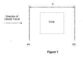
- Figure 1 shows a typical layout of piezoelectric sensors P1, P2 on the road, the piezoelectric sensors P1, P2 separated by a distance d.
- the piezoelectric sensors P1, P2 are typically positioned such that they are parallel to one another and perpendicular to the direction of vehicle travel.
- the piezoelectric sensors P1, P2 may be embedded in the road surface.
- the system includes an inductive loop positioned between the two piezoelectric sensors P1, P2 to sense the presence of the vehicle.
- the loop may also be embedded in the road surface.
- the inductive loop assists the system in grouping together the signals received from the piezoelectric sensors for a single vehicle.
- an induction loop causes the speed determination system to be less susceptible to interference since the inductive loop itself is not susceptible to environmental factors such as vibrations, which may trigger false signals in the piezoelectric sensors.
- any noise signals which would ordinarily be received as output from the piezoelectric sensors, are disregarded.
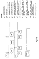
- Figure 2 is a simplified diagram representing the signals which would be emitted by a first and second piezoelectric sensor which are separated by a distance as triggered by a vehicle having a front and rear axle.
- the system is associated with a camera, which is used to record an image of the vehicle to enable the vehicle to be identified.
- the recorded images can be subsequently used to establish the type of vehicle for which a reading was recorded such that the vehicle can be classified according to type for verification of the readings as discussed below.
- the system may further include a database, which contains information relating to various vehicle types. This information may include a variety of specifications such as the make, model and year of the vehicle, a validated wheel base measurement, axle count, vehicle mass and the like. In one form of the invention, it is envisioned that the database could include a Vehicle Registration Database.
- measured vehicle data including wheelbase measurements and axle counts may be validated using a physical measurement taken at a time after the measurements or readings have been recorded for a particular vehicle. This is because elements of vehicle data such as wheelbase measurements and axle counts will remain constant over time. It is therefore envisaged that if a reading pertaining to a particular vehicle was disputed by the vehicle owner and/or driver at some time after the reading was determined by the system, it would be possible to validate the accuracy of that reading by comparing the wheelbase measurement and/or axle count determined by the system with an actual or physically measured wheelbase measurement and/or axle measurement. As an alternative to physically measuring the wheelbase measurement and/or axle count, such actual measurements may be obtained from a vehicle manufacturer.
- the invention enables readings determined by the system to be used to add records to the database in instances where data on a particular vehicle type is not available.
- vehicle speed is determined by determining the speed of the front axle independently from the speed of the rear axle. Determining the axle speeds independently in this manner makes it possible for the system to use the speed of the front axle to verify that the speed of the rear axle is correct. That is, if a distance, which is less than the wheel base of the vehicle, separates the first and second piezoelectric sensors from each other, the speed of the front axle would not be expected to vary considerably from the speed of the rear axle. Therefore, by performing checks to verify that the speed of the front axle and the speed of the rear axle vary only within a set tolerance of one another, a system operator will be alerted to any significant errors which may need to be addressed.
- the speed of the first axle may be determined by recording a first time interval ⁇ ts 1 between the front axle triggering a signal in the first piezoelectric sensor and the front axle triggering a signal in the second piezoelectric sensor.
- the speed of the rear axle is determined in a similar manner.
- a second time interval ⁇ ts 2 is recorded by measuring the time interval between the rear axle triggering a signal in the first piezoelectric sensor and the rear axle triggering a signal in the second piezoelectric sensor.
- the computed speeds s 1 and s 2 are then compared to ensure that the axle speed values for the front axle and the rear axle vary only within set tolerances of one another. It is noted that if s 1 is equal to s 2 , then cs 1 is equal to cs 2 . Any error in the speed determination will be a result of an error in the calibrated distance between the first and second piezoelectric sensors, or an error in the measured time interval.
- Determination of the wheel base of the vehicle whose speed is being determined provides for further verification of the determined speed. This may be achieved by measuring a third time interval ⁇ twb between the front axle triggering the second piezoelectric sensor and the rear axle triggering the first piezoelectric sensor.
- the third time interval is used in association with previously discussed variables (i.e. the first and second time intervals and the distance) to determine the wheel base of the vehicle.
- the wheel base of the vehicle is preferably determined twice, being once determined relative to the first piezoelectric sensor and being once determined relative to the second piezoelectric sensor.
- any errors in the wheel base determination will be a result of an error in the calibrated distance between the first and second piezoelectric sensors, or an error in the measured time interval.
- the determination of the first and second wheel base measurements is used to assist the identification of errors in the speed determined for the front axle and the speed determined for the rear axle. Since the wheel base determined by the method of the invention is dependent on the distance variable and not the distance in combination with another variable such as freq, as used in the axle speed computation, the wheel base determination is used to calibrate the system.
- the two wheel base determinations should be consistent. Clearly, if a first wheel base measurement is computed relative to the first piezoelectric sensor and the second wheel base measurement is computed relative to the second piezoelectric sensor, both computations would be expected to give an identical value for a correctly calibrated system, since the wheel base is not a variable feature of the vehicle.
- Variation in the crystal frequency freq can change the measured speed but not the wheel base measurement.
- the system can implement a separate device that injects piezo-like signals into the system. System detection is disabled at regular intervals and the separate system will generate signals that correspond to a known speed. If the system detects the speed correctly it means either that the crystal frequencies are still within specified tolerances or that both crystals have changed frequencies by the same amount. The second option is very unlikely especially if a different type of crystal is used.
- the system may further include means for counting the signals emitted by the first and second piezoelectric sensors by each vehicle. Counting the number of signals emitted provides an additional error check, since the number of signals emitted by the first piezoelectric sensor should be the same as the number of signals emitted by the second piezoelectric sensor if the system is free of significant errors. Any discrepancies in the number of signals emitted by the first piezoelectric sensor compared with those emitted by the second piezoelectric sensor indicate that noise signals were present during signal measurement. Therefore, the signal count can assist in the reduction of errors due to scatter and signal reflection.
- the system may be configured so that any readings which do not have identical signal counts for the first and second piezoelectric sensors are rejected by the system.
- the number of signals triggered in the first piezoelectric sensor and the second piezoelectric sensor for each vehicle may be used to determine a number of axles associated with the vehicle.
- the axle count obtained from the system can be subsequently verified by reference to the recorded image of the vehicle. If the number of axles the vehicle has is known, and the number of signals exceeds the number of signals anticipated for the number of axles on the vehicle, additional signals recorded must be signal errors.
- the system may be calibrated by taking a physical wheelbase measurement, obtaining actual wheelbase measurements from the vehicle manufacturer, or by referring to the database of vehicle types, makes and models with their associated wheel base lengths.
- the system operator elects to verify the measurements, the operator selects a vehicle and compares the wheel base measured by the system against the known wheel base for that vehicle type. If the measured values fail to match the known values, the operator identified that there is a problem with the calibration, in this example, clearly the distance between the first and second piezoelectric sensors is out of calibration.
- the system may be configured to verify the wheel base measurement and axle count each time that a speeding vehicle is detected. This enables the performance of the system to be continually monitored.
Abstract
Description
- The present invention relates generally to a system for determining the speed of a vehicle. More particularly, the invention relates to a system for determining the speed of a vehicle using sensors. The invention further provides a method for determining the speed of a vehicle and a method for calibrating the system.
- Piezoelectric materials convert mechanical stress or strain into signals of electrical energy. The flexibility, robustness and relatively low cost of piezoelectric materials make them particularly suitable for use in sensors.
- Piezoelectric sensor systems are used in the collection of traffic data. Such sensors may be temporarily or permanently installed on a road surface across one or more lanes of traffic. Piezoelectric sensors which are configured to collect traffic data may have application as vehicle counters, weight-in-motion sensors, vehicle classification systems, red-light cameras or speed detectors.
- In spite of their utility, piezoelectric sensors are prone to certain types of errors. Most sources of error in piezoelectric sensor systems can be broadly classified as vehicle, environment, system or roadway dependent.
- In order to achieve optimum performance of piezoelectric sensor systems, sensor installation is a critical factor and care must be taken in selecting a suitable site and installing the apparatus so as to minimise environmental and roadway dependent errors. The piezoelectric sensor system should be located on a straight, flat section of road to minimise speed variations. Similarly, sites approaching or leaving intersections or traffic lights should be avoided. Environment dependent errors may occur due to factors such as vibration, which may generate signals that distort the data collected.
- System dependent errors include problems such as scatter and signal reflections. The signal-to-noise ratio for piezoelectric systems is typically relatively poor.
- Sources of error dependent on factors such as vehicle dynamics and environmental factors are inherent in all piezoelectric systems and are difficult to compensate for. Therefore, system designers and manufacturers must determine ways in which the impact of system dependent errors such as signal errors can be reduced.
- The discussion of the background to the invention included herein is included to explain the context of the invention. This is not to be taken as an admission that any of the material referred to were published, known or part of the common general knowledge as at the priority date of the claims. However,
DE-19925962 andEP 1361488 disclose sensor-based speed verification systems. - According to an aspect of the present invention, there is provided a method for verifying the speed of a vehicle having at least a front axle and a rear axle using sensors, the sensors being separated by a distance, the method including the following steps:
- (a) sensing a presence of the vehicle;
- (b) recording an image of the vehicle;
- (c) triggering the sensors to emit a signal;
- (d) receiving the signals emitted by the sensors;
- (e) determining the speed of the vehicle based on the received signals; and
- (f) determining a wheel base measurement for the vehicle based on the received signals;
- (g) identifying a vehicle from the recorded image of the vehicle;
- (h) comparing the determined wheel base measurement to a validated wheel base measurement of the vehicle being sensed; and
- (i) identifying a discrepancy between the determined wheel base measurement and the validated wheel base measurement of the vehicle being sensed as potential errors in the speed of the vehicle determined by step (e).
- The method of the invention is suitable for speed verification in all vehicles having more than one axle. For vehicles having in excess of two axles, the speed of each additional axle is determined independently. The wheel base measurement consists of the length between the axles of the vehicle.
- The sensors may be any suitable type of sensor. Suitable types include optical sensors, magnetic sensors, piezoelectric sensors, fibre optic sensors and many other known types of sensors. The sensors may be permanently installed on a roadway,
- The speed of the vehicle may be determined by a method including the following steps:
- (a) measuring a first time interval between the front axle triggering a signal in the first sensor and the front axle triggering a signal in the second sensor;
- (b) measuring a second time interval between the rear axle triggering a signal in the first sensor and the rear axle triggering a signal in the second sensor;
- (c) computing the speed of the front axle relative to the distance separating the first and second sensors and the first time interval; and
- (d) computing the speed of the rear axle relative to the distance separating the first and second sensors and the second time interval.
- Preferably, two independent wheel base measurements are determined by a method including the following steps:
- (a) measuring a third time interval between the front axle triggering a signal in the second sensor and the rear axle triggering a signal in the first sensor;
- (b) computing a first wheel base measurement for the vehicle relative to the first and third time intervals and the distance; and
- (c) computing a second wheel base measurement for the vehicle relative to the second and third time intervals and the distance.
- More preferably, the method further includes the step of counting the signals triggered by the first and second sensors by each vehicle, wherein the number of signals triggered in each sensor is used to determine a number of axles associated with the vehicle and the number of the axles determined is compared to an actual number of axles in the vehicle being sensed such that any discrepancy between them is indicative of potential errors in the speed of the vehicle determined by the method.
- The method may further include the step of periodically calibrating the system by injecting into the system signals simulating sensor signals for a known vehicle speed and comparing the determined vehicle speed with the known vehicle speed.
- The method may further include the following step:
- (j) providing a database containing data relating to various vehicle types associated with vehicle specifications including a validated wheel base measurement for each vehicle type;
- According to a further aspect of the present invention, there is provided a system for verifying the speed of a vehicle having at least a front and rear axle, the system including;
- (a) a camera for recording an image of the vehicle to enable the vehicle to be identified;
- (b) at least two sensors separated by a distance which are triggered to emit a signal by the front and rear axles ;
- (c) means for receiving the signals emitted by the sensors;
- (d) means for using the signals to determine the speed of the vehicle; and
- (e) means for using the signals to determine a wheel base measurement for the vehicle;
- (f) means for identifying a vehicle from the recorded image of the vehicle;
- (g) means for comparing the wheel base measurement determined by the system to a validated wheel base measurement of the vehicle being sensed; and
- (h) means for identifying any discrepancy between the determined wheel base measurement and the validated wheel base measurement of the vehicle being sensed as an indication of potential errors in the speed of the vehicle determined by the system.
- The means for determining the speed of the vehicle may include:
- (a) means for determining a first time interval between the front axle triggering a signal in the first sensor and the front axle triggering a signal in the second sensor;
- (b) means for determining a second time interval between the rear axle triggering a signal in the first sensor and the rear axle triggering a signal in the second sensor;
- (c) means for computing the speed of the front axle relative to the distance separating the first and second sensors and the first time interval; and
- (d) means for computing the speed of the rear axle relative to the distance separating the first and second sensors and the second time interval.
- Preferably, two independent wheel base measurements are determined for each vehicle.
- More preferably, the means for determining the wheel base measurements for the vehicle include;
- (a) means for determining a third time interval between the front axle triggering a signal in the second sensor and the rear axle triggering a signal in the first sensor; and
- (b) means for computing a first wheel base measurement for the vehicle relative to the first and third time intervals and the distance; and
- (c) means for computing a second wheel base measurement for the vehicle relative to the second and third time intervals and the distance.
- Preferably, the system also includes means for counting the signals triggered by the first and second sensors by each vehicle, wherein the number of signals triggered in each sensor is used to determine a number of axles associated with the vehicle and the number of axles determined is compared to an actual number of axles in the vehicle being sensed such that any discrepancy between them is indicative of potential errors in the speed of the vehicle determined by the system.
- The system may further include means for injecting into the system signals simulating sensor signals for a known vehicle speed and comparing the determined vehicle speed with the known vehicle speed to calibrate the system.
- The system may include:
- (i) a database containing data relating to various vehicle types associated with vehicle specifications including a validated wheel base measurement for each vehicle type;
- The system may include:
- (j) means for using the signals to determine the number of axles for the vehicle; and
- (k) a database containing data relating to various vehicle types associated with vehicle specifications including a validated number of axles for each vehicle type;
- Preferably, the database includes an expert system whereby axle counts and/or wheelbase measurements for vehicle types are learned from measurements made by the system and then added to the database. More preferably, the axle count and Wheelbase measurements for a particular vehicle type are learned from deriving figures for a statistically significant number of examples of that particular vehicle type.
- The previously mentioned method may include the step of:
- (k) maintaining a register of speed and wheel base measurement data and discrepancies from validated wheel base measurement data;
- It is an advantage of the present invention that the speed of a vehicle can be determined with increased accuracy due to a number of integral error checks which serve to reduce the impact of noise generated signals which may be attributed to inherent system errors.
- The invention will now be described in further detail by reference to the attached drawings illustrating example forms of the invention. It is to be understood that the particularity of the drawings does not supersede the generality of the preceding description of the invention. In the drawings:
-
Figure 1 is a plan view of a typical layout of piezoelectric sensors on the road. -
Figure 2 is a simplified diagram of the signals typically emitted by two piezoelectric sensors separated by a distance as triggered by a vehicle having two axles according to an embodiment of the present invention. - In order to better describe the invention, it is to be detailed with respect to the measurement of the speed of a vehicle having two axles, being a front and a rear axle, and a wheel base which is longer than the distance between two piezoelectric sensors. However, it would be apparent to the person skilled in the art that the method of the invention and the system disclosed herein, has similar utility in determining the speed of a vehicle having in excess of two axles.
-
Figure 1 shows a typical layout of piezoelectric sensors P1, P2 on the road, the piezoelectric sensors P1, P2 separated by a distance d. The piezoelectric sensors P1, P2 are typically positioned such that they are parallel to one another and perpendicular to the direction of vehicle travel. The piezoelectric sensors P1, P2 may be embedded in the road surface. - The system includes an inductive loop positioned between the two piezoelectric sensors P1, P2 to sense the presence of the vehicle. The loop may also be embedded in the road surface. The inductive loop assists the system in grouping together the signals received from the piezoelectric sensors for a single vehicle. Furthermore, an induction loop causes the speed determination system to be less susceptible to interference since the inductive loop itself is not susceptible to environmental factors such as vibrations, which may trigger false signals in the piezoelectric sensors. When the inductive loop is not activated to indicate the presence of a vehicle, any noise signals, which would ordinarily be received as output from the piezoelectric sensors, are disregarded.
-
Figure 2 is a simplified diagram representing the signals which would be emitted by a first and second piezoelectric sensor which are separated by a distance as triggered by a vehicle having a front and rear axle. - The system is associated with a camera, which is used to record an image of the vehicle to enable the vehicle to be identified. The recorded images can be subsequently used to establish the type of vehicle for which a reading was recorded such that the vehicle can be classified according to type for verification of the readings as discussed below.
- The system may further include a database, which contains information relating to various vehicle types. This information may include a variety of specifications such as the make, model and year of the vehicle, a validated wheel base measurement, axle count, vehicle mass and the like. In one form of the invention, it is envisioned that the database could include a Vehicle Registration Database.
- As an alternative to storing information relating to the vehicle types in a database which is associated with the system, measured vehicle data including wheelbase measurements and axle counts may be validated using a physical measurement taken at a time after the measurements or readings have been recorded for a particular vehicle. This is because elements of vehicle data such as wheelbase measurements and axle counts will remain constant over time. It is therefore envisaged that if a reading pertaining to a particular vehicle was disputed by the vehicle owner and/or driver at some time after the reading was determined by the system, it would be possible to validate the accuracy of that reading by comparing the wheelbase measurement and/or axle count determined by the system with an actual or physically measured wheelbase measurement and/or axle measurement. As an alternative to physically measuring the wheelbase measurement and/or axle count, such actual measurements may be obtained from a vehicle manufacturer.
- Any discrepancies between the measured data and the anticipated readings (i.e. actual measurements or validated measurements stored in the database) indicate that there are potential errors in the system. Moreover, where the system employs a database, the invention enables readings determined by the system to be used to add records to the database in instances where data on a particular vehicle type is not available.
- According to the embodiment of the invention exemplified in
Figure 2 , vehicle speed is determined by determining the speed of the front axle independently from the speed of the rear axle. Determining the axle speeds independently in this manner makes it possible for the system to use the speed of the front axle to verify that the speed of the rear axle is correct. That is, if a distance, which is less than the wheel base of the vehicle, separates the first and second piezoelectric sensors from each other, the speed of the front axle would not be expected to vary considerably from the speed of the rear axle. Therefore, by performing checks to verify that the speed of the front axle and the speed of the rear axle vary only within a set tolerance of one another, a system operator will be alerted to any significant errors which may need to be addressed. - The speed of the first axle may be determined by recording a first time interval Δts1 between the front axle triggering a signal in the first piezoelectric sensor and the front axle triggering a signal in the second piezoelectric sensor. The time interval Δts1 is measured by reference to a crystal frequency, freq. Therefore, the time interval is computed by the following formula:

where cs1 is the number of interval counts or the count speed. - Once the first time interval has been determined, the speed s1 of the front axle is computed by the following formula:

where d is the distance separating the two piezoelectric sensors. - The speed of the rear axle is determined in a similar manner. A second time interval Δts2 is recorded by measuring the time interval between the rear axle triggering a signal in the first piezoelectric sensor and the rear axle triggering a signal in the second piezoelectric sensor. The speed s2 of the rear axle is then computed by the following formula:

- The computed speeds s1 and s2 are then compared to ensure that the axle speed values for the front axle and the rear axle vary only within set tolerances of one another. It is noted that if s1 is equal to s2, then cs1 is equal to cs2. Any error in the speed determination will be a result of an error in the calibrated distance between the first and second piezoelectric sensors, or an error in the measured time interval. The error can be computed according to the following formula:

- Measuring the speed of the front and rear axles independently enables the vehicle speed to be verified.
- Determination of the wheel base of the vehicle whose speed is being determined provides for further verification of the determined speed. This may be achieved by measuring a third time interval Δtwb between the front axle triggering the second piezoelectric sensor and the rear axle triggering the first piezoelectric sensor. The third time interval is used in association with previously discussed variables (i.e. the first and second time intervals and the distance) to determine the wheel base of the vehicle. The wheel base of the vehicle is preferably determined twice, being once determined relative to the first piezoelectric sensor and being once determined relative to the second piezoelectric sensor.
- The wheel base determined in relation to the first piezoelectric sensor is computed by the following formula:

where cwb is the number of interval counts corresponding to the time interval Δtwb. - The wheel base determined in relation to the second piezoelectric sensor is computed by the following formula:

- Any errors in the wheel base determination will be a result of an error in the calibrated distance between the first and second piezoelectric sensors, or an error in the measured time interval. The error can be computed according to the following formula:

- The determination of the first and second wheel base measurements is used to assist the identification of errors in the speed determined for the front axle and the speed determined for the rear axle. Since the wheel base determined by the method of the invention is dependent on the distance variable and not the distance in combination with another variable such as freq, as used in the axle speed computation, the wheel base determination is used to calibrate the system.
- The two wheel base determinations should be consistent. Clearly, if a first wheel base measurement is computed relative to the first piezoelectric sensor and the second wheel base measurement is computed relative to the second piezoelectric sensor, both computations would be expected to give an identical value for a correctly calibrated system, since the wheel base is not a variable feature of the vehicle.
- Variation in the crystal frequency freq can change the measured speed but not the wheel base measurement. To avoid this problem the system can implement a separate device that injects piezo-like signals into the system. System detection is disabled at regular intervals and the separate system will generate signals that correspond to a known speed. If the system detects the speed correctly it means either that the crystal frequencies are still within specified tolerances or that both crystals have changed frequencies by the same amount. The second option is very unlikely especially if a different type of crystal is used.
- The system may further include means for counting the signals emitted by the first and second piezoelectric sensors by each vehicle. Counting the number of signals emitted provides an additional error check, since the number of signals emitted by the first piezoelectric sensor should be the same as the number of signals emitted by the second piezoelectric sensor if the system is free of significant errors. Any discrepancies in the number of signals emitted by the first piezoelectric sensor compared with those emitted by the second piezoelectric sensor indicate that noise signals were present during signal measurement. Therefore, the signal count can assist in the reduction of errors due to scatter and signal reflection.
- The system may be configured so that any readings which do not have identical signal counts for the first and second piezoelectric sensors are rejected by the system.
- The number of signals triggered in the first piezoelectric sensor and the second piezoelectric sensor for each vehicle may be used to determine a number of axles associated with the vehicle. The axle count obtained from the system can be subsequently verified by reference to the recorded image of the vehicle. If the number of axles the vehicle has is known, and the number of signals exceeds the number of signals anticipated for the number of axles on the vehicle, additional signals recorded must be signal errors.
- The system may be calibrated by taking a physical wheelbase measurement, obtaining actual wheelbase measurements from the vehicle manufacturer, or by referring to the database of vehicle types, makes and models with their associated wheel base lengths. When the system operator elects to verify the measurements, the operator selects a vehicle and compares the wheel base measured by the system against the known wheel base for that vehicle type. If the measured values fail to match the known values, the operator identified that there is a problem with the calibration, in this example, clearly the distance between the first and second piezoelectric sensors is out of calibration.
- The system may be configured to verify the wheel base measurement and axle count each time that a speeding vehicle is detected. This enables the performance of the system to be continually monitored.
- Variations in the frequency may adversely affect speed determination by the system, however, such variations will have no impact on the wheel base determinations making these ideal for calibration of the distance between the piezoelectric sensors.
Claims (16)
- A method for verifying the speed of a vehicle having at least a front axle and a rear axle using sensors, the sensors being separated by a distance, the method including the following steps:(a) sensing a presence of the vehicle;(b) recording an image of the vehicle;(c) triggering the sensors to emit a signal;(d) receiving the signals emitted by the sensors;(e) determining the speed of the vehicle based on the received signals; and(f) determining a wheel base measurement for the vehicle based on the received signals;(g) identifying a vehicle from the recorded image of the vehicle;(h) comparing the determined wheel base measurement to a validated wheel base measurement of the vehicle being sensed; and(i) identifying a discrepancy between the determined wheel base measurement and the validated wheel base measurement of the vehicle being sensed as potential errors in the speed of the vehicle determined by step (e).
- A method according to claim 1, wherein the speed of the vehicle is determined by a method including the following steps:(a) measuring a first time interval between the front axle triggering a signal in the first sensor and the front axle triggering a signal in the second sensor;(b) measuring a second time interval between the rear axle triggering a signal in the first sensor and the rear axle triggering a signal in the second sensor;(c) computing the speed of the front axle relative to the distance separating the first and second sensors and the first time interval; and(d) computing the speed of the rear axle relative to the distance separating the first and second sensors and the second time interval.
- A method according to claim 2, wherein two independent wheel base measurements are determined by a method including the following steps:(a) measuring a third time interval between the front axle triggering a signal in the second sensor and the rear axle triggering a signal in the first sensor;(b) computing a first wheel base measurement for the vehicle relative to the first and third time intervals and the distance; and(c) computing a second wheel base measurement for the vehicle relative to the second and third time intervals and the distance.
- A method according to anyone of claims 1 to 3, further including the step of counting the signals triggered by the first and second sensors by each vehicle, wherein the number of signals triggered in each sensor is used to determine a number of axles associated with the vehicle and the number of the axles determined is compared to an actual number of axles in the vehicle being sensed such that any discrepancy between them is indicative of potential errors in the speed of the vehicle determined by the method.
- A method according to any one of claims 1 to 4, further including the step of periodically calibrating the system by injecting into the system signals simulating sensor signals for a known vehicle speed and comparing the determined vehicle speed with the known vehicle speed.
- A method according to claim 1, further comprising the following steps:(j) providing a database containing data relating to various vehicle types associated with vehicle specifications including a validated wheel base measurement for each vehicle type;wherein the wheel base measurement determined by the method is compared to the validated wheel base measurement stored in the database.
- A system for verifying the speed of a vehicle having at least a front and rear axle, the system including:(a) a camera for recording an image of the vehicle to enable the vehicle to be identified;(b) at least two sensors separated by a distance which are triggered to emit a signal by the front and rear axles;(c) means for receiving the signals emitted by the sensors;(d) means for using the signals to determine the speed of the vehicle; and(e) means for using the signals to determine a wheel base measurement for the vehicle;(f) means for identifying a vehicle from the recorded image of the vehicle;(g) means for comparing the wheel base measurement determined by the system to a validated wheel base measurement of the vehicle being sensed; and(h) means for identifying any discrepancy between the determined wheel base measurement and the validated wheel base measurement of the vehicle being sensed as an indication of potential errors in the speed of the vehicle determined by the system.
- A system according to claim 7, wherein the means for determining the speed of the vehicle includes:(a) means for determining a first time interval between the front axle triggering a signal in the first sensor and the front axle triggering a signal in the second sensor;(b) means for determining a second time interval between the rear axle triggering a signal in the first sensor and the rear axle triggering a signal in the second sensor;(c) means for computing the speed of the front axle relative to the distance separating the first and second sensors and the first time interval; and(d) means for computing the speed of the rear axle relative to the distance separating the first and second sensors and the second time interval.
- A system according to claim 7 or 8, wherein two independent wheel base measurements are determined for each vehicle.
- A system according to any one of claims 7 to 9, wherein the means for determining the wheel base measurements for the vehicle includes(a) means for determining a third time interval between the front axle triggering a signal in the second sensor and the rear axle triggering a signal in the first sensor; and(b) means for computing a first wheel base measurement for the vehicle relative to the first and third time intervals and the distance; and(c) means for computing a second wheel base measurement for the vehicle relative to the second and third time intervals and the distance.
- A system according to any one of claims 7 to 10, further including means for counting the signals triggered by the first and second sensors by each vehicle, wherein the number of signals triggered in each sensor is used to determine a number of axles associated with the vehicle and the number of axles determined is compared to an actual number of axles in the vehicle being sensed such that any discrepancy between them is indicative of potential errors in the speed of the vehicle determined by the system.
- A system according to any one of claims 7 to 11, further including means for injecting into the system signals simulating sensor signals for a known vehicle speed and comparing the determined vehicle speed with the known vehicle speed to calibrate the system.
- A system according to claim 7, further including:(i) a database containing data relating to various vehicle types associated with vehicle specifications including a validated wheel base measurement for each vehicle type;wherein the wheel base measurement determined by the system is compared to the validated wheel base measurement stored in the database.
- A system according to claim 7, further including:(j) means for using the signals to determine the number of axles for the vehicle; and(k) a database containing data relating to various vehicle types associated with vehicle specifications including a validated number of axles for each vehicle type wherein the axle count determined by the system is compared to the validated axle count stored in the database.
- A system according to claim 13 or 14 wherein the database includes an expert system whereby axle counts and/or wheelbase measurements for vehicle types are learned from measurements made by the system and then added to the database.
- The method according to claim 1, further comprising the steps of:(k) maintaining a register of speed and wheel base measurement data and discrepancies from validated wheel base measurement data;wherein analysis of any discrepancies between the determined wheel base measurement data and the validated wheel base measurement data is used to determine error trends and enable system calibration.
Priority Applications (1)
| Application Number | Priority Date | Filing Date | Title |
|---|---|---|---|
| PL04802116T PL1702313T3 (en) | 2003-12-24 | 2004-12-21 | Vehicle speed determination system and method |
Applications Claiming Priority (2)
| Application Number | Priority Date | Filing Date | Title |
|---|---|---|---|
| AU2003907181A AU2003907181A0 (en) | 2003-12-24 | Vehicle speed determination system and method | |
| PCT/AU2004/001815 WO2005062275A1 (en) | 2003-12-24 | 2004-12-21 | Vehicle speed determination system and method |
Publications (3)
| Publication Number | Publication Date |
|---|---|
| EP1702313A1 EP1702313A1 (en) | 2006-09-20 |
| EP1702313A4 EP1702313A4 (en) | 2009-11-11 |
| EP1702313B1 true EP1702313B1 (en) | 2010-12-01 |
Family
ID=34705569
Family Applications (1)
| Application Number | Title | Priority Date | Filing Date |
|---|---|---|---|
| EP04802116A Active EP1702313B1 (en) | 2003-12-24 | 2004-12-21 | Vehicle speed determination system and method |
Country Status (9)
| Country | Link |
|---|---|
| US (1) | US8489354B2 (en) |
| EP (1) | EP1702313B1 (en) |
| AT (1) | ATE490471T1 (en) |
| CA (1) | CA2550862A1 (en) |
| DE (1) | DE602004030375D1 (en) |
| ES (1) | ES2355319T3 (en) |
| PL (1) | PL1702313T3 (en) |
| WO (1) | WO2005062275A1 (en) |
| ZA (1) | ZA200605183B (en) |
Families Citing this family (11)
| Publication number | Priority date | Publication date | Assignee | Title |
|---|---|---|---|---|
| DE102006040297B4 (en) * | 2006-08-29 | 2010-12-09 | Continental Automotive Gmbh | Speed detection for a tachograph system |
| US20080231835A1 (en) * | 2007-03-23 | 2008-09-25 | Keigo Iizuka | Divergence ratio distance mapping camera |
| DE102008006840A1 (en) * | 2008-01-30 | 2009-08-13 | Continental Automotive Gmbh | Data transmission method and tachograph system |
| EP2535881B1 (en) | 2010-02-08 | 2015-10-28 | Obshchestvo s ogranichennoj otvetstvennost'ju "Korporazija "Stroy Invest Proekt M" | Method and device for determining the speed of travel and coordinates of vehicles and subsequently identifying same and automatically recording road traffic offences |
| NL2009948C2 (en) * | 2012-12-10 | 2014-06-11 | Stertil Bv | Wheel base measuring lifting system for lifting a vehicle and method therefor. |
| US9208681B2 (en) | 2014-03-27 | 2015-12-08 | Xerox Corporation | Vehicle wheel and axle sensing method and system |
| DK3096305T3 (en) * | 2015-05-21 | 2018-10-01 | Vitronic Dr Ing Stein Bildverarbeitungssysteme Gmbh | Vehicle speed detection method and self-plausibility test |
| US11635764B2 (en) * | 2019-02-22 | 2023-04-25 | Uatc, Llc. | Motion prediction for autonomous devices |
| US11961335B1 (en) * | 2020-06-26 | 2024-04-16 | Harris County Toll Road Authority | Dual mode electronic toll road system |
| US11351999B2 (en) * | 2020-09-16 | 2022-06-07 | Xuan Binh Luu | Traffic collision warning device |
| GB2599442A (en) * | 2020-10-04 | 2022-04-06 | Gerard Bailey Samuel | Measuring vehicle speed in video capture |
Family Cites Families (17)
| Publication number | Priority date | Publication date | Assignee | Title |
|---|---|---|---|---|
| US3825734A (en) * | 1973-03-14 | 1974-07-23 | Reliance Electric Co | Monitor for moving vehicles |
| US3872283A (en) * | 1973-07-13 | 1975-03-18 | Cadre Corp | Vehicle identification method and apparatus |
| FR2254078B1 (en) * | 1973-12-07 | 1976-10-08 | Automatisme Cie Gle | |
| US5020236A (en) * | 1990-02-12 | 1991-06-04 | Pietzsch Ag | Method of measuring the distance between the axles or wheels of a vehicle, and device for doing so |
| US5455768A (en) * | 1992-11-06 | 1995-10-03 | Safetran Traffic Systems, Inc. | System for determining vehicle speed and presence |
| US5416711A (en) * | 1993-10-18 | 1995-05-16 | Grumman Aerospace Corporation | Infra-red sensor system for intelligent vehicle highway systems |
| CA2134717C (en) * | 1994-10-31 | 1999-02-23 | Rod Klashinsky | Traffic monitoring system with safe speed computations |
| US6075466A (en) * | 1996-07-19 | 2000-06-13 | Tracon Systems Ltd. | Passive road sensor for automatic monitoring and method thereof |
| DE19925962C1 (en) * | 1999-05-31 | 2001-03-22 | Siemens Ag | Speed measuring system calibration |
| DE19946226C1 (en) * | 1999-09-22 | 2001-03-29 | Siemens Ag | Method for determining vehicle wheels that have passed a point of delivery |
| US6750787B2 (en) * | 2000-03-17 | 2004-06-15 | Herbert A. Hutchinson | Optronic system for the measurement of vehicle traffic |
| US6828920B2 (en) * | 2001-06-04 | 2004-12-07 | Lockheed Martin Orincon Corporation | System and method for classifying vehicles |
| FR2830966B1 (en) * | 2001-10-11 | 2005-04-01 | Electronique Controle Mesure | PROCESS FOR PROCESSING SIGNALS PROVIDED BY PIEZOELECTRIC SENSORS IMPLANT IN A PAVEMENT FOR MEASURING SPEED OF VEHICLES |
| JP2003187376A (en) * | 2001-12-14 | 2003-07-04 | Mitsubishi Heavy Ind Ltd | Device and method for discriminating type of vehicle |
| US6876949B2 (en) * | 2002-03-08 | 2005-04-05 | Inductive Signature Technologies, Inc. | Normalization of inductive vehicle detector outputs |
| ATE367601T1 (en) * | 2002-05-07 | 2007-08-15 | Ages Arbeitsgemeinschaft Gebue | METHOD AND DEVICE FOR AUTOMATICALLY CLASSIFYING WHEELED VEHICLES |
| AU2003246652A1 (en) * | 2003-07-07 | 2005-01-28 | Nira Dynamics Ab | Method and system of determining the absolute velocity of a vehicle |
-
2004
- 2004-12-21 DE DE602004030375T patent/DE602004030375D1/en active Active
- 2004-12-21 PL PL04802116T patent/PL1702313T3/en unknown
- 2004-12-21 EP EP04802116A patent/EP1702313B1/en active Active
- 2004-12-21 US US10/584,703 patent/US8489354B2/en not_active Expired - Fee Related
- 2004-12-21 WO PCT/AU2004/001815 patent/WO2005062275A1/en active Application Filing
- 2004-12-21 ES ES04802116T patent/ES2355319T3/en active Active
- 2004-12-21 AT AT04802116T patent/ATE490471T1/en not_active IP Right Cessation
- 2004-12-21 CA CA002550862A patent/CA2550862A1/en not_active Abandoned
-
2006
- 2006-06-23 ZA ZA200605183A patent/ZA200605183B/en unknown
Also Published As
| Publication number | Publication date |
|---|---|
| ZA200605183B (en) | 2008-03-26 |
| ES2355319T3 (en) | 2011-03-24 |
| US8489354B2 (en) | 2013-07-16 |
| CA2550862A1 (en) | 2005-07-07 |
| PL1702313T3 (en) | 2011-05-31 |
| ATE490471T1 (en) | 2010-12-15 |
| WO2005062275A1 (en) | 2005-07-07 |
| US20110119013A1 (en) | 2011-05-19 |
| EP1702313A1 (en) | 2006-09-20 |
| EP1702313A4 (en) | 2009-11-11 |
| DE602004030375D1 (en) | 2011-01-13 |
Similar Documents
| Publication | Publication Date | Title |
|---|---|---|
| ZA200605183B (en) | Vehicle speed determination system and method | |
| CN101512347B (en) | Speed detection for a tachograph system | |
| JPH05225490A (en) | Vehicle type discriminating device | |
| CN107407693A (en) | System for estimating tire speed | |
| US10850588B2 (en) | Automated passenger counter systems and methods | |
| US4813004A (en) | Method for measuring the maximum gross weight of a motor vehicle | |
| JPH09512118A (en) | Magnetometer vehicle detector | |
| US5121097A (en) | System for preventing fraud in the use of a taximeter | |
| JP7424945B2 (en) | Failure detection device, toll collection system, failure detection method, and program | |
| AU2004303899B2 (en) | Vehicle speed determination system and method | |
| JPH07225891A (en) | Pedal for vehicle type deciding device | |
| JP2001283375A (en) | Vehicle sort measuring device | |
| JP3999347B2 (en) | Traffic volume measuring apparatus and method | |
| CN111060186A (en) | Axle weight weighing and axle type identification method for narrow strip type weighing system | |
| KR100811555B1 (en) | Apparatus for classfying a vehicle-type using vehicle side shape and method therefor | |
| JPS60108717A (en) | Vehicle-weight measuring apparatus | |
| JPH08235486A (en) | Automatic traffic density measuring system | |
| CN111108536B (en) | Apparatus and method for evaluating vehicles between straddle lanes | |
| JP3602226B2 (en) | Method and apparatus for measuring the number of passing vehicles | |
| JPS5827557B2 (en) | Vehicle type identification device | |
| JP7360492B2 (en) | How to check the measurement accuracy of an axle load meter | |
| CN111260809B (en) | Distance measuring and calculating method and system for vehicle-mounted unit and vehicle-mounted unit | |
| KR101017680B1 (en) | Apparatus for gathering vehicle information of wheel | |
| JP6845684B2 (en) | Vehicle length measuring device and vehicle length measuring method | |
| JP3049974B2 (en) | Traffic volume measuring device and traffic volume measuring method |
Legal Events
| Date | Code | Title | Description |
|---|---|---|---|
| PUAI | Public reference made under article 153(3) epc to a published international application that has entered the european phase |
Free format text: ORIGINAL CODE: 0009012 |
|
| 17P | Request for examination filed |
Effective date: 20060720 |
|
| AK | Designated contracting states |
Kind code of ref document: A1 Designated state(s): AT BE BG CH CY CZ DE DK EE ES FI FR GB GR HU IE IS IT LI LT LU MC NL PL PT RO SE SI SK TR |
|
| DAX | Request for extension of the european patent (deleted) | ||
| REG | Reference to a national code |
Ref country code: HK Ref legal event code: DE Ref document number: 1097077 Country of ref document: HK |
|
| RIC1 | Information provided on ipc code assigned before grant |
Ipc: G08G 1/052 20060101ALN20090831BHEP Ipc: G01P 3/66 20060101AFI20090831BHEP |
|
| A4 | Supplementary search report drawn up and despatched |
Effective date: 20090904 |
|
| 17Q | First examination report despatched |
Effective date: 20091202 |
|
| GRAP | Despatch of communication of intention to grant a patent |
Free format text: ORIGINAL CODE: EPIDOSNIGR1 |
|
| GRAS | Grant fee paid |
Free format text: ORIGINAL CODE: EPIDOSNIGR3 |
|
| GRAA | (expected) grant |
Free format text: ORIGINAL CODE: 0009210 |
|
| AK | Designated contracting states |
Kind code of ref document: B1 Designated state(s): AT BE BG CH CY CZ DE DK EE ES FI FR GB GR HU IE IS IT LI LT LU MC NL PL PT RO SE SI SK TR |
|
| REG | Reference to a national code |
Ref country code: GB Ref legal event code: FG4D |
|
| REG | Reference to a national code |
Ref country code: CH Ref legal event code: EP |
|
| REG | Reference to a national code |
Ref country code: IE Ref legal event code: FG4D |
|
| REF | Corresponds to: |
Ref document number: 602004030375 Country of ref document: DE Date of ref document: 20110113 Kind code of ref document: P |
|
| REG | Reference to a national code |
Ref country code: RO Ref legal event code: EPE |
|
| REG | Reference to a national code |
Ref country code: NL Ref legal event code: T3 |
|
| REG | Reference to a national code |
Ref country code: NL Ref legal event code: T3 |
|
| REG | Reference to a national code |
Ref country code: ES Ref legal event code: FG2A Ref document number: 2355319 Country of ref document: ES Kind code of ref document: T3 Effective date: 20110324 |
|
| PG25 | Lapsed in a contracting state [announced via postgrant information from national office to epo] |
Ref country code: LT Free format text: LAPSE BECAUSE OF FAILURE TO SUBMIT A TRANSLATION OF THE DESCRIPTION OR TO PAY THE FEE WITHIN THE PRESCRIBED TIME-LIMIT Effective date: 20101201 |
|
| LTIE | Lt: invalidation of european patent or patent extension |
Effective date: 20101201 |
|
| REG | Reference to a national code |
Ref country code: HU Ref legal event code: AG4A Ref document number: E010172 Country of ref document: HU |
|
| PG25 | Lapsed in a contracting state [announced via postgrant information from national office to epo] |
Ref country code: CY Free format text: LAPSE BECAUSE OF FAILURE TO SUBMIT A TRANSLATION OF THE DESCRIPTION OR TO PAY THE FEE WITHIN THE PRESCRIBED TIME-LIMIT Effective date: 20101201 Ref country code: SI Free format text: LAPSE BECAUSE OF FAILURE TO SUBMIT A TRANSLATION OF THE DESCRIPTION OR TO PAY THE FEE WITHIN THE PRESCRIBED TIME-LIMIT Effective date: 20101201 Ref country code: BG Free format text: LAPSE BECAUSE OF FAILURE TO SUBMIT A TRANSLATION OF THE DESCRIPTION OR TO PAY THE FEE WITHIN THE PRESCRIBED TIME-LIMIT Effective date: 20110301 Ref country code: SE Free format text: LAPSE BECAUSE OF FAILURE TO SUBMIT A TRANSLATION OF THE DESCRIPTION OR TO PAY THE FEE WITHIN THE PRESCRIBED TIME-LIMIT Effective date: 20101201 Ref country code: AT Free format text: LAPSE BECAUSE OF FAILURE TO SUBMIT A TRANSLATION OF THE DESCRIPTION OR TO PAY THE FEE WITHIN THE PRESCRIBED TIME-LIMIT Effective date: 20101201 Ref country code: FI Free format text: LAPSE BECAUSE OF FAILURE TO SUBMIT A TRANSLATION OF THE DESCRIPTION OR TO PAY THE FEE WITHIN THE PRESCRIBED TIME-LIMIT Effective date: 20101201 |
|
| PGFP | Annual fee paid to national office [announced via postgrant information from national office to epo] |
Ref country code: RO Payment date: 20101220 Year of fee payment: 7 |
|
| REG | Reference to a national code |
Ref country code: PL Ref legal event code: T3 |
|
| PG25 | Lapsed in a contracting state [announced via postgrant information from national office to epo] |
Ref country code: GR Free format text: LAPSE BECAUSE OF FAILURE TO SUBMIT A TRANSLATION OF THE DESCRIPTION OR TO PAY THE FEE WITHIN THE PRESCRIBED TIME-LIMIT Effective date: 20110302 |
|
| PG25 | Lapsed in a contracting state [announced via postgrant information from national office to epo] |
Ref country code: IS Free format text: LAPSE BECAUSE OF FAILURE TO SUBMIT A TRANSLATION OF THE DESCRIPTION OR TO PAY THE FEE WITHIN THE PRESCRIBED TIME-LIMIT Effective date: 20110401 Ref country code: PT Free format text: LAPSE BECAUSE OF FAILURE TO SUBMIT A TRANSLATION OF THE DESCRIPTION OR TO PAY THE FEE WITHIN THE PRESCRIBED TIME-LIMIT Effective date: 20110401 Ref country code: EE Free format text: LAPSE BECAUSE OF FAILURE TO SUBMIT A TRANSLATION OF THE DESCRIPTION OR TO PAY THE FEE WITHIN THE PRESCRIBED TIME-LIMIT Effective date: 20101201 Ref country code: MC Free format text: LAPSE BECAUSE OF NON-PAYMENT OF DUE FEES Effective date: 20101231 Ref country code: CZ Free format text: LAPSE BECAUSE OF FAILURE TO SUBMIT A TRANSLATION OF THE DESCRIPTION OR TO PAY THE FEE WITHIN THE PRESCRIBED TIME-LIMIT Effective date: 20101201 |
|
| REG | Reference to a national code |
Ref country code: CH Ref legal event code: PL |
|
| PG25 | Lapsed in a contracting state [announced via postgrant information from national office to epo] |
Ref country code: SK Free format text: LAPSE BECAUSE OF FAILURE TO SUBMIT A TRANSLATION OF THE DESCRIPTION OR TO PAY THE FEE WITHIN THE PRESCRIBED TIME-LIMIT Effective date: 20101201 |
|
| PGFP | Annual fee paid to national office [announced via postgrant information from national office to epo] |
Ref country code: PL Payment date: 20101215 Year of fee payment: 7 |
|
| PLBE | No opposition filed within time limit |
Free format text: ORIGINAL CODE: 0009261 |
|
| STAA | Information on the status of an ep patent application or granted ep patent |
Free format text: STATUS: NO OPPOSITION FILED WITHIN TIME LIMIT |
|
| PG25 | Lapsed in a contracting state [announced via postgrant information from national office to epo] |
Ref country code: CH Free format text: LAPSE BECAUSE OF NON-PAYMENT OF DUE FEES Effective date: 20101231 Ref country code: DK Free format text: LAPSE BECAUSE OF FAILURE TO SUBMIT A TRANSLATION OF THE DESCRIPTION OR TO PAY THE FEE WITHIN THE PRESCRIBED TIME-LIMIT Effective date: 20101201 Ref country code: LI Free format text: LAPSE BECAUSE OF NON-PAYMENT OF DUE FEES Effective date: 20101231 |
|
| 26N | No opposition filed |
Effective date: 20110902 |
|
| REG | Reference to a national code |
Ref country code: DE Ref legal event code: R097 Ref document number: 602004030375 Country of ref document: DE Effective date: 20110902 |
|
| PG25 | Lapsed in a contracting state [announced via postgrant information from national office to epo] |
Ref country code: IT Free format text: LAPSE BECAUSE OF FAILURE TO SUBMIT A TRANSLATION OF THE DESCRIPTION OR TO PAY THE FEE WITHIN THE PRESCRIBED TIME-LIMIT Effective date: 20101201 |
|
| PGFP | Annual fee paid to national office [announced via postgrant information from national office to epo] |
Ref country code: NL Payment date: 20111230 Year of fee payment: 8 Ref country code: HU Payment date: 20111228 Year of fee payment: 8 |
|
| PGFP | Annual fee paid to national office [announced via postgrant information from national office to epo] |
Ref country code: BE Payment date: 20111229 Year of fee payment: 8 |
|
| PGFP | Annual fee paid to national office [announced via postgrant information from national office to epo] |
Ref country code: FR Payment date: 20120201 Year of fee payment: 8 |
|
| PGFP | Annual fee paid to national office [announced via postgrant information from national office to epo] |
Ref country code: DE Payment date: 20111221 Year of fee payment: 8 |
|
| PG25 | Lapsed in a contracting state [announced via postgrant information from national office to epo] |
Ref country code: LU Free format text: LAPSE BECAUSE OF NON-PAYMENT OF DUE FEES Effective date: 20101221 |
|
| PG25 | Lapsed in a contracting state [announced via postgrant information from national office to epo] |
Ref country code: TR Free format text: LAPSE BECAUSE OF FAILURE TO SUBMIT A TRANSLATION OF THE DESCRIPTION OR TO PAY THE FEE WITHIN THE PRESCRIBED TIME-LIMIT Effective date: 20101201 |
|
| PGFP | Annual fee paid to national office [announced via postgrant information from national office to epo] |
Ref country code: ES Payment date: 20120104 Year of fee payment: 8 |
|
| BERE | Be: lapsed |
Owner name: REDFLEX TRAFFIC SYSTEMS PTY LTD. Effective date: 20121231 |
|
| REG | Reference to a national code |
Ref country code: NL Ref legal event code: V1 Effective date: 20130701 |
|
| REG | Reference to a national code |
Ref country code: HK Ref legal event code: WD Ref document number: 1097077 Country of ref document: HK |
|
| REG | Reference to a national code |
Ref country code: IE Ref legal event code: MM4A |
|
| REG | Reference to a national code |
Ref country code: FR Ref legal event code: ST Effective date: 20130830 |
|
| PG25 | Lapsed in a contracting state [announced via postgrant information from national office to epo] |
Ref country code: BE Free format text: LAPSE BECAUSE OF NON-PAYMENT OF DUE FEES Effective date: 20121231 |
|
| REG | Reference to a national code |
Ref country code: DE Ref legal event code: R119 Ref document number: 602004030375 Country of ref document: DE Effective date: 20130702 |
|
| PG25 | Lapsed in a contracting state [announced via postgrant information from national office to epo] |
Ref country code: IE Free format text: LAPSE BECAUSE OF NON-PAYMENT OF DUE FEES Effective date: 20121221 Ref country code: NL Free format text: LAPSE BECAUSE OF NON-PAYMENT OF DUE FEES Effective date: 20130701 Ref country code: DE Free format text: LAPSE BECAUSE OF NON-PAYMENT OF DUE FEES Effective date: 20130702 Ref country code: RO Free format text: LAPSE BECAUSE OF NON-PAYMENT OF DUE FEES Effective date: 20121221 |
|
| PG25 | Lapsed in a contracting state [announced via postgrant information from national office to epo] |
Ref country code: FR Free format text: LAPSE BECAUSE OF NON-PAYMENT OF DUE FEES Effective date: 20130102 |
|
| PGFP | Annual fee paid to national office [announced via postgrant information from national office to epo] |
Ref country code: IE Payment date: 20111201 Year of fee payment: 8 |
|
| PG25 | Lapsed in a contracting state [announced via postgrant information from national office to epo] |
Ref country code: PL Free format text: LAPSE BECAUSE OF NON-PAYMENT OF DUE FEES Effective date: 20121221 |
|
| REG | Reference to a national code |
Ref country code: ES Ref legal event code: FD2A Effective date: 20140307 |
|
| PG25 | Lapsed in a contracting state [announced via postgrant information from national office to epo] |
Ref country code: HU Free format text: LAPSE BECAUSE OF NON-PAYMENT OF DUE FEES Effective date: 20121222 |
|
| PG25 | Lapsed in a contracting state [announced via postgrant information from national office to epo] |
Ref country code: ES Free format text: LAPSE BECAUSE OF NON-PAYMENT OF DUE FEES Effective date: 20121222 |
|
| PGFP | Annual fee paid to national office [announced via postgrant information from national office to epo] |
Ref country code: GB Payment date: 20231102 Year of fee payment: 20 |