EP1702154B1 - Filtergeh use und herstellverfahren f r filtergeh use - Google Patents
Filtergeh use und herstellverfahren f r filtergeh use Download PDFInfo
- Publication number
- EP1702154B1 EP1702154B1 EP04804936A EP04804936A EP1702154B1 EP 1702154 B1 EP1702154 B1 EP 1702154B1 EP 04804936 A EP04804936 A EP 04804936A EP 04804936 A EP04804936 A EP 04804936A EP 1702154 B1 EP1702154 B1 EP 1702154B1
- Authority
- EP
- European Patent Office
- Prior art keywords
- housing
- filter
- housing part
- component
- mold cavity
- Prior art date
- Legal status (The legal status is an assumption and is not a legal conclusion. Google has not performed a legal analysis and makes no representation as to the accuracy of the status listed.)
- Not-in-force
Links
Images

Classifications
-
- B—PERFORMING OPERATIONS; TRANSPORTING
- B29—WORKING OF PLASTICS; WORKING OF SUBSTANCES IN A PLASTIC STATE IN GENERAL
- B29C—SHAPING OR JOINING OF PLASTICS; SHAPING OF MATERIAL IN A PLASTIC STATE, NOT OTHERWISE PROVIDED FOR; AFTER-TREATMENT OF THE SHAPED PRODUCTS, e.g. REPAIRING
- B29C41/00—Shaping by coating a mould, core or other substrate, i.e. by depositing material and stripping-off the shaped article; Apparatus therefor
- B29C41/02—Shaping by coating a mould, core or other substrate, i.e. by depositing material and stripping-off the shaped article; Apparatus therefor for making articles of definite length, i.e. discrete articles
- B29C41/04—Rotational or centrifugal casting, i.e. coating the inside of a mould by rotating the mould
- B29C41/06—Rotational or centrifugal casting, i.e. coating the inside of a mould by rotating the mould about two or more axes
-
- B—PERFORMING OPERATIONS; TRANSPORTING
- B01—PHYSICAL OR CHEMICAL PROCESSES OR APPARATUS IN GENERAL
- B01D—SEPARATION
- B01D46/00—Filters or filtering processes specially modified for separating dispersed particles from gases or vapours
- B01D46/0001—Making filtering elements
-
- B—PERFORMING OPERATIONS; TRANSPORTING
- B01—PHYSICAL OR CHEMICAL PROCESSES OR APPARATUS IN GENERAL
- B01D—SEPARATION
- B01D46/00—Filters or filtering processes specially modified for separating dispersed particles from gases or vapours
- B01D46/0002—Casings; Housings; Frame constructions
-
- B—PERFORMING OPERATIONS; TRANSPORTING
- B29—WORKING OF PLASTICS; WORKING OF SUBSTANCES IN A PLASTIC STATE IN GENERAL
- B29C—SHAPING OR JOINING OF PLASTICS; SHAPING OF MATERIAL IN A PLASTIC STATE, NOT OTHERWISE PROVIDED FOR; AFTER-TREATMENT OF THE SHAPED PRODUCTS, e.g. REPAIRING
- B29C65/00—Joining or sealing of preformed parts, e.g. welding of plastics materials; Apparatus therefor
- B29C65/56—Joining or sealing of preformed parts, e.g. welding of plastics materials; Apparatus therefor using mechanical means or mechanical connections, e.g. form-fits
- B29C65/562—Joining or sealing of preformed parts, e.g. welding of plastics materials; Apparatus therefor using mechanical means or mechanical connections, e.g. form-fits using extra joining elements, i.e. which are not integral with the parts to be joined
-
- B—PERFORMING OPERATIONS; TRANSPORTING
- B29—WORKING OF PLASTICS; WORKING OF SUBSTANCES IN A PLASTIC STATE IN GENERAL
- B29C—SHAPING OR JOINING OF PLASTICS; SHAPING OF MATERIAL IN A PLASTIC STATE, NOT OTHERWISE PROVIDED FOR; AFTER-TREATMENT OF THE SHAPED PRODUCTS, e.g. REPAIRING
- B29C65/00—Joining or sealing of preformed parts, e.g. welding of plastics materials; Apparatus therefor
- B29C65/56—Joining or sealing of preformed parts, e.g. welding of plastics materials; Apparatus therefor using mechanical means or mechanical connections, e.g. form-fits
- B29C65/58—Snap connection
-
- B—PERFORMING OPERATIONS; TRANSPORTING
- B29—WORKING OF PLASTICS; WORKING OF SUBSTANCES IN A PLASTIC STATE IN GENERAL
- B29C—SHAPING OR JOINING OF PLASTICS; SHAPING OF MATERIAL IN A PLASTIC STATE, NOT OTHERWISE PROVIDED FOR; AFTER-TREATMENT OF THE SHAPED PRODUCTS, e.g. REPAIRING
- B29C66/00—General aspects of processes or apparatus for joining preformed parts
- B29C66/50—General aspects of joining tubular articles; General aspects of joining long products, i.e. bars or profiled elements; General aspects of joining single elements to tubular articles, hollow articles or bars; General aspects of joining several hollow-preforms to form hollow or tubular articles
- B29C66/51—Joining tubular articles, profiled elements or bars; Joining single elements to tubular articles, hollow articles or bars; Joining several hollow-preforms to form hollow or tubular articles
- B29C66/54—Joining several hollow-preforms, e.g. half-shells, to form hollow articles, e.g. for making balls, containers; Joining several hollow-preforms, e.g. half-cylinders, to form tubular articles
- B29C66/542—Joining several hollow-preforms, e.g. half-shells, to form hollow articles, e.g. for making balls, containers; Joining several hollow-preforms, e.g. half-cylinders, to form tubular articles joining hollow covers or hollow bottoms to open ends of container bodies
-
- F—MECHANICAL ENGINEERING; LIGHTING; HEATING; WEAPONS; BLASTING
- F02—COMBUSTION ENGINES; HOT-GAS OR COMBUSTION-PRODUCT ENGINE PLANTS
- F02M—SUPPLYING COMBUSTION ENGINES IN GENERAL WITH COMBUSTIBLE MIXTURES OR CONSTITUENTS THEREOF
- F02M35/00—Combustion-air cleaners, air intakes, intake silencers, or induction systems specially adapted for, or arranged on, internal-combustion engines
- F02M35/02—Air cleaners
-
- B—PERFORMING OPERATIONS; TRANSPORTING
- B29—WORKING OF PLASTICS; WORKING OF SUBSTANCES IN A PLASTIC STATE IN GENERAL
- B29C—SHAPING OR JOINING OF PLASTICS; SHAPING OF MATERIAL IN A PLASTIC STATE, NOT OTHERWISE PROVIDED FOR; AFTER-TREATMENT OF THE SHAPED PRODUCTS, e.g. REPAIRING
- B29C2793/00—Shaping techniques involving a cutting or machining operation
- B29C2793/009—Shaping techniques involving a cutting or machining operation after shaping
-
- B—PERFORMING OPERATIONS; TRANSPORTING
- B29—WORKING OF PLASTICS; WORKING OF SUBSTANCES IN A PLASTIC STATE IN GENERAL
- B29C—SHAPING OR JOINING OF PLASTICS; SHAPING OF MATERIAL IN A PLASTIC STATE, NOT OTHERWISE PROVIDED FOR; AFTER-TREATMENT OF THE SHAPED PRODUCTS, e.g. REPAIRING
- B29C48/00—Extrusion moulding, i.e. expressing the moulding material through a die or nozzle which imparts the desired form; Apparatus therefor
- B29C48/001—Combinations of extrusion moulding with other shaping operations
-
- B—PERFORMING OPERATIONS; TRANSPORTING
- B29—WORKING OF PLASTICS; WORKING OF SUBSTANCES IN A PLASTIC STATE IN GENERAL
- B29C—SHAPING OR JOINING OF PLASTICS; SHAPING OF MATERIAL IN A PLASTIC STATE, NOT OTHERWISE PROVIDED FOR; AFTER-TREATMENT OF THE SHAPED PRODUCTS, e.g. REPAIRING
- B29C48/00—Extrusion moulding, i.e. expressing the moulding material through a die or nozzle which imparts the desired form; Apparatus therefor
- B29C48/03—Extrusion moulding, i.e. expressing the moulding material through a die or nozzle which imparts the desired form; Apparatus therefor characterised by the shape of the extruded material at extrusion
-
- B—PERFORMING OPERATIONS; TRANSPORTING
- B29—WORKING OF PLASTICS; WORKING OF SUBSTANCES IN A PLASTIC STATE IN GENERAL
- B29C—SHAPING OR JOINING OF PLASTICS; SHAPING OF MATERIAL IN A PLASTIC STATE, NOT OTHERWISE PROVIDED FOR; AFTER-TREATMENT OF THE SHAPED PRODUCTS, e.g. REPAIRING
- B29C66/00—General aspects of processes or apparatus for joining preformed parts
- B29C66/70—General aspects of processes or apparatus for joining preformed parts characterised by the composition, physical properties or the structure of the material of the parts to be joined; Joining with non-plastics material
- B29C66/71—General aspects of processes or apparatus for joining preformed parts characterised by the composition, physical properties or the structure of the material of the parts to be joined; Joining with non-plastics material characterised by the composition of the plastics material of the parts to be joined
-
- B—PERFORMING OPERATIONS; TRANSPORTING
- B29—WORKING OF PLASTICS; WORKING OF SUBSTANCES IN A PLASTIC STATE IN GENERAL
- B29C—SHAPING OR JOINING OF PLASTICS; SHAPING OF MATERIAL IN A PLASTIC STATE, NOT OTHERWISE PROVIDED FOR; AFTER-TREATMENT OF THE SHAPED PRODUCTS, e.g. REPAIRING
- B29C69/00—Combinations of shaping techniques not provided for in a single one of main groups B29C39/00 - B29C67/00, e.g. associations of moulding and joining techniques; Apparatus therefore
- B29C69/001—Combinations of shaping techniques not provided for in a single one of main groups B29C39/00 - B29C67/00, e.g. associations of moulding and joining techniques; Apparatus therefore a shaping technique combined with cutting, e.g. in parts or slices combined with rearranging and joining the cut parts
-
- B—PERFORMING OPERATIONS; TRANSPORTING
- B29—WORKING OF PLASTICS; WORKING OF SUBSTANCES IN A PLASTIC STATE IN GENERAL
- B29K—INDEXING SCHEME ASSOCIATED WITH SUBCLASSES B29B, B29C OR B29D, RELATING TO MOULDING MATERIALS OR TO MATERIALS FOR MOULDS, REINFORCEMENTS, FILLERS OR PREFORMED PARTS, e.g. INSERTS
- B29K2023/00—Use of polyalkenes or derivatives thereof as moulding material
-
- B—PERFORMING OPERATIONS; TRANSPORTING
- B29—WORKING OF PLASTICS; WORKING OF SUBSTANCES IN A PLASTIC STATE IN GENERAL
- B29K—INDEXING SCHEME ASSOCIATED WITH SUBCLASSES B29B, B29C OR B29D, RELATING TO MOULDING MATERIALS OR TO MATERIALS FOR MOULDS, REINFORCEMENTS, FILLERS OR PREFORMED PARTS, e.g. INSERTS
- B29K2105/00—Condition, form or state of moulded material or of the material to be shaped
- B29K2105/25—Solid
- B29K2105/251—Particles, powder or granules
-
- B—PERFORMING OPERATIONS; TRANSPORTING
- B29—WORKING OF PLASTICS; WORKING OF SUBSTANCES IN A PLASTIC STATE IN GENERAL
- B29L—INDEXING SCHEME ASSOCIATED WITH SUBCLASS B29C, RELATING TO PARTICULAR ARTICLES
- B29L2024/00—Articles with hollow walls
-
- B—PERFORMING OPERATIONS; TRANSPORTING
- B29—WORKING OF PLASTICS; WORKING OF SUBSTANCES IN A PLASTIC STATE IN GENERAL
- B29L—INDEXING SCHEME ASSOCIATED WITH SUBCLASS B29C, RELATING TO PARTICULAR ARTICLES
- B29L2031/00—Other particular articles
- B29L2031/14—Filters
-
- B—PERFORMING OPERATIONS; TRANSPORTING
- B29—WORKING OF PLASTICS; WORKING OF SUBSTANCES IN A PLASTIC STATE IN GENERAL
- B29L—INDEXING SCHEME ASSOCIATED WITH SUBCLASS B29C, RELATING TO PARTICULAR ARTICLES
- B29L2031/00—Other particular articles
- B29L2031/772—Articles characterised by their shape and not otherwise provided for
Definitions
- the present invention relates to a filter housing and a manufacturing method for a filter housing.
- the invention relates to a filter housing for an air filter for the intake air of an internal combustion engine.
- the plastic material can first be introduced into the injection mold in a single injection molding process and then air is blown into the channel to be formed through the injection molding nozzle or through another nozzle, whereby an air-conducting channel is formed.
- Object of the present invention is therefore to provide a filter housing and method for the production of filter housings, wherein the filter housing has a sufficient tightness and rigidity and with the aid of a tool is simple and inexpensive to produce.
- the filter housing according to the invention has an upper and a lower housing part, wherein the two housing parts are sealingly connected to each other.
- the connection of the housing parts with each other can, for. B. be produced by screws or snap hooks, which of course all other known in the art connection types can be used.
- a seal may be arranged, which produces the seal of the housing parts. In this case, the seal is applied to both housing parts.
- a filter element can be used, which is one of the filter housing sealed Roh Schl sealed from a likewise enclosed by the housing clean area. Through the filter element, a gaseous or liquid fluid is cleaned.
- Such fluids may, for. B. air for the interior of a motor vehicle or the intake air for an internal combustion engine.
- the housing parts are produced by centrifugal casting, wherein they have a geometrically defined outside and a geometrically undefined inside.
- the outside has relatively small tolerances due to direct tool contact.
- the inside of the housing part does not contact the tool during manufacture, it results from the wall thickness and the contour of the outside. Therefore, the inside has relatively large tolerances.
- the geometrically defined outside of the one housing part is connected to the outside or inside of the other housing part.
- the two housing parts each have a sealing region, which is designed such that the respective other part can communicate with the sealing area.
- the sealing area is designed as a receptacle in the one housing part and as an insert in the other housing part.
- the recording can be formed both through the outside, as well as through the inside.
- the insert is the area of the housing part which engages in the receptacle.
- This insert can also be formed by the outside and / or the inside.
- a sufficient tightness of the filter housing is achieved. Since the parts are manufactured by centrifugal casting, the tooling costs are not as high as in the injection molding process, what for Small and micro series is beneficial. Furthermore, very large-volume housing parts, such as suction devices of commercial vehicles, can be produced inexpensively.
- the lower housing part is made in one piece with the upper housing part by centrifugal casting.
- the two housing parts are mechanically separated from each other after removal from the tool. In this case, a piece of waste between the two housing parts can be cut out.
- the advantage of this embodiment is that by the simultaneous production of both housing parts on the one hand, the manufacturing costs are lower than in two separate operations, on the other hand, the geometries of the outside and inside are matched, creating an optimal fit and thus tightness is achieved.
- the inventive method for producing a filter housing has at least the steps of filling a plastic powder in a mold cavity mold, heating, rotating, cooling and opening the mold cavity mold. After opening the mold cavity mold, the housing part produced is removed from the mold. The manufactured housing parts are then connected to each other, wherein the outside of the one housing part is connected to the outside or inside of the other housing part.
- the plastic powder z. B. may be powdery or grainy.
- the plastic powder can also have a different consistency, eg. As liquid, which is suitable as a plastic molding composition.
- the plastic powder can still fillers, such.
- the amount of plastic powder to be introduced depends on the size and the wall thickness of the component to be produced.
- As a material for the filter housing is z. B. polyamide. This material is particularly suitable for filter housings of motor vehicles, since this material is inexpensive and suitable for the conditions in motor vehicles.
- the mold cavity shape may, for. B. cast aluminum, sheet steel or electrically applied nickel or copper.
- the mold cavity mold which forms with its inner surface the outer contour of the component to be produced, is heated. The heating can take place by means of a heater integrated in the mold cavity form or by the heat supply from the outside.
- a in the mold cavity shape, in particular the wall of the mold cavity form integrated heater can, for. B. have heating wires.
- the mold cavity shape is on a Heat temperature at which the filled plastic powder melts and evenly distributed by the rotation of the mold cavity shape about the polar and equatorial axis on the inner surface of the mold cavity mold.
- the mold cavity form z. B. with about 5 revolutions / min to be rotated.
- the mold cavity mold is cooled again so that the melt solidifies and forms the component.
- the cooling of the mold cavity mold is to be controlled in such a way that the component is cooled uniformly, as a result of which an excessive distortion caused by the shrinkage is avoided.
- the mold cavity mold can be opened at designated mold partitions and the component removed.
- the housing parts can be assembled together to form the filter housing, wherein possibly still a mechanical processing of the housing parts can take place.
- Such processing can, for. B. be the creation of an opening for the inlet or outlet of the fluid to be cleaned.
- Components made by centrifugal casting are in contact with their outside only during the manufacturing process the mold cavity shape.
- the inside of the component has no direct contact with the mold cavity mold, so the inside results without a defined shape.
- both housing parts are produced in one piece in a single mold cavity mold. After demolding of the entire housing part this is separated into two or more housing parts. Through this separation, the individual housing parts are generated. In the separation of the housing parts waste pieces may arise, which have connected the individual housing parts in the production of the housing part. These waste pieces have in the production of the overall housing part only the task of connecting the two housing parts together, wherein the transition between the housing parts is formed such that the melt contained in the mold cavity mold can flow to any location. Large paragraphs are to be avoided here.
- polyethylene or polypropylene is used as plastic powder. These materials are very inexpensive and can be easily processed by centrifugal casting. Furthermore, these materials are water resistant.
- the housing parts with clamping hooks, screws or the like are connected to each other. Due to the detachable connection of the housing parts, the introduced in the filter housing filter element can be easily changed.
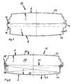
- FIG. 1 a housing part 10 is shown in section.
- the housing entire part 10 is in a mold cavity mold (not shown) made in one piece as a large hollow part, wherein it has a wall thickness s.
- the wall thickness s is almost constant in the housing entire part 10, wherein it extends between an outer side A and an inner side I.
- the entire housing part 10 has an area which forms the lower housing part 11. Another area forms the upper housing part 12.
- the two housing parts 11, 12 are connected along the dash-dotted line with a waste piece 13.
- the geometries of the housing parts 11, 12 are designed such that they can mesh with each other after the removal of the waste piece 13 and sealingly connected to each other.
- the lower housing part 11 on an insert 14, which is geometrically formed by the outer side A of the lower housing part 11.
- the upper housing part 12 has a receptacle 15, which after removing the waste piece 13 receives the insert 14.
- the receptacle 15 is geometrically formed by the inner side I of the upper housing part 12.
- FIG. 2 a filter housing 16 is shown in section. Of the FIG. 1 corresponding components are provided with the same reference numerals.
- the filter housing 16 has the upper housing part 12 and the lower housing part 11.
- a filter element 17 is introduced in the lower housing part 11.
- the filter element 17 is sealingly introduced between the lower housing part 11 and the upper housing part 12, whereby a raw area 18 is separated from a clean area 19.
- the raw area 18 is arranged in the upper housing part 12, this having an inlet 20, which was introduced by mechanical processing in the upper housing part 12 has.
- the clean area 19 is arranged in the lower housing part 11, wherein the lower housing part 11 has an outlet 21, which was also produced by a mechanical processing of the lower housing part 11.
- the inlet 20 or outlet 21 can of course also be formed by a special geometry of the mold cavity mold during the production of the housing part.
- the fluid to be cleaned flows in the direction of the arrow through the inlet 20 into the filter housing 16, is cleaned by the filter element 17 and then flows out through the outlet 21, also in the direction of arrow, from the filter housing 16 again.
- FIG. 3 is a double-walled upper housing part 12 'shown in section.
- the outer side A is designed such that it encloses the inner side I on all sides.
- the upper housing part 12 'on all sides over a, by the mold cavity form geometrically defined outside A, which has low tolerances. Due to these small tolerances, the insert 14 'is geometrically defined exactly and is not subject to the wall thickness fluctuations of the housing part 12'.
- the inner side I encloses a closed inner volume 22, which is not flowed through.
- This interior volume 22 has acoustic properties that can dampen the intake noise of an internal combustion engine.
- this upper housing part 12 'by its double-walled design has a higher rigidity.
- FIG. 4 the lower housing part 11 'is shown, which is also double-walled.
- corresponding components are provided with the same reference numerals, the comments on the outside A, inside I and inner volume 22 also apply to the lower housing part 11 '.
- the receptacle 15 ' is, as the insert 14' according to FIG. 3 completely formed by the outside A.
- the receptacle 15 ' has an exactly geometrically defined contour.
- a filter element (not shown) can be used and fixed by the insert 14' of the upper housing part 12 '.
Landscapes
- Engineering & Computer Science (AREA)
- Mechanical Engineering (AREA)
- Chemical & Material Sciences (AREA)
- Chemical Kinetics & Catalysis (AREA)
- Combustion & Propulsion (AREA)
- General Engineering & Computer Science (AREA)
- Filtering Of Dispersed Particles In Gases (AREA)
- Filtering Materials (AREA)
- Glass Compositions (AREA)
- Moulding By Coating Moulds (AREA)
Description
- Die vorliegende Erfindung betrifft ein Filtergehäuse und ein Herstellverfahren für ein Filtergehäuse. Insbesondere betrifft die Erfindung ein Filtergehäuse für einen Luftfilter für die Ansaugluft einer Brennkraftmaschine.
- Filtergehäuse werden typischerweise durch das Spritzgießverfahren hergestellt. Beim Spritzgießen werden dabei Ober- und Unterteil des Gehäuses mit getrennten Werkzeugen hergestellt. Die thermoplastischen Formmassen (Pulver, Körner, Würfel, Pasten etc.) werden dabei bis zur Verflüssigung (ca. 180°C) erwärmt und anschließend unter hohem Druck (bis 1400 bar) in geschlossene, zweiteilige, stählerne, wassergekühlte Werkzeughohlformen gespritzt, wo sie abkühlen und erstarren. Als Formmassen werden Polystyrol, Polyamide, Polyurethane, Celluloseether und -ester, Polyethylen, Polymethacrylsäureester und andere Thermoplaste, im Werkzeug aushärtende Duroplaste bzw. vulkanisierende Elastomere aus Kautschuk oder Siliconkautschuk und teilweise auch Schaumkunststoffe eingesetzt.
- Bei Luftfiltergehäusen muss eine gute Abdichtung der beiden Gehäuseteile gewährleistet sein, damit keine ungereinigte Luft von dem Rohluftbereich in den Reinluftbereich einströmen kann. Aber auch bei anderen Anwendungen ist es zweckmäßig und vorteilhaft, ein Gehäuse möglichst luftdicht mit einem Deckel zu verschließen. Hierzu werden üblicherweise Dichtungen verwendet, die im Bereich der Kontaktfläche zwischen Deckel und Gehäuseschale angeordnet sind. Gerade bei Kunststoffgehäusen besteht die Gefahr, dass sich das Material beim Herstellen des Gehäuses verzieht, wobei die Toleranzen dabei unter Umständen Undichtigkeiten zwischen den beiden Gehäuseteilen hervorrufen können.
- Die bisher bekannten Maßnahmen zur Vermeidung von Undichtigkeiten bestanden darin, dass die Teile im Dichtbereich verstärkt wurden, z. B. durch Materialanhäufungen oder durch den Einsatz von Versteifungselementen, die u. U. aus einem metallischen Material bestanden. Die Anwendung von Materialanhäufung führt jedoch dazu, dass gerade bei Kunststoff ein noch stärkerer Verzug eintritt. Die Verwendung von metallischen Versteifungselementen hingegen hat den Nachteil, dass ein Recycling des Kunststoffs nicht möglich ist bzw. in nicht unerheblichem Masse erschwert wird.
- In der
EP 0726389 B wurde daher bereits vorgeschlagen, ein Teil oder beide Kunststoffteile mit wenigstens einem allseitig geschlossenen Kanal zu versehen, welcher die Festigkeit sowie die maximale Biegespannung erhöht. Dieser Kanal wird dabei im Gasinnendruckverfahren hergestellt. Bei diesem Verfahren kann in einem einzigen Spritzgießvorgang zunächst das Kunststoffmaterial in die Spritzgießform eingebracht und anschließend durch die Spritzgießdüse oder durch eine weitere Düse Luft in den zu bildenden Kanal eingeblasen werden, wodurch sich ein luftführender Kanal ausbildet. - Auch dieses Verfahren bedingt jedoch aufgrund der Anwendung des Spritzgussverfahrens zwei getrennte Werkzeuge für Ober- und Unterteil des Filtergehäuses, wobei die Werkzeuge durch die Luftdüse sehr teuer sind.
- Aus der
EP 0767309 A1 ist ferner ein Verfahren zur Herstellung eines Dachventilatorgehäuses mittels Schleuderguß bekannt. - Aufgabe der vorliegenden Erfindung ist es daher, ein Filtergehäuse und Verfahren zur Herstellung von Filtergehäusen bereitzustellen, wobei das Filtergehäuse über eine ausreichende Dichtigkeit und Steifigkeit verfügt und mit Hilfe eines Werkzeugs einfach und kostengünstig herstellbar ist.
- Diese Aufgabe wird durch die Merkmale des Anspruchs 1 gelöst. Offenbarung der Erfindung
- Das erfindungsgemäße Filtergehäuse verfügt über ein oberes und ein unteres Gehäuseteil, wobei die beiden Gehäuseteile dichtend miteinander verbindbar sind. Die Verbindung der Gehäuseteile miteinander kann z. B. durch Schrauben oder Schnapphaken erzeugt sein, wobei selbstverständlich auch alle übrigen, im Stand der Technik bekannten Verbindungsarten verwendet werden können. Zwischen den Gehäuseteilen kann eine Dichtung angeordnet sein, welche die Abdichtung der Gehäuseteile erzeugt. Hierbei liegt die Dichtung an beiden Gehäuseteilen an. In das Filtergehäuse kann ein Filterelement eingesetzt werden, welches einen von dem Filtergehäuse umschlossenen Rohbereich dichtend von einem ebenfalls von dem Gehäuse umschlossenen Reinbereich trennt. Durch das Filterelement wird ein gasförmiges oder flüssiges Fluid gereinigt. Derartige Fluide können z. B. Luft für den Innenraum eines Kraftfahrzeugs oder die Ansaugluft für eine Brennkraftmaschine sein. Die Gehäuseteile sind im Schleudergussverfahren hergestellt, wobei sie über eine geometrisch definierte Außenseite und eine geometrisch undefinierte Innenseite verfügen. Die Außenseite verfügt durch einen direkten Werkzeugkontakt über relativ geringe Toleranzen. Die Innenseite des Gehäuseteils kontaktiert das Werkzeug während der Herstellung nicht, sie ergibt sich durch die Wandstärke und die Kontur der Außenseite. Daher verfügt die Innenseite über relativ große Toleranzen. Die geometrisch definierte Außenseite des einen Gehäuseteils ist mit der Außen- oder Innenseite des anderen Gehäuseteils verbunden. Hierbei verfügen die beiden Gehäuseteile über je einen Dichtbereich, welcher derart ausgestaltet ist, dass das jeweils andere Teil mit dem Dichtbereich kommunizieren kann. Vorzugsweise ist der Dichtbereich bei dem einen Gehäuseteil als Aufnahme und bei dem anderen Gehäuseteil als Einsatz ausgestaltet. Die Aufnahme kann sowohl durch die Außenseite, als auch durch die Innenseite gebildet sein. Der Einsatz ist der Bereich des Gehäuseteils, welcher in die Aufnahme eingreift. Dieser Einsatz kann ebenfalls durch die Außenseite und/oder die Innenseite gebildet sein. Somit wird eine ausreichende Dichtheit des Filtergehäuses erzielt. Da die Teile im Schleudergussverfahren hergestellt sind, sind die Werkzeugkosten nicht so hoch wie beim Spritzgussverfahren, was für Klein- und Kleinstserien vorteilhaft ist. Weiterhin können auch sehr großvolumige Gehäuseteile, wie z.B. Ansaugvorrichtungen von Nutzfahrzeugen, kostengünstig hergestellt werden.
- Erfindungsgemäß ist das untere Gehäuseteil einteilig mit dem oberen Gehäuseteil im Schleuderguss hergestellt. Die beiden Gehäuseteile werden nach der Entnahme aus dem Werkzeug mechanisch voneinander getrennt. Hierbei kann auch ein Abfallstück zwischen den beiden Gehäuseteilen herausgetrennt werden. Der Vorteil dieser Ausgestaltung besteht darin, dass durch die gleichzeitige Herstellung beider Gehäuseteile einerseits die Herstellkosten geringer sind als bei zwei getrennten Arbeitsabläufen, andererseits sind die Geometrien der Außen- und Innenseite aufeinander abgestimmt, wodurch eine optimale Passform und somit Dichtheit erzielt wird.
- Das erfindungsgemäße Verfahren zur Herstellung eines Filtergehäuses weist zumindest die Arbeitsschritte Einfüllen eines Kunststoffpulvers in eine Werkzeughohlform, Erhitzen, Rotieren, Abkühlen und Öffnen der Werkzeughohlform auf. Nach dem Öffnen der Werkzeughohlform wird das hergestellte Gehäuseteil entformt. Die hergestellten Gehäuseteile werden anschließend miteinander verbunden, wobei die Außenseite des einen Gehäuseteils mit der Außen- oder Innenseite des anderen Gehäuseteils verbunden wird. Durch dieses Verfahren sind Gehäuseteile mit geringen Kosten, guter Passform und somit Dichtheit herstellbar.
- Beim Einfüllen des Kunststoffpulvers wird eine exakt dosierte Menge in die Werkzeughohlform eingebracht, wobei das Kunststoffpulver z. B. pulvrig oder körnig sein kann. Weiterhin kann das Kunststoffpulver auch über eine sonstige Konsistenz, z. B. flüssig, verfügen, welche als Kunststoffformmasse geeignet ist. Dem Kunststoffpulver können noch Füllstoffe, wie z. B. Ruß, Kohlefasern, Glaskugeln oder - fasern beigemischt sein, welche die mechanische Steifigkeit des zu erzeugenden Bauteils erhöhen bzw. die chemische Beständigkeit verbessern. Die Menge des einzubringenden Kunststoffpulvers richtet sich nach der Größe und der Wandstärke des zu erzeugenden Bauteils. Als Material für das Filtergehäuse eignet sich z. B. Polyamid. Dieses Material ist insbesondere für Filtergehäuse von Kraftfahrzeugen geeignet, da dieses Material preiswert und für die Bedingungen in Kraftfahrzeugen geeignet ist. Vor dem Einfüllen des Kunststoffpulvers kann die Werkzeughohlform mit einem Trennmittel besprüht oder bestrichen werden, damit das fertige Kunststoffteil leichter aus der Werkzeughohlform entnommen werden kann. Die Werkzeughohlform kann z. B. aus Aluminiumguss, Stahlblech oder elektrisch aufgebrachtem Nickel bzw. Kupfer bestehen. Die Werkzeughohlform, welche mit ihrer Innenfläche die Außenkontur des zu erzeugenden Bauteils bildet, wird erhitzt. Das Erhitzen kann durch eine, in die Werkzeughohlform integrierte Heizung oder durch die Wärmezuführung von außen erfolgen. Eine in die Werkzeughohlform, insbesondere die Wandung der Werkzeughohlform integrierte Heizung kann z. B. über Heizdrähte verfügen. Die Werkzeughohlform ist auf eine Temperatur zu erhitzen, bei welcher das eingefüllte Kunststoffpulver schmilzt und sich durch das Rotieren der Werkzeughohlform um die Polar- und Äquatorialachse auf der Innenfläche der Werkzeughohlform gleichmäßig verteilt. Hierbei kann die Werkzeughohlform z. B. mit ca. 5 Umdrehungen/min rotiert werden. Somit können nahezu gleichmäßige Wandstärken bei dem Bauteil erzeugt werden. Wenn das ganze Kunststoffpulver aufgeschmolzen und in der Werkzeughohlform gleichmäßig verteilt ist, wird die Werkzeughohlform wieder abgekühlt, so dass die Schmelze erstarren und das Bauteil bilden kann. Das Abkühlen der Werkzeughohlform ist derart zu steuern, dass das Bauteil gleichmäßig abgekühlt wird, wodurch ein zu großer Verzug durch die Schwindung vermieden wird. Wenn das Bauteil ausreichend abgekühlt ist, kann die Werkzeughohlform an dafür vorgesehenen Formtrennungen geöffnet und das Bauteil entnommen werden. Nach dem vollständigen Erkalten des Bauteils können die Gehäuseteile zu dem Filtergehäuse zusammenmontiert werden, wobei ggf. noch eine mechanische Bearbeitung der Gehäuseteile erfolgen kann. Eine derartige Bearbeitung kann z. B. die Erzeugung einer Öffnung für den Einlass oder Auslass des zu reinigenden Fluids sein. Bei der Montage wird die Außenseite des einen Bauteils auf die Innen- oder Außenseite des anderen Bauteils montiert, wodurch eine optimale Abdichtung der Bauteile zueinander erzielt wird.
- Bauteile, welche im Schleudergussverfahren hergestellt sind, stehen während des Herstellungsvorgangs nur mit ihrer Außenseite in Kontakt mit der Werkzeughohlform. Die Innenseite des Bauteils verfügt über keinen direkten Kontakt zu der Werkzeughohlform, daher ergibt sich die Innenseite ohne eine definierte Formgebung.
- Bei der erfindungsgemäßen Ausgestaltung des Verfahrens werden beide Gehäuseteile einteilig in einer einzigen Werkzeughohlform hergestellt. Nach dem Entformen des Gehäusegesamtteils wird dieses in zwei oder mehr Gehäuseteile getrennt. Durch diese Trennung werden die einzelnen Gehäuseteile erzeugt. Bei der Trennung der Gehäuseteile können Abfallstücke entstehen, welche bei der Herstellung des Gehäusegesamtteils die einzelnen Gehäuseteile verbunden haben. Diese Abfallstücke haben bei der Herstellung des Gesamtgehäuseteils lediglich die Aufgabe die beiden Gehäuseteile miteinander zu verbinden, wobei der Übergang zwischen den Gehäuseteilen derart ausgebildet ist, dass die in der Werkzeughohlform enthaltene Schmelze an jede Stelle fließen kann. Große Absätze sind hierbei zu vermeiden.
- Es ist vorteilhaft, dass als Kunststoffpulver Polyethylen oder Polypropylen verwendet wird. Diese Materialien sind sehr preiswert und lassen sich einfach im Schleudergussverfahren verarbeiten. Weiterhin sind diese Materialien wasserresistent.
- Bei einer besonderen Ausgestaltung der Erfindung werden die Gehäuseteile mit Spannhaken, Schrauben oder dergleichen miteinander verbunden. Durch die lösbare Verbindung der Gehäuseteile kann das in dem Filtergehäuse eingebrachte Filterelement einfach gewechselt werden.
- Weitere Einzelheiten der Erfindung werden nachfolgend anhand der Figuren erläutert. Hierbei zeigt
- Figur 1
- eine schematische Darstellung eines Gehäusegesamtteils im Schnitt,
- Figur 2
- ein Filtergehäuse im Schnitt,
- Figur 3
- ein doppelwandiges oberes Gehäuseteil im Schnitt und
- Figur 4
- ein doppelwandiges unteres Gehäuseteil im Schnitt.
- In
Figur 1 ist ein Gehäusegesamtteil 10 im Schnitt dargestellt. Das Gehäusegesamtteil 10 ist in einer Werkzeughohlform (nicht dargestellt) einstückig als großes Hohlteil hergestellt, wobei es über eine Wandstärke s verfügt. Die Wandstärke s ist in dem Gehäusegesamtteil 10 nahezu konstant, wobei sie sich zwischen einer Außenseite A und einer Innenseite I erstreckt. Das Gehäusegesamtteil 10 verfügt über einen Bereich, welcher das untere Gehäuseteil 11 bildet. Ein anderer Bereich bildet das obere Gehäuseteil 12. Die beiden Gehäuseteile 11, 12 sind entlang der strich-punktierten Linie mit einem Abfallstück 13 verbunden. Die Geometrien der Gehäuseteile 11, 12 sind derart ausgelegt, dass diese nach dem Entfernen des Abfallstückes 13 ineinandergreifen und dichtend miteinander verbunden werden können. Hierzu weist das untere Gehäuseteil 11 einen Einsatz 14 auf, welcher geometrisch durch die Außenseite A des unteren Gehäuseteils 11 gebildet wird. Das obere Gehäuseteil 12 verfügt über eine Aufnahme 15, welche nach dem Entfernen des Abfallstückes 13 den Einsatz 14 aufnimmt. Die Aufnahme 15 wird geometrisch durch die Innenseite I des oberen Gehäuseteils 12 gebildet. - In
Figur 2 ist ein Filtergehäuse 16 im Schnitt dargestellt. DerFigur 1 entsprechende Bauteile sind mit gleichen Bezugszeichen versehen. Das Filtergehäuse 16 verfügt über das obere Gehäuseteil 12 und das untere Gehäuseteil 11. In das untere Gehäuseteil 11 ist ein Filterelement 17 eingebracht. Das Filterelement 17 ist dichtend zwischen das untere Gehäuseteil 11 und das obere Gehäuseteil 12 eingebracht, wodurch ein Rohbereich 18 von einem Reinbereich 19 getrennt wird. Der Rohbereich 18 ist in dem oberen Gehäuseteil 12 angeordnet, wobei dieses über einen Einlass 20, welcher durch eine mechanische Bearbeitung in das obere Gehäuseteil 12 eingebracht wurde, verfügt. Der Reinbereich 19 ist in dem unteren Gehäuseteil 11 angeordnet, wobei das untere Gehäuseteil 11 über einen Auslass 21 verfügt, welcher ebenfalls durch eine mechanische Bearbeitung des unteren Gehäuseteils 11 erzeugt wurde. Der Einlass 20 bzw. Auslass 21 kann selbstverständlich auch durch eine spezielle Geometrie der Werkzeughohlform bei der Herstellung des Gehäuseteils gebildet werden. Das zu reinigende Fluid strömt in Pfeilrichtung durch den Einlass 20 in das Filtergehäuse 16 ein, wird durch das Filterelement 17 gereinigt und strömt anschließend durch den Auslass 21, ebenfalls in Pfeilrichtung, aus dem Filtergehäuse 16 wieder aus. - In
Figur 3 ist ein doppelwandiges oberes Gehäuseteil 12' im Schnitt dargestellt. Bei diesem oberen Gehäuseteil 12' ist die Außenseite A derart ausgestaltet, dass sie die Innenseite I allseitig umschließt. Somit verfügt das obere Gehäuseteil 12' allseitig über eine, durch die Werkzeughohlform geometrisch definierte Außenseite A, welche über geringe Toleranzen verfügt. Durch diese geringen Toleranzen ist der Einsatz 14' geometrisch exakt definiert und unterliegt nicht den Wandstärkenschwankungen des Gehäuseteils 12'. Die Innenseite I umschließt ein abgeschlossenes Innenvolumen 22, welches nicht durchströmt wird. Dieses Innenvolumen 22 besitzt akustische Eigenschaften, welche die Ansauggeräusche einer Brennkraftmaschine dämpfen kann. Weiterhin besitzt dieses obere Gehäuseteil 12' durch seine doppelwandige Ausführung eine höhere Steifigkeit. - In
Figur 4 ist das untere Gehäuseteil 11' dargestellt, welches ebenfalls doppelwandig ausgeführt ist. DerFigur 3 entsprechende Bauteile sind mit gleichen Bezugszeichen versehen, wobei die Ausführungen zur Außenseite A, Innenseite I und Innenvolumen 22 auch für das untere Gehäuseteil 11' gelten. Die Aufnahme 15' ist, wie der Einsatz 14' gemäßFigur 3 , vollständig durch die Außenseite A gebildet. Somit verfügt die Aufnahme 15' über eine exakt geometrisch definierte Kontur. In diese Aufnahme 15' kann ein Filterelement (nicht dargestellt) eingesetzt und durch den Einsatz 14' des oberen Gehäuseteils 12' fixiert werden.
Claims (4)
- Verfahren zur Herstellung eines Filtergehäuses mit Filterelement (17), aufweisend zumindest folgende Arbeitsschritte: Einfüllen eines Kunststoffpulvers in eine Werkzeughohlform, wobei die Werkzeughohlform dem herzustellenden Gehäuseteil entspricht, Erhitzen der Werkzeughohlform, Rotieren der Werkzeughohlform um die Äquatorial- und Polarachsen, Abkühlen und Öffnen der Werkzeughohlform, und Entformung des Gehäuseteils (11, 12), wobei die beiden Gehäuseteile (12) und (11) miteinander verbunden werden, wobei die Außenseite (A) zumindest eines Gehäuseteils (11, 12) mit der Außen- oder Innenseite (A), (I) des anderen Gehäuseteils (11, 12) verbunden wird,
dadurch gekennzeichnet, dass beide Gehäuseteile (11, 12) einteilig, bei einem Arbeitsgang hergestellt werden, wobei das Abkühlen so gesteuert wird, dass das Bauteil gleichmäßig abgekühlt wird und nach dem Entformen in zwei oder mehrere Teile getrennt werden, wobei die Gehäuseteile (11, 12) gebildet und anschließend die Gehäuseteile (11, 12) miteinander verbunden werden, derart, daß das Filterelement (17) dichtend zwischen das untere Gehäuseteil (11) und das obere Gehäuseteil (12) eingebracht wird, wodurch ein Rohbereich (18) von einem Reinbereich (19) getrennt wird. - Verfahren nach Anspruch 1, dadurch gekennzeichnet, dass zwischen den Gehäuseteilen (11, 12) ein Abfallstück (13) herausgetrennt wird.
- Verfahren nach einem der vorhergehenden Ansprüche, dadurch gekennzeichnet, dass als Kunststoffpulver Polyethylen oder Polypropylen verwendet wird.
- Verfahren nach einem der vorhergehenden Ansprüche, dadurch gekennzeichnet, dass die Gehäuseteile (11, 12) mit Spannhaken, Schrauben oder dgl. miteinander verbunden werden.
Applications Claiming Priority (2)
| Application Number | Priority Date | Filing Date | Title |
|---|---|---|---|
| DE10360230A DE10360230A1 (de) | 2003-12-20 | 2003-12-20 | Herstellverfahren für Filtergehäuse |
| PCT/EP2004/053600 WO2005061880A1 (de) | 2003-12-20 | 2004-12-20 | Filtergehäuse und herstellverfahren für filtergehäuse |
Publications (2)
| Publication Number | Publication Date |
|---|---|
| EP1702154A1 EP1702154A1 (de) | 2006-09-20 |
| EP1702154B1 true EP1702154B1 (de) | 2011-03-23 |
Family
ID=34683703
Family Applications (1)
| Application Number | Title | Priority Date | Filing Date |
|---|---|---|---|
| EP04804936A Not-in-force EP1702154B1 (de) | 2003-12-20 | 2004-12-20 | Filtergeh use und herstellverfahren f r filtergeh use |
Country Status (7)
| Country | Link |
|---|---|
| US (1) | US20080157420A1 (de) |
| EP (1) | EP1702154B1 (de) |
| JP (1) | JP2007515587A (de) |
| AT (1) | ATE503103T1 (de) |
| BR (1) | BRPI0417835A (de) |
| DE (2) | DE10360230A1 (de) |
| WO (1) | WO2005061880A1 (de) |
Families Citing this family (3)
| Publication number | Priority date | Publication date | Assignee | Title |
|---|---|---|---|---|
| DE202007018599U1 (de) * | 2007-12-17 | 2009-01-08 | Carl Freudenberg Kg | Filtergehäuse für ein stationäres Aggregat |
| WO2016120199A1 (en) * | 2015-01-27 | 2016-08-04 | Airopack Technology Group B.V. | Pressure control system |
| WO2022067115A1 (en) * | 2020-09-24 | 2022-03-31 | Eisler John A | Lift system for contaminant mitigation |
Family Cites Families (12)
| Publication number | Priority date | Publication date | Assignee | Title |
|---|---|---|---|---|
| NL6706661A (de) * | 1966-05-26 | 1967-11-27 | ||
| SE359749B (de) * | 1972-01-26 | 1973-09-10 | Flodin B | |
| US4292015A (en) * | 1979-03-12 | 1981-09-29 | Michael Hritz | Apparatus for rotational molding |
| DE4141823C2 (de) * | 1991-12-18 | 1994-12-15 | Mann & Hummel Filter | Flüssigkeitsfilter |
| DE4218396B4 (de) * | 1992-06-04 | 2004-04-01 | Mann + Hummel Gmbh | Filtereinrichtung, insbesondere zum Filtrieren der Ansaugluft eines Verbrennungsmotors |
| AUPM399094A0 (en) * | 1994-02-18 | 1994-03-17 | Automated Plastic Systems Pty Ltd | Automatic rotamoulding apparatus and method of control |
| DE19539463B4 (de) * | 1995-02-08 | 2005-07-14 | Mann + Hummel Gmbh | Gehäuse, insbesondere für ein Luftfilter für die Ansaugluft einer Brennkraftmaschine |
| DE19529400C2 (de) | 1995-08-10 | 1997-05-15 | Funken & Co Gmbh | Verfahren zur Herstellung eines Dachventilatorgehäuses |
| GB9619126D0 (en) * | 1996-09-13 | 1996-10-23 | Rotational Mouldings Ltd | Acoustic hood |
| JPH1174337A (ja) * | 1997-08-28 | 1999-03-16 | Nippon Zeon Co Ltd | 熱可塑性樹脂製容器 |
| US20030090024A1 (en) * | 2001-11-14 | 2003-05-15 | Rubbermaid Incorporated | Method and apparatus for separating molded articles |
| US6692347B1 (en) * | 2002-09-27 | 2004-02-17 | L&L Products, Inc. | Filter housing assembly for transportation vehicles |
-
2003
- 2003-12-20 DE DE10360230A patent/DE10360230A1/de not_active Withdrawn
-
2004
- 2004-12-20 EP EP04804936A patent/EP1702154B1/de not_active Not-in-force
- 2004-12-20 AT AT04804936T patent/ATE503103T1/de active
- 2004-12-20 DE DE502004012337T patent/DE502004012337D1/de active Active
- 2004-12-20 WO PCT/EP2004/053600 patent/WO2005061880A1/de not_active Application Discontinuation
- 2004-12-20 JP JP2006544459A patent/JP2007515587A/ja active Pending
- 2004-12-20 BR BRPI0417835-1A patent/BRPI0417835A/pt not_active IP Right Cessation
-
2007
- 2007-06-21 US US11/766,554 patent/US20080157420A1/en not_active Abandoned
Also Published As
| Publication number | Publication date |
|---|---|
| DE502004012337D1 (de) | 2011-05-05 |
| JP2007515587A (ja) | 2007-06-14 |
| US20080157420A1 (en) | 2008-07-03 |
| BRPI0417835A (pt) | 2007-04-10 |
| DE10360230A1 (de) | 2005-07-21 |
| ATE503103T1 (de) | 2011-04-15 |
| WO2005061880A1 (de) | 2005-07-07 |
| EP1702154A1 (de) | 2006-09-20 |
Similar Documents
| Publication | Publication Date | Title |
|---|---|---|
| EP2507083B2 (de) | Filterelement und verfahren zum herstellen eines filterelements | |
| EP0726389B1 (de) | Gehäuse für Luftfilter einer Brennkraftmaschine | |
| DE10058478A1 (de) | Flaches Filterelement mit angegossenem Rahmen | |
| EP0824950A1 (de) | Filtereinsatz sowie Verfahren zu seiner Herstellung | |
| DE2620816A1 (de) | Kunststoff-formkoerper und verfahren zu seiner herstellung | |
| EP2334399B1 (de) | Verfahren zum herstellen einer filterendscheibe und eines fluidfilters, filterendscheibe | |
| EP2296776B1 (de) | Adapter zur befestigung eines filterelementes | |
| WO2018145810A1 (de) | Dichtungselement mit verblendleiste | |
| EP1527867A1 (de) | Verfahren zur Herstellung eines Lüfterrades sowie nach diesem Verfahren hergestelltes Lüfterrad | |
| EP1702154B1 (de) | Filtergeh use und herstellverfahren f r filtergeh use | |
| DE4420879A1 (de) | Herstellverfahren für einen Hohlkörper mit einem innenliegenden Stützrahmen | |
| DE102011111366A1 (de) | Filterelement und Verfahren zu dessen Herstellung | |
| DE102008014261A1 (de) | Verfahren und Gussform zur Herstellung eines zweiteiligen Schaumstoff-Verbundkörpers | |
| DE102016007944A1 (de) | Verfahren zur Herstellung eines polyurethanüberfluteten Bauteils | |
| DE102005006794B4 (de) | Mehrfachkomponenten-Spritzverfahren zur Bildung eines aus mehreren Komponenten bestehenden Körpers | |
| DE102005008686B4 (de) | Verfahren zur Herstellung von Fluid- oder Luftfiltern und damit hergestellte Filter | |
| EP3009250B1 (de) | Kunststoffspritzgusswerkzeug zur herstellung eines mehrkomponentenspritzgussbauteils | |
| DE1729108A1 (de) | Verfahren zum Herstellen von geschlossenen und offenen Behaeltern und Formteilen ausKunststoffen und auf diese Weise hergestellte Behaelter und Formteile | |
| EP0966862B1 (de) | Lautsprecher und verfahren zur herstellung eines lautsprechers | |
| EP1829669B1 (de) | Verfahren zur Herstellung einer Baueinheit aus mittels eines Filmscharniers miteinander verbundener Profilformteile und durch die Verfahren hergestellte Baueinheit | |
| EP1616142B1 (de) | Sammelkasten, wärmeübertrager und verfahren zur herstellung eines sammelkastens | |
| EP0767309B1 (de) | Verfahren zur Herstellung eines Dachventilatorgehäuses | |
| EP2982227B1 (de) | Verfahren und vorrichtung zur herstellung einer abdichtung zwischen einem träger eines elektrischen bauteils und einer den träger zumindest teilweise umgebenden umspritzung | |
| DE10315913A1 (de) | Hohlkörper aus Metall mit einer Innenauskleidung aus synthetischem Material und Vorrichtung zu deren Ausführung | |
| DE19518124C1 (de) | Vorrichtung zur Erzeugung von Formteilen aus thermoplastischem Kunststoff |
Legal Events
| Date | Code | Title | Description |
|---|---|---|---|
| PUAI | Public reference made under article 153(3) epc to a published international application that has entered the european phase |
Free format text: ORIGINAL CODE: 0009012 |
|
| 17P | Request for examination filed |
Effective date: 20060612 |
|
| AK | Designated contracting states |
Kind code of ref document: A1 Designated state(s): AT BE BG CH CY CZ DE DK EE ES FI FR GB GR HU IE IS IT LI LT LU MC NL PL PT RO SE SI SK TR |
|
| 17Q | First examination report despatched |
Effective date: 20061204 |
|
| DAX | Request for extension of the european patent (deleted) | ||
| GRAP | Despatch of communication of intention to grant a patent |
Free format text: ORIGINAL CODE: EPIDOSNIGR1 |
|
| GRAS | Grant fee paid |
Free format text: ORIGINAL CODE: EPIDOSNIGR3 |
|
| GRAA | (expected) grant |
Free format text: ORIGINAL CODE: 0009210 |
|
| AK | Designated contracting states |
Kind code of ref document: B1 Designated state(s): AT BE BG CH CY CZ DE DK EE ES FI FR GB GR HU IE IS IT LI LT LU MC NL PL PT RO SE SI SK TR |
|
| REG | Reference to a national code |
Ref country code: GB Ref legal event code: FG4D Free format text: NOT ENGLISH |
|
| REG | Reference to a national code |
Ref country code: CH Ref legal event code: EP |
|
| REG | Reference to a national code |
Ref country code: IE Ref legal event code: FG4D |
|
| REF | Corresponds to: |
Ref document number: 502004012337 Country of ref document: DE Date of ref document: 20110505 Kind code of ref document: P |
|
| REG | Reference to a national code |
Ref country code: DE Ref legal event code: R096 Ref document number: 502004012337 Country of ref document: DE Effective date: 20110505 |
|
| REG | Reference to a national code |
Ref country code: NL Ref legal event code: VDEP Effective date: 20110323 |
|
| PG25 | Lapsed in a contracting state [announced via postgrant information from national office to epo] |
Ref country code: SE Free format text: LAPSE BECAUSE OF FAILURE TO SUBMIT A TRANSLATION OF THE DESCRIPTION OR TO PAY THE FEE WITHIN THE PRESCRIBED TIME-LIMIT Effective date: 20110323 Ref country code: LT Free format text: LAPSE BECAUSE OF FAILURE TO SUBMIT A TRANSLATION OF THE DESCRIPTION OR TO PAY THE FEE WITHIN THE PRESCRIBED TIME-LIMIT Effective date: 20110323 Ref country code: GR Free format text: LAPSE BECAUSE OF FAILURE TO SUBMIT A TRANSLATION OF THE DESCRIPTION OR TO PAY THE FEE WITHIN THE PRESCRIBED TIME-LIMIT Effective date: 20110624 |
|
| LTIE | Lt: invalidation of european patent or patent extension |
Effective date: 20110323 |
|
| PG25 | Lapsed in a contracting state [announced via postgrant information from national office to epo] |
Ref country code: CY Free format text: LAPSE BECAUSE OF FAILURE TO SUBMIT A TRANSLATION OF THE DESCRIPTION OR TO PAY THE FEE WITHIN THE PRESCRIBED TIME-LIMIT Effective date: 20110323 Ref country code: SI Free format text: LAPSE BECAUSE OF FAILURE TO SUBMIT A TRANSLATION OF THE DESCRIPTION OR TO PAY THE FEE WITHIN THE PRESCRIBED TIME-LIMIT Effective date: 20110323 Ref country code: FI Free format text: LAPSE BECAUSE OF FAILURE TO SUBMIT A TRANSLATION OF THE DESCRIPTION OR TO PAY THE FEE WITHIN THE PRESCRIBED TIME-LIMIT Effective date: 20110323 Ref country code: BG Free format text: LAPSE BECAUSE OF FAILURE TO SUBMIT A TRANSLATION OF THE DESCRIPTION OR TO PAY THE FEE WITHIN THE PRESCRIBED TIME-LIMIT Effective date: 20110623 |
|
| REG | Reference to a national code |
Ref country code: IE Ref legal event code: FD4D |
|
| PG25 | Lapsed in a contracting state [announced via postgrant information from national office to epo] |
Ref country code: EE Free format text: LAPSE BECAUSE OF FAILURE TO SUBMIT A TRANSLATION OF THE DESCRIPTION OR TO PAY THE FEE WITHIN THE PRESCRIBED TIME-LIMIT Effective date: 20110323 Ref country code: PT Free format text: LAPSE BECAUSE OF FAILURE TO SUBMIT A TRANSLATION OF THE DESCRIPTION OR TO PAY THE FEE WITHIN THE PRESCRIBED TIME-LIMIT Effective date: 20110725 |
|
| PG25 | Lapsed in a contracting state [announced via postgrant information from national office to epo] |
Ref country code: SK Free format text: LAPSE BECAUSE OF FAILURE TO SUBMIT A TRANSLATION OF THE DESCRIPTION OR TO PAY THE FEE WITHIN THE PRESCRIBED TIME-LIMIT Effective date: 20110323 Ref country code: CZ Free format text: LAPSE BECAUSE OF FAILURE TO SUBMIT A TRANSLATION OF THE DESCRIPTION OR TO PAY THE FEE WITHIN THE PRESCRIBED TIME-LIMIT Effective date: 20110323 Ref country code: IS Free format text: LAPSE BECAUSE OF FAILURE TO SUBMIT A TRANSLATION OF THE DESCRIPTION OR TO PAY THE FEE WITHIN THE PRESCRIBED TIME-LIMIT Effective date: 20110723 Ref country code: RO Free format text: LAPSE BECAUSE OF FAILURE TO SUBMIT A TRANSLATION OF THE DESCRIPTION OR TO PAY THE FEE WITHIN THE PRESCRIBED TIME-LIMIT Effective date: 20110323 Ref country code: ES Free format text: LAPSE BECAUSE OF FAILURE TO SUBMIT A TRANSLATION OF THE DESCRIPTION OR TO PAY THE FEE WITHIN THE PRESCRIBED TIME-LIMIT Effective date: 20110704 |
|
| PG25 | Lapsed in a contracting state [announced via postgrant information from national office to epo] |
Ref country code: NL Free format text: LAPSE BECAUSE OF FAILURE TO SUBMIT A TRANSLATION OF THE DESCRIPTION OR TO PAY THE FEE WITHIN THE PRESCRIBED TIME-LIMIT Effective date: 20110323 |
|
| PLBE | No opposition filed within time limit |
Free format text: ORIGINAL CODE: 0009261 |
|
| STAA | Information on the status of an ep patent application or granted ep patent |
Free format text: STATUS: NO OPPOSITION FILED WITHIN TIME LIMIT |
|
| PG25 | Lapsed in a contracting state [announced via postgrant information from national office to epo] |
Ref country code: IE Free format text: LAPSE BECAUSE OF FAILURE TO SUBMIT A TRANSLATION OF THE DESCRIPTION OR TO PAY THE FEE WITHIN THE PRESCRIBED TIME-LIMIT Effective date: 20110323 |
|
| 26N | No opposition filed |
Effective date: 20111227 |
|
| PG25 | Lapsed in a contracting state [announced via postgrant information from national office to epo] |
Ref country code: DK Free format text: LAPSE BECAUSE OF FAILURE TO SUBMIT A TRANSLATION OF THE DESCRIPTION OR TO PAY THE FEE WITHIN THE PRESCRIBED TIME-LIMIT Effective date: 20110323 Ref country code: PL Free format text: LAPSE BECAUSE OF FAILURE TO SUBMIT A TRANSLATION OF THE DESCRIPTION OR TO PAY THE FEE WITHIN THE PRESCRIBED TIME-LIMIT Effective date: 20110323 |
|
| REG | Reference to a national code |
Ref country code: DE Ref legal event code: R097 Ref document number: 502004012337 Country of ref document: DE Effective date: 20111227 |
|
| PG25 | Lapsed in a contracting state [announced via postgrant information from national office to epo] |
Ref country code: IT Free format text: LAPSE BECAUSE OF FAILURE TO SUBMIT A TRANSLATION OF THE DESCRIPTION OR TO PAY THE FEE WITHIN THE PRESCRIBED TIME-LIMIT Effective date: 20110323 |
|
| BERE | Be: lapsed |
Owner name: MANN + HUMMEL G.M.B.H. Effective date: 20111231 |
|
| PG25 | Lapsed in a contracting state [announced via postgrant information from national office to epo] |
Ref country code: MC Free format text: LAPSE BECAUSE OF NON-PAYMENT OF DUE FEES Effective date: 20111231 |
|
| REG | Reference to a national code |
Ref country code: CH Ref legal event code: PL |
|
| GBPC | Gb: european patent ceased through non-payment of renewal fee |
Effective date: 20111220 |
|
| REG | Reference to a national code |
Ref country code: FR Ref legal event code: ST Effective date: 20120831 |
|
| PG25 | Lapsed in a contracting state [announced via postgrant information from national office to epo] |
Ref country code: GB Free format text: LAPSE BECAUSE OF NON-PAYMENT OF DUE FEES Effective date: 20111220 Ref country code: CH Free format text: LAPSE BECAUSE OF NON-PAYMENT OF DUE FEES Effective date: 20111231 Ref country code: LI Free format text: LAPSE BECAUSE OF NON-PAYMENT OF DUE FEES Effective date: 20111231 Ref country code: BE Free format text: LAPSE BECAUSE OF NON-PAYMENT OF DUE FEES Effective date: 20111231 |
|
| REG | Reference to a national code |
Ref country code: AT Ref legal event code: MM01 Ref document number: 503103 Country of ref document: AT Kind code of ref document: T Effective date: 20111220 |
|
| PG25 | Lapsed in a contracting state [announced via postgrant information from national office to epo] |
Ref country code: FR Free format text: LAPSE BECAUSE OF NON-PAYMENT OF DUE FEES Effective date: 20120102 |
|
| PG25 | Lapsed in a contracting state [announced via postgrant information from national office to epo] |
Ref country code: LU Free format text: LAPSE BECAUSE OF NON-PAYMENT OF DUE FEES Effective date: 20111220 |
|
| PG25 | Lapsed in a contracting state [announced via postgrant information from national office to epo] |
Ref country code: AT Free format text: LAPSE BECAUSE OF NON-PAYMENT OF DUE FEES Effective date: 20111220 |
|
| PG25 | Lapsed in a contracting state [announced via postgrant information from national office to epo] |
Ref country code: TR Free format text: LAPSE BECAUSE OF FAILURE TO SUBMIT A TRANSLATION OF THE DESCRIPTION OR TO PAY THE FEE WITHIN THE PRESCRIBED TIME-LIMIT Effective date: 20110323 |
|
| PG25 | Lapsed in a contracting state [announced via postgrant information from national office to epo] |
Ref country code: HU Free format text: LAPSE BECAUSE OF FAILURE TO SUBMIT A TRANSLATION OF THE DESCRIPTION OR TO PAY THE FEE WITHIN THE PRESCRIBED TIME-LIMIT Effective date: 20110323 |
|
| PGFP | Annual fee paid to national office [announced via postgrant information from national office to epo] |
Ref country code: DE Payment date: 20141211 Year of fee payment: 11 |
|
| REG | Reference to a national code |
Ref country code: DE Ref legal event code: R119 Ref document number: 502004012337 Country of ref document: DE |
|
| PG25 | Lapsed in a contracting state [announced via postgrant information from national office to epo] |
Ref country code: DE Free format text: LAPSE BECAUSE OF NON-PAYMENT OF DUE FEES Effective date: 20160701 |