EP1701833B1 - Direktangetriebener extruder mit adapter - Google Patents
Direktangetriebener extruder mit adapter Download PDFInfo
- Publication number
- EP1701833B1 EP1701833B1 EP04803236A EP04803236A EP1701833B1 EP 1701833 B1 EP1701833 B1 EP 1701833B1 EP 04803236 A EP04803236 A EP 04803236A EP 04803236 A EP04803236 A EP 04803236A EP 1701833 B1 EP1701833 B1 EP 1701833B1
- Authority
- EP
- European Patent Office
- Prior art keywords
- torque
- extruder
- rotor
- worm
- transmitting elements
- Prior art date
- Legal status (The legal status is an assumption and is not a legal conclusion. Google has not performed a legal analysis and makes no representation as to the accuracy of the status listed.)
- Not-in-force
Links
- 230000005540 biological transmission Effects 0.000 claims description 10
- 238000009420 retrofitting Methods 0.000 claims 1
- 238000001125 extrusion Methods 0.000 description 8
- 238000012423 maintenance Methods 0.000 description 2
- 238000005096 rolling process Methods 0.000 description 2
- 239000007787 solid Substances 0.000 description 2
- 230000006978 adaptation Effects 0.000 description 1
- 238000010276 construction Methods 0.000 description 1
- 230000001419 dependent effect Effects 0.000 description 1
- 238000006073 displacement reaction Methods 0.000 description 1
- 239000000428 dust Substances 0.000 description 1
Images


Classifications
-
- B—PERFORMING OPERATIONS; TRANSPORTING
- B29—WORKING OF PLASTICS; WORKING OF SUBSTANCES IN A PLASTIC STATE IN GENERAL
- B29C—SHAPING OR JOINING OF PLASTICS; SHAPING OF MATERIAL IN A PLASTIC STATE, NOT OTHERWISE PROVIDED FOR; AFTER-TREATMENT OF THE SHAPED PRODUCTS, e.g. REPAIRING
- B29C48/00—Extrusion moulding, i.e. expressing the moulding material through a die or nozzle which imparts the desired form; Apparatus therefor
- B29C48/25—Component parts, details or accessories; Auxiliary operations
- B29C48/36—Means for plasticising or homogenising the moulding material or forcing it through the nozzle or die
- B29C48/395—Means for plasticising or homogenising the moulding material or forcing it through the nozzle or die using screws surrounded by a cooperating barrel, e.g. single screw extruders
-
- B—PERFORMING OPERATIONS; TRANSPORTING
- B29—WORKING OF PLASTICS; WORKING OF SUBSTANCES IN A PLASTIC STATE IN GENERAL
- B29C—SHAPING OR JOINING OF PLASTICS; SHAPING OF MATERIAL IN A PLASTIC STATE, NOT OTHERWISE PROVIDED FOR; AFTER-TREATMENT OF THE SHAPED PRODUCTS, e.g. REPAIRING
- B29C48/00—Extrusion moulding, i.e. expressing the moulding material through a die or nozzle which imparts the desired form; Apparatus therefor
- B29C48/25—Component parts, details or accessories; Auxiliary operations
- B29C48/252—Drive or actuation means; Transmission means; Screw supporting means
-
- B—PERFORMING OPERATIONS; TRANSPORTING
- B29—WORKING OF PLASTICS; WORKING OF SUBSTANCES IN A PLASTIC STATE IN GENERAL
- B29C—SHAPING OR JOINING OF PLASTICS; SHAPING OF MATERIAL IN A PLASTIC STATE, NOT OTHERWISE PROVIDED FOR; AFTER-TREATMENT OF THE SHAPED PRODUCTS, e.g. REPAIRING
- B29C48/00—Extrusion moulding, i.e. expressing the moulding material through a die or nozzle which imparts the desired form; Apparatus therefor
- B29C48/03—Extrusion moulding, i.e. expressing the moulding material through a die or nozzle which imparts the desired form; Apparatus therefor characterised by the shape of the extruded material at extrusion
Definitions
- the invention relates to an extrusion device according to the preamble of claim 1.
- Ordinary extruding devices have an extruder screw driven by a worm gear via a gear.
- a gear device comprising a related art is in the patent US 3,802,670 disclosed.
- This document discloses a device with two extruder screws and a worm drive.
- the drive motor drives the two screws via a gear stage.
- detachable torque transmitting elements which transmit torque between the gear stage and the extruder screws and can be solved during retooling.
- the Drehmomeritübertragungsetti comprise a torque transmission point, is transmitted to the torque from a sleeve on one of the sleeve at least partially connecting portion.
- the EP 1 182 027 A1 a Extrusion device before, in which the extruder screw has a connection portion which is inserted into a sleeve and then rotatably connected thereto or is. Connecting portion and sleeve are surrounded by an already mentioned hollow shaft motor, which can give the drive torque generated it via Drehmomentübertragungsetemente on the sleeve. Due to the fact that the hollow shaft motor surrounds the connection section of the extruder screw, the entire extrusion device has a relatively short overall length.
- Object of the present invention is therefore to improve a known gearless extrusion device such that the torque transmitting elements are more accessible.
- connection section any continuation or extension of the extruder screw. It is irrelevant whether this connection portion is formed integrally with the extruder screw or mechanically connected thereto.
- the torque transmission elements between the extruder screw and the drive motor are arranged in order to use an extruder screw with the shortest possible connection section can.
- the torque transmission elements comprise an axially extending screw connection, with which the sleeve and the connecting portion are rotatably connected.
- the sleeve and the connection section can be quickly and easily separated from each other.
- This screw can be achieved by the hollow shaft of the drive motor easily.
- At least one of the torque transmission elements is at least partially surrounded by a housing which is fixedly connected to the housing of the extruder screw.
- a housing which is fixedly connected to the housing of the extruder screw.
- the housing of the drive motor with the housing can be releasably attached to this housing. All elements of the extrusion device then form a unit, which can then be designed, for example, movable.
- the bearings used are angular contact bearings that are able to absorb axial forces, but are self-centering.
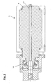
- the Fig. 1 shows an extruding device according to the invention, which consists of a drive motor 1, torque transmitting elements, which are indicated in its entirety by 2, and an extruder 3.
- the motor 1 consists of a stator 7, which is surrounded by a motor housing 12, and a rotor 8, which is supported via radial bearings 9 on the stator 7.
- the rotor 8 is a hollow shaft, so that it has a tubular interior 11.
- the rotor 8 further comprises a projection 10, which protrudes from the stator 7 and is surrounded by a housing projection 13.
- a sleeve 14 is frontally attached to the neck 10 of the rotor 8. This connection is rotatable and can be made via a screw, but also via a plug connection. This sleeve 14 surrounds the connecting portion 6 of the extruder screw 4.
- the torsional strength mainly by a tongue and groove System or equivalent system between terminal portion 6 and sleeve 14 is achieved.
- several screws can be provided.
- connection section 6 is supported on the sleeve 14 via ring stages in the axial direction, so that the sleeve 14 and the connection section 6 are axially immovable relative to one another.
- the connection of sleeve 14 and connecting portion 6 can be solved, for example, for maintenance.
- the extruder screw 4 can be pulled out after loosening the connection in the direction of the drive motor 6 from the extruder housing 5.
- the sleeve 14 and the connection section 6 are surrounded by a housing 16.
- the various housings 5, 13, 16 and 12 are connected to each other to form a housing unit.
- the housing 16 encloses a roller bearing 17, on which in turn the sleeve 14 is supported.
- a ring 18 is additionally attached, so that the sleeve 14 is mounted immovably relative to the housing 16.
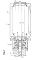
- the Fig. 2 shows an embodiment of the invention in which a drive motor 1 with a solid shaft, into which a tubular inner space 11 has been drilled, the diameter of which is sufficient to accommodate the screw 25, in contrast to in Fig. 1 shown screw 5 is long enough to pass through the drive motor 1 therethrough.
- the sleeve 14 and the rotor 8 are integrally formed in this embodiment. The function of the individual components remains in comparison to in Fig. 1 However, obtained embodiment shown.
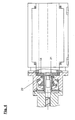
- the Fig. 3 shows one in comparison with the Fig. 1 very similar embodiment of the present invention.
- an intermediate sleeve 21 is rotatably mounted within the sleeve 14.
- the intermediate sleeve 21 can be screwed into the sleeve 14 or be connected via a tongue and groove system with this.
- the connection section 6 of the extruder screw 4 is supported by annular steps on the intermediate sleeve 21.
- the extruder screw 4 can be pulled out together with the intermediate sleeve 21 through the tubular interior 11 of the drive motor 1 from the extruder housing 5.
- the screw 15 has been replaced by a bolt 19.
- This bolt 19 extends at least through the entire tubular interior of the drive motor 1 and has analogous to the screw at one end a thread, so that with this bolt 19, a rotationally fixed connection between the connecting portion 6 of the extruder screw 4 and the sleeve 14 can be made.
- the bolt 19 may be made smaller at its end opposite the thread in its diameter. In this thinner portion, a sleeve 20 may be pushed, which in turn is attached to the motor housing 12. In this way, for the bolt 19 a Formed abutment, whereby the pin 19, the intermediate sleeve 21 can be supported.
- the Fig. 4 shows an extrusion device with an intermediate sleeve 21, as already in FIG. 3 has been shown.
- a retaining ring 22 is screwed into this.
- connection portion 6 and the sleeve 14 are connected by locking pins 24 against rotation. Since these locking pins 24 are axially displaceable, they are by the locking ring 23 which is secured in the sleeve 14, for example, screwed, is fixed. Subsequently, with the screw 15, the connection section can be connected to the sleeve.
Landscapes
- Engineering & Computer Science (AREA)
- Mechanical Engineering (AREA)
- Extrusion Moulding Of Plastics Or The Like (AREA)
Description
- Die Erfindung betrifft eine Extrudiervorrichtung gemäß dem Oberbegriff des Anspruchs 1.
- Gewöhnliche Extrudiervorrichtungen weisen eine Extruderschnecke auf, die von einem Schneckenantrieb über ein Getriebe angetrieben werden.
- Eine ein Getriebe umfassende Vorrichtung verwandter Art ist in der Patentschrift
US 3,802,670 offenbart. Diese Druckschrift offenbart eine Vorrichtung mit zwei Extruderschnecken und einem Schneckenantrieb. Der Antriebsmotor treibt über eine Getriebestufe die beiden Schnecken an. Es sind weiterhin lösbare Drehmomentübertragungselemente vorgesehen, welche zwischen der Getriebestufe und den Extruderschnecken Drehmoment übertragen und bei Umrüstarbeiten gelöst werden können. Die Drehmomeritübertragungselemente umfassen dabei eine Drehmomenfübertragungsstelle, an der Drehmoment von einer Hülse auf einen von der Hülse zumindest teilweise umfassen Anschlussabschnitt übertragen wird. - Solche Getriebe sind allerdings mechanisch kompliziert und wartungsintensiv, so dass man in jüngster Zeit bestrebt ist, Extruderschnecken direkt - das heißt ohne Getriebe - anzutreiben.
- Mit dem Aufkommen von so genannten Hohlwellenmotoren ist es nunmehr möglich, derartige direkt angetriebenen Extrudervorrichtungen mit kleineren Abmessungen zu bauen. So schlägt beispielsweise die
EP 1 182 027 A1 eine Extrusionsvorrichtung vor, bei der die Extruderschnecke einen Anschlussabschnitt aufweist, der in eine Hülse eingesteckt und mit dieser dann drehfest verbunden ist oder wird. Anschlussabschnitt und Hülse sind dabei von einem bereits erwähnten Hohlwellenmotor umgeben, welcher das ihm erzeugte Antriebsdrehmoment über Drehmomentübertragungsetemente auf die Hülse geben kann. Aufgrund der Tatsache, dass der Hohlwellenmotor den Anschlussabschnitt der Extruderschnecke umgibt, weist die gesamte Extrusionsvorrichtung eine relativ kurze Baulänge auf. - Nachteilig ist bei dieser Konstruktion allerdings, dass die Drehmomentübertragungselemente schwer zugänglich sind. Der Vorteil der etwas kürzeren Baulänge wird also durch länger andauernde Wartungsarbeit mehr als zunichte gemacht.
- Aufgabe der vorliegenden Erfindung ist es daher, eine bekannte getriebelose Extrusionsvorrichtung derart zu verbessern, dass die Drehmomentübertragungselemente leichter zugänglich sind.
- Die Aufgabe wird gelöst durch das Merkmal des kennzeichnenden Teils im Anspruch 1.
- Demnach liegen die Drehmomentübertragungselemente in axialer Richtung außerhalb des Rotors. Auf diese Weise können die Drehmomentübertragungselemente händisch erreicht werden, ohne den Hohlwellenmotor mit seinem äußeren Stator und den innenliegenden Rotor entfernen zu müssen. In der Sprache der vorliegenden Druckschrift wird unter Anschlussabschnitt jedwede Fortsetzung oder Verlängerung der Extruderschnecke verstanden. Hierbei ist es ohne Belang, ob dieser Anschlussabschnitt einstückig mit der Extruderschnecke ausgeprägt oder mechanisch mit dieser verbunden ist.
- In weiterer Ausgestaltung der Erfindung sind die Drehmomentübertragungselemente zwischen der Extruderschnecke und dem Antriebsmotor angeordnet, um eine Extruderschnecke mit einem möglichst kurzen Anschlussabschnitt einsetzen zu können.
- Vorteilhaft ist es, wenn die Drehmomentübertragungselemente eine axial verlaufende Schraubverbindung umfassen, mit welcher die Hülse und der Anschlussabschnitt drehfest verbindbar sind. In diesem Fall lassen sich die Hülse und der Anschlussabschnitt schnell und unkompliziert voneinander trennen. Diese Schraubverbindung kann durch die Hohlwelle des Antriebsmotors ohne weiteres erreicht werden.
- In einer weiteren vorteilhaften Ausgestaltung der Erfindung ist es vorgesehen, dass zumindest eines der Drehmomentübertragungselemente zumindest teilweise von einem Gehäuse umgeben ist, welches mit dem Gehäuse der Extruderschnecke fest verbunden ist. Damit ist es möglich, die Drehmomentübertragungselemente vor äußeren Störeinflüssen, wie etwa Staub, zu schützen. Zusätzlich kann an diesem Gehäuse auch das Gehäuse des Antriebsmotors mit dem Gehäuse lösbar angebracht sein. Sämtliche Elemente der Extrudiervorrichtung bilden dann eine Einheit, die dann beispielsweise bewegbar ausgestaltet sein kann.
- Weiterhin ist es besonders vorteilhaft, wenn sich eines der Drehmomentübertragungselemente mittels Wälz- und/oder Kugellagern an dem umgebenen Gehäuse abstützt. Versuche haben gezeigt, dass im Betrieb auf die Extruderschnecke erhebliche Kräfte wirken, die mit geeigneten Lagern abgefangen werden müssen. Werden handelsübliche Hohlwellenmotoren eingesetzt, deren Lager für die in Extrudern herrschenden Kräfte nicht ausgelegt sind, so ist mit häufigen Lagerschäden zu rechnen. Eine konstruktive Anpassung von Hohlwellenmotoren an die genannten Anforderungen würde hingegen zu sehr hohen Kosten führen, weshalb diese Lösung nachteilig wäre.
- Vorteilhafterweise sind die eingesetzten Wälzlager Schräglager, die in der Lage sind Axialkräfte aufzunehmen, dabei aber selbstzentrierend sind.
- Weitere Ausgestaltungen der Erfindung sind den Unteransprüchen und der Zeichnung zu entnehmen. Hierin zeigen:
- Fig. 1
- eine erfindungsgemäße Extrudiervorrichtung und
- Fig. 2
- eine erfindungsgemäße Extrudiervorrichtung mit einem Antriebsmotor mit Vollwelle
- Fig. 3
- eine gleichartige Extrudiervorrichtung mit zusätzlicher Buchse
- Fig. 4
- eine weitere Ausführungsform der erfindungsgemäßen Extrudiervorrichtung
- Fig. 5
- eine weitere Ausführungsform der erfindungsgemäßen Extrudiervorrichtung
- Die
Fig. 1 zeigt eine erfindungsgemäße Extrudiervorrichtung, die aus einem Antriebsmotor 1, Drehmomentübertragungselemente, die in ihrer Gesamtheit mit 2 bezeichnet sind, und einem Extruder 3. Der Extruder 3 besteht, wie in der Praxis üblich, im wesentlichen aus einer Extruderschnecke 4, welche in einem Extrudergehäuse 5 drehbar gelagert ist. Der Motor 1 besteht aus einem Stator 7, welcher von einem Motorgehäuse 12 umgeben ist, und einem Rotor 8, der sich über Radiallager 9 am Stator 7 abstützt. Der Rotor 8 ist hohlwellenartig, so dass er einen rohrförmigen Innenraum 11 aufweist. Der Rotor 8 umfasst weiterhin einen Ansatz 10, welcher aus dem Stator 7 herausragt und von einem Gehäuseansatz 13 umgeben ist. - Um das vom Antriebsmotor 1 erzeugte Drehmoment auf die Extruderschnecke 4 übertragen zu können, ist stirnseitig an dem Ansatz 10 des Rotors 8 eine Hülse 14 angebracht. Diese Verbindung ist drehfest und kann über eine Schraub-, aber auch über eine Steckverbindung hergestellt werden. Diese Hülse 14 umschließt den Anschlussabschnitt 6 der Extruderschnecke 4. Zur Übertragung des an der Hülse 14 anliegenden Drehmoments auf die Extruderschnecke 4 ist deren Anschlussabschnitt 6 mit einer Schraube 15 an der Hülse 14 drehfest verschraubt, wobei die Drehfestigkeit vor allem durch ein Nut-Feder-System oder einem gleichwertigen System zwischen Anschlussabschnitt 6 und Hülse 14 erzielt wird. Selbstverständlich können auch mehrere Schrauben vorgesehen sein. Diese Schrauben 15 lassen sich von der dem Extruder 3 abgewandten Seite des Antriebsmotors 1 durch dessen rohrförmigen Innenraum 11 bequem erreichen. Der Anschlussabschnitt 6 stützt sich über Ringstufen in axialer Richtung auf der Hülse 14 ab, so dass die Hülse 14 und der Anschlussabschnitt 6 relativ zueinander axial unverschieblich sind. Die Verbindung von Hülse 14 und Anschlussabschnitt 6 kann so, beispielsweise für Wartungsarbeiten, gelöst werden. Die Extruderschnecke 4 kann nach Lösen der Verbindung in Richtung vom Antriebsmotor 6 aus dem Extrudergehäuse 5 herausgezogen werden.
- Die Hülse 14 und der Anschlussabschnitt 6 sind von einem Gehäuse 16 umgeben. Die verschiedenen Gehäuse 5, 13, 16 und 12 sind miteinander verbunden, so dass sie eine Gehäuseeinheit bilden. Das Gehäuse 16 umschließt ein Wälzlager 17, auf welchem sich wiederum die Hülse 14 abstützt. Auf der Hülse 14 ist zusätzlich ein Ring 18 befestigt, so dass die Hülse 14 gegenüber dem Gehäuse 16 unverschieblich gelagert ist. An dieser Stelle ist es erwähnenswert, dass im Betrieb der von der Extruderschnecke 4 ausgehende Druck in axialer Richtung zum Antrieb verläuft. Das Wälzlager 17 ist dazu in der Lager, die an der Extruderschnecke 4 auftretenden Axialkräfte abzufangen.
- Die
Fig. 2 zeigt eine Ausführungsform der Erfindung in der ein Antriebsmotor 1 mit einer Vollwelle, in die ein rohrförmiger Innenraum 11 gebohrt wurde, deren Durchmesser ausreichend ist, um die Schraube 25 aufzunehmen, die im Gegensatz zur inFig. 1 dargestellten Schraube 5 lang genug ist, um durch den Antriebsmotor 1 hindurch zu reichen. Die Hülse 14 und der Rotor 8 sind in diesem Ausführungsbeispiel einstückig ausgebildet. Die Funktion der einzelnen Bauteile bleibt im Vergleich zur inFig. 1 dargestellten Ausführungsform jedoch erhalten. - Die
Fig. 3 zeigt eine im Vergleich mit derFig. 1 sehr ähnliche Ausführungsform der vorliegenden Erfindung. In diesem Fall ist innerhalb der Hülse 14 eine Zwischenhülse 21 drehfest befestigt. Die Zwischenhülse 21 kann dabei in die Hülse 14 eingeschraubt oder über ein Nut-Feder-System mit dieser verbunden sein. Der Anschlussabschnitt 6 der Extruderschnecke 4 stützt sich dabei über Ringstufen an der Zwischenhülse 21 ab. Bei dieser Anordnung kann die Extruderschnecke 4 zusammen mit der Zwischenhülse 21 durch den rohrförmigen Innenraum 11 des Antriebsmotors 1 aus dem Extrudergehäuse 5 herausgezogen werden. Weiterhin ist im Vergleich mit dem inFig. 1 vorgestellten Ausführungsbeispiel die Schraube 15 durch einen Bolzen 19 ersetzt worden. Dieser Bolzen 19 reicht mindestens durch den gesamten rohrförmigen Innenraum des Antriebsmotors 1 und besitzt analog zur Schraube an einem Ende ein Gewinde, so dass mit diesem Bolzen 19 eine drehfeste Verbindung zwischen dem Anschlussabschnitt 6 der Extruderschnecke 4 und der Hülse 14 hergestellt werden kann. - Der Bolzen 19 kann an seinem dem Gewinde gegenüber liegenden Ende in seinem Durchmesser kleiner gestaltet sein. Auf diesen dünneren Abschnitt kann eine Buchse 20 aufgeschoben sein, welche wiederum an dem Motorgehäuse 12 befestigt ist. Auf diese Weise wird für den Bolzen 19 ein Widerlager gebildet, wodurch der Bolzen 19 die Zwischenhülse 21 abstützen kann.
- Die
Fig. 4 zeigt eine Extrudiervorrichtung mit einer Zwischenhülse 21, wie sie bereits inFigur 3 dargestellt worden ist. Zur Verhinderung der axialen Verschiebung der Zwischenhülse 21 innerhalb der Hülse 14 ist in diese ein Sicherungsring 22 eingeschraubt. - Die in
Fig. 5 gezeigte Extrudiervorrichtung ist ähnlich zu derjenigen, die inFig. 1 gezeigt ist. Hier sind der Anschlussabschnitt 6 und die Hülse 14 über Sicherungsstifte 24 verdrehsicher miteinander verbunden. Da diese Sicherungsstifte 24 axial verschieblich sind, werden diese durch die Sicherungsring 23, der in der Hülse 14 befestigt, beispielsweise eingeschraubt, ist, festgelegt. Anschließend kann mit der Schraube 15 der Anschlussabschnitt mit der Hülse verbunden werden. -
1 Antriebsmotor 2 Drehmomentübertragungselemente 3 Extruder 4 Extruderschnecke 5 Extrudergehäuse 6 Anschlussabschnitt 7 Stator 8 Rotor 9 Radiallager 10 Ansatz 11 rohrförmiger Innenraum 12 Motorgehäuse 13 Gehäuseansatz 14 Hülse 15 Schraube 16 Gehäuse 17 Wälzlager 18 Ring 19 Bolzen 20 Buchse 21 Zwischenhülse 22 Sicherungsring 23 Sicherungsring 24 Sicherungsstift 25 26 27 28 29 30
Claims (9)
- Extrudiervorrichtung mit einer Extruderschnecke (4) und einem Schneckenantrieb (1, 2),- welcher (1, 2) einen Antriebsmotor (1) umfasst,- welcher einen äußeren Stator und einen innenliegenden Rotor (8) aufweist,- welcher mit lösbaren Drehmomentübertragungselementen (6, 14, 15) verbindbar ist, welche zwischen dem Rotor (8) und der Extruderschnecke (4) Drehmoment übertragen und bei Umrüstarbeiten gelöst werden können,- wobei die lösbaren Drehmomentübertragungselemente (6, 14, 15) eine Drehmomentübertragungsatelle umfassen, an der Drehmoment von einer Hülse (14) auf einen von der Hülse (14) zumindest teilweise umfassten Anschlussabschnitt (6) übertragen wird,dadurch gekennzeichnet,- dass der Rotor (8) des Antriebsmotors (1) im Betrieb getriebelos mit der Extruderschnecke (4) verbunden ist, so dass sich im Betrieb Rotor (8) und Extruderschnecke (4) mit gleicher Drehzahl drehen,- dass die Hülse an einer Stirnseite des Rotors (8) des Antriebsmotors (1) befestigt ist und- dass die Drehmomentübertragungsstelle in axialer Richtung außerhalb des Rotors (8) liegt.
- Extrudiervorrichtung nach Anspruch 1,
dadurch gekennzeichnet, dass
sowohl Hülse als auch der Anschlussabschnitt vollständig außerhalb des Rotors liegen. - Extrudiervorrichtung nach einem der vorstehenden Ansprüche,
dadurch gekennzeichnet, dass
die Drehmomentübertragungselemente (6, 14, 15) zwischen dem Rotor (8) und der Extrudierschnecke (14) angeordnet sind. - Extrudiervorrichtung nach einem oder mehreren der vorstehenden Ansprüche,
dadurch gekennzeichnet, dass
die Drehmomentübertragungselemente (6, 14, 15) eine axial verlaufenden Schraubverbindung (15) umfassen, mit welcher die Hülse (14) und der Anschlussabschnitt (6) drehfest verbindbar sind. - Extrudiervorrichtung nach einem oder mehreren der vorstehenden Ansprüche,
dadurch gekennzeichnet, dass
zumindest eines der Drehmomentübertragungselemente (6, 14, 15) zumindest teilweise von einem Gehäuse (16), welches mit dem Gehäuse (5) der Extruderschnecke (4) fest verbunden ist, umgeben ist. - Extrudiervorrichtung nach Anspruch 5,
dadurch gekennzeichnet, dass
das Gehäuse (12) des Antriebsmotors (1) mit dem Gehäuse (16) lösbar verbunden ist, welches die Drehmomentüberiragungselemente (6, 14, 15) zumindest teilweise umgibt. - Extrudiervorrichtung nach Anspruch 5 oder 6,
dadurch gekennzeichnet, dass
sich zumindest eines der Drehmvmentübertragungselemente (6, 14, 15) mittels Wälz- und/oder Kugellager (17) an dem umgebenden Gehäuse (16) abstützt. - Extrudiervorrichtung nach vorstehendem Anspruch,
dadurch gekennzeichnet, dass
das Wälzlager (17) ein Schräglager ist, welches axiale Kräfte aufnehmen kann. - Extrudiervorrichtung nach einem der beiden vorstehenden Ansprüche,
dadurch gekennzeichnet, dass
dieses zumindest eine Drehmomentübertragungselement (6, 14, 15) die Hülse (14) ist.
Applications Claiming Priority (2)
| Application Number | Priority Date | Filing Date | Title |
|---|---|---|---|
| DE10357884A DE10357884A1 (de) | 2003-12-11 | 2003-12-11 | Direktangetriebener Extruder mit Adapter |
| PCT/EP2004/013293 WO2005058579A1 (de) | 2003-12-11 | 2004-11-24 | Direktangetriebener extruder mit adapter |
Publications (2)
| Publication Number | Publication Date |
|---|---|
| EP1701833A1 EP1701833A1 (de) | 2006-09-20 |
| EP1701833B1 true EP1701833B1 (de) | 2008-07-30 |
Family
ID=34683307
Family Applications (1)
| Application Number | Title | Priority Date | Filing Date |
|---|---|---|---|
| EP04803236A Not-in-force EP1701833B1 (de) | 2003-12-11 | 2004-11-24 | Direktangetriebener extruder mit adapter |
Country Status (6)
| Country | Link |
|---|---|
| US (1) | US7845844B2 (de) |
| EP (1) | EP1701833B1 (de) |
| AT (1) | ATE402804T1 (de) |
| CA (1) | CA2550139C (de) |
| DE (2) | DE10357884A1 (de) |
| WO (1) | WO2005058579A1 (de) |
Families Citing this family (6)
| Publication number | Priority date | Publication date | Assignee | Title |
|---|---|---|---|---|
| FR2918921B1 (fr) * | 2007-07-19 | 2009-09-18 | Ssd Parvex S A S | Dispositif d'extrusion a moteur couple |
| EP2120315B1 (de) | 2008-05-15 | 2014-02-26 | Siemens Aktiengesellschaft | Antriebseinrichtung |
| DE102008038939B3 (de) * | 2008-08-13 | 2010-04-15 | Kraussmaffei Berstorff Gmbh | Extrudiervorrichtung |
| CN104110485B (zh) * | 2014-06-15 | 2017-02-08 | 陈伟 | 风冷式塑料挤出机动平衡摆线减速箱 |
| CN104110486B (zh) * | 2014-06-15 | 2017-07-11 | 浙江恒齿传动机械有限公司 | 风冷式塑料挤出机动平衡少齿差减速箱 |
| CN112968572A (zh) * | 2021-03-29 | 2021-06-15 | 龚杰 | 一种具有可拆卸结构的空心直驱力矩电机 |
Family Cites Families (10)
| Publication number | Priority date | Publication date | Assignee | Title |
|---|---|---|---|---|
| US3802670A (en) | 1970-11-05 | 1974-04-09 | Japan Steel Works Ltd | Continuous mixer for thermoplastic resin |
| DE4430176A1 (de) | 1994-08-25 | 1996-02-29 | Krupp Maschinentechnik | Schneckenextruder |
| US5891485A (en) | 1997-05-30 | 1999-04-06 | Sumitomo Heavy Industries, Ltd. | Built-in motor type electric injection molding apparatus |
| ATE197571T1 (de) * | 1997-06-05 | 2000-12-15 | Sumitomo Heavy Industries | Spritzgiessmaschine vom typ mit eingebautem elektrischem motor |
| DE29910332U1 (de) * | 1999-06-10 | 2000-10-26 | Struckmeier Gmbh Antriebstechn | Elektrischer Antriebsmotor für Arbeitsmaschinen, insbesondere für Extruder oder Spritzgießmaschinen |
| EP1182027B2 (de) * | 2000-08-09 | 2006-11-22 | Reifenhäuser GmbH & Co. Maschinenfabrik | Extrudiervorrichtung |
| DE10132002C5 (de) * | 2001-07-03 | 2009-12-31 | Windmöller & Hölscher Kg | Direktangetriebener Extruder |
| DE10230876C5 (de) * | 2002-07-09 | 2009-09-10 | Siemens Ag | Antriebsvorrichtung für eine Kunststoffverarbeitungsmaschine |
| DE10320599B4 (de) * | 2003-05-08 | 2010-04-01 | Siemens Ag | Antriebsvorrichtung für Kunststoffextruder mit nach hinten herausnehmbarer Extruderschnecke |
| DE10329035A1 (de) * | 2003-06-27 | 2005-01-27 | Battenfeld Service Gmbh | Antrieb für eine Plastifiziereinheit |
-
2003
- 2003-12-11 DE DE10357884A patent/DE10357884A1/de not_active Ceased
-
2004
- 2004-11-24 AT AT04803236T patent/ATE402804T1/de active
- 2004-11-24 CA CA2550139A patent/CA2550139C/en not_active Expired - Fee Related
- 2004-11-24 WO PCT/EP2004/013293 patent/WO2005058579A1/de active IP Right Grant
- 2004-11-24 US US10/582,486 patent/US7845844B2/en not_active Expired - Fee Related
- 2004-11-24 DE DE502004007752T patent/DE502004007752D1/de active Active
- 2004-11-24 EP EP04803236A patent/EP1701833B1/de not_active Not-in-force
Also Published As
| Publication number | Publication date |
|---|---|
| CA2550139A1 (en) | 2005-06-30 |
| WO2005058579A1 (de) | 2005-06-30 |
| DE502004007752D1 (de) | 2008-09-11 |
| US7845844B2 (en) | 2010-12-07 |
| CA2550139C (en) | 2012-08-14 |
| ATE402804T1 (de) | 2008-08-15 |
| DE10357884A1 (de) | 2005-07-21 |
| US20070166421A1 (en) | 2007-07-19 |
| EP1701833A1 (de) | 2006-09-20 |
Similar Documents
| Publication | Publication Date | Title |
|---|---|---|
| EP0671569B1 (de) | Drehgelenkkupplung, insbesondere an einer Gelenkwelle einer Exzenterschneckenmaschine | |
| EP3388610A1 (de) | Wellenbaugruppe, verschluss- oder schutzeinrichtung sowie montagesatz | |
| EP0288660A2 (de) | Werkzeugspindelanordnung mit einem elektrischen Antriebsmotor | |
| DE102008035114A1 (de) | Spielarmes Planetengetriebe und Wankstabilisator mit einem solchen Planetengetriebe | |
| WO2003093651A1 (de) | Befestigungsvorrichtung für ein laufrad auf einer welle | |
| DE10230876C5 (de) | Antriebsvorrichtung für eine Kunststoffverarbeitungsmaschine | |
| DE102016209161B4 (de) | Stelleinrichtung und Verwendung der Stelleinrichtung | |
| EP1182027B1 (de) | Extrudiervorrichtung | |
| EP2317145A2 (de) | Kupplung für eine Schraubenspindelpumpe | |
| EP1701833B1 (de) | Direktangetriebener extruder mit adapter | |
| EP1664564B1 (de) | Anbindungssystem für eine welle an ein gelenk | |
| DE102010046958A1 (de) | Spielarmes Planetengetriebe und Wankstabilisator mit einem solchen Planetengetriebe | |
| EP2145531B1 (de) | Verbindungsanordnung, insbesondere zwischen einer Einzugwalze und einem Getriebe eines Feldhäckslers | |
| EP1749929B1 (de) | Vorrichtung zur Herstellung und/oder Behandlung einer Materialbahn, insbesondere Papier- oder Kartonbahn | |
| EP2187097A1 (de) | Linearantrieb | |
| EP3819136B1 (de) | Radlagereinheit für ein kraftfahrzeug sowie verfahren zum herstellen einer radlagereinheit | |
| DD294763A5 (de) | Getriebe | |
| DE2921977A1 (de) | Wellenantriebselement | |
| EP1741664B1 (de) | Stelleinrichtung zum Positionieren einer Last | |
| DE102022002656A1 (de) | Getriebe mit einer ersten Planetengetriebestufe | |
| WO2022064040A1 (de) | Rohrwalze, walzenvorschub und verfahren zur herstellung einer rohrwalze | |
| DE3419307A1 (de) | Anordnung zur loesbaren reibschlussverbindung zwischen einer als hohlwelle ausgebildeten getriebeeingangswelle und einer in diese einschiebbaren antriebswelle | |
| DE102017206240B3 (de) | Schraubenverdichteranordnung | |
| EP1433543B1 (de) | Walzenanordnung für ein Walzwerk | |
| EP1637773A1 (de) | Stelleinrichtung zur Positionierung einer Last |
Legal Events
| Date | Code | Title | Description |
|---|---|---|---|
| PUAI | Public reference made under article 153(3) epc to a published international application that has entered the european phase |
Free format text: ORIGINAL CODE: 0009012 |
|
| 17P | Request for examination filed |
Effective date: 20060711 |
|
| AK | Designated contracting states |
Kind code of ref document: A1 Designated state(s): AT BE BG CH CY CZ DE DK EE ES FI FR GB GR HU IE IS IT LI LU MC NL PL PT RO SE SI SK TR |
|
| 17Q | First examination report despatched |
Effective date: 20060926 |
|
| DAX | Request for extension of the european patent (deleted) | ||
| GRAP | Despatch of communication of intention to grant a patent |
Free format text: ORIGINAL CODE: EPIDOSNIGR1 |
|
| GRAS | Grant fee paid |
Free format text: ORIGINAL CODE: EPIDOSNIGR3 |
|
| GRAA | (expected) grant |
Free format text: ORIGINAL CODE: 0009210 |
|
| AK | Designated contracting states |
Kind code of ref document: B1 Designated state(s): AT BE BG CH CY CZ DE DK EE ES FI FR GB GR HU IE IS IT LI LU MC NL PL PT RO SE SI SK TR |
|
| REG | Reference to a national code |
Ref country code: GB Ref legal event code: FG4D Free format text: NOT ENGLISH |
|
| REG | Reference to a national code |
Ref country code: CH Ref legal event code: NV Representative=s name: BOVARD AG PATENTANWAELTE Ref country code: CH Ref legal event code: EP |
|
| REF | Corresponds to: |
Ref document number: 502004007752 Country of ref document: DE Date of ref document: 20080911 Kind code of ref document: P |
|
| REG | Reference to a national code |
Ref country code: IE Ref legal event code: FG4D Free format text: LANGUAGE OF EP DOCUMENT: GERMAN |
|
| PG25 | Lapsed in a contracting state [announced via postgrant information from national office to epo] |
Ref country code: PT Free format text: LAPSE BECAUSE OF FAILURE TO SUBMIT A TRANSLATION OF THE DESCRIPTION OR TO PAY THE FEE WITHIN THE PRESCRIBED TIME-LIMIT Effective date: 20081230 Ref country code: IS Free format text: LAPSE BECAUSE OF FAILURE TO SUBMIT A TRANSLATION OF THE DESCRIPTION OR TO PAY THE FEE WITHIN THE PRESCRIBED TIME-LIMIT Effective date: 20081130 Ref country code: NL Free format text: LAPSE BECAUSE OF FAILURE TO SUBMIT A TRANSLATION OF THE DESCRIPTION OR TO PAY THE FEE WITHIN THE PRESCRIBED TIME-LIMIT Effective date: 20080730 Ref country code: ES Free format text: LAPSE BECAUSE OF FAILURE TO SUBMIT A TRANSLATION OF THE DESCRIPTION OR TO PAY THE FEE WITHIN THE PRESCRIBED TIME-LIMIT Effective date: 20081110 |
|
| PG25 | Lapsed in a contracting state [announced via postgrant information from national office to epo] |
Ref country code: SI Free format text: LAPSE BECAUSE OF FAILURE TO SUBMIT A TRANSLATION OF THE DESCRIPTION OR TO PAY THE FEE WITHIN THE PRESCRIBED TIME-LIMIT Effective date: 20080730 Ref country code: BG Free format text: LAPSE BECAUSE OF FAILURE TO SUBMIT A TRANSLATION OF THE DESCRIPTION OR TO PAY THE FEE WITHIN THE PRESCRIBED TIME-LIMIT Effective date: 20081030 Ref country code: FI Free format text: LAPSE BECAUSE OF FAILURE TO SUBMIT A TRANSLATION OF THE DESCRIPTION OR TO PAY THE FEE WITHIN THE PRESCRIBED TIME-LIMIT Effective date: 20080730 |
|
| REG | Reference to a national code |
Ref country code: IE Ref legal event code: FD4D |
|
| PG25 | Lapsed in a contracting state [announced via postgrant information from national office to epo] |
Ref country code: DK Free format text: LAPSE BECAUSE OF FAILURE TO SUBMIT A TRANSLATION OF THE DESCRIPTION OR TO PAY THE FEE WITHIN THE PRESCRIBED TIME-LIMIT Effective date: 20080730 Ref country code: IE Free format text: LAPSE BECAUSE OF FAILURE TO SUBMIT A TRANSLATION OF THE DESCRIPTION OR TO PAY THE FEE WITHIN THE PRESCRIBED TIME-LIMIT Effective date: 20080730 Ref country code: EE Free format text: LAPSE BECAUSE OF FAILURE TO SUBMIT A TRANSLATION OF THE DESCRIPTION OR TO PAY THE FEE WITHIN THE PRESCRIBED TIME-LIMIT Effective date: 20080730 |
|
| PG25 | Lapsed in a contracting state [announced via postgrant information from national office to epo] |
Ref country code: SK Free format text: LAPSE BECAUSE OF FAILURE TO SUBMIT A TRANSLATION OF THE DESCRIPTION OR TO PAY THE FEE WITHIN THE PRESCRIBED TIME-LIMIT Effective date: 20080730 Ref country code: RO Free format text: LAPSE BECAUSE OF FAILURE TO SUBMIT A TRANSLATION OF THE DESCRIPTION OR TO PAY THE FEE WITHIN THE PRESCRIBED TIME-LIMIT Effective date: 20080730 Ref country code: CZ Free format text: LAPSE BECAUSE OF FAILURE TO SUBMIT A TRANSLATION OF THE DESCRIPTION OR TO PAY THE FEE WITHIN THE PRESCRIBED TIME-LIMIT Effective date: 20080730 |
|
| BERE | Be: lapsed |
Owner name: WINDMOLLER & HOLSCHER K.G. Effective date: 20081130 |
|
| PLBE | No opposition filed within time limit |
Free format text: ORIGINAL CODE: 0009261 |
|
| STAA | Information on the status of an ep patent application or granted ep patent |
Free format text: STATUS: NO OPPOSITION FILED WITHIN TIME LIMIT |
|
| PG25 | Lapsed in a contracting state [announced via postgrant information from national office to epo] |
Ref country code: MC Free format text: LAPSE BECAUSE OF NON-PAYMENT OF DUE FEES Effective date: 20081130 |
|
| 26N | No opposition filed |
Effective date: 20090506 |
|
| GBPC | Gb: european patent ceased through non-payment of renewal fee |
Effective date: 20081124 |
|
| REG | Reference to a national code |
Ref country code: FR Ref legal event code: ST Effective date: 20090731 |
|
| PG25 | Lapsed in a contracting state [announced via postgrant information from national office to epo] |
Ref country code: BE Free format text: LAPSE BECAUSE OF NON-PAYMENT OF DUE FEES Effective date: 20081130 |
|
| PG25 | Lapsed in a contracting state [announced via postgrant information from national office to epo] |
Ref country code: GB Free format text: LAPSE BECAUSE OF NON-PAYMENT OF DUE FEES Effective date: 20081124 |
|
| PG25 | Lapsed in a contracting state [announced via postgrant information from national office to epo] |
Ref country code: SE Free format text: LAPSE BECAUSE OF FAILURE TO SUBMIT A TRANSLATION OF THE DESCRIPTION OR TO PAY THE FEE WITHIN THE PRESCRIBED TIME-LIMIT Effective date: 20081030 |
|
| PG25 | Lapsed in a contracting state [announced via postgrant information from national office to epo] |
Ref country code: PL Free format text: LAPSE BECAUSE OF FAILURE TO SUBMIT A TRANSLATION OF THE DESCRIPTION OR TO PAY THE FEE WITHIN THE PRESCRIBED TIME-LIMIT Effective date: 20080730 |
|
| PG25 | Lapsed in a contracting state [announced via postgrant information from national office to epo] |
Ref country code: LU Free format text: LAPSE BECAUSE OF NON-PAYMENT OF DUE FEES Effective date: 20081124 Ref country code: HU Free format text: LAPSE BECAUSE OF FAILURE TO SUBMIT A TRANSLATION OF THE DESCRIPTION OR TO PAY THE FEE WITHIN THE PRESCRIBED TIME-LIMIT Effective date: 20090131 Ref country code: CY Free format text: LAPSE BECAUSE OF FAILURE TO SUBMIT A TRANSLATION OF THE DESCRIPTION OR TO PAY THE FEE WITHIN THE PRESCRIBED TIME-LIMIT Effective date: 20080730 |
|
| PG25 | Lapsed in a contracting state [announced via postgrant information from national office to epo] |
Ref country code: TR Free format text: LAPSE BECAUSE OF FAILURE TO SUBMIT A TRANSLATION OF THE DESCRIPTION OR TO PAY THE FEE WITHIN THE PRESCRIBED TIME-LIMIT Effective date: 20080730 |
|
| PG25 | Lapsed in a contracting state [announced via postgrant information from national office to epo] |
Ref country code: GR Free format text: LAPSE BECAUSE OF FAILURE TO SUBMIT A TRANSLATION OF THE DESCRIPTION OR TO PAY THE FEE WITHIN THE PRESCRIBED TIME-LIMIT Effective date: 20081031 |
|
| REG | Reference to a national code |
Ref country code: CH Ref legal event code: PFA Owner name: WINDMOELLER & HOELSCHER KG Free format text: WINDMOELLER & HOELSCHER KG#MUENSTERSTRASSE 50#49525 LENGERICH (DE) -TRANSFER TO- WINDMOELLER & HOELSCHER KG#MUENSTERSTRASSE 50#49525 LENGERICH (DE) |
|
| PG25 | Lapsed in a contracting state [announced via postgrant information from national office to epo] |
Ref country code: FR Free format text: LAPSE BECAUSE OF NON-PAYMENT OF DUE FEES Effective date: 20081130 |
|
| PGFP | Annual fee paid to national office [announced via postgrant information from national office to epo] |
Ref country code: DE Payment date: 20161130 Year of fee payment: 13 Ref country code: CH Payment date: 20161125 Year of fee payment: 13 |
|
| PGFP | Annual fee paid to national office [announced via postgrant information from national office to epo] |
Ref country code: AT Payment date: 20161124 Year of fee payment: 13 Ref country code: IT Payment date: 20161123 Year of fee payment: 13 |
|
| REG | Reference to a national code |
Ref country code: DE Ref legal event code: R119 Ref document number: 502004007752 Country of ref document: DE |
|
| REG | Reference to a national code |
Ref country code: AT Ref legal event code: MM01 Ref document number: 402804 Country of ref document: AT Kind code of ref document: T Effective date: 20171124 |
|
| PG25 | Lapsed in a contracting state [announced via postgrant information from national office to epo] |
Ref country code: LI Free format text: LAPSE BECAUSE OF NON-PAYMENT OF DUE FEES Effective date: 20171130 Ref country code: CH Free format text: LAPSE BECAUSE OF NON-PAYMENT OF DUE FEES Effective date: 20171130 |
|
| PG25 | Lapsed in a contracting state [announced via postgrant information from national office to epo] |
Ref country code: AT Free format text: LAPSE BECAUSE OF NON-PAYMENT OF DUE FEES Effective date: 20171124 |
|
| PG25 | Lapsed in a contracting state [announced via postgrant information from national office to epo] |
Ref country code: IT Free format text: LAPSE BECAUSE OF NON-PAYMENT OF DUE FEES Effective date: 20171124 Ref country code: DE Free format text: LAPSE BECAUSE OF NON-PAYMENT OF DUE FEES Effective date: 20180602 |