EP1701554B1 - Farbanzeigesystem mit akkurater Umwandlung zwischen den RGB und XYZ kolorimetrischen Systemen - Google Patents
Farbanzeigesystem mit akkurater Umwandlung zwischen den RGB und XYZ kolorimetrischen Systemen Download PDFInfo
- Publication number
- EP1701554B1 EP1701554B1 EP04807669.9A EP04807669A EP1701554B1 EP 1701554 B1 EP1701554 B1 EP 1701554B1 EP 04807669 A EP04807669 A EP 04807669A EP 1701554 B1 EP1701554 B1 EP 1701554B1
- Authority
- EP
- European Patent Office
- Prior art keywords
- rgb
- tristimulus values
- values
- display device
- color
- Prior art date
- Legal status (The legal status is an assumption and is not a legal conclusion. Google has not performed a legal analysis and makes no representation as to the accuracy of the status listed.)
- Expired - Fee Related
Links
- 238000006243 chemical reaction Methods 0.000 title description 7
- 230000005284 excitation Effects 0.000 claims description 24
- 238000004364 calculation method Methods 0.000 claims description 9
- 238000012937 correction Methods 0.000 claims description 7
- 238000005259 measurement Methods 0.000 claims description 5
- 239000003086 colorant Substances 0.000 description 16
- 239000011159 matrix material Substances 0.000 description 5
- 238000010586 diagram Methods 0.000 description 3
- 238000000034 method Methods 0.000 description 3
- 230000032683 aging Effects 0.000 description 2
- 238000007796 conventional method Methods 0.000 description 2
- 230000000694 effects Effects 0.000 description 2
- 239000000654 additive Substances 0.000 description 1
- 230000000996 additive effect Effects 0.000 description 1
- 238000004040 coloring Methods 0.000 description 1
- 230000001419 dependent effect Effects 0.000 description 1
- 238000012886 linear function Methods 0.000 description 1
- 239000000463 material Substances 0.000 description 1
- 239000000203 mixture Substances 0.000 description 1
- 230000003287 optical effect Effects 0.000 description 1
- 238000012545 processing Methods 0.000 description 1
Images


Classifications
-
- H—ELECTRICITY
- H04—ELECTRIC COMMUNICATION TECHNIQUE
- H04N—PICTORIAL COMMUNICATION, e.g. TELEVISION
- H04N17/00—Diagnosis, testing or measuring for television systems or their details
- H04N17/02—Diagnosis, testing or measuring for television systems or their details for colour television signals
-
- G—PHYSICS
- G09—EDUCATION; CRYPTOGRAPHY; DISPLAY; ADVERTISING; SEALS
- G09G—ARRANGEMENTS OR CIRCUITS FOR CONTROL OF INDICATING DEVICES USING STATIC MEANS TO PRESENT VARIABLE INFORMATION
- G09G5/00—Control arrangements or circuits for visual indicators common to cathode-ray tube indicators and other visual indicators
- G09G5/02—Control arrangements or circuits for visual indicators common to cathode-ray tube indicators and other visual indicators characterised by the way in which colour is displayed
- G09G5/04—Control arrangements or circuits for visual indicators common to cathode-ray tube indicators and other visual indicators characterised by the way in which colour is displayed using circuits for interfacing with colour displays
-
- H—ELECTRICITY
- H04—ELECTRIC COMMUNICATION TECHNIQUE
- H04N—PICTORIAL COMMUNICATION, e.g. TELEVISION
- H04N1/00—Scanning, transmission or reproduction of documents or the like, e.g. facsimile transmission; Details thereof
- H04N1/46—Colour picture communication systems
- H04N1/56—Processing of colour picture signals
- H04N1/60—Colour correction or control
- H04N1/603—Colour correction or control controlled by characteristics of the picture signal generator or the picture reproducer
-
- H—ELECTRICITY
- H04—ELECTRIC COMMUNICATION TECHNIQUE
- H04N—PICTORIAL COMMUNICATION, e.g. TELEVISION
- H04N9/00—Details of colour television systems
- H04N9/64—Circuits for processing colour signals
- H04N9/67—Circuits for processing colour signals for matrixing
-
- G—PHYSICS
- G09—EDUCATION; CRYPTOGRAPHY; DISPLAY; ADVERTISING; SEALS
- G09G—ARRANGEMENTS OR CIRCUITS FOR CONTROL OF INDICATING DEVICES USING STATIC MEANS TO PRESENT VARIABLE INFORMATION
- G09G2320/00—Control of display operating conditions
- G09G2320/02—Improving the quality of display appearance
- G09G2320/0242—Compensation of deficiencies in the appearance of colours
-
- G—PHYSICS
- G09—EDUCATION; CRYPTOGRAPHY; DISPLAY; ADVERTISING; SEALS
- G09G—ARRANGEMENTS OR CIRCUITS FOR CONTROL OF INDICATING DEVICES USING STATIC MEANS TO PRESENT VARIABLE INFORMATION
- G09G2320/00—Control of display operating conditions
- G09G2320/06—Adjustment of display parameters
- G09G2320/0673—Adjustment of display parameters for control of gamma adjustment, e.g. selecting another gamma curve
Definitions
- the present invention relates to a display system of colors in the color gamut of a display device, and particularly to a high accuracy display system thereof.
- RGB colorimetric system and an XYZ colorimetric system are well known as color systems.
- RGB colorimetric system actually existing monochromatic light is used as primary stimuli to define existing colors by combining their primary stimulus values.
- the XYZ colorimetric system which is free from the shortcomings of the RGB colorimetric system and is convenient for calculating color specification is defined as CIE-1931. Assuming that there is a linear relationship between the RGB colorimetric system and the XYZ colorimetric system, there is a relationship therebetween, which can be expressed by an equation (10) below. Since it is assumed that a linear relationship exists between the RGB colorimetric system and the XYZ colorimetric system, which is apparent from the equation (10), conversion between RGB and XYZ has been performed linearly in a gradation range of 0 to 255, with the value 255 as the maximum luminance.
- EP 1271465 relates to a method of calibrating, characterising and driving a color flat panel display, which has channel adjustment for both gain and offset and an adjustment to provide a white point for the display
- the method comprises displaying a first and second target using different level code values for each channel of the display and sensing the luminance level and/or chromaticities of the target, The luminance level and the chromaticities are adjusted such that a third target is displayed using maximum code values for each channel of the display.
- the luminance level and chromaticities of the third target is displayed and adjusted until the luminance level is at a and the chromaticities match the first set of predetermined chromaticities.
- the conventional method described above has shortcomings in that, when an angle (ratio of tristimulus value) of each of three primary colors varies due to non-linearity of half-tone reproduction characteristic, temperature variation, aging or the like, conversion between the RGB and XYZ colorimetric systems can not be performed accurately. Thus, it is necessary to always keep the chromaticity (C) for each of the three primary colors (RGB) of a display accurately constant in order to make the conventional method effective. In reality, however, this is impossible.
- the invention is defined by the independent claim.
- the dependent claim defines an advantageous embodiment.
- the gradation value of the excitation voltage (excitation current) is varied by calculation such that the error is reduced, and the optimal gradation value for performing the conversion is determined by finding the minimum error, which is advantageous in that the optimal RGB value can be provided to the display device.
- the present invention can reproduce the display color accurately depending on the data.
- the display color can be correctly reproduced in a very simple manner because no strict calibration is required for the display device.
- a suitable accuracy is necessary for the measuring device of tristimulus values.
- the system of the present invention can be applied to any type of display devices, including LCD, CRT, PDP or the like, regardless of its constitutive principle, as long as additive color mixture is effective.
- Fig. 1 is a normalized exemplary measurement showing, for the tristimulus values of R, G and B, respectively, the relationship between the input value of the RGB signal into the display device and the stimulus value in the XYZ colorimetric system.
- Fig. 1(a) is for R (red)
- Fig. 1(b) is for G (green)
- Fig. 1(c) is for B (blue).
- an n-bit digital excitation voltage or excitation current
- Fig.2 is an example of an illustrative drawing showing the normalized relationship between RGB and XYZ, with the minimum and the maximum gradation values of the input excitation voltage set to 0 and (2 n - 1), respectively and the maximum of the stimulus values X, Y and Z set to 1.
- Table 1 is an example showing the relationship among the values of the input excitation voltage, X, Y and Z stimulus values, and the luminance.
- Table 1 gradation luminance X Y Z 000 0.000000 0.000000 0.000000 0.000000 001 0.014722 0.008921 0.014722 0.000000 100 12.2863 5.84270 12.2863 2.02381 254 91.55087 43.50986 91.55087 14.8336 255 92.5194 43.9850 92.5194 14.9770
- a color (C) can be generally expressed by the following equation (1), using the tristimulus values of the three primary colors R (red), G (green) and B (blue) when the color is displayed.
- X C X R + X G + X B
- Y C Y R + Y G + Y B
- Z C Z R + Z G + Z B
- X R , X G and X B are respectively the R, G and B components of the stimulus value X C
- Y R , Y G and Y B are respectively the R, G and B components of the stimulus value Y C
- Z R , Z G and Z B are respectively the R, G and B components of the stimulus value Z C .
- Equation (2) to (4) below the term (2n - 1) is used to mean (2 n - 1).
- X C X R ⁇ 2 ⁇ n - 1 ⁇ R + X G ⁇ 2 ⁇ n - 1 ⁇ G + X B ⁇ 2 ⁇ n - 1 ⁇ B
- Y C Y R ⁇ 2 ⁇ n - 1 ⁇ R + Y G ⁇ 2 ⁇ n - 1 ⁇ G + Y B ⁇ 2 ⁇ n - 1 ⁇ B
- Z C Z R ⁇ 2 ⁇ n - 1 ⁇ R + Z G ⁇ 2 ⁇ n - 1 ⁇ G + Z B ⁇ 2 ⁇ n - 1 ⁇ B
- R, G and B expresses the ratio of the luminance of the primary colors when color C is displayed, each of which taking an analog value between 0 and 1. These will be referred to as linear values hereinafter.
- Equation (3) A matrix form of equation (2) is given as equation (3) below.
- X C Y C Z C X R ⁇ 2 ⁇ n - 1 X g ⁇ 2 ⁇ n - 1 X B ⁇ 2 ⁇ n - 1 Y R ⁇ 2 ⁇ n - 1 Y G ⁇ 2 ⁇ n - 1 Y B ⁇ 2 ⁇ n - 1 Z R ⁇ 2 ⁇ n - 1 Z G ⁇ 2 ⁇ n - 1 Z B ⁇ 2 ⁇ n - 1 ⁇ R G B
- Equation (4) is determined using an inverse matrix.
- R G B X R ⁇ 2 ⁇ n - 1 X g ⁇ 2 ⁇ n - 1 X B ⁇ 2 ⁇ n - 1 Y R ⁇ 2 ⁇ n - 1 Y G ⁇ 2 ⁇ n - 1 Y B ⁇ 2 ⁇ n - 1 Z R ⁇ 2 ⁇ n - 1 Z G ⁇ 2 ⁇ n - 1 Z B ⁇ 2 ⁇ n - 1 - 1 X C Y C Z C
- tristimulus values (Xrd, Yrd, Zrd), (Xgd, Ygd, Zgd) and (Xbd, Ybd, Zbd), for these device RGBs are determined from the measurement result. If the display device is ideally linear and the ratio of values of the tristimulus values does not vary even if the gradation value of the excitation differs, the tristimulus value of the color determined by adding these three tristimulus values should have a ratio which coincides with that of the tristimulus values of color C presented in equation (1).
- the color C determined by the sum of the tristimulus values of respective gradation values which are thus determined does not coincide with the actual color C, and the tristimulus value in this case does not coincide with what has been determined by calculation.
- X c ⁇ aXrd + bXgd + cXbd Y c ⁇ aYrd + bYgd + cYbd Z c ⁇ aZrd + bZgd + cZbd Equation (6) can be expressed in matrix form as in equations (7) and (8) below.
- Equation (7) provides a relational expression for determining X C , Y C and Z C using the tristimulus values of the display device, which are closer to the tristimulus values for the three primary colors when displaying color C. Since the coefficients a, b and c express the luminance ratio of the primary colors R, G and B at that time, they can be regarded as the corrected linear (Ra, Gb, Bc). As with the case when a linear function holds, gradation values that the display device may take for respective colors are determined from the half tone reproduction characteristic, according to the relationship of the following equation (9).
- the sum of the tristimulus values thus determined are closer to the tristimulus values of the actual color C than the sum of the tristimulus values determined by assuming a linear relationship. If, however, the difference with the tristimulus values of the actually measured color C is still large, the above-mentioned operation will be repeatedly performed until the values of the both come closer. How close the values of the both have come can be determined by examining the values of the coefficients a, b and c.
- the ideal value of the convergence condition is such that a, b and c are all 1. Therefore, the chromaticity value of a desired precision can be determined by repeatedly performing the operation until a, b and c respectively result in predefined values which are close to 1.
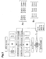
- Fig. 3 is a diagram showing a flow chart of the system which performs a high-fidelity color reproduction of the display color according to the above-mentioned system.
- a color C(X C , Y C , Z C ) signal is converted into the RGB display system using the X, Y and Z of each of the three primary colors at the maximum gradation value (2 n - 1) of the display device to determine the value in the RGB display system at the time.
- the values of corresponding (Xrd, Yrd, Zrd), (Xgd, Ygd, Zgd) and (Xbd, Ybd, Zbd) are determined, which in turn are used to calculate X C , Y C and Z C from equation (6).
- the above-mentioned calculation is repeated until a, b and c result in predefined values which are close to 1.
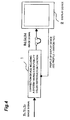
- Fig. 4 is a schematic diagram of an image display showing the block structure of the display device, which receives an image signal having display values X C , Y C and Z C , and after passing the signal through the system comprising the above-mentioned high-fidelity color reproduction function, displays the image signal having display values R d , G d and B d .
- numeral 1 denotes a correction device including a system comprising a high-fidelity color reproduction function
- numeral 2 denotes a display device.
- the correction device 1 includes a system comprising a high-fidelity color reproduction function which, when an image signal of the XYZ display system is input to the correction device 1, accurately converts the input gradation values of the XYZ colorimetric system to the RGB colorimetric system, and outputs the image signal of the RGB colorimetric system.
- the display device 2 receives the image signal of the RGB colorimetric system which is output from the correction device 1 and displays the image.
- the color display system of the present invention can be adapted to display devices of any form, it is suitable for applying not only to CRT's but also to LCD's and PDP's.
- a color display system for a display device according to the present invention can be used with various types of display devices. Therefore it can be widely used in a field where high-fidelity color reproduction is required for each of various types of display devices.
Landscapes
- Engineering & Computer Science (AREA)
- Multimedia (AREA)
- Signal Processing (AREA)
- General Physics & Mathematics (AREA)
- Biomedical Technology (AREA)
- General Health & Medical Sciences (AREA)
- Physics & Mathematics (AREA)
- Computer Hardware Design (AREA)
- Health & Medical Sciences (AREA)
- Theoretical Computer Science (AREA)
- Control Of Indicators Other Than Cathode Ray Tubes (AREA)
- Processing Of Color Television Signals (AREA)
- Controls And Circuits For Display Device (AREA)
- Liquid Crystal Display Device Control (AREA)
- Control Of Gas Discharge Display Tubes (AREA)
- Facsimile Image Signal Circuits (AREA)
Claims (2)
- Ein Farbanzeigesystem, das Folgendes beinhaltet:eine Korrekturvorrichtung (1) zum Empfangen eines Eingangsbildsignals in einem XYZkolorimetrischen System, das Eingangs-XYZ-Tristimuluswerte umfasst, zum akkuraten Umwandeln der Eingangs-XYZ-Tristimuluswerte in Vorrichtungs-RGB-Tristimuluswerte und zum Ausgeben eines Ausgangsbildsignals in einem RGB-kolorimetrischen System, das die Vorrichtungs-RGB-Tristimuluswerte umfasst, so dass ein Verfälschungsfehler aufgrund einer Nichtlinearität oder dergleichen von RGB-Primärfarben minimiert wird; undeine Anzeigevorrichtung (2) mit RGB-Primärfarben, von denen jede eine Farbart aufweist, die auf der Basis eines digitalen Anregungsniveaus variiert, wobei die Anzeigevorrichtung zum Anzeigen des Ausgangsbildsignals dient;wobei die Korrekturvorrichtung Folgendes beinhaltet:ein Mittel zum Umwandeln der Eingangs-XYZ-Tristimuluswerte XC, YC, ZC, die eine Farbe C in dem Eingangsbildsignal darstellen, wobei jeder der XYZ-Tristimuluswerte einen beliebigen ganzzahligen Stimuluswert zwischen 0 und {2n - 1} annehmen kann, wobei n eine Anzahl Bit der Daten ist, die das digitale Anregungsniveau darstellt, zu linearen RGB-Tristimuluswerten unter Verwendung eines XYZ-Tristimuluswertes, der dem jeweiligen maximalen Stimuluswert jeder der RGB-Primärfarben entspricht, ein Berechnungsmittel zum:(a) Bestimmen von für die bestimmte Anzeigevorrichtung des Systems intrinsischen Vorrichtungs-RGB-Tristimuluswerten (Rd, Gd und Bd), die den linearen RGB-Tristimuluswerten an einem Betriebspunkt d der Anzeigevorrichtung entsprechen, aus Messwerten eines zuvor gemessenen Halbton-Reproduktionsmerkmals der Anzeigevorrichtung,(b) Bestimmen von drei Sätzen Tristimuluswerten Xrd, Yrd, Zrd, Xgd, Ygd, Zgd, Xbd, Ybd, Zbd für jede der drei RGB-Primärfarben beim Anzeigen der Farbe C aus den Messwerten, und(c) Berechnen der Koeffizienten a, b und c aus


 ein Bestimmungsmittel zum Bestimmen, ob die in dem Berechnungsmittel gefundenen Koeffizienten a, b und c alle innerhalb eines vordefinierten Toleranzbereichs liegen, so dass die Koeffizienten a, b und c alle Werte aufweisen, die nahe bei 1 sind, oder nicht, und, wenn innerhalb des Toleranzbereichs, zum Ausgeben der Vorrichtungs-RGB-Tristimuluswerte (Rd, Gd und Bd) als die korrekten Werte, die dem Eingangsbildsignal entsprechen; undein Rückkopplungsmittel zum Rückkoppeln der Koeffizienten a, b und c, wenn von dem Bestimmungsmittel als außerhalb des Toleranzbereichs liegend bestimmt, an das Berechnungsmittel und Veranlassen, dass das Berechnungsmittel die Berechnung unter Verwendung der Koeffizienten a, b und c als korrigierter linearer RGB-Tristimuluswerte anstelle der vorherigen linearen RGB-Tristimuluswerte des Bestimmungsschritts (a) erneut durchführt.
 - Farbanzeigesystem für eine Anzeigevorrichtung gemäß Anspruch 1, wobei die Anzeigevorrichtung ein CRT, ein LCD oder ein PDP ist.
Applications Claiming Priority (2)
| Application Number | Priority Date | Filing Date | Title |
|---|---|---|---|
| JP2003427660 | 2003-12-24 | ||
| PCT/JP2004/019312 WO2005062628A1 (ja) | 2003-12-24 | 2004-12-24 | 表示デバイスの色表示方式 |
Publications (3)
| Publication Number | Publication Date |
|---|---|
| EP1701554A1 EP1701554A1 (de) | 2006-09-13 |
| EP1701554A4 EP1701554A4 (de) | 2010-03-03 |
| EP1701554B1 true EP1701554B1 (de) | 2013-06-19 |
Family
ID=34708904
Family Applications (1)
| Application Number | Title | Priority Date | Filing Date |
|---|---|---|---|
| EP04807669.9A Expired - Fee Related EP1701554B1 (de) | 2003-12-24 | 2004-12-24 | Farbanzeigesystem mit akkurater Umwandlung zwischen den RGB und XYZ kolorimetrischen Systemen |
Country Status (4)
| Country | Link |
|---|---|
| US (1) | US7453610B2 (de) |
| EP (1) | EP1701554B1 (de) |
| JP (1) | JP4122381B2 (de) |
| WO (1) | WO2005062628A1 (de) |
Families Citing this family (3)
| Publication number | Priority date | Publication date | Assignee | Title |
|---|---|---|---|---|
| TWI408670B (zh) * | 2010-03-17 | 2013-09-11 | 冠捷投資有限公司 | 用於顯示器色彩校正的查找表產生方法 |
| KR20130066129A (ko) * | 2011-12-12 | 2013-06-20 | 삼성디스플레이 주식회사 | 백라이트 유닛 및 이의 구동 방법 |
| EP2955711B1 (de) | 2014-05-09 | 2018-11-21 | Ams Ag | Verfahren zur Kalibrierung einer Farbraumtransformation, Verfahren zur Farbraumtransformation und Farbkontrollsystem |
Family Cites Families (6)
| Publication number | Priority date | Publication date | Assignee | Title |
|---|---|---|---|---|
| CN1153444C (zh) * | 1995-10-02 | 2004-06-09 | 佳能株式会社 | 图象处理装置及方法 |
| JPH0998444A (ja) * | 1995-10-02 | 1997-04-08 | Canon Inc | 画像処理方法および装置 |
| KR100363250B1 (ko) * | 1995-12-30 | 2003-03-15 | 삼성전자 주식회사 | 2차원색도분할을이용한색처리방법및장치 |
| JPH11112819A (ja) * | 1997-09-30 | 1999-04-23 | Fuji Photo Film Co Ltd | 色変換ルックアップテーブル並びにその作成方法および装置並びにそれを用いた画像の色変換方法および装置 |
| US6677958B2 (en) * | 2001-06-22 | 2004-01-13 | Eastman Kodak Company | Method for calibrating, characterizing and driving a color flat panel display |
| JP2003323610A (ja) * | 2002-03-01 | 2003-11-14 | Nec Corp | プロジェクタの色補正方法および色補正装置 |
-
2004
- 2004-12-24 EP EP04807669.9A patent/EP1701554B1/de not_active Expired - Fee Related
- 2004-12-24 JP JP2005516521A patent/JP4122381B2/ja not_active Expired - Lifetime
- 2004-12-24 WO PCT/JP2004/019312 patent/WO2005062628A1/ja not_active Ceased
-
2006
- 2006-06-22 US US11/472,604 patent/US7453610B2/en not_active Expired - Lifetime
Non-Patent Citations (1)
| Title |
|---|
| DAWN WALLNER: "Building ICC Profiles - the Mechanics and Engineering", 1 April 2000 (2000-04-01), XP055032635, Retrieved from the Internet <URL:http://www.color.org/icc-book1.pdf> [retrieved on 20120712] * |
Also Published As
| Publication number | Publication date |
|---|---|
| EP1701554A4 (de) | 2010-03-03 |
| US20060268301A1 (en) | 2006-11-30 |
| JPWO2005062628A1 (ja) | 2007-12-13 |
| EP1701554A1 (de) | 2006-09-13 |
| WO2005062628A1 (ja) | 2005-07-07 |
| US7453610B2 (en) | 2008-11-18 |
| JP4122381B2 (ja) | 2008-07-23 |
Similar Documents
| Publication | Publication Date | Title |
|---|---|---|
| KR100787215B1 (ko) | 표시 특성 교정 방법, 표시 특성 교정 장치 및 컴퓨터 프로그램이 기록된 기록매체 | |
| EP1271465B1 (de) | Verfahren zur Kalibrierung, Charakterisierung und Steuerung einer Anzeigetafel | |
| US5561459A (en) | Automatic profile generation for a self-calibrating color display | |
| KR101367199B1 (ko) | 영상표시장치 및 그의 디스플레이 특성 보정 방법 | |
| CN101521001B (zh) | 显示装置的色彩校正方法及装置 | |
| US8098932B2 (en) | Color correction method and apparatus of display apparatus | |
| US7075552B2 (en) | System and method for display grid characterization, calibration, and verification | |
| US20090128578A1 (en) | Methods and Systems for Efficient White Balance and Gamma Control | |
| JPH05127620A (ja) | 液晶投写型カラーデイスプレイの調整方法および調整回路 | |
| US20060071940A1 (en) | Correction data setting method and manufacturing method of image display apparatus | |
| US20100309218A1 (en) | Method for color calibration and device using the same | |
| US7561167B2 (en) | Image processing apparatus and image processing method | |
| JP4530200B2 (ja) | カラーモニタのキャリブレーション及び/またはプロファイル作成の方法及び装置 | |
| EP1701554A1 (de) | Farbanzeigesystem einer anzeigeeinrichtung | |
| CN103426393B (zh) | 显示设备色彩校正方法 | |
| JP5322326B2 (ja) | 色補正テーブル算出回路、色補正装置、表示装置、色補正方法、及びプログラム | |
| KR100565266B1 (ko) | 엘시디의 구간별 색온도 감마 보정방법 | |
| KR20110048508A (ko) | 필터를 이용한 디스플레이 특징화 | |
| JP2005249596A (ja) | 複数のカラーモニタのキャリブレーション方法 | |
| JPWO2007083717A1 (ja) | 色変換マトリクス作成方法及び色変換方法 | |
| Thomas et al. | Additivity based LC display color characterization | |
| JP5748236B2 (ja) | 色補正情報の生成方法、及び色補正装置 | |
| KR20080112598A (ko) | 선호색 검출 방법 및 장치와, 그를 이용한 액정 표시 장치 | |
| JPH10117289A (ja) | カラー画像形成システム及びその色合わせ方法 | |
| JP2005123840A (ja) | カラー画像処理装置及び方法 |
Legal Events
| Date | Code | Title | Description |
|---|---|---|---|
| PUAI | Public reference made under article 153(3) epc to a published international application that has entered the european phase |
Free format text: ORIGINAL CODE: 0009012 |
|
| 17P | Request for examination filed |
Effective date: 20060705 |
|
| AK | Designated contracting states |
Kind code of ref document: A1 Designated state(s): BE NL |
|
| DAX | Request for extension of the european patent (deleted) | ||
| RBV | Designated contracting states (corrected) |
Designated state(s): BE NL |
|
| RBV | Designated contracting states (corrected) |
Designated state(s): BE NL |
|
| A4 | Supplementary search report drawn up and despatched |
Effective date: 20100201 |
|
| 17Q | First examination report despatched |
Effective date: 20100528 |
|
| GRAP | Despatch of communication of intention to grant a patent |
Free format text: ORIGINAL CODE: EPIDOSNIGR1 |
|
| RIC1 | Information provided on ipc code assigned before grant |
Ipc: G09G 5/02 20060101ALN20121217BHEP Ipc: H04N 9/64 20060101AFI20121217BHEP |
|
| GRAS | Grant fee paid |
Free format text: ORIGINAL CODE: EPIDOSNIGR3 |
|
| GRAA | (expected) grant |
Free format text: ORIGINAL CODE: 0009210 |
|
| RAP1 | Party data changed (applicant data changed or rights of an application transferred) |
Owner name: NATIONAL UNIVERSITY CORPORATION SHIZUOKA UNIVERSIT |
|
| AK | Designated contracting states |
Kind code of ref document: B1 Designated state(s): BE NL |
|
| REG | Reference to a national code |
Ref country code: NL Ref legal event code: T3 |
|
| PGFP | Annual fee paid to national office [announced via postgrant information from national office to epo] |
Ref country code: NL Payment date: 20131031 Year of fee payment: 10 |
|
| PLBE | No opposition filed within time limit |
Free format text: ORIGINAL CODE: 0009261 |
|
| STAA | Information on the status of an ep patent application or granted ep patent |
Free format text: STATUS: NO OPPOSITION FILED WITHIN TIME LIMIT |
|
| 26N | No opposition filed |
Effective date: 20140320 |
|
| REG | Reference to a national code |
Ref country code: NL Ref legal event code: V1 Effective date: 20150701 |
|
| REG | Reference to a national code |
Ref country code: NL Ref legal event code: V1 Effective date: 20150701 |
|
| PG25 | Lapsed in a contracting state [announced via postgrant information from national office to epo] |
Ref country code: NL Free format text: LAPSE BECAUSE OF NON-PAYMENT OF DUE FEES Effective date: 20150701 |
|
| PGFP | Annual fee paid to national office [announced via postgrant information from national office to epo] |
Ref country code: BE Payment date: 20201222 Year of fee payment: 17 |
|
| REG | Reference to a national code |
Ref country code: BE Ref legal event code: MM Effective date: 20211231 |
|
| PG25 | Lapsed in a contracting state [announced via postgrant information from national office to epo] |
Ref country code: BE Free format text: LAPSE BECAUSE OF NON-PAYMENT OF DUE FEES Effective date: 20211231 |