EP1701420A1 - Répartiteur électrique et poste moyenne tension avec ce répartiteur - Google Patents
Répartiteur électrique et poste moyenne tension avec ce répartiteur Download PDFInfo
- Publication number
- EP1701420A1 EP1701420A1 EP05075547A EP05075547A EP1701420A1 EP 1701420 A1 EP1701420 A1 EP 1701420A1 EP 05075547 A EP05075547 A EP 05075547A EP 05075547 A EP05075547 A EP 05075547A EP 1701420 A1 EP1701420 A1 EP 1701420A1
- Authority
- EP
- European Patent Office
- Prior art keywords
- switchboard
- compartment
- electric
- enclosure
- electric switchboard
- Prior art date
- Legal status (The legal status is an assumption and is not a legal conclusion. Google has not performed a legal analysis and makes no representation as to the accuracy of the status listed.)
- Granted
Links
Images


Classifications
-
- F—MECHANICAL ENGINEERING; LIGHTING; HEATING; WEAPONS; BLASTING
- F16—ENGINEERING ELEMENTS AND UNITS; GENERAL MEASURES FOR PRODUCING AND MAINTAINING EFFECTIVE FUNCTIONING OF MACHINES OR INSTALLATIONS; THERMAL INSULATION IN GENERAL
- F16K—VALVES; TAPS; COCKS; ACTUATING-FLOATS; DEVICES FOR VENTING OR AERATING
- F16K3/00—Gate valves or sliding valves, i.e. cut-off apparatus with closing members having a sliding movement along the seat for opening and closing
- F16K3/22—Gate valves or sliding valves, i.e. cut-off apparatus with closing members having a sliding movement along the seat for opening and closing with sealing faces shaped as surfaces of solids of revolution
- F16K3/24—Gate valves or sliding valves, i.e. cut-off apparatus with closing members having a sliding movement along the seat for opening and closing with sealing faces shaped as surfaces of solids of revolution with cylindrical valve members
-
- H—ELECTRICITY
- H02—GENERATION; CONVERSION OR DISTRIBUTION OF ELECTRIC POWER
- H02B—BOARDS, SUBSTATIONS OR SWITCHING ARRANGEMENTS FOR THE SUPPLY OR DISTRIBUTION OF ELECTRIC POWER
- H02B1/00—Frameworks, boards, panels, desks, casings; Details of substations or switching arrangements
- H02B1/26—Casings; Parts thereof or accessories therefor
- H02B1/30—Cabinet-type casings; Parts thereof or accessories therefor
- H02B1/32—Mounting of devices therein
-
- F—MECHANICAL ENGINEERING; LIGHTING; HEATING; WEAPONS; BLASTING
- F16—ENGINEERING ELEMENTS AND UNITS; GENERAL MEASURES FOR PRODUCING AND MAINTAINING EFFECTIVE FUNCTIONING OF MACHINES OR INSTALLATIONS; THERMAL INSULATION IN GENERAL
- F16K—VALVES; TAPS; COCKS; ACTUATING-FLOATS; DEVICES FOR VENTING OR AERATING
- F16K27/00—Construction of housing; Use of materials therefor
- F16K27/04—Construction of housing; Use of materials therefor of sliding valves
-
- F—MECHANICAL ENGINEERING; LIGHTING; HEATING; WEAPONS; BLASTING
- F16—ENGINEERING ELEMENTS AND UNITS; GENERAL MEASURES FOR PRODUCING AND MAINTAINING EFFECTIVE FUNCTIONING OF MACHINES OR INSTALLATIONS; THERMAL INSULATION IN GENERAL
- F16K—VALVES; TAPS; COCKS; ACTUATING-FLOATS; DEVICES FOR VENTING OR AERATING
- F16K3/00—Gate valves or sliding valves, i.e. cut-off apparatus with closing members having a sliding movement along the seat for opening and closing
- F16K3/30—Details
- F16K3/314—Forms or constructions of slides; Attachment of the slide to the spindle
-
- H—ELECTRICITY
- H02—GENERATION; CONVERSION OR DISTRIBUTION OF ELECTRIC POWER
- H02B—BOARDS, SUBSTATIONS OR SWITCHING ARRANGEMENTS FOR THE SUPPLY OR DISTRIBUTION OF ELECTRIC POWER
- H02B1/00—Frameworks, boards, panels, desks, casings; Details of substations or switching arrangements
- H02B1/20—Bus-bar or other wiring layouts, e.g. in cubicles, in switchyards
-
- H—ELECTRICITY
- H02—GENERATION; CONVERSION OR DISTRIBUTION OF ELECTRIC POWER
- H02B—BOARDS, SUBSTATIONS OR SWITCHING ARRANGEMENTS FOR THE SUPPLY OR DISTRIBUTION OF ELECTRIC POWER
- H02B13/00—Arrangement of switchgear in which switches are enclosed in, or structurally associated with, a casing, e.g. cubicle
- H02B13/005—Electrical connection between switchgear cells
Definitions
- the present invention relates to an electric switchboard, and to a medium voltage substation comprising one or more of such switchboards, having improved functions and characteristics.
- a “medium voltage substation” it is here meant a substation for applications having a nominal rated voltage comprised between 1 kV and 70 kV.
- substations consist of electrical apparatuses widely used for distribution of electrical power; in particular, one basic task of a medium-voltage substation is to switch down, in a safe and reliable way, the voltage of distributed power to suitable levels which are useful for a wide type of users, such as utility companies, various type of plants, e.g. steel works, petrochemical plants, et cetera.
- each switchboard comprises a metallic enclosure, having usually a parallelepiped structure, inside which an adequate space is delimited for accommodating the various equipments which are necessary for performing the required system management functions that have to be dealt with for electrical energy distribution.
- these functions are usually divided into two different categories, generally indicated as primary functions and secondary functions; primary functions are those functions related to the main voltage, current and power distribution, while secondary functions are the ones related to auxiliary and control features.
- Some examples of primary functions are: making, breaking, conduct the nominal current, withstand the short circuit current for a certain time, disconnection, earthing, isolation of live parts from operators.
- secondary functions are: protection, interlocking, local or remote supervision, local or remote control, automation, measure, metering, diagnostic, communication.
- circuit breakers circuit breakers, disconnectors, various types of measuring and electronic devices, protective relays, busbars, plugs, et cetera.
- one significant drawback resides in the fact that the various components of each switchboard are connected to each other by cabling; for example, it is necessary to connect auxiliary contacts to terminal blocks, installing and cabling measuring devices, cabling all inputs and outputs to protection and control units, cabling contact position sensors, e.g. for interlocks, to required terminal blocks or relays. Then, when realizing the substation, the functional units of the various switchboards have to be properly wired in order to realize the needed functional coordination and interdependence. Clearly, this results in an over amount of operations which are costly and time consuming; further, the unavoidable cabling and wiring lead to a cumbersome design inside each switchboard, and makes the substation as a whole much more complex.
- each substation has a layout which is purposely designed based on specific customized requirements and should be tested before installation; as a matter of fact, the substation has first to be assembled in-factory in the operative configuration and tested; then, it should be dismantled and shipped to the application site, where it is finally reassembled again.
- the substation has first to be assembled in-factory in the operative configuration and tested; then, it should be dismantled and shipped to the application site, where it is finally reassembled again.
- a considerable amount of engineering and commissioning operations are involved, thus negatively influencing the overall manufacturing cost of the substation.
- the main aim of the present invention is to provide an electric switchboard, and a related medium voltage substation comprising such a switchboard, which allow to overcome the above mentioned drawbacks and disadvantages, and in particular which can be realized through an optimized structure and in a simplified manner with respect to prior art solutions, while offering at the same time improved performances and characteristics.
- an electric switchboard comprising an enclosure having a door and a plurality of walls which all together delimit an inside volume suitable to accommodate internal components of the switchboard, characterized in that said switchboard comprises a compartment which is shaped to allow performing wireless communication of signals between at least one of said internal components and one further component.
- the switchboard 1 comprises an enclosure having one (or more) door 2 provided at the front face, and a plurality of walls, namely a base wall 3, a top wall 4, a rear wall 5, two side walls 6, which all together delimit an inside volume 7 suitable to accommodate internal components of the switchboard 1 itself;
- the internal components usually comprise either electric and/or electronic devices, such as one or more circuit breakers 8, current and/or measuring devices sensors 9, such as for example sensors or instrument transformers, intelligent electronic devices 10 e.g. for diagnostic, protection, monitoring, controlling, digital interfaces, et cetera.
- the switchboard 1 comprises a dedicated communication compartment 100 which is shaped to allow performing wireless communication of signals 50 between at least one of the internal components and one further component; the further component(s) can be external to the switchboard 1, for example, one (or more) component belonging to an other switchboard, a remote control unit, or even a further internal component of the same switchboard 1.
- the compartment 100 is positioned within the inside volume 7 and comprises a plurality of perimeter walls 101 which are configured so as to delimit an internal dedicated environment 102 where the propagation of the signals 50 is substantially confined; in particular, the perimeter walls 101 of the compartment 100 are configured so as the internal dedicated environment 102 is divided off from the remaining part of the inside volume 7, namely they delimit an internal sub-volume partitioned from the remaining part of the inside volume 7 where the propagation of the signals 50 is substantially conveyed and confined.
- Suitable transceiving means comprising an antenna 103, are operatively connected to and pass through at least one of the perimeter walls 101.
- the perimeter walls 101 of the compartment 100 preferably all, comprise an anti-interference shielding layer, e.g. a layer suitable to oppose possible signal interferences and/or disturbances which could affect the quality and reliability of the signals under transmission, such as electromagnetic noise generated by various sources, radio-interference signals, and the like; more preferably, the perimeter walls 101 comprise a layer of electrically conductive material at least partially surrounding the dedicated environment 102 and having good electromagnetic shielding properties. In this way the conductive layer performs a shielding function and facilitates the propagation of signals 50 inside the compartment 100.
- an anti-interference shielding layer e.g. a layer suitable to oppose possible signal interferences and/or disturbances which could affect the quality and reliability of the signals under transmission, such as electromagnetic noise generated by various sources, radio-interference signals, and the like
- the perimeter walls 101 comprise a layer of electrically conductive material at least partially surrounding the dedicated environment 102 and having good electromagnetic shielding properties. In this way the conductive layer performs a shielding function and facilitates the propagation of
- the compartment 100 has a tunnel-shaped configuration which extends transversely, in a substantially rectilinear way, between the two opposite side walls 6 of the enclosure which - in correspondence of the end portions of the compartment 100 - may exhibit suitable openings at one or both ends.
- the tunnel-shaped compartment 100 has a substantially rectangular cross-section, wherein the lengths of the sides (a,b) of the cross-section are in a ratio of 1:2; this solution allows improving the quality of the signals propagation in particular at high frequency e.g. in the range of GHz; for example, with a frequency of transmission of 5 GHz side (a) may have a length of 0,05 m, whereas side (b) has a length of 0,025 m.
- At least one signal absorbing element 11 e.g. a suitably shaped end-cap which is operatively coupled to the tunnel-shaped compartment 100 at an end portion thereof; preferably, the absorbing element 11 comprises a conductive foam, for example a foamed polyurethane doped with conductive particles of a type commercially available on the market.
- the compartment 100 is realized by using a metallic wave guide device illustrated in figure 2 also by the reference number 100; advantageously, the device 100 is made of a single body of aluminum, or alternatively of copper, of appropriate thickness.
- the perimeter walls 101 are constituted only by the selected conductive material which is used at the same time, as the partitioning elements, as the anti-interference shielding layer and also it allows the propagation of the signals inside the compartment itself.
- the metallic wave guide device 100 is placed within the inside volume 7 and is removably connected to the enclosure, for example by means of a drawer-like system, or according to a snap-fit coupling, or with other suitable mechanical couplings; in this way, maintenance interventions, replacements et cetera, are significantly eased.
- the device 100 can be fixedly attached to the enclosure, e.g. by using suitable fastening means.
- the compartment 100 could be positioned outside the switchboard 1 and operatively coupled to its enclosure.
- the switchboard 1 according to the invention can be advantageously used in medium as well as low voltage voltage applications and it is particularly suitable for realizing a medium voltage substation; hence, a further object of the present invention relates to a medium voltage substation comprising at least one switchboard 1 of the type above described.
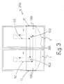
- the substation 200 preferably comprises at least two switchboards 1 which are positioned adjacent with their respective compartments 100 facing to and slightly displaced from each other.
- the switchboards 1 are positioned side by side to each other with their respective compartments 100 operatively linked so as to define a segmented substantially rectilinear tunnel 300, which in practice constitutes a wireless communication path inside which the signals travel.
- a segmented substantially rectilinear tunnel 300 which in practice constitutes a wireless communication path inside which the signals travel.
- there are provided two corresponding signal absorbing elements 11 which are connected each to a respective end portion of a compartment 100.
- the substation 200 can be clearly composed by a desired number of switchboards 1 which can be placed side by side, preferably in a row.
- the substation 200 comprises a plurality of switchboards 1 each having a corresponding enclosure provided with a least a door 2 and a plurality of walls which all together delimit an inside volume 7 suitable to accommodate internal components; each switchboard 1 comprises an own compartment 100 which is positioned within the respective inside volume 7 and is shaped to allow performing wireless communication of signals; the compartments 100 are positioned so as to define a segmented substantially rectilinear wireless communication path 300 extending through the plurality of inside volumes 7 defined by the switchboards 1.
- two absorbing elements 11 are preferably positioned at the two opposite external ends of the realized segmented path 300.
- the signals 50 coming from a component of a first switchboard 1, preferably in the form of radio frequency waves properly modulated in order to carry the desired data, are transmitted into the dedicated environment 102 by the antenna of the transceiving means 103; there, they are confined inside the path 300 defined by the various compartments 100 and conveyed, in this protected and shielded room, towards the antenna 103 associated to an other compartment 100; in turn, this antenna allows transmitting the signals 50 to the component of a second switchboard 1 devised to receive them.
- the elements 11 at the end of the path 300 avoid or at least substantially reduce the risk of signal reflection.
- the switchboard according to the present invention and the related medium voltage substation as well fully achieves the intended aim, giving several advantages with respect to prior art solutions.
- the solution conceived thanks to the fact that allows transmitting signals in a wireless manner and in a protected environment purposely and exclusively dedicated to communication results in a substantial simplification of the constructive layout of each switchboard, and moreover of the whole layout of substations which are composed by modules functionally interdependent but structurally/mechanically independent.
- the switchboards have to be simply placed close one to the other without any cabling or electrical/mechanical continuity therebetween, but just facing the compartments 100 to each other; as a matter of fact, manufacturing, commissioning and maintenance operations are extremely simplified, since for example in-factory assembling for tests and on-site final installations do not require any assembling-dismantling- and reassembling operations which are instead mandatory for prior art solutions.
- manufacturing, commissioning and maintenance operations are extremely simplified, since for example in-factory assembling for tests and on-site final installations do not require any assembling-dismantling- and reassembling operations which are instead mandatory for prior art solutions.
- it is possible to vary the layout of the substation by adding/eliminating/substituting one or more switchboards, in a very simple and fast way.
- the signals are transmitted in a reliable and protected way, with the possibility of data communication practically at any desired speed, be it high or low, and at the desired single frequency or even by multiple frequencies; for example, it is possible the transfer of real-time process data, such as analog and voltage samples. It is also to be underlined that such results are achieved by an innovative solution which is structurally simple and can be realized by means of extremely simplified manufacturing operations, thus obtaining significant savings in terms of material, time and production costs; in particular, when the compartment 100 is placed inside the enclosure, it constitutes in practice a further component of the switchboard and is directly and automatically protected from the environment external to the switchboard 1 itself.
- the switchboard and the related medium voltage substation are susceptible of modifications and variations, all of which are within the scope of the inventive concept; all the details may furthermore be replaced with technically equivalent elements.
- the compartment 100 can be realized by using separate pieces, e.g. a plurality of sheets of suitable materials which could be connected to the enclosure piece by piece or first joined to each other and then as a whole to the enclosure, or even a tube of plastics coated by a layer of electrically conductive material; the shape of the compartment 100 could be also different, or the perimeter walls 101 can be realized combining more layers of different type and material.
- interconnecting elements e.g.
Priority Applications (9)
| Application Number | Priority Date | Filing Date | Title |
|---|---|---|---|
| EP05075547.9A EP1701420B1 (fr) | 2005-03-07 | 2005-03-07 | Répartiteur électrique et poste moyenne tension avec ce répartiteur |
| ZA200601116A ZA200601116B (en) | 2005-03-07 | 2006-02-08 | An electric switchboard, and a medium voltage substation comprising such a switchboard |
| RU2006104969/07A RU2426210C2 (ru) | 2005-03-07 | 2006-02-14 | Электрический распределительный щит и подстанция среднего напряжения, содержащая распределительный щит |
| JP2006047012A JP4933109B2 (ja) | 2005-03-07 | 2006-02-23 | エレクトリック・スイッチボード、及びそのようなスイッチボードを有する中電圧用変電所 |
| CN200610058623XA CN1832281B (zh) | 2005-03-07 | 2006-03-02 | 一种电气配电盘以及包括此种配电盘的中压分站 |
| UAA200602475A UA91001C2 (uk) | 2005-03-07 | 2006-03-06 | Електричний розподільний щит та підстанція з середніми значеннями напруги, яка містить такий розподільний щит (варіанти) |
| BRPI0600788-0A BRPI0600788A (pt) | 2005-03-07 | 2006-03-06 | quadro de distribuição elétrico, e subestação de média voltagem compreendendo tal quadro de distribuição |
| KR1020060021136A KR101276972B1 (ko) | 2005-03-07 | 2006-03-07 | 전기 스위치보드 및 이를 포함하는 중간 전압 서브스테이션 |
| US11/368,413 US20060198085A1 (en) | 2005-03-07 | 2006-03-07 | Electric switchboard, and a medium voltage substation comprising such a switchboard |
Applications Claiming Priority (1)
| Application Number | Priority Date | Filing Date | Title |
|---|---|---|---|
| EP05075547.9A EP1701420B1 (fr) | 2005-03-07 | 2005-03-07 | Répartiteur électrique et poste moyenne tension avec ce répartiteur |
Publications (2)
| Publication Number | Publication Date |
|---|---|
| EP1701420A1 true EP1701420A1 (fr) | 2006-09-13 |
| EP1701420B1 EP1701420B1 (fr) | 2014-04-30 |
Family
ID=34938085
Family Applications (1)
| Application Number | Title | Priority Date | Filing Date |
|---|---|---|---|
| EP05075547.9A Not-in-force EP1701420B1 (fr) | 2005-03-07 | 2005-03-07 | Répartiteur électrique et poste moyenne tension avec ce répartiteur |
Country Status (9)
| Country | Link |
|---|---|
| US (1) | US20060198085A1 (fr) |
| EP (1) | EP1701420B1 (fr) |
| JP (1) | JP4933109B2 (fr) |
| KR (1) | KR101276972B1 (fr) |
| CN (1) | CN1832281B (fr) |
| BR (1) | BRPI0600788A (fr) |
| RU (1) | RU2426210C2 (fr) |
| UA (1) | UA91001C2 (fr) |
| ZA (1) | ZA200601116B (fr) |
Cited By (3)
| Publication number | Priority date | Publication date | Assignee | Title |
|---|---|---|---|---|
| EP2093915A1 (fr) | 2008-02-19 | 2009-08-26 | Abb Research Ltd. | Synchronisation horaire dans un réseau |
| DE102015104922A1 (de) * | 2015-03-31 | 2016-10-06 | Eaton Industries (Austria) Gmbh | Schaltschrank mit verbesserter Funkübertragung zwischen Messsensoren und einer Basisstation |
| EP3145024A1 (fr) * | 2015-09-17 | 2017-03-22 | Berthold Sichert GmbH | Module d'antennes de toit, complement d'equipement d'antennes pour armoires de distribution et systeme modulaire destine a la fabrication des armoires de distribution |
Families Citing this family (2)
| Publication number | Priority date | Publication date | Assignee | Title |
|---|---|---|---|---|
| EP3382793A1 (fr) * | 2017-03-31 | 2018-10-03 | Antennentechnik ABB Bad Blankenburg GmbH | Dispositif électrotechnique |
| DE102019102386A1 (de) * | 2018-05-23 | 2019-11-28 | Antennentechnik Bad Blankenburg Gmbh | Elektrotechnische Einrichtung sowie Abdeckung für einen Wartungszugang einer derartigen Einrichtung |
Citations (4)
| Publication number | Priority date | Publication date | Assignee | Title |
|---|---|---|---|---|
| GB1102698A (en) * | 1964-04-13 | 1968-02-07 | Hazemeijer Co | Apparatus for the production of a conductive connection between electric appliances |
| US5025171A (en) * | 1989-09-22 | 1991-06-18 | S&C Electric Company | Method and arrangement for providing power operation of switchgear apparatus |
| US6366448B1 (en) | 1999-06-22 | 2002-04-02 | Agilent Technologies, Inc. | High-voltage supply including first and second segments respectively including only low voltage components and low and high-voltage components |
| US20040253922A1 (en) * | 2003-06-11 | 2004-12-16 | Deblanc James J. | Data-storage system having a wireless connection architecture for wireless data exchange between modules |
Family Cites Families (10)
| Publication number | Priority date | Publication date | Assignee | Title |
|---|---|---|---|---|
| AU3060977A (en) * | 1976-12-14 | 1979-05-24 | Tokyo Shibaura Electric Co | Enclosure for electrical apparatus |
| US4661998A (en) * | 1983-09-22 | 1987-04-28 | Matsushita Electric Industrial Co. Ltd. | Double superheterodyne tuner |
| JPS61112503A (ja) * | 1984-11-06 | 1986-05-30 | 株式会社東芝 | 閉鎖配電盤 |
| US4742428A (en) * | 1987-06-23 | 1988-05-03 | Bbc Brown Boveri Inc. | Protective relay and drawout case therefor |
| DE4102019C1 (fr) * | 1991-01-24 | 1992-07-09 | Schroff Gmbh, 7541 Straubenhardt, De | |
| JP3240833B2 (ja) * | 1994-06-07 | 2001-12-25 | 三菱電機株式会社 | 閉鎖配電盤の閉鎖箱及びそれを用いた閉鎖配電盤の組立方法 |
| US5424911A (en) * | 1994-08-24 | 1995-06-13 | General Electric Company | Compact motor controller assembly |
| JP3434758B2 (ja) * | 1999-12-14 | 2003-08-11 | 寺崎電気産業株式会社 | 配電盤 |
| DE10137746C1 (de) * | 2001-08-01 | 2002-10-10 | Schroff Gmbh | Frontteil für elektronische Steckbaugruppen |
| DE10149445C1 (de) * | 2001-10-08 | 2002-10-10 | Schroff Gmbh | HF-geschirmter Baugruppenträger |
-
2005
- 2005-03-07 EP EP05075547.9A patent/EP1701420B1/fr not_active Not-in-force
-
2006
- 2006-02-08 ZA ZA200601116A patent/ZA200601116B/xx unknown
- 2006-02-14 RU RU2006104969/07A patent/RU2426210C2/ru not_active IP Right Cessation
- 2006-02-23 JP JP2006047012A patent/JP4933109B2/ja not_active Expired - Fee Related
- 2006-03-02 CN CN200610058623XA patent/CN1832281B/zh not_active Expired - Fee Related
- 2006-03-06 UA UAA200602475A patent/UA91001C2/uk unknown
- 2006-03-06 BR BRPI0600788-0A patent/BRPI0600788A/pt not_active Application Discontinuation
- 2006-03-07 KR KR1020060021136A patent/KR101276972B1/ko not_active IP Right Cessation
- 2006-03-07 US US11/368,413 patent/US20060198085A1/en not_active Abandoned
Patent Citations (4)
| Publication number | Priority date | Publication date | Assignee | Title |
|---|---|---|---|---|
| GB1102698A (en) * | 1964-04-13 | 1968-02-07 | Hazemeijer Co | Apparatus for the production of a conductive connection between electric appliances |
| US5025171A (en) * | 1989-09-22 | 1991-06-18 | S&C Electric Company | Method and arrangement for providing power operation of switchgear apparatus |
| US6366448B1 (en) | 1999-06-22 | 2002-04-02 | Agilent Technologies, Inc. | High-voltage supply including first and second segments respectively including only low voltage components and low and high-voltage components |
| US20040253922A1 (en) * | 2003-06-11 | 2004-12-16 | Deblanc James J. | Data-storage system having a wireless connection architecture for wireless data exchange between modules |
Cited By (3)
| Publication number | Priority date | Publication date | Assignee | Title |
|---|---|---|---|---|
| EP2093915A1 (fr) | 2008-02-19 | 2009-08-26 | Abb Research Ltd. | Synchronisation horaire dans un réseau |
| DE102015104922A1 (de) * | 2015-03-31 | 2016-10-06 | Eaton Industries (Austria) Gmbh | Schaltschrank mit verbesserter Funkübertragung zwischen Messsensoren und einer Basisstation |
| EP3145024A1 (fr) * | 2015-09-17 | 2017-03-22 | Berthold Sichert GmbH | Module d'antennes de toit, complement d'equipement d'antennes pour armoires de distribution et systeme modulaire destine a la fabrication des armoires de distribution |
Also Published As
| Publication number | Publication date |
|---|---|
| UA91001C2 (uk) | 2010-06-25 |
| JP2006254686A (ja) | 2006-09-21 |
| EP1701420B1 (fr) | 2014-04-30 |
| CN1832281A (zh) | 2006-09-13 |
| ZA200601116B (en) | 2007-03-28 |
| US20060198085A1 (en) | 2006-09-07 |
| KR101276972B1 (ko) | 2013-06-19 |
| BRPI0600788A (pt) | 2006-11-07 |
| KR20060096917A (ko) | 2006-09-13 |
| RU2426210C2 (ru) | 2011-08-10 |
| CN1832281B (zh) | 2010-08-18 |
| JP4933109B2 (ja) | 2012-05-16 |
| RU2006104969A (ru) | 2007-09-27 |
Similar Documents
| Publication | Publication Date | Title |
|---|---|---|
| US8212635B2 (en) | Surface wave coupler | |
| US8269583B2 (en) | Using surface wave propagation to communicate an information-bearing signal through a barrier | |
| US6255935B1 (en) | Coupling capacitor having an integrated connecting cable | |
| EP1701420B1 (fr) | Répartiteur électrique et poste moyenne tension avec ce répartiteur | |
| US20110136432A1 (en) | Using an electric power cable as the vehicle for communicating an information-bearing signal through a barrier | |
| KR20120124020A (ko) | 전기 전력 스위치, 및 전력 스위치를 포함하는 제어 패널 | |
| JP4275365B2 (ja) | 複合形ガス絶縁開閉装置 | |
| WO1997028590A1 (fr) | Procede de determination de la position d'un appareil de commutation | |
| JPH0238524Y2 (fr) | ||
| RU2685237C2 (ru) | Электрический защитный прибор для среднего напряжения с измерением тока | |
| KR950003867B1 (ko) | 금속함체형 스위치기어 | |
| JPH0626444B2 (ja) | 小容量配電用変電塔 | |
| EP0878041A1 (fr) | Dispositif blinde | |
| EP1521381A1 (fr) | Systeme de couplage capacitif isole a moyenne tension | |
| CN112602242A (zh) | 多相开关设备 | |
| US4689717A (en) | Cast housing for medium-voltage switchgear | |
| EP2733808B1 (fr) | Procédé et système pour la suppression de transitoires très rapides | |
| EP3709332B1 (fr) | Appareillage de commutation isolé pour systèmes d'alimentation électrique | |
| CN210040949U (zh) | 高压开关柜 | |
| US11289792B2 (en) | Communication device comprising a mounting structure and valve unit | |
| EP4120477A1 (fr) | Module d'antenne pour la communication sans fil par ondes électromagnétiques à l'intérieur d'une armoire électrique, antenne à onde de fuite comprenant une pluralité de modules d'antenne et installation de commutation comprenant une telle antenne à onde de fuite | |
| KR102613611B1 (ko) | 내외장 듀얼부분방전센서가 부착된 모듈형 철도용 29㎸ 친환경 절연개폐장치 | |
| CN204947330U (zh) | 一种固定式高压出线柜 | |
| CN111525397A (zh) | 开关柜 | |
| KR20240011312A (ko) | 기준값을 이용한 이상징후 감시용 배전반 |
Legal Events
| Date | Code | Title | Description |
|---|---|---|---|
| PUAI | Public reference made under article 153(3) epc to a published international application that has entered the european phase |
Free format text: ORIGINAL CODE: 0009012 |
|
| AK | Designated contracting states |
Kind code of ref document: A1 Designated state(s): AT BE BG CH CY CZ DE DK EE ES FI FR GB GR HU IE IS IT LI LT LU MC NL PL PT RO SE SI SK TR |
|
| AX | Request for extension of the european patent |
Extension state: AL BA HR LV MK YU |
|
| 17P | Request for examination filed |
Effective date: 20070130 |
|
| AKX | Designation fees paid |
Designated state(s): AT BE BG CH CY CZ DE DK EE ES FI FR GB GR HU IE IS IT LI LT LU MC NL PL PT RO SE SI SK TR |
|
| 17Q | First examination report despatched |
Effective date: 20120508 |
|
| GRAP | Despatch of communication of intention to grant a patent |
Free format text: ORIGINAL CODE: EPIDOSNIGR1 |
|
| INTG | Intention to grant announced |
Effective date: 20131004 |
|
| RIN1 | Information on inventor provided before grant (corrected) |
Inventor name: TELLARINI, MARCO Inventor name: DECK, BERNHARD Inventor name: RUDOLPH, PAUL |
|
| GRAS | Grant fee paid |
Free format text: ORIGINAL CODE: EPIDOSNIGR3 |
|
| GRAA | (expected) grant |
Free format text: ORIGINAL CODE: 0009210 |
|
| AK | Designated contracting states |
Kind code of ref document: B1 Designated state(s): AT BE BG CH CY CZ DE DK EE ES FI FR GB GR HU IE IS IT LI LT LU MC NL PL PT RO SE SI SK TR |
|
| REG | Reference to a national code |
Ref country code: GB Ref legal event code: FG4D Ref country code: CH Ref legal event code: EP |
|
| REG | Reference to a national code |
Ref country code: DE Ref legal event code: R081 Ref document number: 602005043423 Country of ref document: DE Owner name: ABB SCHWEIZ AG, CH Free format text: FORMER OWNER: ABB TECHNOLOGY AG, ZUERICH, CH |
|
| REG | Reference to a national code |
Ref country code: AT Ref legal event code: REF Ref document number: 665671 Country of ref document: AT Kind code of ref document: T Effective date: 20140515 |
|
| REG | Reference to a national code |
Ref country code: IE Ref legal event code: FG4D |
|
| REG | Reference to a national code |
Ref country code: DE Ref legal event code: R096 Ref document number: 602005043423 Country of ref document: DE Effective date: 20140612 |
|
| REG | Reference to a national code |
Ref country code: SE Ref legal event code: TRGR |
|
| REG | Reference to a national code |
Ref country code: AT Ref legal event code: MK05 Ref document number: 665671 Country of ref document: AT Kind code of ref document: T Effective date: 20140430 |
|
| REG | Reference to a national code |
Ref country code: LT Ref legal event code: MG4D |
|
| REG | Reference to a national code |
Ref country code: NL Ref legal event code: VDEP Effective date: 20140430 |
|
| PG25 | Lapsed in a contracting state [announced via postgrant information from national office to epo] |
Ref country code: CY Free format text: LAPSE BECAUSE OF FAILURE TO SUBMIT A TRANSLATION OF THE DESCRIPTION OR TO PAY THE FEE WITHIN THE PRESCRIBED TIME-LIMIT Effective date: 20140430 Ref country code: GR Free format text: LAPSE BECAUSE OF FAILURE TO SUBMIT A TRANSLATION OF THE DESCRIPTION OR TO PAY THE FEE WITHIN THE PRESCRIBED TIME-LIMIT Effective date: 20140731 Ref country code: NL Free format text: LAPSE BECAUSE OF FAILURE TO SUBMIT A TRANSLATION OF THE DESCRIPTION OR TO PAY THE FEE WITHIN THE PRESCRIBED TIME-LIMIT Effective date: 20140430 Ref country code: IS Free format text: LAPSE BECAUSE OF FAILURE TO SUBMIT A TRANSLATION OF THE DESCRIPTION OR TO PAY THE FEE WITHIN THE PRESCRIBED TIME-LIMIT Effective date: 20140830 Ref country code: LT Free format text: LAPSE BECAUSE OF FAILURE TO SUBMIT A TRANSLATION OF THE DESCRIPTION OR TO PAY THE FEE WITHIN THE PRESCRIBED TIME-LIMIT Effective date: 20140430 Ref country code: BG Free format text: LAPSE BECAUSE OF FAILURE TO SUBMIT A TRANSLATION OF THE DESCRIPTION OR TO PAY THE FEE WITHIN THE PRESCRIBED TIME-LIMIT Effective date: 20140730 |
|
| PG25 | Lapsed in a contracting state [announced via postgrant information from national office to epo] |
Ref country code: AT Free format text: LAPSE BECAUSE OF FAILURE TO SUBMIT A TRANSLATION OF THE DESCRIPTION OR TO PAY THE FEE WITHIN THE PRESCRIBED TIME-LIMIT Effective date: 20140430 Ref country code: PL Free format text: LAPSE BECAUSE OF FAILURE TO SUBMIT A TRANSLATION OF THE DESCRIPTION OR TO PAY THE FEE WITHIN THE PRESCRIBED TIME-LIMIT Effective date: 20140430 Ref country code: ES Free format text: LAPSE BECAUSE OF FAILURE TO SUBMIT A TRANSLATION OF THE DESCRIPTION OR TO PAY THE FEE WITHIN THE PRESCRIBED TIME-LIMIT Effective date: 20140430 |
|
| PG25 | Lapsed in a contracting state [announced via postgrant information from national office to epo] |
Ref country code: PT Free format text: LAPSE BECAUSE OF FAILURE TO SUBMIT A TRANSLATION OF THE DESCRIPTION OR TO PAY THE FEE WITHIN THE PRESCRIBED TIME-LIMIT Effective date: 20140901 |
|
| PG25 | Lapsed in a contracting state [announced via postgrant information from national office to epo] |
Ref country code: BE Free format text: LAPSE BECAUSE OF FAILURE TO SUBMIT A TRANSLATION OF THE DESCRIPTION OR TO PAY THE FEE WITHIN THE PRESCRIBED TIME-LIMIT Effective date: 20140430 Ref country code: SK Free format text: LAPSE BECAUSE OF FAILURE TO SUBMIT A TRANSLATION OF THE DESCRIPTION OR TO PAY THE FEE WITHIN THE PRESCRIBED TIME-LIMIT Effective date: 20140430 Ref country code: CZ Free format text: LAPSE BECAUSE OF FAILURE TO SUBMIT A TRANSLATION OF THE DESCRIPTION OR TO PAY THE FEE WITHIN THE PRESCRIBED TIME-LIMIT Effective date: 20140430 Ref country code: DK Free format text: LAPSE BECAUSE OF FAILURE TO SUBMIT A TRANSLATION OF THE DESCRIPTION OR TO PAY THE FEE WITHIN THE PRESCRIBED TIME-LIMIT Effective date: 20140430 Ref country code: RO Free format text: LAPSE BECAUSE OF FAILURE TO SUBMIT A TRANSLATION OF THE DESCRIPTION OR TO PAY THE FEE WITHIN THE PRESCRIBED TIME-LIMIT Effective date: 20140430 Ref country code: EE Free format text: LAPSE BECAUSE OF FAILURE TO SUBMIT A TRANSLATION OF THE DESCRIPTION OR TO PAY THE FEE WITHIN THE PRESCRIBED TIME-LIMIT Effective date: 20140430 |
|
| REG | Reference to a national code |
Ref country code: DE Ref legal event code: R097 Ref document number: 602005043423 Country of ref document: DE |
|
| PLBE | No opposition filed within time limit |
Free format text: ORIGINAL CODE: 0009261 |
|
| STAA | Information on the status of an ep patent application or granted ep patent |
Free format text: STATUS: NO OPPOSITION FILED WITHIN TIME LIMIT |
|
| 26N | No opposition filed |
Effective date: 20150202 |
|
| REG | Reference to a national code |
Ref country code: DE Ref legal event code: R097 Ref document number: 602005043423 Country of ref document: DE Effective date: 20150202 |
|
| PG25 | Lapsed in a contracting state [announced via postgrant information from national office to epo] |
Ref country code: SI Free format text: LAPSE BECAUSE OF FAILURE TO SUBMIT A TRANSLATION OF THE DESCRIPTION OR TO PAY THE FEE WITHIN THE PRESCRIBED TIME-LIMIT Effective date: 20140430 |
|
| PG25 | Lapsed in a contracting state [announced via postgrant information from national office to epo] |
Ref country code: LU Free format text: LAPSE BECAUSE OF FAILURE TO SUBMIT A TRANSLATION OF THE DESCRIPTION OR TO PAY THE FEE WITHIN THE PRESCRIBED TIME-LIMIT Effective date: 20150307 Ref country code: MC Free format text: LAPSE BECAUSE OF FAILURE TO SUBMIT A TRANSLATION OF THE DESCRIPTION OR TO PAY THE FEE WITHIN THE PRESCRIBED TIME-LIMIT Effective date: 20140430 |
|
| REG | Reference to a national code |
Ref country code: CH Ref legal event code: PL |
|
| REG | Reference to a national code |
Ref country code: IE Ref legal event code: MM4A |
|
| PG25 | Lapsed in a contracting state [announced via postgrant information from national office to epo] |
Ref country code: IE Free format text: LAPSE BECAUSE OF NON-PAYMENT OF DUE FEES Effective date: 20150307 Ref country code: CH Free format text: LAPSE BECAUSE OF NON-PAYMENT OF DUE FEES Effective date: 20150331 Ref country code: LI Free format text: LAPSE BECAUSE OF NON-PAYMENT OF DUE FEES Effective date: 20150331 |
|
| REG | Reference to a national code |
Ref country code: FR Ref legal event code: PLFP Year of fee payment: 12 |
|
| PGFP | Annual fee paid to national office [announced via postgrant information from national office to epo] |
Ref country code: GB Payment date: 20160321 Year of fee payment: 12 Ref country code: SE Payment date: 20160321 Year of fee payment: 12 Ref country code: FI Payment date: 20160311 Year of fee payment: 12 Ref country code: FR Payment date: 20160321 Year of fee payment: 12 |
|
| PGFP | Annual fee paid to national office [announced via postgrant information from national office to epo] |
Ref country code: DE Payment date: 20160330 Year of fee payment: 12 |
|
| PGFP | Annual fee paid to national office [announced via postgrant information from national office to epo] |
Ref country code: IT Payment date: 20160324 Year of fee payment: 12 |
|
| REG | Reference to a national code |
Ref country code: DE Ref legal event code: R082 Ref document number: 602005043423 Country of ref document: DE Representative=s name: KUHNEN & WACKER PATENT- UND RECHTSANWALTSBUERO, DE Ref country code: DE Ref legal event code: R081 Ref document number: 602005043423 Country of ref document: DE Owner name: ABB SCHWEIZ AG, CH Free format text: FORMER OWNER: ABB TECHNOLOGY AG, ZUERICH, CH |
|
| PG25 | Lapsed in a contracting state [announced via postgrant information from national office to epo] |
Ref country code: HU Free format text: LAPSE BECAUSE OF FAILURE TO SUBMIT A TRANSLATION OF THE DESCRIPTION OR TO PAY THE FEE WITHIN THE PRESCRIBED TIME-LIMIT; INVALID AB INITIO Effective date: 20050307 |
|
| PG25 | Lapsed in a contracting state [announced via postgrant information from national office to epo] |
Ref country code: TR Free format text: LAPSE BECAUSE OF FAILURE TO SUBMIT A TRANSLATION OF THE DESCRIPTION OR TO PAY THE FEE WITHIN THE PRESCRIBED TIME-LIMIT Effective date: 20140430 |
|
| REG | Reference to a national code |
Ref country code: DE Ref legal event code: R119 Ref document number: 602005043423 Country of ref document: DE |
|
| PG25 | Lapsed in a contracting state [announced via postgrant information from national office to epo] |
Ref country code: FI Free format text: LAPSE BECAUSE OF NON-PAYMENT OF DUE FEES Effective date: 20170307 |
|
| REG | Reference to a national code |
Ref country code: SE Ref legal event code: EUG |
|
| GBPC | Gb: european patent ceased through non-payment of renewal fee |
Effective date: 20170307 |
|
| PG25 | Lapsed in a contracting state [announced via postgrant information from national office to epo] |
Ref country code: SE Free format text: LAPSE BECAUSE OF NON-PAYMENT OF DUE FEES Effective date: 20170308 |
|
| REG | Reference to a national code |
Ref country code: FR Ref legal event code: ST Effective date: 20171130 |
|
| PG25 | Lapsed in a contracting state [announced via postgrant information from national office to epo] |
Ref country code: DE Free format text: LAPSE BECAUSE OF NON-PAYMENT OF DUE FEES Effective date: 20171003 Ref country code: FR Free format text: LAPSE BECAUSE OF NON-PAYMENT OF DUE FEES Effective date: 20170331 |
|
| PG25 | Lapsed in a contracting state [announced via postgrant information from national office to epo] |
Ref country code: GB Free format text: LAPSE BECAUSE OF NON-PAYMENT OF DUE FEES Effective date: 20170307 Ref country code: IT Free format text: LAPSE BECAUSE OF NON-PAYMENT OF DUE FEES Effective date: 20170307 |