EP1701147A1 - Apparatus for producing pipes and method for corresponding fault detection - Google Patents
Apparatus for producing pipes and method for corresponding fault detection Download PDFInfo
- Publication number
- EP1701147A1 EP1701147A1 EP05005241A EP05005241A EP1701147A1 EP 1701147 A1 EP1701147 A1 EP 1701147A1 EP 05005241 A EP05005241 A EP 05005241A EP 05005241 A EP05005241 A EP 05005241A EP 1701147 A1 EP1701147 A1 EP 1701147A1
- Authority
- EP
- European Patent Office
- Prior art keywords
- pipe
- camera
- installation
- wall
- analysis
- Prior art date
- Legal status (The legal status is an assumption and is not a legal conclusion. Google has not performed a legal analysis and makes no representation as to the accuracy of the status listed.)
- Granted
Links
Images

Classifications
-
- B—PERFORMING OPERATIONS; TRANSPORTING
- B29—WORKING OF PLASTICS; WORKING OF SUBSTANCES IN A PLASTIC STATE IN GENERAL
- B29D—PRODUCING PARTICULAR ARTICLES FROM PLASTICS OR FROM SUBSTANCES IN A PLASTIC STATE
- B29D23/00—Producing tubular articles
- B29D23/001—Pipes; Pipe joints
-
- B—PERFORMING OPERATIONS; TRANSPORTING
- B29—WORKING OF PLASTICS; WORKING OF SUBSTANCES IN A PLASTIC STATE IN GENERAL
- B29C—SHAPING OR JOINING OF PLASTICS; SHAPING OF MATERIAL IN A PLASTIC STATE, NOT OTHERWISE PROVIDED FOR; AFTER-TREATMENT OF THE SHAPED PRODUCTS, e.g. REPAIRING
- B29C48/00—Extrusion moulding, i.e. expressing the moulding material through a die or nozzle which imparts the desired form; Apparatus therefor
- B29C48/03—Extrusion moulding, i.e. expressing the moulding material through a die or nozzle which imparts the desired form; Apparatus therefor characterised by the shape of the extruded material at extrusion
- B29C48/09—Articles with cross-sections having partially or fully enclosed cavities, e.g. pipes or channels
-
- B—PERFORMING OPERATIONS; TRANSPORTING
- B29—WORKING OF PLASTICS; WORKING OF SUBSTANCES IN A PLASTIC STATE IN GENERAL
- B29C—SHAPING OR JOINING OF PLASTICS; SHAPING OF MATERIAL IN A PLASTIC STATE, NOT OTHERWISE PROVIDED FOR; AFTER-TREATMENT OF THE SHAPED PRODUCTS, e.g. REPAIRING
- B29C48/00—Extrusion moulding, i.e. expressing the moulding material through a die or nozzle which imparts the desired form; Apparatus therefor
- B29C48/15—Extrusion moulding, i.e. expressing the moulding material through a die or nozzle which imparts the desired form; Apparatus therefor incorporating preformed parts or layers, e.g. extrusion moulding around inserts
- B29C48/157—Coating linked inserts, e.g. chains
-
- B—PERFORMING OPERATIONS; TRANSPORTING
- B29—WORKING OF PLASTICS; WORKING OF SUBSTANCES IN A PLASTIC STATE IN GENERAL
- B29C—SHAPING OR JOINING OF PLASTICS; SHAPING OF MATERIAL IN A PLASTIC STATE, NOT OTHERWISE PROVIDED FOR; AFTER-TREATMENT OF THE SHAPED PRODUCTS, e.g. REPAIRING
- B29C48/00—Extrusion moulding, i.e. expressing the moulding material through a die or nozzle which imparts the desired form; Apparatus therefor
- B29C48/25—Component parts, details or accessories; Auxiliary operations
- B29C48/88—Thermal treatment of the stream of extruded material, e.g. cooling
- B29C48/90—Thermal treatment of the stream of extruded material, e.g. cooling with calibration or sizing, i.e. combined with fixing or setting of the final dimensions of the extruded article
-
- B—PERFORMING OPERATIONS; TRANSPORTING
- B29—WORKING OF PLASTICS; WORKING OF SUBSTANCES IN A PLASTIC STATE IN GENERAL
- B29C—SHAPING OR JOINING OF PLASTICS; SHAPING OF MATERIAL IN A PLASTIC STATE, NOT OTHERWISE PROVIDED FOR; AFTER-TREATMENT OF THE SHAPED PRODUCTS, e.g. REPAIRING
- B29C48/00—Extrusion moulding, i.e. expressing the moulding material through a die or nozzle which imparts the desired form; Apparatus therefor
- B29C48/25—Component parts, details or accessories; Auxiliary operations
- B29C48/92—Measuring, controlling or regulating
-
- G—PHYSICS
- G01—MEASURING; TESTING
- G01M—TESTING STATIC OR DYNAMIC BALANCE OF MACHINES OR STRUCTURES; TESTING OF STRUCTURES OR APPARATUS, NOT OTHERWISE PROVIDED FOR
- G01M3/00—Investigating fluid-tightness of structures
- G01M3/02—Investigating fluid-tightness of structures by using fluid or vacuum
- G01M3/04—Investigating fluid-tightness of structures by using fluid or vacuum by detecting the presence of fluid at the leakage point
- G01M3/06—Investigating fluid-tightness of structures by using fluid or vacuum by detecting the presence of fluid at the leakage point by observing bubbles in a liquid pool
- G01M3/08—Investigating fluid-tightness of structures by using fluid or vacuum by detecting the presence of fluid at the leakage point by observing bubbles in a liquid pool for pipes, cables or tubes; for pipe joints or seals; for valves; for welds
-
- B—PERFORMING OPERATIONS; TRANSPORTING
- B29—WORKING OF PLASTICS; WORKING OF SUBSTANCES IN A PLASTIC STATE IN GENERAL
- B29C—SHAPING OR JOINING OF PLASTICS; SHAPING OF MATERIAL IN A PLASTIC STATE, NOT OTHERWISE PROVIDED FOR; AFTER-TREATMENT OF THE SHAPED PRODUCTS, e.g. REPAIRING
- B29C2948/00—Indexing scheme relating to extrusion moulding
- B29C2948/92—Measuring, controlling or regulating
- B29C2948/92009—Measured parameter
- B29C2948/92295—Errors or malfunctioning, e.g. for quality control
-
- B—PERFORMING OPERATIONS; TRANSPORTING
- B29—WORKING OF PLASTICS; WORKING OF SUBSTANCES IN A PLASTIC STATE IN GENERAL
- B29C—SHAPING OR JOINING OF PLASTICS; SHAPING OF MATERIAL IN A PLASTIC STATE, NOT OTHERWISE PROVIDED FOR; AFTER-TREATMENT OF THE SHAPED PRODUCTS, e.g. REPAIRING
- B29C2948/00—Indexing scheme relating to extrusion moulding
- B29C2948/92—Measuring, controlling or regulating
- B29C2948/92009—Measured parameter
- B29C2948/92304—Presence or absence; Sequence; Counting
-
- B—PERFORMING OPERATIONS; TRANSPORTING
- B29—WORKING OF PLASTICS; WORKING OF SUBSTANCES IN A PLASTIC STATE IN GENERAL
- B29C—SHAPING OR JOINING OF PLASTICS; SHAPING OF MATERIAL IN A PLASTIC STATE, NOT OTHERWISE PROVIDED FOR; AFTER-TREATMENT OF THE SHAPED PRODUCTS, e.g. REPAIRING
- B29C2948/00—Indexing scheme relating to extrusion moulding
- B29C2948/92—Measuring, controlling or regulating
- B29C2948/92323—Location or phase of measurement
- B29C2948/92428—Calibration, after-treatment, or cooling zone
-
- B—PERFORMING OPERATIONS; TRANSPORTING
- B29—WORKING OF PLASTICS; WORKING OF SUBSTANCES IN A PLASTIC STATE IN GENERAL
- B29C—SHAPING OR JOINING OF PLASTICS; SHAPING OF MATERIAL IN A PLASTIC STATE, NOT OTHERWISE PROVIDED FOR; AFTER-TREATMENT OF THE SHAPED PRODUCTS, e.g. REPAIRING
- B29C2948/00—Indexing scheme relating to extrusion moulding
- B29C2948/92—Measuring, controlling or regulating
- B29C2948/92819—Location or phase of control
- B29C2948/92933—Conveying, transporting or storage of articles
-
- B—PERFORMING OPERATIONS; TRANSPORTING
- B29—WORKING OF PLASTICS; WORKING OF SUBSTANCES IN A PLASTIC STATE IN GENERAL
- B29C—SHAPING OR JOINING OF PLASTICS; SHAPING OF MATERIAL IN A PLASTIC STATE, NOT OTHERWISE PROVIDED FOR; AFTER-TREATMENT OF THE SHAPED PRODUCTS, e.g. REPAIRING
- B29C2948/00—Indexing scheme relating to extrusion moulding
- B29C2948/92—Measuring, controlling or regulating
- B29C2948/92819—Location or phase of control
- B29C2948/9298—Start-up, shut-down or parameter setting phase; Emergency shut-down; Material change; Test or laboratory equipment or studies
-
- B—PERFORMING OPERATIONS; TRANSPORTING
- B29—WORKING OF PLASTICS; WORKING OF SUBSTANCES IN A PLASTIC STATE IN GENERAL
- B29C—SHAPING OR JOINING OF PLASTICS; SHAPING OF MATERIAL IN A PLASTIC STATE, NOT OTHERWISE PROVIDED FOR; AFTER-TREATMENT OF THE SHAPED PRODUCTS, e.g. REPAIRING
- B29C48/00—Extrusion moulding, i.e. expressing the moulding material through a die or nozzle which imparts the desired form; Apparatus therefor
- B29C48/25—Component parts, details or accessories; Auxiliary operations
- B29C48/88—Thermal treatment of the stream of extruded material, e.g. cooling
- B29C48/90—Thermal treatment of the stream of extruded material, e.g. cooling with calibration or sizing, i.e. combined with fixing or setting of the final dimensions of the extruded article
- B29C48/901—Thermal treatment of the stream of extruded material, e.g. cooling with calibration or sizing, i.e. combined with fixing or setting of the final dimensions of the extruded article of hollow bodies
- B29C48/903—Thermal treatment of the stream of extruded material, e.g. cooling with calibration or sizing, i.e. combined with fixing or setting of the final dimensions of the extruded article of hollow bodies externally
-
- B—PERFORMING OPERATIONS; TRANSPORTING
- B29—WORKING OF PLASTICS; WORKING OF SUBSTANCES IN A PLASTIC STATE IN GENERAL
- B29C—SHAPING OR JOINING OF PLASTICS; SHAPING OF MATERIAL IN A PLASTIC STATE, NOT OTHERWISE PROVIDED FOR; AFTER-TREATMENT OF THE SHAPED PRODUCTS, e.g. REPAIRING
- B29C48/00—Extrusion moulding, i.e. expressing the moulding material through a die or nozzle which imparts the desired form; Apparatus therefor
- B29C48/25—Component parts, details or accessories; Auxiliary operations
- B29C48/88—Thermal treatment of the stream of extruded material, e.g. cooling
- B29C48/90—Thermal treatment of the stream of extruded material, e.g. cooling with calibration or sizing, i.e. combined with fixing or setting of the final dimensions of the extruded article
- B29C48/906—Thermal treatment of the stream of extruded material, e.g. cooling with calibration or sizing, i.e. combined with fixing or setting of the final dimensions of the extruded article using roller calibration
-
- B—PERFORMING OPERATIONS; TRANSPORTING
- B29—WORKING OF PLASTICS; WORKING OF SUBSTANCES IN A PLASTIC STATE IN GENERAL
- B29C—SHAPING OR JOINING OF PLASTICS; SHAPING OF MATERIAL IN A PLASTIC STATE, NOT OTHERWISE PROVIDED FOR; AFTER-TREATMENT OF THE SHAPED PRODUCTS, e.g. REPAIRING
- B29C48/00—Extrusion moulding, i.e. expressing the moulding material through a die or nozzle which imparts the desired form; Apparatus therefor
- B29C48/25—Component parts, details or accessories; Auxiliary operations
- B29C48/88—Thermal treatment of the stream of extruded material, e.g. cooling
- B29C48/90—Thermal treatment of the stream of extruded material, e.g. cooling with calibration or sizing, i.e. combined with fixing or setting of the final dimensions of the extruded article
- B29C48/908—Thermal treatment of the stream of extruded material, e.g. cooling with calibration or sizing, i.e. combined with fixing or setting of the final dimensions of the extruded article characterised by calibrator surface, e.g. structure or holes for lubrication, cooling or venting
-
- B—PERFORMING OPERATIONS; TRANSPORTING
- B29—WORKING OF PLASTICS; WORKING OF SUBSTANCES IN A PLASTIC STATE IN GENERAL
- B29C—SHAPING OR JOINING OF PLASTICS; SHAPING OF MATERIAL IN A PLASTIC STATE, NOT OTHERWISE PROVIDED FOR; AFTER-TREATMENT OF THE SHAPED PRODUCTS, e.g. REPAIRING
- B29C48/00—Extrusion moulding, i.e. expressing the moulding material through a die or nozzle which imparts the desired form; Apparatus therefor
- B29C48/25—Component parts, details or accessories; Auxiliary operations
- B29C48/88—Thermal treatment of the stream of extruded material, e.g. cooling
- B29C48/911—Cooling
- B29C48/9115—Cooling of hollow articles
- B29C48/912—Cooling of hollow articles of tubular films
- B29C48/913—Cooling of hollow articles of tubular films externally
-
- B—PERFORMING OPERATIONS; TRANSPORTING
- B29—WORKING OF PLASTICS; WORKING OF SUBSTANCES IN A PLASTIC STATE IN GENERAL
- B29C—SHAPING OR JOINING OF PLASTICS; SHAPING OF MATERIAL IN A PLASTIC STATE, NOT OTHERWISE PROVIDED FOR; AFTER-TREATMENT OF THE SHAPED PRODUCTS, e.g. REPAIRING
- B29C48/00—Extrusion moulding, i.e. expressing the moulding material through a die or nozzle which imparts the desired form; Apparatus therefor
- B29C48/25—Component parts, details or accessories; Auxiliary operations
- B29C48/88—Thermal treatment of the stream of extruded material, e.g. cooling
- B29C48/919—Thermal treatment of the stream of extruded material, e.g. cooling using a bath, e.g. extruding into an open bath to coagulate or cool the material
-
- B—PERFORMING OPERATIONS; TRANSPORTING
- B29—WORKING OF PLASTICS; WORKING OF SUBSTANCES IN A PLASTIC STATE IN GENERAL
- B29L—INDEXING SCHEME ASSOCIATED WITH SUBCLASS B29C, RELATING TO PARTICULAR ARTICLES
- B29L2023/00—Tubular articles
- B29L2023/22—Tubes or pipes, i.e. rigid
Definitions
- the present invention relates to a plant for manufacturing drip irrigation pipes. More particularly, the invention relates to such an installation comprising means for real-time control of the quality of the pipes produced.
- the invention relates in particular to such an installation comprising a cooling tank provided with a device for detecting cracks and perforations, in particular micro-perforations, in the wall of the manufactured pipe.
- the invention also relates to a method for the detection of cracks and perforations in the wall of a hollow element.
- drippers are routinely fed to an extrusion station including extrusion, calibration and welding means from an apparatus for drip irrigation. supply such as a centrifuge bowl and orientator to supply drippers in a specific orientation.
- the pipe is produced continuously, calibrated, and the drippers are welded at regular intervals to the inner wall of the still hot pipe so that they stick against it by melting locally.
- the pipe is pulled by pulling means through a water cooling pan which allows the pipe-dripper assembly to cool, so that the final shape of the pipe is frozen.
- a drilling station makes a hole in the wall of the pipe, to the right of each dripper.
- micro-perforations and cracks can have several origins. It may be due in particular to the presence of dust in the extrusion station, to a particle size too high carbon black present in the material of the pipe, to a fouling calibration means, or a fault when welding drippers.
- the present invention also aims to provide such an installation using simple and inexpensive means.
- the present invention also aims to provide such an installation comprising means for real-time control of the quality of the pipes produced and in particular the dimensional stability of the production.
- the present invention provides in a first aspect an installation for the manufacture of a drip irrigation pipe comprising a feed station in drippers followed by an extrusion station comprising extrusion means, means for calibrating the pipe and means for welding the drippers to the inner wall of the pipe, followed by a cooling station for the pipe, of the type in which the cooling station comprises a cooling tank containing a coolant in which the pipe is immersed, characterized in that there is provided a detection device which detects, in the cooling liquid, the emission of gas bubbles through the wall of the pipe, so as to deduce the presence of perforations and / or cracks in the pipe wall.
- the detection device comprises a camera that takes images of a zone of the coolant, called the analysis zone, located at least partly above a section of the pipe and an electronic analysis circuit which determines the presence of the gas bubbles from the images taken by the camera.
- the analysis circuit applies, to each image taken by the camera, a processing algorithm image comprising at least one step of comparing the image taken by the camera with a reference image corresponding to the presence of at least one gas bubble.
- the analysis zone is situated in the vicinity of the downstream end of the calibration means, which makes it possible to detect early the appearance of micro-perforations and / or cracks in the wall. of the pipe.
- the cooling tank comprises a transparent wall portion, called the viewing window, and the objective of the camera is arranged behind the viewing window, outside the cooling tank.
- This particular arrangement facilitates the implantation of the camera in the installation, particularly in terms of sealing, and it provides images of sufficient quality for processing images by the electronic analysis circuit.
- means for cleaning the viewing window and cooling liquid lighting means are provided so as to ensure good quality of the images taken by the camera.
- the detection device is connected to a signaling device and to a central unit so as to control, for example, the change of coil when a gas bubble is detected in such a way to lose the least possible tube.
- the invention relates to an installation for the manufacture of a drip irrigation pipe comprising a feed station in drippers followed by an extrusion station comprising extrusion means, means for calibrating the pipe and means for welding the drippers to the inner wall of the pipe, and monitoring a cooling station of the pipe, of the type in which the cooling station comprises a cooling tank containing a coolant in which the pipe is immersed, characterized in that there is provided a detection device comprising a camera which takes images of a zone of the cooling liquid, called the analysis zone, comprising at least a portion of pipe and a circuit analysis electronics which detects a change in the geometry of the pipe, with respect to a reference geometry, so as to deduce a manufacturing stability problem of the pipe from the images taken by the camera.
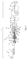
- FIG. 1 is a schematic representation of an installation for the manufacture of irrigation pipes of the drip type. Designated as a whole by the general numerical reference 1, this installation includes a feed station 5 in drippers 4 which is followed by an extrusion station 10 of the pipe 8 and a cooling station 25 of the pipe 8.
- the feed station 5 comprises a magazine 2 such as a centrifuge bowl which makes it possible to sort, guide and position drippers 4 in an accumulator device 6 in accordance with the position they will have once they will be introduced into the irrigation pipe 8.
- a magazine 2 such as a centrifuge bowl which makes it possible to sort, guide and position drippers 4 in an accumulator device 6 in accordance with the position they will have once they will be introduced into the irrigation pipe 8.
- This extrusion station 10 comprises a melting chamber 12 of the plastic material which feeds an assembly 14 provided with a die 16 inside which is provided a wire guide 18 arranged such that it leaves the die 16 a tubular blank 20.
- the blank 20 is pulled by pulling stations 22a and 22b passing through calibration means 24 and a cooling station 25 constituted by a cooling tank 26.
- the pipe 8 is wound on a coil 28.
- the wire guide 18 has an axial passage inside which is disposed a guide support 30 which extends to the inside of the calibrator 24a of the calibration means 24. Guiding support 30 receives the drippers 4 from the magazine 2 via the storage device 6.
- a metering device-driver 32 provided, in the example shown, metering rollers 34 assisted by air jets 36 is provided to advance the drippers 4 to the inside of the calibrator 24a.
- the pipe blank 20 the diameter of which is calibrated by the calibrator 24a, is brought into contact with the dripper 4 at the moment when its consistency is still pasty with the aid of a pressure roller 30a. which ensures the thermo-welding of the upper face 38 of the dripper 4 against the inner wall of the blank 20.
- the pipe 8 On leaving the calibration means 24 and the cooling tank 26, the pipe 8 enters a drilling station 40 via the first pulling station 22a then out to enter the second pulling station 22b. In the drilling station 40, the pipe 8 is pierced with small holes made opposite the drippers 4 and through which the water will flow.
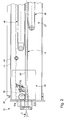
- the cooling tank 26 defines a hermetic enclosure containing a coolant.
- the upper wall 42 of the cooling tank 26 defines, with the upper surface of the coolant, a cavity 44.
- Suction means (not shown) are provided to create a vacuum in this cavity 44.
- a stabilization station 27 is disposed downstream of the welding means 30, 30a in the cooling tank 26 to empty.
- the stabilization station 27 is immersed in the coolant.
- the stabilizing station 27 comprises an upper endless belt 46 and a lower endless belt 48 whose respective upper and lower strands are substantially straight and parallel. These strands are applied against opposite faces of the pipe 8 without affecting its dimensional characteristics and while providing frictionless driving and guiding of the pipe 8.
- the installation 1 is provided with a detection device 50 which detects, in the cooling liquid, the emission of gas bubbles 52 through the wall 54 of the pipe 8.
- the gas bubbles 52 are atmospheric air bubbles.
- the detection device 50 comprises a camera 56 which takes images of a zone of coolant, called the analysis zone 58, located at least partly above a section of the pipe 8.
- the analysis zone 58 is defined globally by the field of view of the camera 56 and by the transparency of the coolant.
- the camera 56 is arranged on a support 60 which is fixed on the outer face 62 of a side wall 64 of the cooling tank 26. Said side wall 64 has, opposite the lens 66 of the camera 56 , a transparent portion called viewing window 68.
- the side wall 64 has an opening 70 vis-à-vis the objective 66 and the viewing window 68 is constituted by a transparent mirror 72 which is attached to the side of the inner face 74 of the side wall 64.
- the transparent glass 72 is sealed, so that the coolant can not flow through the opening 70 of the side wall 64.
- the detection device 50 comprises an electronic analysis circuit 76 which collects the images taken by the camera 56 and which applies, preferably to each image taken by the camera 56, an image processing algorithm making it possible to detect the presence of air bubbles 52 on the image.
- this algorithm comprises, for each image analyzed, at least one step of comparing the analyzed image with a reference image corresponding to the presence of at least one bubble 52 in the coolant.
- the analysis circuit 76 has in memory the image of a bubble 52, more particularly the image of an air bubble 52 such as that which may appear in case of micro-perforation and / or micro -fissure in the wall 54 of the pipe 8.
- the analysis circuit 76 is therefore able to identify, by analogy, the round shape of a bubble 52 in the images taken by the camera 56.
- the image processing algorithm implemented by the analysis circuit 76 can use a reference image that corresponds to a lack of bubble.
- the camera assembly 56 and electronic analysis circuit 76 is constituted by a suitable vision system such as those manufactured by the company Matsushita Electric Works, under the brand name "NAIS" or "Panasonic".
- the cooling tank 26 is equipped with cleaning means 78 of the inner face 80 of the transparent glass 72, so as to avoid the deposition of impurities and / or air bubbles on this inner face 80, which could affect the quality of the images taken by the camera 56.
- the cleaning means 78 here comprise a nozzle 82 which is carried by the side wall 64 of the cooling tank 26 and which is oriented towards the inner face 80 of the transparent glass 72.
- the nozzle 82 is connected through the side wall 64 , to a source of pressurized liquid, so as to produce a flow of liquid which is projected towards the transparent ice 72 and which scans at least a portion of the transparent ice 72.
- the nozzle 82 is connected, for example, to the device (not shown) which supplies the cooling tank 26 with cooling liquid.
- the detection device 50 is equipped with lighting means 84 of the coolant so as to improve the quality of the images taken by the camera 56.
- These lighting means 84 are constituted here by a device annular light diffusion which is centered on the axis of the lens 66 of the camera 56 and which is mounted around this lens 66, outside the cooling tank 26.
- Detection device 50 here controls a signaling device 86 which produces a warning signal when an air bubble 52 is detected.
- the warning signal is, for example, a light signal and / or a sound signal, allowing an operator to detect the appearance and origin of a malfunction of the installation 1.
- the operation of the detection device 50 according to the invention is as follows.
- the camera 50 takes images of the analysis zone 58.
- the electronic analysis circuit 76 compares these images with a reference image. In the absence of perforations and / or cracks in the pipe 8, the images taken by the camera 56 do not include any bubbles 52.
- the electronic analysis circuit 76 can deduce the presence of at least one micro-perforation or micro-crack.
- the scanning electronics 76 controls the signaling device 86 to produce a warning signal.
- the detection method used by the installation 1 according to the invention can be applied to products other than irrigation pipes 8, in particular to any hollow element comprising a peripheral wall 54 which delimits a chamber interior subjected to the pressure of a gas such as atmospheric air.
- This process comprises, successively, a prior step during which the hollow element 8 is immersed in a tank 26 containing a liquid; an analysis step during which the presence of gas bubbles 52 is sought in the tray 26; and a detection step in which an alert signal is generated, in the case where at least one gas bubble 52 is detected at the analyzing step, so as to signal the presence of perforations and / or cracks in the wall 54 of the hollow element 8.
- the detection device 50 of the installation 10 according to the invention is used to detect a modification of the geometry of the pipe 8, with respect to a reference geometry.
- changing the geometry means a change in the shape and / or size of the pipe, for example an increase or decrease in its diameter.
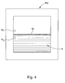
- the images taken by the camera 56 cover at least a portion of the pipe 8, and the analysis circuit 76 applies, to each image taken by the camera 56, an image processing algorithm comprising at least one step of comparing the image taken by the camera 56 with a reference image corresponding to a reference geometry of the pipe 8, ie a step of determining the position of the outer surface 8a of the pipe 8 with respect to one or more markers M1, M2 of the camera 56 as can be seen in Figure 4 which shows schematically a control screen 56a of the camera.
- This embodiment makes it possible to use the detection device 50 to detect stability problems, or even malfunctions, in the process. manufacturing pipe 8, which result, for example, in a decrease in the outer diameter of the pipe 8. It thus improves the reliability of the installation 1 and the quality of the pipe 8 produced.
- the detection device 50 may be dedicated to the detection of a modification of the geometry of the pipe 8, without taking care of the detection of gas bubbles.
- the installation 1 according to the invention may also comprise a first detection device 50 dedicated to the detection of gas bubbles 52 and a second detection device dedicated to the detection of a geometry modification of the pipe 8.
Abstract
Description
La présente invention est relative à une installation de fabrication de tuyaux d'irrigation goutte-à-goutte. Plus particulièrement, l'invention concerne une telle installation comprenant des moyens de contrôle en temps réel de la qualité des tuyaux produits. L'invention concerne notamment une telle installation comprenant un bac de refroidissement muni d'un dispositif de détection de fissures et de perforations, notamment de micro-perforations, dans la paroi du tuyau fabriqué,.The present invention relates to a plant for manufacturing drip irrigation pipes. More particularly, the invention relates to such an installation comprising means for real-time control of the quality of the pipes produced. The invention relates in particular to such an installation comprising a cooling tank provided with a device for detecting cracks and perforations, in particular micro-perforations, in the wall of the manufactured pipe.
L'invention concerne aussi un procédé pour la détection de fissures et de perforations dans la paroi d'un élément creux.The invention also relates to a method for the detection of cracks and perforations in the wall of a hollow element.
Il est de technique courante d'utiliser, pour certaines irrigations, des tuyaux dits "goutte-à-goutte". Il s'agit de tuyaux dont la paroi est percée, à des intervalles de distance fixés à l'avance, par des trous de petit diamètre par lesquels l'eau s'écoule dans le sol. Pour contrôler avec précision le débit des trous, on prévoit au niveau de chaque trou un limiteur de débit couramment appelé "goutteur" qui se compose d'une pièce en matière plastique creuse qui est collée sur la paroi interne du tuyau.It is common practice to use, for some irrigations, pipes called "drip". These are pipes whose wall is pierced, at intervals of distance fixed in advance, by small diameter holes through which the water flows into the ground. To precisely control the flow of holes, there is provided at each hole a flow limiter commonly called "dripper" which consists of a hollow plastic part which is glued to the inner wall of the pipe.
Dans les installations de fabrication de tuyaux d'irrigation goutte-à-goutte conventionelles, des goutteurs sont amenés de manière régulière dans un poste d'extrusion comprenant des moyens d'extrusion, de calibrage et de soudage à partir d'un dispositif d'approvisionnement tel qu'un bol centrifugeur et orienteur permettant de fournir des goutteurs selon une orientation déterminée. Dans le poste d'extrusion, le tuyau est produit en continu, calibré, et les goutteurs sont soudés à intervalles réguliers à la paroi intérieure du tuyau encore chaud afin qu'ils se collent contre celle-ci en fondant localement.In conventional drip irrigation pipe-making plants, drippers are routinely fed to an extrusion station including extrusion, calibration and welding means from an apparatus for drip irrigation. supply such as a centrifuge bowl and orientator to supply drippers in a specific orientation. In the extrusion station, the pipe is produced continuously, calibrated, and the drippers are welded at regular intervals to the inner wall of the still hot pipe so that they stick against it by melting locally.
Après que les goutteurs ont été soudés à la face intérieure du tuyau, le tuyau est tiré par des moyens de traction à travers un bac de refroidissement à eau qui permet de refroidir l'ensemble tuyau-goutteurs, de sorte que la forme finale du tuyau est figée.After the drippers have been welded to the inside of the pipe, the pipe is pulled by pulling means through a water cooling pan which allows the pipe-dripper assembly to cool, so that the final shape of the pipe is frozen.
A la suite du bac de refroidissement, un poste de perçage réalise un trou dans la paroi du tuyau, au droit de chaque goutteur.Following the cooling tank, a drilling station makes a hole in the wall of the pipe, to the right of each dripper.
Il a été constaté que ce type d'installation pouvait produire des tuyaux dont la paroi comporte des défauts du type micro-perforations et/ou fissures. L'apparition des micro-perforations et des fissures peut avoir plusieurs origines. Elle peut être due notamment à la présence de poussières dans le poste d'extrusion, à une granulométrie trop élevée du noir de carbone présent dans la matière du tuyau, à un encrassage des moyens de calibrage, ou encore à un défaut lors du soudage des goutteurs.It was found that this type of installation could produce pipes whose wall has micro-perforations type defects and / or cracks. The appearance of micro-perforations and cracks can have several origins. It may be due in particular to the presence of dust in the extrusion station, to a particle size too high carbon black present in the material of the pipe, to a fouling calibration means, or a fault when welding drippers.
Or, ces défauts ne sont généralement pas détectables à l'oeil nu, de sorte que des tuyaux peuvent être produits puis livrés au client sans que les défauts aient été détectés, et sans qu'il ait été remédié aux dysfonctionnements à l'origine de ces défauts. Ces défauts se révèlent alors, après l'installation des tuyaux sur le terrain, par exemple sous la forme d'une consommation anormalement élevée en liquide d'irrigation.However, these defects are generally not detectable to the naked eye, so that pipes can be produced and delivered to the customer without the defects have been detected, and without it being remedied to the malfunctions causing the these defects. These defects are then revealed after the installation of the pipes in the field, for example in the form of an abnormally high consumption of irrigation liquid.
La présente invention a pour but de remédier aux inconvénients susmentionnés ainsi qu'à d'autres encore en fournissant une installation de fabrication de tuyaux d'irrigation goutte à goutte munie de moyens pour détecter la présence de perforations et/ou de fissures dans la paroi des tuyaux d'irrigation fabriqués.It is an object of the present invention to overcome the aforementioned and other disadvantages by providing a drip irrigation pipe manufacturing facility having means for detecting the presence of perforations and / or cracks in the wall. irrigation pipes manufactured.
La présente invention a également pour but de fournir une telle installation mettant en oeuvre des moyens simples et peu coûteux.The present invention also aims to provide such an installation using simple and inexpensive means.
La présente invention a également pour but de fournir une telle installation comprenant des moyens de contrôle en temps réel de la qualité des tuyaux produits et notamment de la stabilité dimensionnelle de la production.The present invention also aims to provide such an installation comprising means for real-time control of the quality of the pipes produced and in particular the dimensional stability of the production.
A cet effet, la présente invention propose selon un premier aspect une installation pour la fabrication d'un tuyau d'irrigation goutte à goutte comprenant un poste d'alimentation en goutteurs suivi d'un poste d'extrusion comprenant des moyens d'extrusion, des moyens de calibrage du tuyau et des moyens pour le soudage des goutteurs à la paroi intérieure du tuyau, et suivi d'un poste de refroidissement du tuyau, du type dans lequel le poste de refroidissement comporte un bac de refroidissement contenant un liquide de refroidissement dans lequel le tuyau est immergé, caractérisée en ce qu'il est prévu un dispositif de détection qui détecte, dans le liquide de refroidissement, l'émission de bulles de gaz à travers la paroi du tuyau, de manière à en déduire la présence de perforations et/ou de fissures dans la paroi du tuyau.For this purpose, the present invention provides in a first aspect an installation for the manufacture of a drip irrigation pipe comprising a feed station in drippers followed by an extrusion station comprising extrusion means, means for calibrating the pipe and means for welding the drippers to the inner wall of the pipe, followed by a cooling station for the pipe, of the type in which the cooling station comprises a cooling tank containing a coolant in which the pipe is immersed, characterized in that there is provided a detection device which detects, in the cooling liquid, the emission of gas bubbles through the wall of the pipe, so as to deduce the presence of perforations and / or cracks in the pipe wall.
Grâce à ces caractéristiques, les défauts dans le tuyau sont facilement détectés ce qui permet de prendre des mesures correctrices dans l'installation pour garantir la qualité de fabrication.Thanks to these characteristics, the faults in the pipe are easily detected which allows corrective measures to be taken in the installation to guarantee the quality of manufacture.
Selon des caractéristiques complémentaires de l'invention, le dispositif de détection comporte une caméra qui prend des images d'une zone du liquide de refroidissement, dite zone d'analyse, située au moins en partie au-dessus d'un tronçon du tuyau et un circuit électronique d'analyse qui détermine la présence des bulles de gaz à partir des images prises par la caméra. De préférence, le circuit d'analyse applique, à chaque image prise par la caméra, un algorithme de traitement d'image comportant au moins une étape de comparaison de l'image prise par la caméra avec une image de référence correspondant à la présence d'au moins une bulle de gaz.According to complementary features of the invention, the detection device comprises a camera that takes images of a zone of the coolant, called the analysis zone, located at least partly above a section of the pipe and an electronic analysis circuit which determines the presence of the gas bubbles from the images taken by the camera. Preferably, the analysis circuit applies, to each image taken by the camera, a processing algorithm image comprising at least one step of comparing the image taken by the camera with a reference image corresponding to the presence of at least one gas bubble.
Selon une caractéristique avantageuse de l'invention, la zone d'analyse est située au voisinage de l'extrémité aval des moyens de calibrage, ce qui permet de détecter de manière précoce l'apparition de micro-perforations et/ou fissures dans la paroi du tuyau.According to an advantageous characteristic of the invention, the analysis zone is situated in the vicinity of the downstream end of the calibration means, which makes it possible to detect early the appearance of micro-perforations and / or cracks in the wall. of the pipe.
Selon une autre caractéristique avantageuse de l'invention, le bac de refroidissement comporte une portion de paroi transparente, dite fenêtre de visualisation, et l'objectif de la caméra est agencé derrière la fenêtre de visualisation, à l'extérieur du bac de refroidissement. Cet agencement particulier facilite l'implantation de la caméra dans l'installation, notamment sur le plan de l'étanchéité, et il permet d'obtenir des images de qualité suffisante pour le traitement des images par le circuit électronique d'analyse.According to another advantageous characteristic of the invention, the cooling tank comprises a transparent wall portion, called the viewing window, and the objective of the camera is arranged behind the viewing window, outside the cooling tank. This particular arrangement facilitates the implantation of the camera in the installation, particularly in terms of sealing, and it provides images of sufficient quality for processing images by the electronic analysis circuit.
Selon encore d'autres caractéristiques avantageuses de l'invention, des moyens de nettoyage de la fenêtre de visualisation et des moyens d'éclairage du liquide de refroidissement sont prévus de manière à assurer une bonne qualité des images prises par la caméra.According to still other advantageous features of the invention, means for cleaning the viewing window and cooling liquid lighting means are provided so as to ensure good quality of the images taken by the camera.
De plus, selon un mode de réalisation avantageux de l'invention, le dispositif de détection est lié à un dispositif de signalisation et à une unité centrale de manière à commander par exemple le changement de bobine lorsqu'une bulle de gaz est détectée de manière à perdre le moins possible de tube.In addition, according to an advantageous embodiment of the invention, the detection device is connected to a signaling device and to a central unit so as to control, for example, the change of coil when a gas bubble is detected in such a way to lose the least possible tube.
La présente invention propose aussi un procédé pour la détection de perforations et/ou de fissures dans la paroi d'un élément creux comportant une paroi périphérique qui délimite une chambre intérieure soumise à la pression d'un gaz tel que de l'air atmosphérique, caractérisé en ce qu'il comporte les étapes successives suivantes :
- une étape préalable au cours de laquelle l'élément creux est plongé dans un bac contenant un liquide,
- une étape d'analyse au cours de laquelle la présence de bulles de gaz est recherchée dans le bac, et
- une étape de détection au cours de laquelle un signal d'alerte est produit, dans le cas où au moins une bulle de gaz est détectée à l'étape d'analyse, de manière à signaler la présence de perforations et/ou de fissures dans la paroi de l'élément creux.
- a preliminary step during which the hollow element is immersed in a tank containing a liquid,
- an analysis step during which the presence of gas bubbles is sought in the tank, and
- a detection step during which an alert signal is produced, in the case where at least one gas bubble is detected in the analysis step, so as to signal the presence of perforations and / or cracks in the wall of the hollow element.
Selon un deuxième aspect l'invention à pour objet Installation pour la fabrication d'un tuyau d'irrigation goutte à goutte comprenant un poste d'alimentation en goutteurs suivi d'un poste d'extrusion comprenant des moyens d'extrusion, des moyens de calibrage du tuyau et des moyens pour le soudage des goutteurs à la paroi intérieure du tuyau , et suivi d'un poste de refroidissement du tuyau, du type dans lequel le poste de refroidissement comporte un bac de refroidissement contenant un liquide de refroidissement dans lequel le tuyau est immergé, caractérisée en ce qu'il est prévu un dispositif de détection comportant une caméra qui prend des images d'une zone du liquide de refroidissement, dite zone d'analyse, comprenant au moins une portion de tuyau et un circuit électronique d'analyse qui détecte une modification de la géométrie du tuyau, par rapport à une géométrie de référence, de manière à en déduire un problème de stabilité de fabrication du tuyau à partir des images prises par la caméra.According to a second aspect, the invention relates to an installation for the manufacture of a drip irrigation pipe comprising a feed station in drippers followed by an extrusion station comprising extrusion means, means for calibrating the pipe and means for welding the drippers to the inner wall of the pipe, and monitoring a cooling station of the pipe, of the type in which the cooling station comprises a cooling tank containing a coolant in which the pipe is immersed, characterized in that there is provided a detection device comprising a camera which takes images of a zone of the cooling liquid, called the analysis zone, comprising at least a portion of pipe and a circuit analysis electronics which detects a change in the geometry of the pipe, with respect to a reference geometry, so as to deduce a manufacturing stability problem of the pipe from the images taken by the camera.
D'autres caractéristiques et avantages de la présente invention ressortiront plus clairement de la description détaillée qui suit d'un exemple de réalisation de l'installation selon l'invention, cet exemple étant donné à titre purement illustratif et non limitatif seulement, en liaison avec les dessins annexés sur lesquels :
- la figure 1 est une représentation schématique d'une installation pour la fabrication de tuyaux d'irrigation du type goutte-à-goutte selon l'invention ;
- la figure 2 est une vue selon le plan de coupe 2-2 qui représente schématiquement l'agencement du dispositif de détection au voisinage du poste d'extrusion de l'installation de la figure 1 ;
- la figure 3 est une vue selon le plan de coupe 3-3 qui représente schématiquement le dispositif de détection de l'installation de la figure 1 ; et
- la figure 4 est une représentation schématique d'un écran de contrôle de la caméra utilisée dans l'installation de l'invention.
- Figure 1 is a schematic representation of an installation for the manufacture of irrigation pipes of the drip type according to the invention;
- Figure 2 is a view along section plane 2-2 which schematically shows the arrangement of the detection device in the vicinity of the extrusion station of the installation of Figure 1;
- Figure 3 is a view along the section plane 3-3 which schematically shows the detection device of the installation of Figure 1; and
- Figure 4 is a schematic representation of a camera control screen used in the installation of the invention.
La figure 1 est une représentation schématique d'une installation pour la fabrication de tuyaux d'irrigation du type goutte-à-goutte. Désignée dans son ensemble par la référence numérique générale 1, cette installation comprend notamment un poste d'alimentation 5 en goutteurs 4 qui est suivi d'un poste d'extrusion 10 du tuyau 8 et d'un poste de refroidissement 25 du tuyau 8.Figure 1 is a schematic representation of an installation for the manufacture of irrigation pipes of the drip type. Designated as a whole by the general
Le poste d'alimentation 5 comprend un magasin 2 tel qu'un bol centrifugeur qui permet de trier, d'orienter et de positionner des goutteurs 4 dans un dispositif accumulateur 6 en conformité avec la position qu'ils devront avoir une fois qu'ils seront introduits dans le tuyau d'irrigation 8.The feed station 5 comprises a
A la suite du dispositif accumulateur 6 est disposé le poste d'extrusion 10. Ce poste d'extrusion 10 comprend une chambre de fusion 12 de la matière plastique qui alimente un ensemble 14 pourvu d'une filière 16 à l'intérieur de laquelle est prévu un guide fil 18 disposé de telle façon qu'il sorte de la filière 16 une ébauche tubulaire 20. L'ébauche 20 est tirée par des postes de traction 22a et 22b en passant à travers des moyens de calibrage 24 et un poste de refroidissement 25 constitué par un bac de refroidissement 26. Au-delà du poste de traction 22b, le tuyau 8 est enroulé sur une bobine 28.Following the
Dans la suite de la description, on utilisera à titre non limitatif une orientation de l'amont vers l'aval conformément au sens de défilement du tuyau 8 dans l'installation 1.In the remainder of the description, use will be made without limitation of an orientation from upstream to downstream in accordance with the direction of travel of the
Une telle disposition est classique dans la technique de fabrication des tuyaux en matière plastique. Pour fixer les goutteurs 4, il est prévu que le guide fil 18 présente un passage axial à l'intérieur duquel est disposé un support de guidage 30 qui s'étend jusqu'à l'intérieur du calibreur 24a des moyens de calibrage 24. Le support de guidage 30 reçoit les goutteurs 4 à partir du magasin 2 via le dispositif accumulateur 6. Un dispositif doseur-entraîneur 32 muni, dans l'exemple représenté, de galets doseurs 34 assistés par des jets d'air 36 est prévu pour faire avancer les goutteurs 4 jusqu'à l'intérieur du calibreur 24a.Such an arrangement is conventional in the technique of manufacturing plastic pipes. To fix the
Dans le calibreur 24a, l'ébauche de tuyau 20, dont le diamètre est calibré par le calibreur 24a, est amenée en contact avec le goutteur 4 au moment où sa consistance est encore pâteuse à l'aide d'un galet presseur 30a, ce qui assure le thermo-soudage de la face supérieure 38 du goutteur 4 contre la paroi intérieure de l'ébauche 20. En sortant des moyens de calibrage 24 et du bac de refroidissement 26, le tuyau 8 pénètre dans un poste de perçage 40 via le premier poste de traction 22a puis en sort pour pénétrer dans le deuxième poste de traction 22b. Dans le poste de perçage 40, le tuyau 8 est percé de petits trous pratiqués en regard des goutteurs 4 et par lesquels l'eau s'écoulera.In the
Tel que représenté sur la figure 2, le bac de refroidissement 26 délimite une enceinte hermétique contenant un liquide de refroidissement. La paroi supérieure 42 du bac de refroidissement 26 délimite, avec la surface supérieure du liquide de refroidissement, une cavité 44. Des moyens d'aspiration (non représentés) sont prévus pour créer un vide dans cette cavité 44.As shown in Figure 2, the
Selon le mode de réalisation représenté ici, un poste de stabilisation 27 est disposé en aval des moyens de soudage 30, 30a dans le bac de refroidissement 26 à vide. Dans l'exemple illustré, le poste de stabilisation 27 est immergé dans le liquide de refroidissement. Le poste de stabilisation 27 comprend une courroie sans fin supérieure 46 et une courroie sans fin inférieure 48 dont les brins inférieur et supérieur respectifs sont sensiblement rectilignes et parallèles. Ces brins sont appliqués contre des faces opposées du tuyau 8 sans affecter ses caractéristiques dimensionnelles et tout en assurant un entraînement et un guidage sans frottement du tuyau 8.According to the embodiment shown here, a
Conformément aux enseignements de l'invention, l'installation 1 est pourvue d'un dispositif de détection 50 qui détecte, dans le liquide de refroidissement, l'émission de bulles de gaz 52 à travers la paroi 54 du tuyau 8. Comme la partie intérieure du tuyau 8 est ici soumise globalement à la pression de l'air atmosphérique, les bulles de gaz 52 sont des bulles d'air atmosphérique.In accordance with the teachings of the invention, the
Comme on l'a représenté sur la figure 3, le dispositif de détection 50 comporte une caméra 56 qui prend des images d'une zone de liquide de refroidissement, dite zone d'analyse 58, située au moins en partie au-dessus d'un tronçon du tuyau 8. La zone d'analyse 58 est définie globalement par le champ de vision de la caméra 56 et par la transparence du liquide de refroidissement.As shown in FIG. 3, the
La caméra 56 est agencée sur un support 60 qui est fixé sur la face externe 62 d'une paroi latérale 64 du bac de refroidissement 26. Ladite paroi latérale 64 comporte, en vis-à-vis de l'objectif 66 de la caméra 56, une portion transparente dite fenêtre de visualisation 68.The
Selon le mode de réalisation représenté, la paroi latérale 64 comporte une ouverture 70 en vis-à-vis de l'objectif 66 et la fenêtre de visualisation 68 est constituée par une glace transparente 72 qui est rapportée, du côté de la face interne 74 de la paroi latérale 64. Bien entendu, la glace transparente 72 est fixée de manière étanche, de sorte que le liquide de refroidissement ne puisse s'écouler à travers l'ouverture 70 de la paroi latérale 64.According to the embodiment shown, the
Le dispositif de détection 50 comporte un circuit électronique d'analyse 76 qui collecte les images prises par la caméra 56 et qui applique, de préférence à chaque image prise par la caméra 56, un algorithme de traitement d'image permettant de déceler la présence de bulles d'air 52 sur l'image. Avantageusement, cet algorithme comporte, pour chaque image analysée, au moins une étape de comparaison de l'image analysée avec une image de référence correspondant à la présence d'au moins une bulle 52 dans le liquide de refroidissement. Ainsi, le circuit d'analyse 76 possède en mémoire l'image d'une bulle 52, plus particulièrement l'image d'une bulle d'air 52 telle que celle qui peut apparaître en cas de micro-perforation et/ou de micro-fissure dans la paroi 54 du tuyau 8. Le circuit d'analyse 76 est donc en mesure de repérer, par analogie, la forme ronde d'une bulle 52 dans les images prises par la caméra 56.The
Selon une variante de réalisation de l'invention, l'algorithme de traitement d'image mis en oeuvre par le circuit d'analyse 76 peut utiliser une image de référence qui correspond à une absence de bulle.According to an alternative embodiment of the invention, the image processing algorithm implemented by the
L'ensemble caméra 56 et circuit électronique d'analyse 76 est constitué par un système de vision approprié tel que ceux qui sont fabriqués par l'entreprise Matsushita Electric Works, sous la marque « NAIS » ou « Panasonic ».The
Avantageusement, le bac de refroidissement 26 est équipé de moyens de nettoyage 78 de la face interne 80 de la glace transparente 72, de manière à éviter le dépôt d'impuretés et/ou de bulles d'air sur cette face interne 80, ce qui pourrait nuire à la qualité des images prises par la caméra 56.Advantageously, the
Les moyens de nettoyage 78 comportent ici une buse 82 qui est portée par la paroi latérale 64 du bac de refroidissement 26 et qui est orientée vers la face interne 80 de la glace transparente 72. La buse 82 est raccordée, à travers la paroi latérale 64, à une source de liquide sous pression, de manière à produire un flux de liquide qui est projeté vers la glace transparente 72 et qui balaye au moins une partie de la glace transparente 72. La buse 82 est raccordée, par exemple, au dispositif (non représenté) qui alimente le bac de refroidissement 26 en liquide de refroidissement.The cleaning means 78 here comprise a
On note que les moyens de nettoyage 78 sont facultatifs.It is noted that the cleaning means 78 are optional.
Selon un mode de réalisation avantageux, le dispositif de détection 50 est équipé de moyens d'éclairage 84 du liquide de refroidissement de manière à améliorer la qualité des images prises par la caméra 56. Ces moyens d'éclairage 84 sont constitués ici par un dispositif annulaire de diffusion lumineuse qui est centré sur l'axe de l'objectif 66 de la caméra 56 et qui est monté autour de cet objectif 66, à l'extérieur du bac de refroidissement 26.According to an advantageous embodiment, the
Le dispositif de détection 50 commande ici un dispositif de signalisation 86 qui produit un signal d'avertissement lorsqu'une bulle d'air 52 est détectée. Le signal d'avertissement est, par exemple, un signal lumineux et/ou un signal sonore, permettant à un opérateur de déceler l'apparition et l'origine d'un dysfonctionnement de l'installation 1.
De préférence, le dispositif de détection 50 est lié à une unité centrale 88 qui par exemple, commande automatiquement le changement de bobine 28 lorsqu'une bulle d'air 52 est détectée.Preferably, the
Le fonctionnement du dispositif de détection 50 selon l'invention est le suivant.The operation of the
Pendant la fabrication du tuyau 8, la caméra 50 prend des images de la zone d'analyse 58. Le circuit électronique d'analyse 76 compare ces images avec une image de référence. En l'absence de perforations et/ou de fissures dans le tuyau 8, les images prises par la caméra 56 ne comprennent aucune bulle 52.During the manufacture of the
Comme l'intérieur du tuyau 8 est soumis à la pression atmosphérique de l'air ambiant, dès qu'une micro-perforation ou une micro-fissure apparaît dans la paroi 54 du tuyau 8, au moins une bulle d'air 52 s'échappe du tuyau 8 à travers cette micro-perforation ou cette micro-fissure, au moment où le tuyau 8 pénètre dans le liquide de refroidissement. Cette bulle d'air 52 remonte ensuite jusqu'à la surface du liquide de refroidissement.As the inside of the
Dès qu'une bulle d'air 52 s'échappe du tuyau 8, elle apparaît sur les images prises par la caméra 56, de sorte que le circuit électronique d'analyse 76 peut en déduire la présence d'au moins une micro-perforation ou micro-fissure. Le circuit électronique d'analyse 76 commande alors le dispositif de signalisation 86 pour qu'il produise un signal d'avertissement.As soon as an
L'unité centrale 88 est informée, ici par le dispositif de signalisation 86, de la présence d'au moins une micro-perforation et/ou une micro-fissure, de sorte qu'elle provoque le changement de bobine 28.The
On note que le procédé de détection mis en oeuvre par l'installation 1 selon l'invention peut s'appliquer à des produits autres que des tuyaux d'irrigation 8, en particulier à tout élément creux comportant une paroi périphérique 54 qui délimite une chambre intérieure soumise à la pression d'un gaz tel que de l'air atmosphérique.It is noted that the detection method used by the
Ce procédé comporte, successivement, une étape préalable au cours de laquelle l'élément creux 8 est plongé dans un bac 26 contenant un liquide ; une étape d'analyse au cours de laquelle la présence de bulles de gaz 52 est recherchée dans le bac 26 ; et une étape de détection au cours de laquelle un signal d'alerte est produit, dans le cas où au moins une bulle de gaz 52 est détectée à l'étape d'analyse, de manière à signaler la présence de perforations et/ou de fissures dans la paroi 54 de l'élément creux 8.This process comprises, successively, a prior step during which the
Selon un mode de réalisation avantageux, le dispositif de détection 50 de l'installation 10 selon l'invention est utilisé pour détecter une modification de la géométrie du tuyau 8, par rapport à une géométrie de référence. Par modification de la géométrie on entend une modification de la forme et/ou d'une dimension du tuyau, par exemple une augmentation ou une diminution de son diamètre. A cet effet, les images prises par la caméra 56 recouvrent au moins une portion du tuyau 8, et le circuit d'analyse 76 applique, à chaque image prise par la caméra 56, un algorithme de traitement d'image comportant au moins soit une étape de comparaison de l'image prise par la caméra 56 avec une image de référence correspondant à une géométrie de référence du tuyau 8, soit une étape de détermination de la position de la surface externe 8a du tuyau 8 par rapport à un ou plusieurs marqueurs M1, M2 de la caméra 56 comme cela est visible à la figure 4 qui représente schématiquement un écran de contrôle 56a de la caméra.According to an advantageous embodiment, the
Ce mode de réalisation permet d'exploiter le dispositif de détection 50 pour détecter des problèmes de stabilité, voire des dysfonctionnements, dans le processus de fabrication du tuyau 8, qui se traduisent, par exemple, par une diminution du diamètre extérieur du tuyau 8. Il permet donc d'améliorer la fiabilité de l'installation 1 et la qualité du tuyau 8 produit.This embodiment makes it possible to use the
Bien entendu, le dispositif de détection 50 peut être dédié à la détection d'une modification de la géométrie du tuyau 8, sans s'occuper de la détection de bulles de gaz. L'installation 1 selon l'invention peut aussi comporter un premier dispositif de détection 50 dédié à la détection des bulles de gaz 52 et un second dispositif de détection dédié à la détection d'une modification de géométrie du tuyau 8.Of course, the
Il va de soi que la présente invention n'est pas limitée au mode de réalisation qui vient d'être décrit et que diverses modifications et variantes simples peuvent être envisagées par l'homme du métier sans sortir du cadre de l'invention tel que défini par les revendications annexées. On pourra notamment prévoir d'utiliser, à la place d'un bac de refroidissement à vide comme cela vient d'être décrit, un bac de refroidissement sous pression atmosphérique. Un gaz sera injecté dans le tube en formation, par exemple depuis l'arrière de la tête d'extrusion pour que le tube conserve sa forme avant qu'il soit refroidi.It goes without saying that the present invention is not limited to the embodiment which has just been described and that various modifications and simple variants can be envisaged by those skilled in the art without departing from the scope of the invention as defined by the appended claims. In particular, it will be possible to use, in place of a vacuum cooling tank as has just been described, a cooling tank under atmospheric pressure. A gas will be injected into the forming tube, for example from the back of the extrusion head so that the tube retains its shape before it is cooled.
Claims (19)
Priority Applications (6)
| Application Number | Priority Date | Filing Date | Title |
|---|---|---|---|
| AT05005241T ATE393383T1 (en) | 2005-03-10 | 2005-03-10 | DEVICE FOR PRODUCING HOSES AND CORRESPONDING METHOD FOR DEFECTING DEFECTS |
| ES05005241T ES2307085T3 (en) | 2005-03-10 | 2005-03-10 | INSTALLATION FOR THE MANUFACTURE OF TUBES AND PROCEDURE FOR DETECTION OF DEFECTS ASSOCIATED WITH THE SAME. |
| EP05005241A EP1701147B1 (en) | 2005-03-10 | 2005-03-10 | Apparatus for producing pipes and method for corresponding fault detection |
| DE602005006232T DE602005006232T2 (en) | 2005-03-10 | 2005-03-10 | Device for producing hoses and corresponding method for fault detection |
| US11/370,946 US20060202381A1 (en) | 2005-03-10 | 2006-03-09 | Pipe manufacturing installation and associated defect detection method |
| CY20081100763T CY1108208T1 (en) | 2005-03-10 | 2008-07-22 | PIPE CONSTRUCTION INSTALLATION AND RELATED METHOD OF DETECTION DETECTION |
Applications Claiming Priority (1)
| Application Number | Priority Date | Filing Date | Title |
|---|---|---|---|
| EP05005241A EP1701147B1 (en) | 2005-03-10 | 2005-03-10 | Apparatus for producing pipes and method for corresponding fault detection |
Publications (2)
| Publication Number | Publication Date |
|---|---|
| EP1701147A1 true EP1701147A1 (en) | 2006-09-13 |
| EP1701147B1 EP1701147B1 (en) | 2008-04-23 |
Family
ID=34934174
Family Applications (1)
| Application Number | Title | Priority Date | Filing Date |
|---|---|---|---|
| EP05005241A Active EP1701147B1 (en) | 2005-03-10 | 2005-03-10 | Apparatus for producing pipes and method for corresponding fault detection |
Country Status (6)
| Country | Link |
|---|---|
| US (1) | US20060202381A1 (en) |
| EP (1) | EP1701147B1 (en) |
| AT (1) | ATE393383T1 (en) |
| CY (1) | CY1108208T1 (en) |
| DE (1) | DE602005006232T2 (en) |
| ES (1) | ES2307085T3 (en) |
Cited By (19)
| Publication number | Priority date | Publication date | Assignee | Title |
|---|---|---|---|---|
| CN102306440A (en) * | 2011-08-25 | 2012-01-04 | 李晓亮 | Building with automatic alarm |
| CN102680220A (en) * | 2012-05-10 | 2012-09-19 | 张振华 | Method and device for measuring hydraulic characteristic of trickle irrigation emitter |
| WO2012160121A1 (en) | 2011-05-26 | 2012-11-29 | Maillefer Sa | A system for manufacturing an irrigation pipe and a device and method for detecting holes in the wall of an irrigation pipe |
| EP2441561A3 (en) * | 2010-10-18 | 2014-01-22 | INOEX GmbH | Method and device for starting a pipe extrusion line |
| CN103557996A (en) * | 2013-11-14 | 2014-02-05 | 河北科技大学 | Device and method for visually detecting leakproofness of four-station bearing part |
| CN104913882A (en) * | 2014-03-14 | 2015-09-16 | 天津市华旭盛泰科技有限公司 | Novel drip irrigation pipe detecting water tank |
| CN109459222A (en) * | 2018-12-04 | 2019-03-12 | 大禹节水(天津)有限公司 | A kind of drip irrigation zone performance of anti-blockage detection method |
| US10285342B2 (en) | 2013-08-12 | 2019-05-14 | Rain Bird Corporation | Elastomeric emitter and methods relating to same |
| US10330559B2 (en) | 2014-09-11 | 2019-06-25 | Rain Bird Corporation | Methods and apparatus for checking emitter bonds in an irrigation drip line |
| US10375904B2 (en) | 2016-07-18 | 2019-08-13 | Rain Bird Corporation | Emitter locating system and related methods |
| US10420293B2 (en) | 2013-10-22 | 2019-09-24 | Rain Bird Corporation | Methods and apparatus for transporting emitters and/or manufacturing drip line |
| US10440903B2 (en) | 2012-03-26 | 2019-10-15 | Rain Bird Corporation | Drip line emitter and methods relating to same |
| US10626998B2 (en) | 2017-05-15 | 2020-04-21 | Rain Bird Corporation | Drip emitter with check valve |
| US10631473B2 (en) | 2013-08-12 | 2020-04-28 | Rain Bird Corporation | Elastomeric emitter and methods relating to same |
| USD883048S1 (en) | 2017-12-12 | 2020-05-05 | Rain Bird Corporation | Emitter part |
| US10842090B2 (en) | 2006-02-22 | 2020-11-24 | Rain Bird Corporation | Drip emitter |
| CN112747673A (en) * | 2020-12-25 | 2021-05-04 | 中国人民解放军陆军工程大学 | Calibration method of monocular multiline structured light sensor based on calibration cylinder |
| US11051466B2 (en) | 2017-01-27 | 2021-07-06 | Rain Bird Corporation | Pressure compensation members, emitters, drip line and methods relating to same |
| US11185021B2 (en) | 2012-03-26 | 2021-11-30 | Rain Bird Corporation | Elastomeric emitter and methods relating to same |
Families Citing this family (13)
| Publication number | Priority date | Publication date | Assignee | Title |
|---|---|---|---|---|
| US8302887B2 (en) | 2005-03-31 | 2012-11-06 | Rain Bird Corporation | Drip emitter |
| US8628032B2 (en) | 2008-12-31 | 2014-01-14 | Rain Bird Corporation | Low flow irrigation emitter |
| US20130248622A1 (en) | 2012-03-26 | 2013-09-26 | Jae Yung Kim | Drip line and emitter and methods relating to same |
| US9485923B2 (en) | 2012-03-26 | 2016-11-08 | Rain Bird Corporation | Elastomeric emitter and methods relating to same |
| ES2613070T3 (en) * | 2012-11-09 | 2017-05-22 | Abu Dhabi Polymers Company Limited (Borouge) | Drip irrigation pipe comprising a polymer composition comprising a multimodal polyethylene base resin |
| CN103047948A (en) * | 2013-01-06 | 2013-04-17 | 高利强 | Non-contact detection system for punching position of water dropper of drip irrigation tube |
| US9872444B2 (en) | 2013-03-15 | 2018-01-23 | Rain Bird Corporation | Drip emitter |
| USD811179S1 (en) | 2013-08-12 | 2018-02-27 | Rain Bird Corporation | Emitter part |
| CH708592A1 (en) * | 2013-09-18 | 2015-03-31 | Fischer Connectors Holding Ag | Apparatus and method for leak testing a cable. |
| ES2726668T3 (en) | 2013-10-24 | 2019-10-08 | Jain Irrigation Systems Ltd | Method and system of detection of blowouts in pipes / tubes |
| US11307114B2 (en) | 2018-12-17 | 2022-04-19 | National Oilwell Varco, L.P. | Pressure-based flaw detection |
| DE102020103687B4 (en) * | 2020-02-12 | 2022-05-05 | Battenfeld-Cincinnati Germany Gmbh | Device for starting an extrusion process |
| US20220189220A1 (en) * | 2020-12-10 | 2022-06-16 | Ford Global Technologies, Llc | Vision system for a vehicle coolant system |
Citations (7)
| Publication number | Priority date | Publication date | Assignee | Title |
|---|---|---|---|---|
| US3302450A (en) * | 1963-02-27 | 1967-02-07 | Int Standard Electric Corp | Device for testing tubes for leaks |
| EP0353982A2 (en) * | 1988-08-03 | 1990-02-07 | KiTECHNOLOGY B.V. | Apparatus for forming plastics coated tube |
| US5170658A (en) * | 1991-01-28 | 1992-12-15 | Thayer Thomas J | Bicycle tire leak detector apparatus |
| US5324371A (en) * | 1988-05-30 | 1994-06-28 | Hydro-Plan Engineering Ltd. | Process for producing a drip irrigation conduit |
| FR2727890A1 (en) * | 1994-12-07 | 1996-06-14 | Kertscher Sa E | METHOD OF MANUFACTURING DRIP IRRIGATION PIPES |
| JPH11264781A (en) * | 1998-03-18 | 1999-09-28 | Daido Steel Co Ltd | Airtightness inspecting device and its bubble sensing method |
| JP2000334812A (en) * | 1999-05-27 | 2000-12-05 | Sekisui Chem Co Ltd | Apparatus for producing extruded molding, appearance inspecting device for apparatus, and production of extruded molding using apparatus |
Family Cites Families (2)
| Publication number | Priority date | Publication date | Assignee | Title |
|---|---|---|---|---|
| US6748992B1 (en) * | 1999-01-29 | 2004-06-15 | Unicor Gmbh Rahn Plastmaschinen | Facility for manufacturing multilayered composite tubes |
| JP3573023B2 (en) * | 1999-09-30 | 2004-10-06 | 富士写真光機株式会社 | Endoscope with objective lens moving mechanism |
-
2005
- 2005-03-10 EP EP05005241A patent/EP1701147B1/en active Active
- 2005-03-10 ES ES05005241T patent/ES2307085T3/en active Active
- 2005-03-10 AT AT05005241T patent/ATE393383T1/en not_active IP Right Cessation
- 2005-03-10 DE DE602005006232T patent/DE602005006232T2/en active Active
-
2006
- 2006-03-09 US US11/370,946 patent/US20060202381A1/en not_active Abandoned
-
2008
- 2008-07-22 CY CY20081100763T patent/CY1108208T1/en unknown
Patent Citations (8)
| Publication number | Priority date | Publication date | Assignee | Title |
|---|---|---|---|---|
| US3302450A (en) * | 1963-02-27 | 1967-02-07 | Int Standard Electric Corp | Device for testing tubes for leaks |
| US5324371A (en) * | 1988-05-30 | 1994-06-28 | Hydro-Plan Engineering Ltd. | Process for producing a drip irrigation conduit |
| EP0353982A2 (en) * | 1988-08-03 | 1990-02-07 | KiTECHNOLOGY B.V. | Apparatus for forming plastics coated tube |
| US5170658A (en) * | 1991-01-28 | 1992-12-15 | Thayer Thomas J | Bicycle tire leak detector apparatus |
| FR2727890A1 (en) * | 1994-12-07 | 1996-06-14 | Kertscher Sa E | METHOD OF MANUFACTURING DRIP IRRIGATION PIPES |
| US5744779A (en) * | 1994-12-07 | 1998-04-28 | E. Kertscher S.A. | Method for manufacturing drip irrigation tubes |
| JPH11264781A (en) * | 1998-03-18 | 1999-09-28 | Daido Steel Co Ltd | Airtightness inspecting device and its bubble sensing method |
| JP2000334812A (en) * | 1999-05-27 | 2000-12-05 | Sekisui Chem Co Ltd | Apparatus for producing extruded molding, appearance inspecting device for apparatus, and production of extruded molding using apparatus |
Non-Patent Citations (2)
| Title |
|---|
| PATENT ABSTRACTS OF JAPAN vol. 1999, no. 14 22 December 1999 (1999-12-22) * |
| PATENT ABSTRACTS OF JAPAN vol. 2000, no. 15 6 April 2001 (2001-04-06) * |
Cited By (24)
| Publication number | Priority date | Publication date | Assignee | Title |
|---|---|---|---|---|
| US10842090B2 (en) | 2006-02-22 | 2020-11-24 | Rain Bird Corporation | Drip emitter |
| EP2441561A3 (en) * | 2010-10-18 | 2014-01-22 | INOEX GmbH | Method and device for starting a pipe extrusion line |
| WO2012160121A1 (en) | 2011-05-26 | 2012-11-29 | Maillefer Sa | A system for manufacturing an irrigation pipe and a device and method for detecting holes in the wall of an irrigation pipe |
| CN102306440A (en) * | 2011-08-25 | 2012-01-04 | 李晓亮 | Building with automatic alarm |
| US10440903B2 (en) | 2012-03-26 | 2019-10-15 | Rain Bird Corporation | Drip line emitter and methods relating to same |
| US11185021B2 (en) | 2012-03-26 | 2021-11-30 | Rain Bird Corporation | Elastomeric emitter and methods relating to same |
| CN102680220A (en) * | 2012-05-10 | 2012-09-19 | 张振华 | Method and device for measuring hydraulic characteristic of trickle irrigation emitter |
| CN102680220B (en) * | 2012-05-10 | 2014-07-09 | 鲁东大学 | Method and device for measuring hydraulic characteristic of trickle irrigation emitter |
| US10285342B2 (en) | 2013-08-12 | 2019-05-14 | Rain Bird Corporation | Elastomeric emitter and methods relating to same |
| US10631473B2 (en) | 2013-08-12 | 2020-04-28 | Rain Bird Corporation | Elastomeric emitter and methods relating to same |
| US10420293B2 (en) | 2013-10-22 | 2019-09-24 | Rain Bird Corporation | Methods and apparatus for transporting emitters and/or manufacturing drip line |
| CN103557996A (en) * | 2013-11-14 | 2014-02-05 | 河北科技大学 | Device and method for visually detecting leakproofness of four-station bearing part |
| CN104913882A (en) * | 2014-03-14 | 2015-09-16 | 天津市华旭盛泰科技有限公司 | Novel drip irrigation pipe detecting water tank |
| US10330559B2 (en) | 2014-09-11 | 2019-06-25 | Rain Bird Corporation | Methods and apparatus for checking emitter bonds in an irrigation drip line |
| US11422055B2 (en) | 2014-09-11 | 2022-08-23 | Rain Bird Corporation | Methods and apparatus for checking emitter bonds in an irrigation drip line |
| US10375904B2 (en) | 2016-07-18 | 2019-08-13 | Rain Bird Corporation | Emitter locating system and related methods |
| US10750684B2 (en) | 2016-07-18 | 2020-08-25 | Rain Bird Corporation | Emitter locating system and related methods |
| US11051466B2 (en) | 2017-01-27 | 2021-07-06 | Rain Bird Corporation | Pressure compensation members, emitters, drip line and methods relating to same |
| US10626998B2 (en) | 2017-05-15 | 2020-04-21 | Rain Bird Corporation | Drip emitter with check valve |
| USD883048S1 (en) | 2017-12-12 | 2020-05-05 | Rain Bird Corporation | Emitter part |
| USD978637S1 (en) | 2017-12-12 | 2023-02-21 | Rain Bird Corporation | Emitter part |
| CN109459222A (en) * | 2018-12-04 | 2019-03-12 | 大禹节水(天津)有限公司 | A kind of drip irrigation zone performance of anti-blockage detection method |
| CN112747673A (en) * | 2020-12-25 | 2021-05-04 | 中国人民解放军陆军工程大学 | Calibration method of monocular multiline structured light sensor based on calibration cylinder |
| CN112747673B (en) * | 2020-12-25 | 2022-10-25 | 中国人民解放军陆军工程大学 | Calibration method of monocular multiline structured light sensor based on calibration cylinder |
Also Published As
| Publication number | Publication date |
|---|---|
| US20060202381A1 (en) | 2006-09-14 |
| ATE393383T1 (en) | 2008-05-15 |
| DE602005006232T2 (en) | 2009-05-20 |
| ES2307085T3 (en) | 2008-11-16 |
| CY1108208T1 (en) | 2014-02-12 |
| EP1701147B1 (en) | 2008-04-23 |
| DE602005006232D1 (en) | 2008-06-05 |
Similar Documents
| Publication | Publication Date | Title |
|---|---|---|
| EP1701147B1 (en) | Apparatus for producing pipes and method for corresponding fault detection | |
| EP0989931B1 (en) | Nozzle for blow moulding plastic containers and installation provided with same | |
| EP1817955B2 (en) | Installation and method for the production of pipes for drip irrigation | |
| EP1268158B1 (en) | Method and production line for the continuous manufacture of plastic tubes with bi-axial drawing | |
| EP1541013A1 (en) | Method of fabrication of drip irrigation conduits | |
| EP2212095A2 (en) | Installation and method for conveying preforms | |
| EP3535190A1 (en) | Device and method for pressure-packaging a container to be processed and associated pressure-packaging machine | |
| CA1305336C (en) | Process and apparatus for measuring the elasticity of a superficial stratum, especially of the skin | |
| EP1541014B1 (en) | Method of fabrication of drip irrigation conduits | |
| FR2788706A1 (en) | Spray producer for spraying liquid has holes in walls of supply chamber allowing introduction of nozzle with supply holes inside supply chamber | |
| EP3157732B1 (en) | Method and system | |
| EP1602273B1 (en) | Device for producing drip irrigation hoses | |
| EP4214001A1 (en) | Apparatus with drum for separating packagings and material adhering thereto, with improved environmental impact | |
| CH617128A5 (en) | Method for cooling a tube or a profile made from plastic coming out of an extrusion head, and device for implementing the method | |
| FR2558592A1 (en) | Methods and devices for continuously checking the leaktightness of plastic extruded pipes. | |
| EP0013237A1 (en) | Method and apparatus for fiberizing attenuable materials by means of a gas stream | |
| EP1339274B1 (en) | Production line of a drip irrigation pipe and method for using said production line | |
| FR2768417A1 (en) | Pneumatic conveyor for lightweight containers e.g. plastic bottles | |
| EP2726855B1 (en) | Detection device and machine for coating a planar substrate provided with same | |
| FR2845467A1 (en) | METHOD FOR CONTROLLING AN EXTRUSION ROD, SUCH AS A GLUE ROD, AND A SIZING DEVICE USING THE SAME | |
| FR2806957A1 (en) | Continuous production of bi=axially oriented plastic tubing includes monitoring axial force applied to extruded blank so force kept constant | |
| FR3123647A1 (en) | Method for controlling a fiber-drawing device | |
| WO2015015105A1 (en) | Automatic method and facility for characterising and/or sorting packages | |
| FR3139125A1 (en) | Product dispensing device equipped with a piston and its manufacturing process. | |
| FR3105196A1 (en) | Checking the tightness of products |
Legal Events
| Date | Code | Title | Description |
|---|---|---|---|
| PUAI | Public reference made under article 153(3) epc to a published international application that has entered the european phase |
Free format text: ORIGINAL CODE: 0009012 |
|
| AK | Designated contracting states |
Kind code of ref document: A1 Designated state(s): AT BE BG CH CY CZ DE DK EE ES FI FR GB GR HU IE IS IT LI LT LU MC NL PL PT RO SE SI SK TR |
|
| AX | Request for extension of the european patent |
Extension state: AL BA HR LV MK YU |
|
| 17P | Request for examination filed |
Effective date: 20070313 |
|
| AKX | Designation fees paid |
Designated state(s): AT BE BG CH CY CZ DE DK EE ES FI FR GB GR HU IE IS IT LI LT LU MC NL PL PT RO SE SI SK TR |
|
| 17Q | First examination report despatched |
Effective date: 20070504 |
|
| GRAP | Despatch of communication of intention to grant a patent |
Free format text: ORIGINAL CODE: EPIDOSNIGR1 |
|
| GRAS | Grant fee paid |
Free format text: ORIGINAL CODE: EPIDOSNIGR3 |
|
| GRAA | (expected) grant |
Free format text: ORIGINAL CODE: 0009210 |
|
| AK | Designated contracting states |
Kind code of ref document: B1 Designated state(s): AT BE BG CH CY CZ DE DK EE ES FI FR GB GR HU IE IS IT LI LT LU MC NL PL PT RO SE SI SK TR |
|
| REG | Reference to a national code |
Ref country code: GB Ref legal event code: FG4D Free format text: NOT ENGLISH |
|
| REG | Reference to a national code |
Ref country code: CH Ref legal event code: EP |
|
| REF | Corresponds to: |
Ref document number: 602005006232 Country of ref document: DE Date of ref document: 20080605 Kind code of ref document: P |
|
| REG | Reference to a national code |
Ref country code: IE Ref legal event code: FG4D |
|
| REG | Reference to a national code |
Ref country code: CH Ref legal event code: PK Free format text: LE NOM DU TITULAIRE A ETE CORRIGE. |
|
| REG | Reference to a national code |
Ref country code: GR Ref legal event code: EP Ref document number: 20080401916 Country of ref document: GR |
|
| PG25 | Lapsed in a contracting state [announced via postgrant information from national office to epo] |
Ref country code: SI Free format text: LAPSE BECAUSE OF FAILURE TO SUBMIT A TRANSLATION OF THE DESCRIPTION OR TO PAY THE FEE WITHIN THE PRESCRIBED TIME-LIMIT Effective date: 20080423 |
|
| NLV1 | Nl: lapsed or annulled due to failure to fulfill the requirements of art. 29p and 29m of the patents act | ||
| PG25 | Lapsed in a contracting state [announced via postgrant information from national office to epo] |
Ref country code: FI Free format text: LAPSE BECAUSE OF FAILURE TO SUBMIT A TRANSLATION OF THE DESCRIPTION OR TO PAY THE FEE WITHIN THE PRESCRIBED TIME-LIMIT Effective date: 20080423 Ref country code: PT Free format text: LAPSE BECAUSE OF FAILURE TO SUBMIT A TRANSLATION OF THE DESCRIPTION OR TO PAY THE FEE WITHIN THE PRESCRIBED TIME-LIMIT Effective date: 20080923 Ref country code: BG Free format text: LAPSE BECAUSE OF FAILURE TO SUBMIT A TRANSLATION OF THE DESCRIPTION OR TO PAY THE FEE WITHIN THE PRESCRIBED TIME-LIMIT Effective date: 20080723 Ref country code: NL Free format text: LAPSE BECAUSE OF FAILURE TO SUBMIT A TRANSLATION OF THE DESCRIPTION OR TO PAY THE FEE WITHIN THE PRESCRIBED TIME-LIMIT Effective date: 20080423 |
|
| REG | Reference to a national code |
Ref country code: CH Ref legal event code: NV Representative=s name: ICB INGENIEURS CONSEILS EN BREVETS SA |
|
| REG | Reference to a national code |
Ref country code: ES Ref legal event code: FG2A Ref document number: 2307085 Country of ref document: ES Kind code of ref document: T3 |
|
| PG25 | Lapsed in a contracting state [announced via postgrant information from national office to epo] |
Ref country code: AT Free format text: LAPSE BECAUSE OF FAILURE TO SUBMIT A TRANSLATION OF THE DESCRIPTION OR TO PAY THE FEE WITHIN THE PRESCRIBED TIME-LIMIT Effective date: 20080423 Ref country code: PL Free format text: LAPSE BECAUSE OF FAILURE TO SUBMIT A TRANSLATION OF THE DESCRIPTION OR TO PAY THE FEE WITHIN THE PRESCRIBED TIME-LIMIT Effective date: 20080423 |
|
| REG | Reference to a national code |
Ref country code: IE Ref legal event code: FD4D |
|
| PG25 | Lapsed in a contracting state [announced via postgrant information from national office to epo] |
Ref country code: IS Free format text: LAPSE BECAUSE OF FAILURE TO SUBMIT A TRANSLATION OF THE DESCRIPTION OR TO PAY THE FEE WITHIN THE PRESCRIBED TIME-LIMIT Effective date: 20080823 |
|
| PG25 | Lapsed in a contracting state [announced via postgrant information from national office to epo] |
Ref country code: DK Free format text: LAPSE BECAUSE OF FAILURE TO SUBMIT A TRANSLATION OF THE DESCRIPTION OR TO PAY THE FEE WITHIN THE PRESCRIBED TIME-LIMIT Effective date: 20080423 Ref country code: CZ Free format text: LAPSE BECAUSE OF FAILURE TO SUBMIT A TRANSLATION OF THE DESCRIPTION OR TO PAY THE FEE WITHIN THE PRESCRIBED TIME-LIMIT Effective date: 20080423 Ref country code: IE Free format text: LAPSE BECAUSE OF FAILURE TO SUBMIT A TRANSLATION OF THE DESCRIPTION OR TO PAY THE FEE WITHIN THE PRESCRIBED TIME-LIMIT Effective date: 20080423 Ref country code: SE Free format text: LAPSE BECAUSE OF FAILURE TO SUBMIT A TRANSLATION OF THE DESCRIPTION OR TO PAY THE FEE WITHIN THE PRESCRIBED TIME-LIMIT Effective date: 20080723 Ref country code: LT Free format text: LAPSE BECAUSE OF FAILURE TO SUBMIT A TRANSLATION OF THE DESCRIPTION OR TO PAY THE FEE WITHIN THE PRESCRIBED TIME-LIMIT Effective date: 20080423 |
|
| PG25 | Lapsed in a contracting state [announced via postgrant information from national office to epo] |
Ref country code: RO Free format text: LAPSE BECAUSE OF FAILURE TO SUBMIT A TRANSLATION OF THE DESCRIPTION OR TO PAY THE FEE WITHIN THE PRESCRIBED TIME-LIMIT Effective date: 20080423 Ref country code: SK Free format text: LAPSE BECAUSE OF FAILURE TO SUBMIT A TRANSLATION OF THE DESCRIPTION OR TO PAY THE FEE WITHIN THE PRESCRIBED TIME-LIMIT Effective date: 20080423 |
|
| PLBE | No opposition filed within time limit |
Free format text: ORIGINAL CODE: 0009261 |
|
| STAA | Information on the status of an ep patent application or granted ep patent |
Free format text: STATUS: NO OPPOSITION FILED WITHIN TIME LIMIT |
|
| 26N | No opposition filed |
Effective date: 20090126 |
|
| PG25 | Lapsed in a contracting state [announced via postgrant information from national office to epo] |
Ref country code: EE Free format text: LAPSE BECAUSE OF FAILURE TO SUBMIT A TRANSLATION OF THE DESCRIPTION OR TO PAY THE FEE WITHIN THE PRESCRIBED TIME-LIMIT Effective date: 20080423 |
|
| BERE | Be: lapsed |
Owner name: THE THOMAS MACHINES SA Effective date: 20090331 |
|
| PG25 | Lapsed in a contracting state [announced via postgrant information from national office to epo] |
Ref country code: MC Free format text: LAPSE BECAUSE OF NON-PAYMENT OF DUE FEES Effective date: 20090331 |
|
| GBPC | Gb: european patent ceased through non-payment of renewal fee |
Effective date: 20090310 |
|
| REG | Reference to a national code |
Ref country code: FR Ref legal event code: ST Effective date: 20091130 |
|
| PG25 | Lapsed in a contracting state [announced via postgrant information from national office to epo] |
Ref country code: BE Free format text: LAPSE BECAUSE OF NON-PAYMENT OF DUE FEES Effective date: 20090331 |
|
| PG25 | Lapsed in a contracting state [announced via postgrant information from national office to epo] |
Ref country code: FR Free format text: LAPSE BECAUSE OF NON-PAYMENT OF DUE FEES Effective date: 20091123 Ref country code: GB Free format text: LAPSE BECAUSE OF NON-PAYMENT OF DUE FEES Effective date: 20090310 |
|
| PG25 | Lapsed in a contracting state [announced via postgrant information from national office to epo] |
Ref country code: LU Free format text: LAPSE BECAUSE OF NON-PAYMENT OF DUE FEES Effective date: 20090310 |
|
| PG25 | Lapsed in a contracting state [announced via postgrant information from national office to epo] |
Ref country code: HU Free format text: LAPSE BECAUSE OF FAILURE TO SUBMIT A TRANSLATION OF THE DESCRIPTION OR TO PAY THE FEE WITHIN THE PRESCRIBED TIME-LIMIT Effective date: 20081024 |
|
| PG25 | Lapsed in a contracting state [announced via postgrant information from national office to epo] |
Ref country code: TR Free format text: LAPSE BECAUSE OF FAILURE TO SUBMIT A TRANSLATION OF THE DESCRIPTION OR TO PAY THE FEE WITHIN THE PRESCRIBED TIME-LIMIT Effective date: 20080423 |
|
| PGFP | Annual fee paid to national office [announced via postgrant information from national office to epo] |
Ref country code: DE Payment date: 20200218 Year of fee payment: 16 Ref country code: IT Payment date: 20200218 Year of fee payment: 16 Ref country code: GR Payment date: 20200227 Year of fee payment: 16 |
|
| PGFP | Annual fee paid to national office [announced via postgrant information from national office to epo] |
Ref country code: CY Payment date: 20200219 Year of fee payment: 16 |
|
| PGFP | Annual fee paid to national office [announced via postgrant information from national office to epo] |
Ref country code: ES Payment date: 20200401 Year of fee payment: 16 |
|
| REG | Reference to a national code |
Ref country code: DE Ref legal event code: R119 Ref document number: 602005006232 Country of ref document: DE |
|
| PG25 | Lapsed in a contracting state [announced via postgrant information from national office to epo] |
Ref country code: CY Free format text: LAPSE BECAUSE OF NON-PAYMENT OF DUE FEES Effective date: 20210310 |
|
| PG25 | Lapsed in a contracting state [announced via postgrant information from national office to epo] |
Ref country code: DE Free format text: LAPSE BECAUSE OF NON-PAYMENT OF DUE FEES Effective date: 20211001 |
|
| PG25 | Lapsed in a contracting state [announced via postgrant information from national office to epo] |
Ref country code: GR Free format text: LAPSE BECAUSE OF NON-PAYMENT OF DUE FEES Effective date: 20211008 |
|
| PG25 | Lapsed in a contracting state [announced via postgrant information from national office to epo] |
Ref country code: IT Free format text: LAPSE BECAUSE OF NON-PAYMENT OF DUE FEES Effective date: 20210310 |
|
| REG | Reference to a national code |
Ref country code: ES Ref legal event code: FD2A Effective date: 20220523 |
|
| PG25 | Lapsed in a contracting state [announced via postgrant information from national office to epo] |
Ref country code: ES Free format text: LAPSE BECAUSE OF NON-PAYMENT OF DUE FEES Effective date: 20210311 |
|
| PGFP | Annual fee paid to national office [announced via postgrant information from national office to epo] |
Ref country code: CH Payment date: 20230402 Year of fee payment: 19 |