EP1700996A2 - Tape drum for a darkening device, like a roller shutter - Google Patents
Tape drum for a darkening device, like a roller shutter Download PDFInfo
- Publication number
- EP1700996A2 EP1700996A2 EP06002040A EP06002040A EP1700996A2 EP 1700996 A2 EP1700996 A2 EP 1700996A2 EP 06002040 A EP06002040 A EP 06002040A EP 06002040 A EP06002040 A EP 06002040A EP 1700996 A2 EP1700996 A2 EP 1700996A2
- Authority
- EP
- European Patent Office
- Prior art keywords
- antenna
- gurtwickler
- housing
- pivot axis
- module
- Prior art date
- Legal status (The legal status is an assumption and is not a legal conclusion. Google has not performed a legal analysis and makes no representation as to the accuracy of the status listed.)
- Granted
Links
Images


Classifications
-
- H—ELECTRICITY
- H01—ELECTRIC ELEMENTS
- H01Q—ANTENNAS, i.e. RADIO AERIALS
- H01Q3/00—Arrangements for changing or varying the orientation or the shape of the directional pattern of the waves radiated from an antenna or antenna system
- H01Q3/02—Arrangements for changing or varying the orientation or the shape of the directional pattern of the waves radiated from an antenna or antenna system using mechanical movement of antenna or antenna system as a whole
- H01Q3/04—Arrangements for changing or varying the orientation or the shape of the directional pattern of the waves radiated from an antenna or antenna system using mechanical movement of antenna or antenna system as a whole for varying one co-ordinate of the orientation
-
- E—FIXED CONSTRUCTIONS
- E06—DOORS, WINDOWS, SHUTTERS, OR ROLLER BLINDS IN GENERAL; LADDERS
- E06B—FIXED OR MOVABLE CLOSURES FOR OPENINGS IN BUILDINGS, VEHICLES, FENCES OR LIKE ENCLOSURES IN GENERAL, e.g. DOORS, WINDOWS, BLINDS, GATES
- E06B9/00—Screening or protective devices for wall or similar openings, with or without operating or securing mechanisms; Closures of similar construction
- E06B9/56—Operating, guiding or securing devices or arrangements for roll-type closures; Spring drums; Tape drums; Counterweighting arrangements therefor
- E06B9/78—Operating, guiding or securing devices or arrangements for roll-type closures; Spring drums; Tape drums; Counterweighting arrangements therefor for direct manual operation, e.g. by tassels, by handles
-
- H—ELECTRICITY
- H01—ELECTRIC ELEMENTS
- H01Q—ANTENNAS, i.e. RADIO AERIALS
- H01Q1/00—Details of, or arrangements associated with, antennas
- H01Q1/12—Supports; Mounting means
- H01Q1/22—Supports; Mounting means by structural association with other equipment or articles
-
- H—ELECTRICITY
- H01—ELECTRIC ELEMENTS
- H01Q—ANTENNAS, i.e. RADIO AERIALS
- H01Q3/00—Arrangements for changing or varying the orientation or the shape of the directional pattern of the waves radiated from an antenna or antenna system
- H01Q3/02—Arrangements for changing or varying the orientation or the shape of the directional pattern of the waves radiated from an antenna or antenna system using mechanical movement of antenna or antenna system as a whole
-
- E—FIXED CONSTRUCTIONS
- E06—DOORS, WINDOWS, SHUTTERS, OR ROLLER BLINDS IN GENERAL; LADDERS
- E06B—FIXED OR MOVABLE CLOSURES FOR OPENINGS IN BUILDINGS, VEHICLES, FENCES OR LIKE ENCLOSURES IN GENERAL, e.g. DOORS, WINDOWS, BLINDS, GATES
- E06B9/00—Screening or protective devices for wall or similar openings, with or without operating or securing mechanisms; Closures of similar construction
- E06B9/56—Operating, guiding or securing devices or arrangements for roll-type closures; Spring drums; Tape drums; Counterweighting arrangements therefor
- E06B9/78—Operating, guiding or securing devices or arrangements for roll-type closures; Spring drums; Tape drums; Counterweighting arrangements therefor for direct manual operation, e.g. by tassels, by handles
- E06B2009/785—Operating, guiding or securing devices or arrangements for roll-type closures; Spring drums; Tape drums; Counterweighting arrangements therefor for direct manual operation, e.g. by tassels, by handles by belts, straps, bands, tapes, cords, tassels
Definitions
- the invention relates to a belt winder for a dimming device such as a roller shutter according to the preamble of claim 1.
- the motor-operated belt winder in question is widely used for retrofitting, i. H.
- For the exchange of manually operated Gurtwickler this is provided in a first variant of the installation of the motor-operated Gurtwicklers in an existing belt box.
- Auiputztechnik known that are possibly designed as a swivel.
- Gurtwickler Motorized Gurtwickler are now increasingly equipped with automatic functions.
- One of these automatic functions is that the Gurtwickler is automatically operated at predetermined times.
- the Gurtwickler is equipped with a time module.
- the known Gurtwickler (DE 10 2004 012 354 A1), from which the invention proceeds, has a drive arrangement and a control arrangement, wherein the control arrangement has a configured as Funkuhmiodul time module.
- the radio clock module of the known Gurtwicklers is adapted to receive one of the above long-wave time signals to determine the current time via radio.
- an antenna is provided which is regularly configured as a ferrite antenna.
- the disadvantage of the above application of a ferrite antenna is their high directivity, so that in unfavorable installation position of Gurtwicklers the reception of the time signal is of poor quality. In the worst case, this leads to the reception of a faulty time signal and as a result to the determination of a faulty current time.
- the remote control device has a time module configured as a radio clock module and transmits the corresponding time information by radio to the stationary belt winder or the stationary belt winder. Due to the mobility of the remote control device, it is readily possible to ensure optimum reception of the time signal. However, a disadvantage is the additional implementation effort, especially if a remote control device, for example, for cost reasons, is not desired.
- the invention is based on the problem of designing the known Gurtwickler and further educate, that the reliability is increased in terms of the proper operation of the time module.
- the antenna of the time module is arranged so adjustable over a holding device that alignment of the antenna to optimize the reception of the time signal is possible.
- adjustable is meant here that the antenna can perform a relative movement relative to the Gurtwickler in the rest. This ensures that even with a fixed Gurtwickler optimal alignment of the antenna is ensured.
- the time module may be configured as a self-contained unit, which may be completely interchangeable as a module against another module, but it may also consist of several separate units. Furthermore, it can be provided that the time module comprises the antenna, or that the time module, the antenna, if necessary, in turn, is assigned as a separate unit,
- the antenna is preferably a ferrite antenna, since this allows a particularly compact construction. But there are also other embodiments for the antenna conceivable.
- a particularly advantageous alignment behavior can be achieved according to claim 5 characterized in that the antenna is pivotable about a pivot axis.
- the pivoting about a single pivot axis or two preferably mutually perpendicularly oriented pivot axes (claim 7) is conceivable.
- the preferred embodiments according to claim 8 allow the alignment of the antenna with minimal effort.
- Essential here is the fact that the alignment is not associated with a complex disassembly process.
- Aligning the antenna is particularly convenient for the user when information about the respective current reception level of the time signal is visible during the alignment of the antenna via a display on Gurtwickler (claim 12). As a result, in particular, the time required for aligning the antenna can be significantly reduced.
- the Gurtwickler shown in the drawing is intended for a darkening device such as a blind, a blind, an awning o.
- the Gurtwickler is equipped with a housing 1 and with a drive assembly 2 located in the housing 1.
- the housing 1 it must not necessarily to act a completely closed housing 1.
- the term "housing” also includes a frame which accommodates the drive arrangement 2.
- the drive assembly 2 preferably has a reel 3 for winding a webbing 4, an electric drive motor 5 and a reduction gear 6 coupling to the reel 3. These components of the drive assembly 2 are merely indicated in the drawing. With regard to a preferred embodiment of the drive assembly 2 may be made to the German Utility Model 297 22 936.2 of the Applicant. The content of this utility model is in this respect made to the full extent the subject of the present application.
- the Gurtwickler is equipped with a control assembly 7, which is arranged in the illustrated and so far preferred embodiment in the housing 1. But it can also be provided that the control arrangement 7 is arranged on the housing 1. This is the case, for example, if the control arrangement 7 is constructed in a plurality of modules which can each be plugged onto the housing 1.
- the control arrangement 7 has a time module 8, which is designed as a radio clock module.
- the time module 8 is a DCF module.
- a time signal for determining the current time can be received via radio.
- the time module 8 is associated with an antenna 9 for receiving the time signal.
- the antenna 9 can also be an integral part of the time module 9.
- the antenna 9 is preferably designed as a ferrite antenna. This is also the case with the illustrated preferred embodiment.
- the antenna 9 of the time module 8 is arranged so adjustable about a holding device 10 that an alignment of the antenna 9 to Optimization of the reception of the time signal is possible. This can be seen from a synopsis of FIGS. 1 and 3 and will be explained in more detail below,
- Ausrhmngs form the housing 1 in the installed state, at least in most cases arranged in a masonry recess.
- Belt winder of this type are often employed in retrofitting existing dimming devices to replace existing mechanical winder.
- the main advantage of such a Gurtwicklers with electric motor is that it readily substitutes in the most standardized masonry recess for the purely mechanical Gurtwickler place. The exchange is very easy.
- the Gurtwickler but also be designed as a surface-mounted device. Such Gurtwickler be used accordingly when a masonry recess is not available or, for example, for reasons of cost, should not be provided.
- a Gurtwicklers designed as a radio clock module time module 8
- the antenna 9 forcibly disposed in close proximity to the masonry.
- the antenna 9 in the proposed Gurtwickler can be aligned. Without aligning the antenna 9, reliable reception of the timing signal can not be ensured.
- the housing 1 has a front panel 11, the various control elements 12, a display 13 and an insertion channel 14 for the webbing 4 borders.
- the front panel 11 receives said elements 12, 13, 14.
- the controls 12 may be arranged on the front panel 11.
- the housing 1 thus has in any case a base body 15 and the above front panel 11. It may also be that the housing 1 consists of a plurality of further subcomponents.
- the antenna 9 is arranged in the housing 1. Particularly advantageous is the arrangement of the antenna 9 directly under the front panel 11, so that as few structural components of Gurtwicklers interfere with the reception of the time signal. In the illustrated preferred embodiment, it is further such that the antenna 9 is arranged in the region of the insertion channel 14 for the webbing 4. This is advantageous in that the antenna 9 is then located at a considerable distance from the drive arrangement 2 and its components disturbing or shielding the reception.
- the antenna 9 is pivotally adjustable about a pivot axis 16.
- the pivoting angle of the antenna 9 achievable with this is essentially dependent on the configuration of the housing 1. In the exemplary embodiment shown, the pivoting angle of the antenna 9 is approximately 12 °.
- the antenna 9 in the embodiment of the antenna 9 as a ferrite antenna, it is preferably such that the antenna 9 extends in the direction of a longitudinal axis 17, wherein the pivot axis 16 of the antenna 9 preferably extends perpendicular to the longitudinal axis 17 of the antenna 9.
- the pivot axis 16 of the antenna 9 extends in the installed state substantially in the vertical direction. This takes account of the fact that, in the orientation, it is primarily based on the fact that the longitudinal axis 17 of the antenna 9 assumes different orientations within a horizontal plane.
- the antenna 9 is pivotable about a further pivot axis, wherein the two pivot axes 16 are preferably aligned perpendicular to each other.
- the orientation of the antenna 9 is particularly easy to carry out insofar as the antenna 9 is adjustable, without the Gurtwickler, in particular the housing 9 or the front panel 11 of the housing 1, to dismantle.
- the housing 1, or the front panel 11, here has a recess 18, through which access to the adjustment of the antenna 9 is possible.
- the engagement profile 19 may also have a simple slot or other shape. This makes it possible, the alignment, so the adjustment of the antenna 9, with a simple tool such as a screwdriver o. The like. To accomplish. But it can also be provided that the holding device 10 is equipped with an actuating element for the adjustment of the antenna 9, whereby the adjustment of the antenna 9 would be possible without tools.
- the holding device 10 now has a stationary bearing element 20 for the pivotable mounting of a holding element 21.
- the holding element 21 is pivotable about the pivot axis 16.
- the holding element 21 is preferably clipped into the bearing element 20.
- the holding element 21 is equipped with a series of resilient hooks 23, which are in the installed state with a circular shoulder of the bearing element 20 in engagement.
- the bearing element 20 and the holding element 21 are engaged with one another via in each case one engagement surface and that the engagement surfaces extend substantially perpendicular to the pivot axis 16 of the holding element 21.
- these engagement surfaces are roughened in each case in order to increase the friction between these two components.
- the two engagement surfaces have mutually corresponding toothings, which in turn counteract the automatic, unwanted adjustment of the antenna 9.
- a further preferred embodiment leads to a particularly convenient alignment of the antenna 9.
- the control device 7 controls the display 13 so that during the alignment of the antenna 9 via the display 13, information about the respective current reception level of the time signal visible is.
- a numerical representation or a graphical representation for example, by a bar with depending on the current reception level changing length o. The like., Possible.
- the antenna 9 is motor-adjustable is particularly user-friendly.
- the control arrangement 7 then automatically adjusts the orientation of the antenna 9.
- the control arrangement 7 has a corresponding control circuit.
- the antenna 9 is adjusted by the control circuit as long as the current reception level of the time signal is maximum.
- the antenna 9 is connected via a connecting line, not shown, with the control arrangement 7 in the rest.
- an electrical connection 24 is provided on the holding device 10, which is connected via the connecting line to a terminal 25 of the control arrangement 7 accordingly.
- the Gurtwickler invention can also be equipped with a Funkfiem Kunststoffung for fenragesteverte triggering individual functions. If, at the same time, as described above, the drive motor 5 is designed as a DC motor (preferably 220 V), then there are special requirements for this radio remote control. In a DC motor, in fact, every time the commutator is reversed, a brush fire occurs which disturbs the radio transmission of the radio remote control.
- a DC motor in fact, every time the commutator is reversed, a brush fire occurs which disturbs the radio transmission of the radio remote control.
- the above disturbance of the radio remote control by the brush fire of the DC motor 5 can be reduced for example by a suitable choice of the frequency range of the radio remote control. But it is also possible to redundantly encode the signals of the radio remote control, so that the transmission is either error-resistant or that transmission errors are detected in any case.
- the radio signal is encoded via frequency modulation.
- the radio remote control is preferably a GFSK transceiver (Gaussian Frequency Shift Keying) with CRC coding (Cylic Redundancy Check) and with Manchester code collision detection.
- the above embodiment of a radio remote control is applicable to all areas of home automation, but in particular to the field of motor Gurtwickler for dimming devices such as a shutter.
Landscapes
- Engineering & Computer Science (AREA)
- Structural Engineering (AREA)
- Architecture (AREA)
- Civil Engineering (AREA)
- Support Of Aerials (AREA)
- Operating, Guiding And Securing Of Roll- Type Closing Members (AREA)
- Measuring Pulse, Heart Rate, Blood Pressure Or Blood Flow (AREA)
- Electric Clocks (AREA)
Abstract
Description
Die Erfindung betrifft einen Gurtwickler für eine Verdunkelungseinrichtung wie einen Rolladen gemäß dem Oberbegriff von Anspruch 1.The invention relates to a belt winder for a dimming device such as a roller shutter according to the preamble of
Der in Rede stehende, motorisch betätigte Gurtwickler findet in weitem Umfang Anwendung für die Nachrüstung, d. h. für den Austausch manuell betätigter Gurtwickler, Hierbei ist in einer ersten Variante der Einbau des motorisch betätigten Gurtwicklers in einem vorhandenen Gurtkasten vorgesehen. Es sind aber auch Auiputzgeräte bekannt, die ggf. als Schwenkwickler ausgestaltet sind.The motor-operated belt winder in question is widely used for retrofitting, i. H. For the exchange of manually operated Gurtwickler, this is provided in a first variant of the installation of the motor-operated Gurtwicklers in an existing belt box. But there are also Auiputzgeräte known that are possibly designed as a swivel.
Motorisch betätigte Gurtwickler sind heute zunehmend mit Automatikfunktionen ausgestattet. Eine dieser Automatikfunktionen besteht darin, daß der Gurtwickler zu vorbestimmten Zeiten automatisch betätigt wird. Hierfür ist der Gurtwickler mit einem Zeitmodul ausgestattet. Der bekannte Gurtwickler (DE 10 2004 012 354 A1), von dem die Erfindung ausgeht, weist eine Antriebsanordnung und eine Steuerungsanordnung auf, wobei die Steuerungsanordnung ein als Funkuhmiodul ausgestaltetes Zeitmodul aufweist.Motorized Gurtwickler are now increasingly equipped with automatic functions. One of these automatic functions is that the Gurtwickler is automatically operated at predetermined times. For this the Gurtwickler is equipped with a time module. The known Gurtwickler (DE 10 2004 012 354 A1), from which the invention proceeds, has a drive arrangement and a control arrangement, wherein the control arrangement has a configured as Funkuhmiodul time module.
In Deutschland verbreitet die Physikalisch-Technische Bundesanstalt (PTB) ein Zeitsignal über den Langwellensender DCF 77 im Dauerbetrieb. Eine entsprechende Einrichtung auf internationaler Basis ist der TDF-Langwellensender in Allouis, Frankreich.In Germany, the Physikalisch-Technische Bundesanstalt (PTB) distributes a time signal via the long-wave transmitter DCF 77 in continuous operation. A similar facility on an international basis is the TDF longwave transmitter in Allouis, France.
Das Funkuhrmodul des bekannten Gurtwicklers ist darauf eingerichtet, eines der obigen Langwellen-Zeitsignale zur Ermittlung der aktuellen Zeit über Funk zu empfangen. Hierfür ist eine Antenne vorgesehen, die regelmäßig als Ferrit-Antenne ausgestaltet ist. Der Nachteil der obigen Anwendung einer Ferrit-Antenne besteht in ihrer hohen Richtwirkung, so daß bei ungünstiger Einbaulage des Gurtwicklers der Empfang des Zeitsignals von nur schlechter Qualität ist. Dies führt im ungünstigsten Fall zum Empfang eines fehlerhaften Zeitsignals und im Ergebnis zur Ermittlung einer fehlerhaften aktuellen Zeit.The radio clock module of the known Gurtwicklers is adapted to receive one of the above long-wave time signals to determine the current time via radio. For this purpose, an antenna is provided which is regularly configured as a ferrite antenna. The disadvantage of the above application of a ferrite antenna is their high directivity, so that in unfavorable installation position of Gurtwicklers the reception of the time signal is of poor quality. In the worst case, this leads to the reception of a faulty time signal and as a result to the determination of a faulty current time.
Die Gefahr eines unzureichendes Empfangs des Zeitsignals ist bei dem bekannten Gurtwickler besonders ausgeprägt, da er ortsfest und unbeweglich am Mauerwerk oder in einer Mauerwerksausnehmung angeordnet ist. Es ist hier gewissermaßen vom Zufall abhängig, ob das Funkuhrmodul ordnungsgemäß arbeitet. Die Betriebssicherheit des bekannten Gurtwicklers ist daher erheblich eingeschränkt.The risk of insufficient reception of the time signal is particularly pronounced in the known Gurtwickler, since it is stationary and immovable on the masonry or is arranged in a masonry recess. In a sense, it depends on chance, whether the radio clock module works properly. The reliability of the known Gurtwicklers is therefore considerably limited.
Eine Möglichkeit zur Erhöhung der Betriebssicherheit besteht darin, den Gurtwickler über eine Femsteuervorrichtung anzusteuern (DE 200 01 483 U1). Dabei weist die Femsteuervorrichtung ein als Funkuhrmodul ausgestaltetes Zeitmodul auf und sendet die entsprechenden Zeitinformationen über Funk an den oder die ortsfesten Gurtwickler. Durch die Beweglichkeit der Fernsteuervorrichtung ist es ohne weiteres möglich, einen optimalen Empfang des Zeitsignals sicherzustellen. Nachteilig ist allerdings der zusätzliche Realisierungsaufwand, insbesondere wenn eine Fernsteuervorrichtung, beispielsweise aus Kostengründen, gar nicht gewünscht ist.One way to increase the reliability is to control the belt winder on a Femsteuervorrichtung (DE 200 01 483 U1). In this case, the remote control device has a time module configured as a radio clock module and transmits the corresponding time information by radio to the stationary belt winder or the stationary belt winder. Due to the mobility of the remote control device, it is readily possible to ensure optimum reception of the time signal. However, a disadvantage is the additional implementation effort, especially if a remote control device, for example, for cost reasons, is not desired.
Der Erfindung liegt das Problem zugrunde, den bekannten Gurtwickler derart auszugestalten und weiterzubilden, daß die Betriebssicherheit im Hinblick auf den ordnungsgemäßen Betrieb des Zeitmoduls erhöht wird.The invention is based on the problem of designing the known Gurtwickler and further educate, that the reliability is increased in terms of the proper operation of the time module.
Das obige Problem wird bei einem Gurtwickler mit den Merkmalen des Oberbegriffs von Anspruch 1 durch die Merkmale des kennzeichnenden Teils von Anspruch 1 gelöst.The above problem is solved in a Gurtwickler with the features of the preamble of
Wesentlich ist die Überlegung, daß die Antenne des Zeitmoduls über eine Haltevorrichtung derart verstellbar angeordnet ist, daß ein Ausrichten der Antenne zur Optimierung des Empfangs des Zeitsignals möglich ist. Mit "verstellbar" ist vorliegend gemeint, daß die Antenne eine Relativbewegung gegenüber dem Gurtwickler im übrigen durchführen kann. Damit ist gewährleistet, daß auch bei feststehendem Gurtwickler eine optimale Ausrichtung der Antenne sichergestellt ist.It is essential to consider that the antenna of the time module is arranged so adjustable over a holding device that alignment of the antenna to optimize the reception of the time signal is possible. By "adjustable" is meant here that the antenna can perform a relative movement relative to the Gurtwickler in the rest. This ensures that even with a fixed Gurtwickler optimal alignment of the antenna is ensured.
Das Zeitmodul kann als in sich abgeschlossene Einheit ausgestaltet sein, die ggf. komplett als Modul gegen ein anderes Modul austauschbar ist, Es kann aber auch aus mehreren separaten Einheiten bestehen. Ferner kann es vorgesehen sein, daß das Zeitmodul die Antenne umfaßt, oder daß dem Zeitmodul die Antenne, ggf. wiederum als separate Einheit, zugeordnet ist,The time module may be configured as a self-contained unit, which may be completely interchangeable as a module against another module, but it may also consist of several separate units. Furthermore, it can be provided that the time module comprises the antenna, or that the time module, the antenna, if necessary, in turn, is assigned as a separate unit,
Bei der Antenne handelt es sich vorzugsweise um eine Ferrit-Antenne, da hiermit ein besonders kompakter Aufbau möglich ist. Es sind aber auch andere Ausgestaltungen für die Antenne denkbar.The antenna is preferably a ferrite antenna, since this allows a particularly compact construction. But there are also other embodiments for the antenna conceivable.
Ein besonders vorteilhaftes Ausrichtverhalten läßt sich gemäß Anspruch 5 dadurch erreichen, daß die Antenne um eine Schwenkachse schwenkbar ist. Dabei ist die Schwenkbarkeit um eine einzige Schwenkachse oder um zwei vorzugsweise zueinander senkrecht ausgerichtete Schwenkachsen (Anspruch 7) denkbar.A particularly advantageous alignment behavior can be achieved according to
Die bevorzugten Ausführungsformen gemäß Anspruch 8 ermöglichen das Ausrichten der Antenne mit minimalem Aufwand. Wesentlich ist hier die Tatsache, daß das Ausrichten nicht mit einem aufwendigen Demontagevorgang verbunden ist.The preferred embodiments according to
Besonders komfortabel gestaltet sich das Ausrichten der Antenne für den Benutzer dann, wenn während des Ausrichtens der Antenne über eine Anzeige am Gurtwickler eine Information über den jeweils aktuellen Empfangspegel des Zeitsignals sichtbar ist (Anspruch 12). Hierdurch läßt sich insbesondere der für das Ausrichten der Antenne erforderliche Zeitaufwand erheblich reduzieren.Aligning the antenna is particularly convenient for the user when information about the respective current reception level of the time signal is visible during the alignment of the antenna via a display on Gurtwickler (claim 12). As a result, in particular, the time required for aligning the antenna can be significantly reduced.
Im folgenden wird die Erfindung anhand einer lediglich ein Ausführungsbeispiel darstellenden Zeichnung näher erläutert. In der Zeichnung zeigt
- Fig. 1
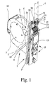
- in einer perspektivischen Ansicht den vorderen Bereich eines erfindungsgemäßen Gurtwicklers ohne Frontblende,
- Fig. 2
- in einer Ansicht von vorne den Gurtwickler gemäß Fig. 1 - a) mit Frontblende und b) ohne Frontblende, und
- Fig. 3
- in einer Ansicht von oben den Gurtwickler gemäß Fig. 1 - a) mit Frontblende und b) ohne Frontblende.
- Fig. 1
- in a perspective view of the front portion of a Gurtwicklers invention without front panel,
- Fig. 2
- in a front view of the Gurtwickler of FIG. 1 - a) with front panel and b) without front panel, and
- Fig. 3
- in a view from above the Gurtwickler of FIG. 1 - a) with front panel and b) without front panel.
Der in der Zeichnung dargestellte Gurtwickler ist bestimmt für eine Verdunkelungsvorrichtung wie einen Rolladen, eine Jalousie, eine Markise o. dgl., Der Gurtwickler ist mit einem Gehäuse 1 sowie mit einer im Gehäuse 1 befindlichen Antriebsanordnung 2 ausgestattet. Beim dem Gehäuse 1 muß es sich nicht notwendigerweise um ein vollständig geschlossenes Gehäuse 1 handeln. Beispielsweise fällt vorliegend unter den Begriff "Gehäuse" auch ein Rahmen, der die Antriebsanordnung 2 aufnimmt.The Gurtwickler shown in the drawing is intended for a darkening device such as a blind, a blind, an awning o. The like., The Gurtwickler is equipped with a
Die Antriebsanordnung 2 weist vorzugsweise eine Haspel 3 zum Aufwickeln eines Gurtbandes 4, einen elektrischen Antriebsmotor 5 sowie ein zur Haspel 3 kuppelndes Untersetzungsgetriebe 6 auf. Diese Komponenten der Antriebsanordnung 2 sind in der Zeichnung lediglich angedeutet. Hinsichtlich einer bevorzugten Ausgestaltung der Antriebsanordnung 2 darf auf das deutsche Gebrauchsmuster 297 22 936.2 der Anmelderin verwiesen werden. Der Inhalt dieses Gebrauchsmusters wird insoweit in vollem Umfange zum Gegenstand der vorliegenden Anmeldung gemacht.The drive assembly 2 preferably has a
Der Gurtwickler ist mit einer Steuerungsanordnung 7 ausgestattet, die bei der dargestellten und insoweit bevorzugten Ausgestaltung im Gehäuse 1 angeordnet ist. Es kann aber auch vorgesehen sein, daß die Steuerungsanordnung 7 am Gehäuse 1 angeordnet ist. Dies ist beispielsweise der Fall, wenn die Steuerungsanordnung 7 in mehreren Modulen aufgebaut ist, die jeweils auf das Gehäuse 1 aufsteckbar sind.The Gurtwickler is equipped with a
Die Steuerungsanordnung 7 weist ein Zeitmodul 8 auf, das als Funkuhrmodul ausgestaltet ist. In besonders bevorzugter Ausgestaltung handelt es sich bei dem Zeitmodul 8 um ein DCF-Modul. Es ist aber auch denkbar, das Zeitmodul 8 als TDF-Modul auszugestalten. Mittels des Zeitmoduls 8 läßt sich ein Zeitsignal zur Ermittlung der aktuellen Zeit über Funk empfangen. Im dargestellten Ausführungsbeispiel ist dem Zeitmodul 8 eine Antenne 9 für den Empfang des Zeitsignals zugeordnet Grundsätzlich kann die Antenne 9 auch integraler Bestandteil des Zeitmoduls 9 sein.The
Da es sich bei der Ausgestaltung des Zeitmoduls 8 als DCF-Modul oder als TDF-Modul um einen Langwellenempfänger handelt, ist die Antenne 9 vorzugsweise als Ferrit-Antenne ausgestaltet. Dies ist auch bei der dargestellten und insoweit bevorzugten Ausführungsform der Fall.Since the design of the
Wesentlich ist nun, daß die Antenne 9 des Zeitmoduls 8 über eine Haltevorrichtung 10 derart verstellbar angeordnet ist, daß ein Ausrichten der Antenne 9 zur Optimierung des Empfangs des Zeitsignals möglich ist. Dies läßt sich einer Zusammenschau der Fig. 1 und 3 entnehmen und wird im folgenden noch näher erläutert,It is essential that the
Bei der dargestellten und insoweit bevorzugten AusRhmngsform ist das Gehäuse 1 im eingebauten Zustand jedenfalls größtenteils in einer Mauerwerksausnehmung angeordnet. Gurtwickler dieser Art werden eingesetzt häufig in der Nachrüstung bei vorhandenen Verdunkelungsvorrichtungen, um vorhandene mechanische Guriwickler zu ersetzen. Der wesentliche Vorteil eines solchen Gurtwicklers mit Elektromotor besteht darin, daß er ohne weiteres in der meist genormten Mauerwerksausnehmung für den rein mechanischen Gurtwickler ersatzweise Platz findet. Der Austausch ist also sehr einfach möglich.In the illustrated and so far preferred Ausrhmngsform the
Grundsätzlich kann der Gurtwickler aber auch als Aufputz-Gerät ausgestaltet sein. Derartige Gurtwickler werden entsprechend dann eingesetzt, wenn eine Mauerwerksausnehmung nicht vorhanden ist oder, beispielsweise aus Kostengründen, nicht vorgesehen werden soll.In principle, the Gurtwickler but also be designed as a surface-mounted device. Such Gurtwickler be used accordingly when a masonry recess is not available or, for example, for reasons of cost, should not be provided.
Bei beiden oben genannten Varianten eines Gurtwicklers ist das als Funkuhrmodul ausgestaltete Zeitmodul 8, insbesondere die Antenne 9, zwangsweise in unmittelbarer Nähe zum Mauerwerk angeordnet. Insbesondere bei einem Mauerwerk mit integrierter Bewehrung führt dies zu einem Abschirmeffekt durch das Mauerwerk und im Ergebnis zu einer Behinderung beim Empfang des Zeitsignals über Funk, Unter Berücksichtigung dieser grundsätzlich bestehenden Behinderung beim Empfang des Zeitsignals ist es besonders vorteilhaft, daß die Antenne 9 bei dem vorschlagsgemäßen Gurtwickler ausgerichtet werden kann. Ohne das Ausrichten der Antenne 9 kann ein zuverlässiger Empfang des Zeitsignals nicht sichergestellt werden.In both above-mentioned variants of a Gurtwicklers designed as a radio clock
Es ist der Darstellung in Fig. 2 zu entnehmen, daß das Gehäuse 1 eine Frontblende 11 aufweist, die verschiedene Bedienungselemente 12, eine Anzeige 13 und einen Einführkanal 14 für das Gurtband 4 einfaßt. Grundsätzlich kann es auch vorgesehen sein, daß die Frontblende 11 die genannten Elemente 12, 13, 14 aufnimmt. Beispielsweise können die Bedienungselemente 12 auf der Frontblende 11 angeordnet sein.It can be seen from the illustration in Fig. 2, that the
Das Gehäuse 1 weist also jedenfalls einen Grundkörper 15 und die obige Frontblende 11 auf Es kann auch sein, daß das Gehäuse 1 aus einer Vielzahl weiterer Teilkomponenten besteht.The
Vorzugsweise ist die Antenne 9 im Gehäuse 1 angeordnet. Besonders vorteilhaft ist die Anordnung der Antenne 9 unmittelbar unter der Frontblende 11, so daß möglichst wenige konstruktive Komponenten des Gurtwicklers den Empfang des Zeitsignals stören. Bei dem dargestellten und insoweit bevorzugten Ausführungsbeispiel ist es ferner so, daß die Antenne 9 im Bereich des Einführkanals 14 für das Gurtband 4 angeordnet ist. Dies ist insofern vorteilhaft, als die Antenne 9 dann in deutlicher Entfernung von der Antriebsanordnung 2 und deren den Empfang störenden bzw. abschirmenden Komponenten entfernt ist.Preferably, the
In besonders bevorzugter Ausgestaltung ist die Antenne 9 um eine Schwenkachse 16 schwenkbar verstellbar. Der hiermit erreichbare Schwenkwinkel der Antenne 9 ist im wesentlichen abhängig von der Ausgestaltung des Gehäuses 1. Bei dem dargestellten Ausftihrungsbeispiel beträgt der Schwenkwinkel der Antenne 9 etwa 12°.In a particularly preferred embodiment, the
Insbesondere bei der Ausgestaltung der Antenne 9 als Ferrit-Antenne ist es vorzugsweise so, daß sich die Antenne 9 in Richtung einer Längsachse 17 erstreckt, wobei sich die Schwenkachse 16 der Antenne 9 vorzugsweise senkrecht zur Längsachse 17 der Antenne 9 erstreckt. Dies ist in Fig. 1 dargestellt. Es ist der Darstellung in Fig. 1 ferner zu entnehmen, daß sich die Schwenkachse 16 der Antenne 9 im eingebauten Zustand im wesentlichen in vertikaler Richtung erstreckt. Dies trägt der Tatsache Rechnung, daß es bei der Ausrichtung in erster Linie darauf ankonlmt, daß die Längsachse 17 der Antenne 9 verschiedene Orientierungen innerhalb einer horizontalen Ebene einnimmt.In particular, in the embodiment of the
Grundsätzlich kann es aber auch vorgesehen sein, daß die Antenne 9 um eine weitere Schwenkachse schwenkbar ist, wobei die beiden Schwenkachsen 16 vorzugsweise zueinander senkrecht ausgerichtet sind.In principle, it can also be provided that the
Bei der dargestellten Ausführungsform ist die Ausrichtung der Antenne 9 insofern besonders leicht durchführbar, als die Antenne 9 verstellbar ist, ohne den Gurtwickler, insbesondere das Gehäuse 9 oder die Frontblende 11 des Gehäuses 1, demontieren zu müssen. Dies zeigt beispielsweise die Darstellung gemäß Fig. 3. Das Gehäuse 1, bzw. die Frontblende 11, weist hier eine Ausnehmung 18 auf, durch die hindurch ein Zugriff zur Verstellung der Antenne 9 möglich ist.In the illustrated embodiment, the orientation of the
Im einzelnen weist die Haltevorrichtung 10 der Antenne 9 für die Verstellung der Antenne 9 ein Eingriffsprofil 19 auf, das hier als eine Art Kreuzschlitz ausgestaltet ist. Das Eingriffsprofil 19 kann auch ein einfacher Schlitz oder eine andere Formgebung aufweisen. Damit ist es möglich, die Ausrichtung, also die Verstellung der Antenne 9, mit einem einfachen Werkzeug wie mit einem Schraubendreher o. dgl. zu bewerkstelligen. Es kann aber auch vorgesehen sein, daß die Haltevorrichtung 10 mit einem Betätigungselement für die Verstellung der Antenne 9 ausgestattet ist, wodurch die Verstellung der Antenne 9 ohne Werkzeug möglich wäre.In detail, the holding
Die Haltevorrichtung 10 weist nun ein feststehendes Lagerelement 20 zur schwenkbaren Lagerung eines Halteelements 21 auf. Durch den Eingriff zwischen dem Lagerelement 20 und dem Halteelement 21 ist das Halteelement 21 um die Schwenkachse 16 schwenkbar. Dabei dient das Halteelement 21 der Aufnahme der Antenne 9, wobei die Antenne 9 im dargestellten und insoweit bevorzugten Ausführungsbeispiel über Federelemente 22 im Halteelement 21 fixiert ist. Das Halteelement 21 ist vorzugsweise in das Lagerelement 20 eingeklipst. Hierfiir ist das Halteelement 21 mit einer Reihe von federnden Haken 23 ausgestattet, die im eingebauten Zustand mit einem kreisförmigen Absatz des Lagerelements 20 in Eingriff stehen.The holding
In bevorzugter Ausgestaltung ist es so, daß das Lagerelement 20 und das Halteelement 21 über jeweils eine Eingriffsfläche miteinander in Eingriff stehen und daß die Eingriffsflächen sich im wesentlichen senkrecht zur Schwenkachse 16 des Halteelements 21 erstrecken. Um zu vermeiden, daß sich die Antenne 9 selbsttätig in ungewünschter Weise verstellt, ist es vorzugsweise vorgesehen, daß diese Eingriffsflächen jeweils angerauht sind, um die Reibung zwischen diesen beiden Komponenten zu erhöhen. Eine Alternative besteht darin, daß die beiden Eingriffsflächen zueinander korrespondierende Verzahnungen aufweisen, die wiederum dem selbsttätigen, ungewünschten Verstellen der Antenne 9 entgegenwirken.In a preferred embodiment, it is such that the bearing
Eine weitere bevorzugte Ausführungsform führt zu einem besonders komfortablen Ausrichten der Antenne 9. Hier ist es vorgesehen, daß die Steuerungsanordnung 7 die Anzeige 13 derart ansteuert, daß während des Ausrichtens der Antenne 9 über die Anzeige 13 eine Information über den jeweils aktuellen Empfangspegel des Zeitsignals sichtbar ist. Hier ist beispielsweise eine zahlenmäßige Darstellung oder eine graphische Darstellung, beispielsweise durch einen Balken mit sich in Abhängigkeit vom aktuellen Empfangspegel verändernder Länge o. dgl., denkbar.A further preferred embodiment leads to a particularly convenient alignment of the
Besonders benutzerfreundlich ist schließlich eine weitere bevorzugte Ausführungsform, bei der die Antenne 9 motorisch verstellbar ist. Die Steuerungsanordnung 7 nimmt die Ausrichtung der Antenne 9 dann automatisch vor, Hierfür weist die Steuerungsanordnung 7 einen entsprechenden Regelkreis auf. Die Antenne 9 wird über den Regelkreis so lange motorisch verstellt, bis der aktuelle Empfangspegel des Zeitsignals maximal ist.Finally, a particularly preferred embodiment in which the
Es darf noch darauf hingewiesen werden, daß die Antenne 9 über eine nicht dargestellte Verbindungsleitung mit der Steuerungsanordnung 7 im übrigen verbunden ist. Hierfür ist an der Haltevorrichtung 10 ein elektrischer Anschluß 24 vorgesehen, der über die Verbindungsleitung mit einem Anschluß 25 der Steuerungsanordnung 7 entsprechend verbunden ist.It may also be pointed out that the
Schließlich darf noch ganz allgemein darauf hingewiesen werden, daß der erfindungsgemäße Gurtwickler auch mit einer Funkfiemsteuerung für das fenragesteverte Auslösen einzelner Funktionen ausgestattet sein kann. Wenn gleichzeitig, wie oben beschrieben, der Antriebsmotor 5 als Gleichstrommotor (vorzugsweise 220 V) ausgestaltet ist, so stellen sich besondere Anforderungen an diese Funkfernsteuerung. Bei einem Gleichstrommotor entsteht nämlich bei jedem Umpolen des Kommutators ein Bürstenfeuer, das die Funkübertragung der Funkfernsteuerung stört.Finally, may also be quite generally noted that the Gurtwickler invention can also be equipped with a Funkfiemsteuerung for fenragesteverte triggering individual functions. If, at the same time, as described above, the
Die obige Störung der Funkfernsteuerung durch das Bürstenfeuer des Gleichstrommotors 5 läßt sich beispielsweise durch eine geeignete Wahl des Frequenzbereichs der Funkfernsteuerung reduzieren. Es ist aber auch möglich, die Signale der Funkfernsteuerung redundant zu kodieren, so daß die Übertragung entweder fehlerresistent wird oder daß Übertragungsfehler jedenfalls erkannt werden.The above disturbance of the radio remote control by the brush fire of the
In besonders bevorzugter Ausgestaltung ist das Funksignal über, Frequenzmodulation kodiert. Dabei handelt es sich bei der Funkfernsteuerung vorzugsweise um ein GFSK-Sende-/Empfangsgerät (Gaussian Frequency Shift Keying) mit CRC-Kodierung (Cylic Redundancy Check) und mit Manchester-Code Kollisionserkennung.In a particularly preferred embodiment, the radio signal is encoded via frequency modulation. The radio remote control is preferably a GFSK transceiver (Gaussian Frequency Shift Keying) with CRC coding (Cylic Redundancy Check) and with Manchester code collision detection.
Die obige Ausgestaltung einer Funkfernsteuerung ist auf alle Bereiche der Haustechnik, insbesondere jedoch auf den Bereich der motorischen Gurtwickler für Verdunkelungsvorrichtungen wie einen Rolladen, anwendbar.The above embodiment of a radio remote control is applicable to all areas of home automation, but in particular to the field of motor Gurtwickler for dimming devices such as a shutter.
Claims (13)
dadurch gekennzeichnet,
daß die Antenne (9) über eine Haltevorrichtung (10) derart verstellbar angeordnet ist, daß ein Ausrichten der Antenne (9) zur Optimierung des Empfangs des Zeitsignals möglich ist.Gurtwickler for a darkening device such as a shutter, with a housing (1), with a housing (1) located drive assembly (2) for motor winding a webbing (4) and with a control arrangement (7), wherein the control arrangement (7) on or in the housing (1) is arranged, wherein the control arrangement (7) has a time module (8) and wherein the time module (8) as a radio clock module, in particular as a DCF module o. The like. Is configured so that a time signal for determining the current time can be received by radio, wherein the time module (8) has an antenna (9), preferably a ferrite antenna, for receiving the time signal or the time module (8) is associated with a corresponding antenna (9),
characterized,
in that the antenna (9) is arranged adjustable by way of a holding device (10) in such a way that it is possible to align the antenna (9) in order to optimize the reception of the time signal.
Applications Claiming Priority (1)
| Application Number | Priority Date | Filing Date | Title |
|---|---|---|---|
| DE200520002747 DE202005002747U1 (en) | 2005-02-18 | 2005-02-18 | Gurtwickler for a darkening device such as a roller shutter |
Publications (3)
| Publication Number | Publication Date |
|---|---|
| EP1700996A2 true EP1700996A2 (en) | 2006-09-13 |
| EP1700996A3 EP1700996A3 (en) | 2008-10-29 |
| EP1700996B1 EP1700996B1 (en) | 2009-09-02 |
Family
ID=34639012
Family Applications (1)
| Application Number | Title | Priority Date | Filing Date |
|---|---|---|---|
| EP06002040A Not-in-force EP1700996B1 (en) | 2005-02-18 | 2006-02-01 | Tape drum for a darkening device, like a roller shutter |
Country Status (3)
| Country | Link |
|---|---|
| EP (1) | EP1700996B1 (en) |
| AT (1) | ATE441773T1 (en) |
| DE (2) | DE202005002747U1 (en) |
Cited By (5)
| Publication number | Priority date | Publication date | Assignee | Title |
|---|---|---|---|---|
| EP1985792A3 (en) * | 2007-04-25 | 2009-02-18 | ARCA Beteiligungen GmbH | Belt coiler for a roller shutter |
| WO2017054083A1 (en) * | 2015-10-02 | 2017-04-06 | Axis Labs Inc. | External motor drive system for window covering system with continuous cord loop |
| US10863846B2 (en) | 2015-10-02 | 2020-12-15 | Axis Labs Inc. | External motor drive system for window covering system with continuous cord loop |
| US11519221B2 (en) | 2014-11-06 | 2022-12-06 | Ryse Inc. | Motor drive system for window covering system with continuous cord loop |
| US11840886B2 (en) | 2021-05-12 | 2023-12-12 | Ryse Inc. | External motor drive system adjusting for creep in window covering system with continuous cord loop |
Families Citing this family (2)
| Publication number | Priority date | Publication date | Assignee | Title |
|---|---|---|---|---|
| DE202006003524U1 (en) * | 2006-03-04 | 2006-04-27 | Alfred Schellenberg Gmbh | Gurtwickler for the webbing or the like. Tension element of a darkening device, in particular a shutter or the like. |
| DE202009001375U1 (en) | 2009-02-04 | 2010-06-24 | Arca Beteiligungen Gmbh | Drive for the motorized adjustment of a darkening device such as a roller shutter or the like. |
Citations (2)
| Publication number | Priority date | Publication date | Assignee | Title |
|---|---|---|---|---|
| DE20001483U1 (en) | 2000-01-28 | 2000-08-17 | Rademacher, Wilhelm, 46414 Rhede | Remote control device and blackout system |
| DE102004012354A1 (en) | 2003-03-11 | 2004-09-30 | ECG Elektrocomponent Gründau GmbH | A roller blind winding unit has separable operating and driving parts for the safety of unskilled users |
-
2005
- 2005-02-18 DE DE200520002747 patent/DE202005002747U1/en not_active Expired - Lifetime
-
2006
- 2006-02-01 DE DE502006004699T patent/DE502006004699D1/en active Active
- 2006-02-01 EP EP06002040A patent/EP1700996B1/en not_active Not-in-force
- 2006-02-01 AT AT06002040T patent/ATE441773T1/en active
Patent Citations (2)
| Publication number | Priority date | Publication date | Assignee | Title |
|---|---|---|---|---|
| DE20001483U1 (en) | 2000-01-28 | 2000-08-17 | Rademacher, Wilhelm, 46414 Rhede | Remote control device and blackout system |
| DE102004012354A1 (en) | 2003-03-11 | 2004-09-30 | ECG Elektrocomponent Gründau GmbH | A roller blind winding unit has separable operating and driving parts for the safety of unskilled users |
Cited By (10)
| Publication number | Priority date | Publication date | Assignee | Title |
|---|---|---|---|---|
| EP1985792A3 (en) * | 2007-04-25 | 2009-02-18 | ARCA Beteiligungen GmbH | Belt coiler for a roller shutter |
| US11519221B2 (en) | 2014-11-06 | 2022-12-06 | Ryse Inc. | Motor drive system for window covering system with continuous cord loop |
| US12098595B2 (en) | 2014-11-06 | 2024-09-24 | Ryse Inc. | Motor drive system for window covering system with continuous cord loop |
| WO2017054083A1 (en) * | 2015-10-02 | 2017-04-06 | Axis Labs Inc. | External motor drive system for window covering system with continuous cord loop |
| US10104997B2 (en) | 2015-10-02 | 2018-10-23 | Axis Labs Inc. | External motor drive system for window covering system with continuous cord loop |
| US10863846B2 (en) | 2015-10-02 | 2020-12-15 | Axis Labs Inc. | External motor drive system for window covering system with continuous cord loop |
| US11178992B2 (en) | 2015-10-02 | 2021-11-23 | Ryse Inc. | External motor drive system for window covering system with continuous cord loop |
| US11272802B2 (en) | 2015-10-02 | 2022-03-15 | Ryse Inc. | External motor drive system for window covering system with continuous cord loop |
| US11583126B2 (en) | 2015-10-02 | 2023-02-21 | Ryse Inc. | External motor drive system for window covering system with continuous cord loop |
| US11840886B2 (en) | 2021-05-12 | 2023-12-12 | Ryse Inc. | External motor drive system adjusting for creep in window covering system with continuous cord loop |
Also Published As
| Publication number | Publication date |
|---|---|
| EP1700996A3 (en) | 2008-10-29 |
| DE502006004699D1 (en) | 2009-10-15 |
| EP1700996B1 (en) | 2009-09-02 |
| DE202005002747U1 (en) | 2005-06-02 |
| ATE441773T1 (en) | 2009-09-15 |
Similar Documents
| Publication | Publication Date | Title |
|---|---|---|
| EP1700996B1 (en) | Tape drum for a darkening device, like a roller shutter | |
| DE102005061724B4 (en) | Drive for actuating a movable wing, in particular a door or a window | |
| EP1766743B1 (en) | Bus bar system with assembly unit consisting of a base plate and fixing items | |
| EP1455038B1 (en) | Locking system, in particular door lock, window lock or similar | |
| EP1856355B1 (en) | Window or door | |
| DE10346654B3 (en) | Handle for window or door has radio signal contact integrated into interior space with position detection unit, electronics with position evaluation, transmission module, antenna and power supply unit | |
| WO2016019950A1 (en) | Adapter for the contacting of a power switch on a busbar system | |
| EP1091079A2 (en) | Control system for motor-driven driving units of darkening or shading systems | |
| EP1132560B1 (en) | Hinge and method of height adjustment of a hinge | |
| DE102004012354B4 (en) | Electric belt winder | |
| EP1574656A2 (en) | Driving device for a gate | |
| DE102007014170A1 (en) | Optoelectronic sensor arrangement comprises housing, in which opto-transmitter and opto-receiver are arranged, where housing is arranged in frame profile | |
| DE9403746U1 (en) | Device for opening and closing gates | |
| EP0168714B1 (en) | Fast mounting of a casing of an electrical installation apparatus on a mounting rail | |
| EP0529316A1 (en) | Room temperature control device | |
| EP1837467A2 (en) | Locking system for a door or similar | |
| DE3742425A1 (en) | Method and arrangement for detecting the functional states in a television set | |
| EP1725729B1 (en) | Suspension system for sliding door | |
| EP3483374B1 (en) | Guiding rail for guiding a door wing between an open position and a closed position | |
| DE19648147C1 (en) | Motorized tilt opening device for windows or doors | |
| DE3037405A1 (en) | LV terminal and switch contact strip - has insulating block clamp terminals with contact spring extensions into female housing | |
| EP2216491B1 (en) | Drive for the motorised adjustment of a darkening device such as a roller blind or similar | |
| EP1985792A2 (en) | Belt coiler for a roller shutter | |
| EP2151909A2 (en) | Drive component for the motorised adjustment of an adjustment element in a motor vehicle | |
| EP1449988A2 (en) | Catch module for window- and door-fittings |
Legal Events
| Date | Code | Title | Description |
|---|---|---|---|
| PUAI | Public reference made under article 153(3) epc to a published international application that has entered the european phase |
Free format text: ORIGINAL CODE: 0009012 |
|
| AK | Designated contracting states |
Kind code of ref document: A2 Designated state(s): AT BE BG CH CY CZ DE DK EE ES FI FR GB GR HU IE IS IT LI LT LU LV MC NL PL PT RO SE SI SK TR |
|
| AX | Request for extension of the european patent |
Extension state: AL BA HR MK YU |
|
| RAP1 | Party data changed (applicant data changed or rights of an application transferred) |
Owner name: ARCA BETEILIGUNGEN GMBH |
|
| RIN1 | Information on inventor provided before grant (corrected) |
Inventor name: RADEMACHER, WILHELM |
|
| PUAL | Search report despatched |
Free format text: ORIGINAL CODE: 0009013 |
|
| AK | Designated contracting states |
Kind code of ref document: A3 Designated state(s): AT BE BG CH CY CZ DE DK EE ES FI FR GB GR HU IE IS IT LI LT LU LV MC NL PL PT RO SE SI SK TR |
|
| AX | Request for extension of the european patent |
Extension state: AL BA HR MK YU |
|
| 17P | Request for examination filed |
Effective date: 20081126 |
|
| GRAP | Despatch of communication of intention to grant a patent |
Free format text: ORIGINAL CODE: EPIDOSNIGR1 |
|
| AKX | Designation fees paid |
Designated state(s): AT BE BG CH CY CZ DE DK EE ES FI FR GB GR HU IE IS IT LI LT LU LV MC NL PL PT RO SE SI SK TR |
|
| GRAS | Grant fee paid |
Free format text: ORIGINAL CODE: EPIDOSNIGR3 |
|
| GRAA | (expected) grant |
Free format text: ORIGINAL CODE: 0009210 |
|
| AK | Designated contracting states |
Kind code of ref document: B1 Designated state(s): AT BE BG CH CY CZ DE DK EE ES FI FR GB GR HU IE IS IT LI LT LU LV MC NL PL PT RO SE SI SK TR |
|
| REG | Reference to a national code |
Ref country code: CH Ref legal event code: EP |
|
| REG | Reference to a national code |
Ref country code: IE Ref legal event code: FG4D Free format text: LANGUAGE OF EP DOCUMENT: GERMAN |
|
| REF | Corresponds to: |
Ref document number: 502006004699 Country of ref document: DE Date of ref document: 20091015 Kind code of ref document: P |
|
| PG25 | Lapsed in a contracting state [announced via postgrant information from national office to epo] |
Ref country code: LT Free format text: LAPSE BECAUSE OF FAILURE TO SUBMIT A TRANSLATION OF THE DESCRIPTION OR TO PAY THE FEE WITHIN THE PRESCRIBED TIME-LIMIT Effective date: 20090902 Ref country code: FI Free format text: LAPSE BECAUSE OF FAILURE TO SUBMIT A TRANSLATION OF THE DESCRIPTION OR TO PAY THE FEE WITHIN THE PRESCRIBED TIME-LIMIT Effective date: 20090902 Ref country code: SE Free format text: LAPSE BECAUSE OF FAILURE TO SUBMIT A TRANSLATION OF THE DESCRIPTION OR TO PAY THE FEE WITHIN THE PRESCRIBED TIME-LIMIT Effective date: 20090902 |
|
| NLV1 | Nl: lapsed or annulled due to failure to fulfill the requirements of art. 29p and 29m of the patents act | ||
| LTIE | Lt: invalidation of european patent or patent extension |
Effective date: 20090902 |
|
| PG25 | Lapsed in a contracting state [announced via postgrant information from national office to epo] |
Ref country code: SI Free format text: LAPSE BECAUSE OF FAILURE TO SUBMIT A TRANSLATION OF THE DESCRIPTION OR TO PAY THE FEE WITHIN THE PRESCRIBED TIME-LIMIT Effective date: 20090902 Ref country code: PL Free format text: LAPSE BECAUSE OF FAILURE TO SUBMIT A TRANSLATION OF THE DESCRIPTION OR TO PAY THE FEE WITHIN THE PRESCRIBED TIME-LIMIT Effective date: 20090902 Ref country code: NL Free format text: LAPSE BECAUSE OF FAILURE TO SUBMIT A TRANSLATION OF THE DESCRIPTION OR TO PAY THE FEE WITHIN THE PRESCRIBED TIME-LIMIT Effective date: 20090902 Ref country code: LV Free format text: LAPSE BECAUSE OF FAILURE TO SUBMIT A TRANSLATION OF THE DESCRIPTION OR TO PAY THE FEE WITHIN THE PRESCRIBED TIME-LIMIT Effective date: 20090902 |
|
| PG25 | Lapsed in a contracting state [announced via postgrant information from national office to epo] |
Ref country code: CY Free format text: LAPSE BECAUSE OF FAILURE TO SUBMIT A TRANSLATION OF THE DESCRIPTION OR TO PAY THE FEE WITHIN THE PRESCRIBED TIME-LIMIT Effective date: 20090902 |
|
| REG | Reference to a national code |
Ref country code: IE Ref legal event code: FD4D |
|
| PG25 | Lapsed in a contracting state [announced via postgrant information from national office to epo] |
Ref country code: IS Free format text: LAPSE BECAUSE OF FAILURE TO SUBMIT A TRANSLATION OF THE DESCRIPTION OR TO PAY THE FEE WITHIN THE PRESCRIBED TIME-LIMIT Effective date: 20100102 Ref country code: RO Free format text: LAPSE BECAUSE OF FAILURE TO SUBMIT A TRANSLATION OF THE DESCRIPTION OR TO PAY THE FEE WITHIN THE PRESCRIBED TIME-LIMIT Effective date: 20090902 Ref country code: IE Free format text: LAPSE BECAUSE OF FAILURE TO SUBMIT A TRANSLATION OF THE DESCRIPTION OR TO PAY THE FEE WITHIN THE PRESCRIBED TIME-LIMIT Effective date: 20090902 Ref country code: CZ Free format text: LAPSE BECAUSE OF FAILURE TO SUBMIT A TRANSLATION OF THE DESCRIPTION OR TO PAY THE FEE WITHIN THE PRESCRIBED TIME-LIMIT Effective date: 20090902 Ref country code: PT Free format text: LAPSE BECAUSE OF FAILURE TO SUBMIT A TRANSLATION OF THE DESCRIPTION OR TO PAY THE FEE WITHIN THE PRESCRIBED TIME-LIMIT Effective date: 20100104 Ref country code: ES Free format text: LAPSE BECAUSE OF FAILURE TO SUBMIT A TRANSLATION OF THE DESCRIPTION OR TO PAY THE FEE WITHIN THE PRESCRIBED TIME-LIMIT Effective date: 20091213 Ref country code: EE Free format text: LAPSE BECAUSE OF FAILURE TO SUBMIT A TRANSLATION OF THE DESCRIPTION OR TO PAY THE FEE WITHIN THE PRESCRIBED TIME-LIMIT Effective date: 20090902 |
|
| PG25 | Lapsed in a contracting state [announced via postgrant information from national office to epo] |
Ref country code: SK Free format text: LAPSE BECAUSE OF FAILURE TO SUBMIT A TRANSLATION OF THE DESCRIPTION OR TO PAY THE FEE WITHIN THE PRESCRIBED TIME-LIMIT Effective date: 20090902 |
|
| PLBE | No opposition filed within time limit |
Free format text: ORIGINAL CODE: 0009261 |
|
| STAA | Information on the status of an ep patent application or granted ep patent |
Free format text: STATUS: NO OPPOSITION FILED WITHIN TIME LIMIT |
|
| PG25 | Lapsed in a contracting state [announced via postgrant information from national office to epo] |
Ref country code: DK Free format text: LAPSE BECAUSE OF FAILURE TO SUBMIT A TRANSLATION OF THE DESCRIPTION OR TO PAY THE FEE WITHIN THE PRESCRIBED TIME-LIMIT Effective date: 20090902 |
|
| 26N | No opposition filed |
Effective date: 20100603 |
|
| REG | Reference to a national code |
Ref country code: CH Ref legal event code: PL |
|
| GBPC | Gb: european patent ceased through non-payment of renewal fee |
Effective date: 20100201 |
|
| PG25 | Lapsed in a contracting state [announced via postgrant information from national office to epo] |
Ref country code: LI Free format text: LAPSE BECAUSE OF NON-PAYMENT OF DUE FEES Effective date: 20100228 Ref country code: CH Free format text: LAPSE BECAUSE OF NON-PAYMENT OF DUE FEES Effective date: 20100228 Ref country code: MC Free format text: LAPSE BECAUSE OF NON-PAYMENT OF DUE FEES Effective date: 20100301 Ref country code: GR Free format text: LAPSE BECAUSE OF FAILURE TO SUBMIT A TRANSLATION OF THE DESCRIPTION OR TO PAY THE FEE WITHIN THE PRESCRIBED TIME-LIMIT Effective date: 20091203 |
|
| PG25 | Lapsed in a contracting state [announced via postgrant information from national office to epo] |
Ref country code: GB Free format text: LAPSE BECAUSE OF NON-PAYMENT OF DUE FEES Effective date: 20100201 Ref country code: IT Free format text: LAPSE BECAUSE OF FAILURE TO SUBMIT A TRANSLATION OF THE DESCRIPTION OR TO PAY THE FEE WITHIN THE PRESCRIBED TIME-LIMIT Effective date: 20090902 |
|
| PGFP | Annual fee paid to national office [announced via postgrant information from national office to epo] |
Ref country code: FR Payment date: 20120227 Year of fee payment: 7 |
|
| PGFP | Annual fee paid to national office [announced via postgrant information from national office to epo] |
Ref country code: DE Payment date: 20120102 Year of fee payment: 7 |
|
| PGFP | Annual fee paid to national office [announced via postgrant information from national office to epo] |
Ref country code: BE Payment date: 20120329 Year of fee payment: 7 |
|
| PG25 | Lapsed in a contracting state [announced via postgrant information from national office to epo] |
Ref country code: BG Free format text: LAPSE BECAUSE OF FAILURE TO SUBMIT A TRANSLATION OF THE DESCRIPTION OR TO PAY THE FEE WITHIN THE PRESCRIBED TIME-LIMIT Effective date: 20090902 Ref country code: HU Free format text: LAPSE BECAUSE OF FAILURE TO SUBMIT A TRANSLATION OF THE DESCRIPTION OR TO PAY THE FEE WITHIN THE PRESCRIBED TIME-LIMIT Effective date: 20100303 Ref country code: LU Free format text: LAPSE BECAUSE OF NON-PAYMENT OF DUE FEES Effective date: 20100201 |
|
| PG25 | Lapsed in a contracting state [announced via postgrant information from national office to epo] |
Ref country code: TR Free format text: LAPSE BECAUSE OF FAILURE TO SUBMIT A TRANSLATION OF THE DESCRIPTION OR TO PAY THE FEE WITHIN THE PRESCRIBED TIME-LIMIT Effective date: 20090902 |
|
| REG | Reference to a national code |
Ref country code: AT Ref legal event code: MM01 Ref document number: 441773 Country of ref document: AT Kind code of ref document: T Effective date: 20110201 |
|
| PG25 | Lapsed in a contracting state [announced via postgrant information from national office to epo] |
Ref country code: AT Free format text: LAPSE BECAUSE OF NON-PAYMENT OF DUE FEES Effective date: 20110201 |
|
| BERE | Be: lapsed |
Owner name: ARCA BETEILIGUNGEN G.M.B.H. Effective date: 20130228 |
|
| REG | Reference to a national code |
Ref country code: FR Ref legal event code: ST Effective date: 20131031 |
|
| REG | Reference to a national code |
Ref country code: DE Ref legal event code: R119 Ref document number: 502006004699 Country of ref document: DE Effective date: 20130903 |
|
| PG25 | Lapsed in a contracting state [announced via postgrant information from national office to epo] |
Ref country code: FR Free format text: LAPSE BECAUSE OF NON-PAYMENT OF DUE FEES Effective date: 20130228 Ref country code: DE Free format text: LAPSE BECAUSE OF NON-PAYMENT OF DUE FEES Effective date: 20130903 Ref country code: BE Free format text: LAPSE BECAUSE OF NON-PAYMENT OF DUE FEES Effective date: 20130228 |