EP1700208B1 - Appareil et procédé permettant d'éviter des instructions de contrôle du mode virgule flottante dans la conversion d'un nombre en virgule flottante en nombre entier - Google Patents
Appareil et procédé permettant d'éviter des instructions de contrôle du mode virgule flottante dans la conversion d'un nombre en virgule flottante en nombre entier Download PDFInfo
- Publication number
- EP1700208B1 EP1700208B1 EP04814077A EP04814077A EP1700208B1 EP 1700208 B1 EP1700208 B1 EP 1700208B1 EP 04814077 A EP04814077 A EP 04814077A EP 04814077 A EP04814077 A EP 04814077A EP 1700208 B1 EP1700208 B1 EP 1700208B1
- Authority
- EP
- European Patent Office
- Prior art keywords
- instructions
- floating point
- rounding
- point number
- sequence
- Prior art date
- Legal status (The legal status is an assumption and is not a legal conclusion. Google has not performed a legal analysis and makes no representation as to the accuracy of the status listed.)
- Not-in-force
Links
Images


Classifications
-
- H—ELECTRICITY
- H03—ELECTRONIC CIRCUITRY
- H03M—CODING; DECODING; CODE CONVERSION IN GENERAL
- H03M7/00—Conversion of a code where information is represented by a given sequence or number of digits to a code where the same, similar or subset of information is represented by a different sequence or number of digits
- H03M7/14—Conversion to or from non-weighted codes
- H03M7/24—Conversion to or from floating-point codes
-
- G—PHYSICS
- G06—COMPUTING; CALCULATING OR COUNTING
- G06F—ELECTRIC DIGITAL DATA PROCESSING
- G06F8/00—Arrangements for software engineering
- G06F8/40—Transformation of program code
- G06F8/52—Binary to binary
Definitions
- ANSI/IEEE standard 754-1985 for binary floating-point arithmetic defines four rounding modes to affect all arithmetic operations except comparison and remainder: round to nearest, round toward negative infinity, round toward positive infinity, and round to zero.
- the processing unit prior to execution of an instruction to convert a floating point number to an integer using a specific rounding mode, the processing unit needs to be set to that rounding mode. This is achieved by reading and storing the current rounding mode, setting the processor architecture to the desired rounding mode, performing the conversion and setting processor architecture to the stored rounding mode.
- the instructions of setting the desired rounding mode and setting the stored rounding mode are examples of floating point control instructions.
- a binary translation module may translate the source binary code into a target binary code associated with the second processor architecture.
- the results produced by executing the target binary code on a processor that complies with the target architecture are substantially the same as those produced by executing the source binary code on a processor that complies with the source architecture.
- US2002/0032718 discloses an apparatus for converting instructions for a source computer architecture into instructions for a target computer architecture
- the disclosed apparatus includes a memory device operable to store a stream of instructions for a source computer architecture; and a processor operable to process a stream of instructions stored in the memory device.
- the apparatus is such to generate a stream of instructions for a target computer architecture such that the stream of instructions when executed by a processor which complies with the target computer architecture generates the same results as occur when the original stream of instructions for said source computer architecture are executed by a processor which complies with said source computer architecture.
- US2002087609 discloses a system and method for rounding real numbers.
- the system includes a rounding apparatus to accept an input value that is a real number represented in floating-point format, and to perform a rounding operation on the input value to generate an output value that is an integer represented in floating-point format.
- the system also includes a memory to store a computer program that utilizes the rounding apparatus.
- the system further includes a central processing unit (CPU) to execute the computer program. The CPU is cooperatively connected to the rounding apparatus and the memory.
- CPU central processing unit
- US6535898 discloses a processor representation of a floating-point data item which is converted to a representation of a truncated integer item, without changing the rounding mode of a processor.
- the floating-point item When the current rounding mode is unknown, the floating-point item is converted to an integer representation in whatever mode the processor happens to be in.
- One of multiple correction values is applied, in response to the sign of the original data, a difference between the integer and the original data, and whether the item is an integer.
- the processor produces two integer representations, and selects one or the other of them as an output integer data item, in response to the sign of the original item and the relative sizes of the two representations.
- Intel Corporation: “Intel Architecture Optimization - Reference Manual", February 1999, retrieved from the internet URL: http://www.intel.co.jp/design/pentiumii/manuals/24512701.pdf discloses overviews of the architectures of the Pentium II and Pentium III processor.; the code development techniques to utilize the architecture of Pentium II and Pentium III processors as well as general strategies of efficient memory utilization; the following coding methodologies: assembly, inlined-assembly, intrinsics, vector classes, auto-vectorization, and libraries; strategies for altering data layout and restructuring algorithms for SIMD-style coding; optimization rules and techniques for high-performance integer and MMXTM technology applications; rules and optimization techniques, and provides code examples specific to floating-point code, including SIMD-floating point code for Streaming SIMD Extensions; the memory hierarchy of Pentium II and Pentium III processor Architectures, and how to best use it; the prefetch instruction and cache control management instructions for Streaming SIMD Extensions; application performance tools: VTune analyze
- an apparatus for converting instructions for a source computer architecture into instructions for a target computer architecture in accordance with claim 9.
- FIG. 1 shows a binary-code translation module according to some embodiments of the invention
- FIG. 2 is a flowchart illustration of an exemplary method to be implemented in a binary code translation module for translating a portion of a source binary code to a portion of a target binary code, according to some embodiments of the invention
- FIGS. 3 , 4 , 5A and 5B are flowchart illustrations of exemplary instruction sequences to be generated by a binary code translation module, according to some embodiments of the invention.
- FIG. 6 is a block diagram of an exemplary apparatus according to some embodiments of the invention to store and execute target binary code
- FIG. 7 is a block diagram of an exemplary apparatus according to some embodiments of the invention to translate source binary code to target binary code and to store and execute the target binary code;
- FIG. 8 is a block diagram of yet another exemplary apparatus according to some embodiments of the invention to translate source binary code to target binary code.
- An algorithm is here, and generally, considered to be a self-consistent sequence of acts or operations leading to a desired result. These include physical manipulations of physical quantities. Usually, though not necessarily, these quantities take the form of electrical or magnetic signals capable of being stored, transferred, combined, compared, and otherwise manipulated. It has proven convenient at times, principally for reasons of common usage, to refer to these signals as bits, values, elements, symbols, characters, terms, numbers or the like. It should be understood, however, that all of these and similar terms are to be associated with the appropriate physical quantities and are merely convenient labels applied to these quantities.
- Embodiments of the present invention may include apparatuses for performing the operations herein.
- This apparatus may be specially constructed for the desired purposes, or it may comprise a general purpose computer selectively activated or reconfigured by a computer program stored in the computer.
- a computer program may be stored in a computer readable storage medium, such as, but is not limited to, any type of disk including floppy disks, optical disks, CD-ROMs, magnetic-optical disks, read-only memories (ROMs), random access memories (RAMs), electrically programmable read-only memories (EPROMs), electrically erasable and programmable read only memories (EEPROMs), magnetic or optical cards, or any other type of media suitable for storing electronic instructions, and capable of being coupled to a computer system bus.
- Fig. 1 shows a binary-code translation module 2 according to some embodiments of the invention.
- Binary-code translation module 2 may receive as input a binary code ("source binary code”) associated with a first processor architecture having a first set of instructions (“source architecture”), and may output a binary code (“target binary code”) associated with a second processor architecture having a second set of instructions (“target architecture”)-
- source binary code binary code
- target binary code binary code associated with a second processor architecture having a second set of instructions
- the results produced by executing the target binary code on a processor that complies with the target architecture may be substantially the same as those produced by executing the source binary code on a processor that complies with the source architecture.
- the instructions sets of both the source and target architectures may comply with ANSI/IEEE standard 754-1985 for binary floating-point arithmetic and may support conversion of floating point numbers to integer numbers using at least the four rounding modes defined in ANSI/IEEE standard 754-1985 to affect all arithmetic operations except comparison and remainder: round to nearest, round toward negative infinity, round toward positive infinity, and round to zero.
- a floating point number is implemented in a computer as a representation of a floating point number.
- an integer number is implemented in a computer as a representation of a integer number. For example, 32 bits or 64 bits may be used to physically represent a floating point number, and 16 bits or 32 bits may be used to physically represent an integer number.
- the source architecture Prior to execution of an instruction to convert a floating point number to an integer using a specific rounding mode in the source architecture, the source architecture may need to be set to that rounding mode by, for example, a floating point control instruction.
- the source architecture may need to execute the following exemplary sequence of four instructions (referred to as sequence "A"), :
- instruction a ⁇ is followed by instruction b. ⁇
- instruction b. ⁇ is followed by instruction c. ⁇
- instruction c. ⁇ is followed by instruction d. ⁇ .
- followed by means that a first instruction is executed after a second instruction, and other instructions may or may not be intervening between the second and the first instructions.
- the target architecture may need to be set to that rounding mode by, for example, a floating point control instruction.
- the instruction set of the target architecture comprises an instruction to round floating point numbers to floating point numbers using round to zero rounding mode, regardless of the rounding mode setting of the target architecture ("round to zero forced mode instruction"), it may be possible to avoid the use of a floating point control instruction to set the rounding mode in the target architecture.
- binary-code translation module 2 may use the round to zero forced mode instruction of the target architecture to translate a source binary code portion comprising a sequence "A" into a target binary code portion that does not include a floating point control instruction.
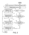
- FIG. 2 is a flowchart illustration according to some embodiments of the invention of an exemplary method to be implemented in a binary code translation module for translating a portion of a source binary code to a portion of a target binary code.
- FIGS- 3, 4, 5A and 5B are flowchart illustrations of exemplary instruction sequences to be generated by a binary code translation module, according to some embodiments of the invention.
- binary code translation module 2 may identify a sequence similar to exemplary sequence "A" in the source binary code (-10-) and may then identify the new rounding mode (-11-).
- binary code translation module 2 may translate source binary code sequence "A” into an equivalent target binary code sequence "A" (-14-) having floating point control instructions for changing rounding modes.
- binary code translation module 2 may translate source binary code sequence "A” into a target binary code sequence "B" (-18-), described in FIG. 3 .
- binary code translation module 2 may translate source binary code sequence "A” into a target binary code sequence "C” (-22-), described in FIG. 4 .
- binary code translation module 2 may translate source binary code sequence "A” into a target binary code sequence "D" (-24-), described in FIGs. 5A and 5B .
- FIG. 3 is a flowchart illustration of the method of an exemplary target binary code sequence "B", according to some embodiments of the invention. It should be noted that the method of FIG. 3 may be executed by a target processor after checking that the floating point data is a suitable floating point number. For example, floating point data defined by ANSI/IEEE standard 754-1985 for binary floating-point arithmetic as "Infinite” or as "Quiet not a number" (QNaN) may not be suitable.
- a first floating point number is generated by rounding an initial floating point number using a round to zero forced mode instruction (-30-). If the first floating point number is positive (-32-) or if its value is equal to the value of the initial floating point number (-34-), then a result integer number is generated by converting the representation of the first floating point number to an integer representation (-36-). Otherwise, a second floating point number is generated by subtracting one from the first floating point number (-38-), and the result integer number is generated by converting the representation of the second floating point number to an integer representation (-39-).
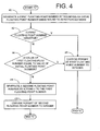
- FIG. 4 is a flowchart illustration of the method of an exemplary target binary code sequence "C", according to some embodiments of the invention. It should be noted that the method of FIG. 3 may be executed by a target processor after checking that the floating point data is a suitable floating point number.
- a first floating point number is generated by rounding an initial floating point number using a round to zero forced mode instruction (-40-). If the first floating point number is negative (-42-) or if its value is equal to the value of the initial floating point number (-44-), then a result integer number is generated by converting the representation of the first floating point number to an integer representation (-46-). Otherwise, a second floating point number is generated by adding one to the first floating point number (-48-), and the result integer number is generated by converting the representation of the second floating point number to an integer representation (-49-).
- FIG. 5A is a flowchart illustration of the operation of an exemplary target binary code sequence "D", according to some embodiments of the invention.
- the floating point number is converted to an integer number using the round to zero mode (-50-).
- FIG. 5B is a flowchart illustration of the operation of another exemplary target binary code sequence "D", according to some embodiments of the invention.
- the initial floating point number is converted to a first floating point number using the round to zero forced mode instruction (-52-).
- the result integer number is generated by converting the representation of the first floating point number to an integer representation (-54-).
- FIG. 6 is a block diagram of an exemplary apparatus 60 according to some embodiments of the invention.
- Apparatus 60 may comprise a processor 62 and a memory 64 coupled to processor 62.
- Memory 64 may store a target binary code 66 generated by a binary-code translation module (not shown) using the method described in FIGS. 2 - 5 .
- Target binary code 66 complies with the architecture of processor 62.
- Processor 62 may execute target binary code 66.
- FIG. 7 is a block diagram of an exemplary apparatus 70 according to some embodiments of the invention.
- Apparatus 70 may comprise a processor 72 and a memory 74 coupled to processor 72.
- Memory 74 may store a source binary code 76 that does not comply with the architecture of processor 72, and a binary code translation module 78, suitable to translate source binary code 76 to a target binary code that complies with the architecture of processor 72.
- Processor 72 may execute binary code translation module 78 to translate source binary code 76 into a target binary code 80.
- Target binary code 80 may then be stored in memory 74 and may be executed by processor 72.
- source binary code 76, binary-code translation module 78 and target binary code 80 may be stored in separate memories that are coupled to processor 72.
- FIG. 8 is a block diagram of an exemplary apparatus according to some embodiments of the invention to translate source binary code to target binary code.
- Apparatus 90 may comprise a processor 92 and a memory 94 coupled to processor 92.
- Memory 94 may store a binary code translation module 96.
- Binary code translation module 96 may be able to translate a source binary code associated with a source processor architecture into a target binary code associated with a target processor architecture.
- the architecture of processor 92 may, or may not, comply with the source architecture and may, or may not, comply with the target architecture.
- Processor 92 may receive source binary code, may execute binary code translation module 96, and may output target binary code.
- a non-exhaustive list of examples for apparatuses 60, 70 and 90 includes a desktop personal computer, a work station, a server computer, a laptop computer, a notebook computer, a hand-held computer, a personal digital assistant (PDA), a mobile telephone, and the like.
- a desktop personal computer a work station
- a server computer a laptop computer
- a notebook computer a hand-held computer
- PDA personal digital assistant
- Processors 62, 72 and 92 includes a central processing unit (CPU), a digital signal processor (DSP), a reduced instruction set computer (RISC), a complex instructions set computer (CISC) and the like. Moreover, processors 62, 72 and 92 may be part of an application specific integrated circuit (ASIC) or may be a part of an application specific standard product (ASSP).
- CPU central processing unit
- DSP digital signal processor
- RISC reduced instruction set computer
- CISC complex instructions set computer
- ASIC application specific integrated circuit
- ASSP application specific standard product
- Memories 64, 74 and 94 may be fixed in or removable from apparatuses 60, 70 and 90, respectively,
- a non-exhaustive list of examples for memories 64, 74 and 94 includes any combination of the followings: semiconductor devices, such as synchronous dynamic random access Memory (SDRAM) devices, RAMBUS dynamic random access memory (RDRAM) devices, double data rate (DDR) memory devices, static random access memory (SRAM), flash memory devices, electrically erasable programmable read only memory devices (EEPROM), non-volatile random access memory devices (NVRAM), universal serial bus (USB) removable memory, and the like, optical devices, such as compact disk read only memory (CD ROM), and the like, and magnetic devices, such as a hard disk, a floppy disk, a magnetic tape, and the like.
- SDRAM synchronous dynamic random access Memory
- RDRAM RAMBUS dynamic random access memory
- DDR double data rate
- SRAM static random access memory
- flash memory devices electrically erasable programmable read only memory devices
Claims (15)
- Procédé mis en oeuvre par ordinateur destiné à convertir des instructions pour une architecture d'ordinateur source (76) en des instructions pour une architecture d'ordinateur cible (80), le procédé comprenant le fait :de recevoir une séquence d'instructions pour ladite architecture d'ordinateur source (76) ;de traiter la séquence reçue (76) ; etde générer une séquence d'instructions (80) pour ladite architecture d'ordinateur cible où ladite séquence d'instructions (80) pour ladite architecture d'ordinateur cible lorsqu'elle est exécutée par un processeur qui est en conformité avec ladite architecture d'ordinateur cible génère les mêmes résultats que l'on obtiendrait lorsque ladite séquence d'instructions (76) pour ladite architecture d'ordinateur source est exécutée par un processeur qui est en conformité avec ladite architecture d'ordinateur source, caractérisé en ce que :le fait de traiter ladite séquence d'instructions (76) reçue comporte le fait d'identifier des séquences (10) d'instructions comprenant : une instruction destinée à sauvegarder un premier mode d'arrondi, suivie par une instruction destinée à régler un deuxième mode d'arrondi, suivie par une instruction destinée à générer un nombre entier en arrondissant un nombre en virgule flottante selon ledit deuxième mode d'arrondi, suivie par une instruction destinée à régler ledit premier mode d'arrondissement ; etle fait de générer une séquence d'instructions pour lesdites séquences identifiées comprend le fait de générer (14; 18; 22; 24) des séquences d'instructions (80) pour ladite architecture d'ordinateur cible qui aboutissent à la génération d'un nombre arrondi selon le deuxième mode d'arrondi identifié, sans instructions pour sauvegarder des données identifiant ledit premier mode d'arrondi, où le mode d'arrondi réglé après exécution d'une opération d'arrondi comprend un mode d'arrondi vers zéro,où un ensemble d'instructions de l'architecture cible comprend une instruction destinée à arrondir des nombres en virgule flottante en nombres en virgule flottante en utilisant le mode d'arrondi vers zéro, indépendamment du réglage du mode d'arrondi de l'architecture cible, appelée instruction de mode d'arrondi forcé vers zéro.
- Procédé selon la revendication 1 où le fait de générer une séquence d'instructions (80) pour lesdites séquences identifiées comprend le fait de générer (24), si ledit deuxième mode d'arrondis comprend un arrondi vers zéro, une instruction pour arrondir un nombre en virgule flottante selon un mode sélectionné du groupe constitué d'un mode d'arrondi vers zéro et d'un mode d'arrondi forcé vers zéro sans instructions pour sauvegarder, régler ou réinitialiser un mode d'arrondi.
- Procédé selon la revendication 1 ou 2, où le fait de générer une séquence d'instructions (80) pour lesdites séquences identifiées comprend le fait de générer, si ledit deuxième mode d'arrondi comprend un arrondi vers +∞ ou vers -∞, des instructions (18; 22) pour arrondir un nombre en virgule flottante selon un mode d'arrondi forcé vers zéro sans instructions pour sauvegarder, régler ou réinitialiser un mode d'arrondi forcé vers zéro en même temps que des instructions additionnelles destinées à traiter un nombre en virgule flottante arrondi vers zéro afin d'obtenir un entier équivalent à l'arrondi en utilisant le deuxième mode d'arrondi identifié dans la séquence d'instructions identifiée.
- Procédé selon la revendication 3, où si ledit deuxième mode d'arrondi comprend le fait d'arrondir vers +∞, lesdites instructions additionnelles destinées à traiter un nombre en virgule flottante arrondi vers zéro comprennent des instructions destinées :à déterminer si un nombre en virgule flottante arrondi généré est positif et si un nombre en virgule flottante arrondi généré est positif et que le nombre en virgule flottante généré n'est pas égal au nombre en virgule flottante avant l'arrondi, à ajouter un au nombre en virgule flottante généré.
- Procédé selon la revendication 3, où si ledit deuxième mode d'arrondi comprend un arrondi vers -∞, lesdites instructions additionnelles destinées à traiter un nombre en virgule flottante arrondi vers zéro comprennent des instructions destinées :à déterminer si un nombre en virgule flottante arrondi généré est négatif, et si un nombre en virgule flottante arrondi généré est négatif et que le nombre en virgule flottante généré n'est pas égal au nombre en virgule flottante avant l'arrondi, à soustraire un du nombre en virgule flottante généré.
- Procédé selon l'une quelconque des revendications précédentes, où le fait de générer (14; 18; 22; 24) une séquence d'instructions pour lesdites séquences identifiées comprend le fait de générer (14), si ledit deuxième mode d'arrondi comprend un arrondi au plus près, une séquence d'instructions équivalente ayant des instructions de commande de virgule flottante pour changer des modes d'arrondi.
- Procédé selon l'une quelconque des revendications précédentes, dans lequel le fait de générer (14) une séquence d'instructions pour lesdites séquences identifiées comporte en outre une instruction destinée à convertir une représentation en virgule flottante d'un nombre en virgule flottante arrondi généré en une représentation en nombre entier du nombre en virgule flottante arrondi généré.
- Support lisible par ordinateur dans lequel sont stockées des instructions pouvant être mises en oeuvre par ordinateur qui, lorsqu'elles sont exécutées par un ordinateur programmable, amènent l'ordinateur à convertir des instructions pour une architecture d'ordinateur source (76) en des instructions pour une architecture d'ordinateur cible (80) en exécutant un procédé selon l'une quelconque des revendications 1-7.
- Appareil destiné à convertir des instructions pour une architecture d'ordinateur source (76) en des instructions pour une architecture d'ordinateur cible (80), l'appareil comprenant :un dispositif de mémoire (74) pouvant être mis en oeuvre pour stocker une séquence d'instructions pour une architecture d'ordinateur source (76) ; etun processeur (72) pouvant être mis en oeuvre pour traiter une séquence d'instructions stockées dans ledit dispositif de mémoire (74) et générer une séquence d'instructions pour une architecture d'ordinateur cible (80) où ladite séquence d'instructions pour ladite architecture d'ordinateur cible (80) lorsqu'elle est exécutée par un processeur qui est en conformité avec ladite architecture d'ordinateur cible (80) génère les mêmes résultats que l'on obtiendrait lorsque ladite séquence d'instructions pour ladite architecture d'ordinateur source (76) est exécutée par un processeur qui est en conformité avec ladite architecture d'ordinateur source (76), caractérisé par le fait que ledit processeur (72) peut être mis en oeuvre pour :traiter une séquence stockée d'instructions en identifiant (10) des séquences d'instructions comprenant : une instruction destinée à sauvegarder un premier mode d'arrondi, suivie par une instruction destinée à régler un deuxième mode d'arrondi, suivie par une instruction destinée à générer un nombre entier en arrondissant un nombre en virgule flottante selon ledit deuxième mode d'arrondi, suivie par une instruction destinée à régler ledit premier mode d'arrondi ; etgénérer une séquence d'instructions pour lesdites séquences identifiées en générant (12; 18; 22; 24) des séquences d'instructions pour ladite architecture d'ordinateur cible (80) qui aboutissent à la génération d'un nombre arrondi en accord avec le deuxième mode d'arrondi identifié, sans instructions pour sauvegarder des données identifiant ledit premier mode d'arrondi, où le mode d'arrondi réglé après exécution d'une opération d'arrondi comprend un mode d'arrondi vers zéro,où un ensemble d'instructions de l'architecture cible comprend une instruction destinée à arrondir des nombres en virgule flottante en nombres en virgule flottante en utilisant le mode d'arrondi vers zéro, indépendamment du réglage du mode d'arrondi de l'architecture cible, appelée instruction de mode d'arrondi forcé vers zéro.
- Appareil selon la revendication 9 où ledit processeur (72) peut être mis en oeuvre pour générer (24) une séquence d'instructions pour lesdites séquences identifiées en générant, si ledit deuxième mode d'arrondi comprend un arrondi vers zéro, une instruction pour arrondir un nombre en virgule flottante selon un mode sélectionné du groupe constitué d'un mode d'arrondi vers zéro et d'un mode d'arrondi forcé vers zéro sans instructions pour sauvegarder, régler ou réinitialiser un mode d'arrondi.
- Appareil selon la revendication 9 ou 10, dans lequel ledit processeur (72) peut être mis en oeuvre pour générer une séquence d'instructions pour lesdites séquences identifiées en générant (18 ; 22), si ledit deuxième mode d'arrondi comprend un arrondi vers +∞ ou vers -∞, des instructions pour arrondir un nombre en virgule flottante selon un mode d'arrondi forcé vers zéro sans instructions pour sauvegarder, régler ou réinitialiser un mode d'arrondi forcé vers zéro en même temps que des instructions additionnelles destinées à traiter un nombre en virgule flottante arrondi vers zéro afin d'obtenir un entier équivalent à l'arrondi en utilisant le deuxième mode d'arrondi identifié dans la séquence d'instructions identifiée.
- Appareil selon la revendication 11, dans lequel ledit processeur (72) peut être mis en oeuvre pour générer (22) une séquence d'instructions pour lesdites séquences identifiées où si ledit deuxième mode d'arrondi comprend un arrondi vers +∞, lesdites instructions additionnelles destinées à traiter un nombre en virgule flottante arrondi vers zéro comprennent des instructions destinées :à déterminer si un nombre en virgule flottante arrondi généré est positif, et si un nombre en virgule flottante arrondi généré est positif et que le nombre en virgule flottante généré n'est pas égal au nombre en virgule flottante avant l'arrondi, à ajouter un au nombre en virgule flottante généré.
- Appareil selon la revendication 11 dans lequel ledit processeur (72) peut être mis en oeuvre pour générer (22) une séquence d'instructions pour lesdites séquences identifiées où, si ledit deuxième mode d'arrondi comprend un arrondi vers -∞, lesdites instructions additionnelles destinées à traiter un nombre en virgule flottante arrondi vers zéro comprennent des instructions destinées :à déterminer si un nombre en virgule flottante arrondi généré est négatif et si un nombre en virgule flottante arrondi généré est négatif et que le nombre en virgule flottante généré n'est pas égal au nombre en virgule flottante avant l'arrondi, à soustraire un du nombre en virgule flottante généré.
- Appareil selon l'une quelconque des revendications 9-13 où ledit processeur (72) peut être mis en oeuvre pour générer (14) une séquence d'instructions pour lesdites séquences identifiées où si ledit deuxième mode d'arrondi comprend un arrondi au plus près, générer une séquence d'instructions équivalente ayant des instructions de commande de virgule flottante pour changer les modes d'arrondi.
- Appareil selon l'une quelconque des revendications 9-14 où ledit processeur (72) peut être mis en oeuvre pour générer (14; 18; 22; 24) une séquence d'instructions pour lesdites séquences identifiées où le fait de générer une séquence d'instructions pour lesdites séquences identifiées comporte en outre une instruction destinée à convertir une représentation en virgule flottante d'un nombre en virgule flottante arrondi généré en une représentation en nombre entier du nombre en virgule flottante arrondi généré.
Applications Claiming Priority (2)
| Application Number | Priority Date | Filing Date | Title |
|---|---|---|---|
| US10/743,307 US7380240B2 (en) | 2003-12-23 | 2003-12-23 | Apparatus and methods to avoid floating point control instructions in floating point to integer conversion |
| PCT/US2004/041849 WO2005066777A2 (fr) | 2003-12-23 | 2004-12-15 | Appareil et procedes permettant d'eviter des instructions de controle de point flottant dans une conversion de point flottant en nombre entier |
Publications (2)
| Publication Number | Publication Date |
|---|---|
| EP1700208A2 EP1700208A2 (fr) | 2006-09-13 |
| EP1700208B1 true EP1700208B1 (fr) | 2010-10-06 |
Family
ID=34678633
Family Applications (1)
| Application Number | Title | Priority Date | Filing Date |
|---|---|---|---|
| EP04814077A Not-in-force EP1700208B1 (fr) | 2003-12-23 | 2004-12-15 | Appareil et procédé permettant d'éviter des instructions de contrôle du mode virgule flottante dans la conversion d'un nombre en virgule flottante en nombre entier |
Country Status (6)
| Country | Link |
|---|---|
| US (1) | US7380240B2 (fr) |
| EP (1) | EP1700208B1 (fr) |
| CN (1) | CN1894665B (fr) |
| AT (1) | ATE484023T1 (fr) |
| DE (1) | DE602004029499D1 (fr) |
| WO (1) | WO2005066777A2 (fr) |
Families Citing this family (4)
| Publication number | Priority date | Publication date | Assignee | Title |
|---|---|---|---|---|
| US7765579B2 (en) * | 2004-09-07 | 2010-07-27 | Greencastle Technology, Inc. | Security deployment system |
| US9223751B2 (en) | 2006-09-22 | 2015-12-29 | Intel Corporation | Performing rounding operations responsive to an instruction |
| US8327120B2 (en) | 2007-12-29 | 2012-12-04 | Intel Corporation | Instructions with floating point control override |
| JP5279646B2 (ja) * | 2008-09-03 | 2013-09-04 | キヤノン株式会社 | 情報処理装置、その動作方法及びプログラム |
Family Cites Families (11)
| Publication number | Priority date | Publication date | Assignee | Title |
|---|---|---|---|---|
| US5652862A (en) * | 1992-12-30 | 1997-07-29 | Apple Computer, Inc. | Method and appartus for determining a precision of an intermediate arithmetic for converting values between a first numeric format and a second numeric format |
| US6535903B2 (en) | 1996-01-29 | 2003-03-18 | Compaq Information Technologies Group, L.P. | Method and apparatus for maintaining translated routine stack in a binary translation environment |
| US5889984A (en) * | 1996-08-19 | 1999-03-30 | Intel Corporation | Floating point and integer condition compatibility for conditional branches and conditional moves |
| US6131104A (en) * | 1998-03-27 | 2000-10-10 | Advanced Micro Devices, Inc. | Floating point addition pipeline configured to perform floating point-to-integer and integer-to-floating point conversion operations |
| US6266769B1 (en) * | 1998-04-30 | 2001-07-24 | Intel Corporation | Conversion between packed floating point data and packed 32-bit integer data in different architectural registers |
| US6965906B1 (en) * | 1999-08-19 | 2005-11-15 | National Semiconductor Corporation | Converting negative floating point numbers to integer notation without two's complement hardware |
| US6460177B1 (en) * | 1999-09-22 | 2002-10-01 | Lucent Technologies Inc. | Method for target-specific development of fixed-point algorithms employing C++ class definitions |
| US6535898B1 (en) | 2000-01-24 | 2003-03-18 | Microsoft Corporation | Fast floating-point truncation to integer form |
| US6879992B2 (en) | 2000-12-27 | 2005-04-12 | Intel Corporation | System and method to efficiently round real numbers |
| US20040248094A1 (en) * | 2002-06-12 | 2004-12-09 | Ford Lance P. | Methods and compositions relating to labeled RNA molecules that reduce gene expression |
| US7299170B2 (en) * | 2003-06-28 | 2007-11-20 | Transitive Limited | Method and apparatus for the emulation of high precision floating point instructions |
-
2003
- 2003-12-23 US US10/743,307 patent/US7380240B2/en not_active Expired - Fee Related
-
2004
- 2004-12-15 DE DE602004029499T patent/DE602004029499D1/de active Active
- 2004-12-15 CN CN200480037051.6A patent/CN1894665B/zh not_active Expired - Fee Related
- 2004-12-15 AT AT04814077T patent/ATE484023T1/de not_active IP Right Cessation
- 2004-12-15 WO PCT/US2004/041849 patent/WO2005066777A2/fr not_active Application Discontinuation
- 2004-12-15 EP EP04814077A patent/EP1700208B1/fr not_active Not-in-force
Also Published As
| Publication number | Publication date |
|---|---|
| WO2005066777A3 (fr) | 2006-05-11 |
| WO2005066777A2 (fr) | 2005-07-21 |
| ATE484023T1 (de) | 2010-10-15 |
| EP1700208A2 (fr) | 2006-09-13 |
| CN1894665B (zh) | 2013-05-08 |
| CN1894665A (zh) | 2007-01-10 |
| DE602004029499D1 (de) | 2010-11-18 |
| US20050138608A1 (en) | 2005-06-23 |
| US7380240B2 (en) | 2008-05-27 |
Similar Documents
| Publication | Publication Date | Title |
|---|---|---|
| US7353368B2 (en) | Method and apparatus for achieving architectural correctness in a multi-mode processor providing floating-point support | |
| EP1232430B1 (fr) | Optimisation d'expressions arithmetiques de type a base n | |
| KR101642556B1 (ko) | 이진 번역을 수행하기 위한 방법 및 시스템 | |
| RU2638766C2 (ru) | Процессоры, способы, системы и инструкции для транскодирования точек кода переменной длины знаков unicode | |
| US8745111B2 (en) | Methods and apparatuses for converting floating point representations | |
| CN110879724A (zh) | 用于深度学习和其它算法的fp16-s7e8混合精度 | |
| EP3719639A2 (fr) | Systèmes et procédés permettant d'effectuer des additions à virgule flottante à arrondi sélectionné | |
| CN104049945A (zh) | 用于融合指令以在多个测试源上提供或(or)测试和与(and)测试功能的方法和装置 | |
| CN104050077A (zh) | 利用多个测试源来提供或(or)测试和与(and)测试功能的可融合指令和逻辑 | |
| JP2021525403A (ja) | 改良された低精度の2進浮動小数点形式設定 | |
| CN103959239A (zh) | 对使用前缀的isa指令的条件执行支持 | |
| CN114691211A (zh) | 从fp16转换到bf8的指令 | |
| US7752028B2 (en) | Signed/unsigned integer guest compare instructions using unsigned host compare instructions for precise architecture emulation | |
| EP1700208B1 (fr) | Appareil et procédé permettant d'éviter des instructions de contrôle du mode virgule flottante dans la conversion d'un nombre en virgule flottante en nombre entier | |
| US20230161555A1 (en) | System and method performing floating-point operations | |
| CN104823153A (zh) | 引导变化预测器逻辑 | |
| US9134751B2 (en) | Time keeping in unknown and unstable clock architecture | |
| US7774764B2 (en) | Method and system for efficient range and stride checking | |
| KR20080018692A (ko) | 다양한 정밀도에 대한 고속 부동 소수점 연산을 수행하는방법, 프로그래밍 구조 및 기록 매체 | |
| CN117008971B (zh) | WebAssembly指令集的转换方法及装置 | |
| US20050149913A1 (en) | Apparatus and methods to optimize code in view of masking status of exceptions | |
| CN116610362B (zh) | 一种处理器指令集译码方法、系统、设备和存储介质 | |
| US20240013053A1 (en) | Method and system for optimizing neural networks (nn) for on-device deployment in an electronic device | |
| CN110192180B (zh) | 处理到间接指定位置的条件分支的方法和计算机系统 | |
| KR20220054248A (ko) | 산술 및/또는 비트 유닛에 의한 조건문의 실행 |
Legal Events
| Date | Code | Title | Description |
|---|---|---|---|
| PUAI | Public reference made under article 153(3) epc to a published international application that has entered the european phase |
Free format text: ORIGINAL CODE: 0009012 |
|
| 17P | Request for examination filed |
Effective date: 20060602 |
|
| AK | Designated contracting states |
Kind code of ref document: A2 Designated state(s): AT BE BG CH CY CZ DE DK EE ES FI FR GB GR HU IE IS IT LI LT LU MC NL PL PT RO SE SI SK TR |
|
| AX | Request for extension of the european patent |
Extension state: AL BA HR LV MK YU |
|
| 17Q | First examination report despatched |
Effective date: 20061122 |
|
| DAX | Request for extension of the european patent (deleted) | ||
| GRAP | Despatch of communication of intention to grant a patent |
Free format text: ORIGINAL CODE: EPIDOSNIGR1 |
|
| RTI1 | Title (correction) |
Free format text: APPARATUS AND METHOD TO AVOID FLOATING POINT CONTROL INSTRUCTIONS IN FLOATING POINT TO INTEGER CONVERSION |
|
| GRAS | Grant fee paid |
Free format text: ORIGINAL CODE: EPIDOSNIGR3 |
|
| GRAA | (expected) grant |
Free format text: ORIGINAL CODE: 0009210 |
|
| AK | Designated contracting states |
Kind code of ref document: B1 Designated state(s): AT BE BG CH CY CZ DE DK EE ES FI FR GB GR HU IE IS IT LI LT LU MC NL PL PT RO SE SI SK TR |
|
| REG | Reference to a national code |
Ref country code: GB Ref legal event code: FG4D |
|
| REG | Reference to a national code |
Ref country code: CH Ref legal event code: EP |
|
| REG | Reference to a national code |
Ref country code: IE Ref legal event code: FG4D |
|
| REF | Corresponds to: |
Ref document number: 602004029499 Country of ref document: DE Date of ref document: 20101118 Kind code of ref document: P |
|
| REG | Reference to a national code |
Ref country code: NL Ref legal event code: VDEP Effective date: 20101006 |
|
| PG25 | Lapsed in a contracting state [announced via postgrant information from national office to epo] |
Ref country code: SI Free format text: LAPSE BECAUSE OF FAILURE TO SUBMIT A TRANSLATION OF THE DESCRIPTION OR TO PAY THE FEE WITHIN THE PRESCRIBED TIME-LIMIT Effective date: 20101006 |
|
| LTIE | Lt: invalidation of european patent or patent extension |
Effective date: 20101006 |
|
| PG25 | Lapsed in a contracting state [announced via postgrant information from national office to epo] |
Ref country code: LT Free format text: LAPSE BECAUSE OF FAILURE TO SUBMIT A TRANSLATION OF THE DESCRIPTION OR TO PAY THE FEE WITHIN THE PRESCRIBED TIME-LIMIT Effective date: 20101006 |
|
| PG25 | Lapsed in a contracting state [announced via postgrant information from national office to epo] |
Ref country code: NL Free format text: LAPSE BECAUSE OF FAILURE TO SUBMIT A TRANSLATION OF THE DESCRIPTION OR TO PAY THE FEE WITHIN THE PRESCRIBED TIME-LIMIT Effective date: 20101006 Ref country code: IS Free format text: LAPSE BECAUSE OF FAILURE TO SUBMIT A TRANSLATION OF THE DESCRIPTION OR TO PAY THE FEE WITHIN THE PRESCRIBED TIME-LIMIT Effective date: 20110206 Ref country code: FI Free format text: LAPSE BECAUSE OF FAILURE TO SUBMIT A TRANSLATION OF THE DESCRIPTION OR TO PAY THE FEE WITHIN THE PRESCRIBED TIME-LIMIT Effective date: 20101006 Ref country code: AT Free format text: LAPSE BECAUSE OF FAILURE TO SUBMIT A TRANSLATION OF THE DESCRIPTION OR TO PAY THE FEE WITHIN THE PRESCRIBED TIME-LIMIT Effective date: 20101006 Ref country code: SE Free format text: LAPSE BECAUSE OF FAILURE TO SUBMIT A TRANSLATION OF THE DESCRIPTION OR TO PAY THE FEE WITHIN THE PRESCRIBED TIME-LIMIT Effective date: 20101006 Ref country code: BG Free format text: LAPSE BECAUSE OF FAILURE TO SUBMIT A TRANSLATION OF THE DESCRIPTION OR TO PAY THE FEE WITHIN THE PRESCRIBED TIME-LIMIT Effective date: 20110106 Ref country code: PT Free format text: LAPSE BECAUSE OF FAILURE TO SUBMIT A TRANSLATION OF THE DESCRIPTION OR TO PAY THE FEE WITHIN THE PRESCRIBED TIME-LIMIT Effective date: 20110207 |
|
| PG25 | Lapsed in a contracting state [announced via postgrant information from national office to epo] |
Ref country code: BE Free format text: LAPSE BECAUSE OF FAILURE TO SUBMIT A TRANSLATION OF THE DESCRIPTION OR TO PAY THE FEE WITHIN THE PRESCRIBED TIME-LIMIT Effective date: 20101006 Ref country code: GR Free format text: LAPSE BECAUSE OF FAILURE TO SUBMIT A TRANSLATION OF THE DESCRIPTION OR TO PAY THE FEE WITHIN THE PRESCRIBED TIME-LIMIT Effective date: 20110107 |
|
| PG25 | Lapsed in a contracting state [announced via postgrant information from national office to epo] |
Ref country code: MC Free format text: LAPSE BECAUSE OF NON-PAYMENT OF DUE FEES Effective date: 20101231 Ref country code: ES Free format text: LAPSE BECAUSE OF FAILURE TO SUBMIT A TRANSLATION OF THE DESCRIPTION OR TO PAY THE FEE WITHIN THE PRESCRIBED TIME-LIMIT Effective date: 20110117 Ref country code: EE Free format text: LAPSE BECAUSE OF FAILURE TO SUBMIT A TRANSLATION OF THE DESCRIPTION OR TO PAY THE FEE WITHIN THE PRESCRIBED TIME-LIMIT Effective date: 20101006 Ref country code: CZ Free format text: LAPSE BECAUSE OF FAILURE TO SUBMIT A TRANSLATION OF THE DESCRIPTION OR TO PAY THE FEE WITHIN THE PRESCRIBED TIME-LIMIT Effective date: 20101006 |
|
| REG | Reference to a national code |
Ref country code: CH Ref legal event code: PL |
|
| PLBE | No opposition filed within time limit |
Free format text: ORIGINAL CODE: 0009261 |
|
| STAA | Information on the status of an ep patent application or granted ep patent |
Free format text: STATUS: NO OPPOSITION FILED WITHIN TIME LIMIT |
|
| PG25 | Lapsed in a contracting state [announced via postgrant information from national office to epo] |
Ref country code: DK Free format text: LAPSE BECAUSE OF FAILURE TO SUBMIT A TRANSLATION OF THE DESCRIPTION OR TO PAY THE FEE WITHIN THE PRESCRIBED TIME-LIMIT Effective date: 20101006 Ref country code: PL Free format text: LAPSE BECAUSE OF FAILURE TO SUBMIT A TRANSLATION OF THE DESCRIPTION OR TO PAY THE FEE WITHIN THE PRESCRIBED TIME-LIMIT Effective date: 20101006 Ref country code: RO Free format text: LAPSE BECAUSE OF FAILURE TO SUBMIT A TRANSLATION OF THE DESCRIPTION OR TO PAY THE FEE WITHIN THE PRESCRIBED TIME-LIMIT Effective date: 20101006 Ref country code: SK Free format text: LAPSE BECAUSE OF FAILURE TO SUBMIT A TRANSLATION OF THE DESCRIPTION OR TO PAY THE FEE WITHIN THE PRESCRIBED TIME-LIMIT Effective date: 20101006 |
|
| REG | Reference to a national code |
Ref country code: FR Ref legal event code: ST Effective date: 20110831 |
|
| 26N | No opposition filed |
Effective date: 20110707 |
|
| PG25 | Lapsed in a contracting state [announced via postgrant information from national office to epo] |
Ref country code: IE Free format text: LAPSE BECAUSE OF NON-PAYMENT OF DUE FEES Effective date: 20101215 Ref country code: CH Free format text: LAPSE BECAUSE OF NON-PAYMENT OF DUE FEES Effective date: 20101231 Ref country code: LI Free format text: LAPSE BECAUSE OF NON-PAYMENT OF DUE FEES Effective date: 20101231 Ref country code: FR Free format text: LAPSE BECAUSE OF NON-PAYMENT OF DUE FEES Effective date: 20110103 |
|
| REG | Reference to a national code |
Ref country code: DE Ref legal event code: R097 Ref document number: 602004029499 Country of ref document: DE Effective date: 20110707 |
|
| PG25 | Lapsed in a contracting state [announced via postgrant information from national office to epo] |
Ref country code: IT Free format text: LAPSE BECAUSE OF FAILURE TO SUBMIT A TRANSLATION OF THE DESCRIPTION OR TO PAY THE FEE WITHIN THE PRESCRIBED TIME-LIMIT Effective date: 20101006 |
|
| PG25 | Lapsed in a contracting state [announced via postgrant information from national office to epo] |
Ref country code: CY Free format text: LAPSE BECAUSE OF FAILURE TO SUBMIT A TRANSLATION OF THE DESCRIPTION OR TO PAY THE FEE WITHIN THE PRESCRIBED TIME-LIMIT Effective date: 20101006 |
|
| PG25 | Lapsed in a contracting state [announced via postgrant information from national office to epo] |
Ref country code: HU Free format text: LAPSE BECAUSE OF FAILURE TO SUBMIT A TRANSLATION OF THE DESCRIPTION OR TO PAY THE FEE WITHIN THE PRESCRIBED TIME-LIMIT Effective date: 20110407 Ref country code: LU Free format text: LAPSE BECAUSE OF NON-PAYMENT OF DUE FEES Effective date: 20101215 |
|
| PG25 | Lapsed in a contracting state [announced via postgrant information from national office to epo] |
Ref country code: TR Free format text: LAPSE BECAUSE OF FAILURE TO SUBMIT A TRANSLATION OF THE DESCRIPTION OR TO PAY THE FEE WITHIN THE PRESCRIBED TIME-LIMIT Effective date: 20101006 |
|
| PGFP | Annual fee paid to national office [announced via postgrant information from national office to epo] |
Ref country code: GB Payment date: 20141210 Year of fee payment: 11 Ref country code: DE Payment date: 20141209 Year of fee payment: 11 |
|
| REG | Reference to a national code |
Ref country code: DE Ref legal event code: R119 Ref document number: 602004029499 Country of ref document: DE |
|
| GBPC | Gb: european patent ceased through non-payment of renewal fee |
Effective date: 20151215 |
|
| PG25 | Lapsed in a contracting state [announced via postgrant information from national office to epo] |
Ref country code: GB Free format text: LAPSE BECAUSE OF NON-PAYMENT OF DUE FEES Effective date: 20151215 Ref country code: DE Free format text: LAPSE BECAUSE OF NON-PAYMENT OF DUE FEES Effective date: 20160701 |