EP1700208B1 - Apparatus and method to avoid floating point control instructions in floating point to integer conversion - Google Patents
Apparatus and method to avoid floating point control instructions in floating point to integer conversion Download PDFInfo
- Publication number
- EP1700208B1 EP1700208B1 EP04814077A EP04814077A EP1700208B1 EP 1700208 B1 EP1700208 B1 EP 1700208B1 EP 04814077 A EP04814077 A EP 04814077A EP 04814077 A EP04814077 A EP 04814077A EP 1700208 B1 EP1700208 B1 EP 1700208B1
- Authority
- EP
- European Patent Office
- Prior art keywords
- instructions
- floating point
- rounding
- point number
- sequence
- Prior art date
- Legal status (The legal status is an assumption and is not a legal conclusion. Google has not performed a legal analysis and makes no representation as to the accuracy of the status listed.)
- Not-in-force
Links
Images


Classifications
-
- H—ELECTRICITY
- H03—ELECTRONIC CIRCUITRY
- H03M—CODING; DECODING; CODE CONVERSION IN GENERAL
- H03M7/00—Conversion of a code where information is represented by a given sequence or number of digits to a code where the same, similar or subset of information is represented by a different sequence or number of digits
- H03M7/14—Conversion to or from non-weighted codes
- H03M7/24—Conversion to or from floating-point codes
-
- G—PHYSICS
- G06—COMPUTING; CALCULATING OR COUNTING
- G06F—ELECTRIC DIGITAL DATA PROCESSING
- G06F8/00—Arrangements for software engineering
- G06F8/40—Transformation of program code
- G06F8/52—Binary to binary
Definitions
- ANSI/IEEE standard 754-1985 for binary floating-point arithmetic defines four rounding modes to affect all arithmetic operations except comparison and remainder: round to nearest, round toward negative infinity, round toward positive infinity, and round to zero.
- the processing unit prior to execution of an instruction to convert a floating point number to an integer using a specific rounding mode, the processing unit needs to be set to that rounding mode. This is achieved by reading and storing the current rounding mode, setting the processor architecture to the desired rounding mode, performing the conversion and setting processor architecture to the stored rounding mode.
- the instructions of setting the desired rounding mode and setting the stored rounding mode are examples of floating point control instructions.
- a binary translation module may translate the source binary code into a target binary code associated with the second processor architecture.
- the results produced by executing the target binary code on a processor that complies with the target architecture are substantially the same as those produced by executing the source binary code on a processor that complies with the source architecture.
- US2002/0032718 discloses an apparatus for converting instructions for a source computer architecture into instructions for a target computer architecture
- the disclosed apparatus includes a memory device operable to store a stream of instructions for a source computer architecture; and a processor operable to process a stream of instructions stored in the memory device.
- the apparatus is such to generate a stream of instructions for a target computer architecture such that the stream of instructions when executed by a processor which complies with the target computer architecture generates the same results as occur when the original stream of instructions for said source computer architecture are executed by a processor which complies with said source computer architecture.
- US2002087609 discloses a system and method for rounding real numbers.
- the system includes a rounding apparatus to accept an input value that is a real number represented in floating-point format, and to perform a rounding operation on the input value to generate an output value that is an integer represented in floating-point format.
- the system also includes a memory to store a computer program that utilizes the rounding apparatus.
- the system further includes a central processing unit (CPU) to execute the computer program. The CPU is cooperatively connected to the rounding apparatus and the memory.
- CPU central processing unit
- US6535898 discloses a processor representation of a floating-point data item which is converted to a representation of a truncated integer item, without changing the rounding mode of a processor.
- the floating-point item When the current rounding mode is unknown, the floating-point item is converted to an integer representation in whatever mode the processor happens to be in.
- One of multiple correction values is applied, in response to the sign of the original data, a difference between the integer and the original data, and whether the item is an integer.
- the processor produces two integer representations, and selects one or the other of them as an output integer data item, in response to the sign of the original item and the relative sizes of the two representations.
- Intel Corporation: “Intel Architecture Optimization - Reference Manual", February 1999, retrieved from the internet URL: http://www.intel.co.jp/design/pentiumii/manuals/24512701.pdf discloses overviews of the architectures of the Pentium II and Pentium III processor.; the code development techniques to utilize the architecture of Pentium II and Pentium III processors as well as general strategies of efficient memory utilization; the following coding methodologies: assembly, inlined-assembly, intrinsics, vector classes, auto-vectorization, and libraries; strategies for altering data layout and restructuring algorithms for SIMD-style coding; optimization rules and techniques for high-performance integer and MMXTM technology applications; rules and optimization techniques, and provides code examples specific to floating-point code, including SIMD-floating point code for Streaming SIMD Extensions; the memory hierarchy of Pentium II and Pentium III processor Architectures, and how to best use it; the prefetch instruction and cache control management instructions for Streaming SIMD Extensions; application performance tools: VTune analyze
- an apparatus for converting instructions for a source computer architecture into instructions for a target computer architecture in accordance with claim 9.
- FIG. 1 shows a binary-code translation module according to some embodiments of the invention
- FIG. 2 is a flowchart illustration of an exemplary method to be implemented in a binary code translation module for translating a portion of a source binary code to a portion of a target binary code, according to some embodiments of the invention
- FIGS. 3 , 4 , 5A and 5B are flowchart illustrations of exemplary instruction sequences to be generated by a binary code translation module, according to some embodiments of the invention.
- FIG. 6 is a block diagram of an exemplary apparatus according to some embodiments of the invention to store and execute target binary code
- FIG. 7 is a block diagram of an exemplary apparatus according to some embodiments of the invention to translate source binary code to target binary code and to store and execute the target binary code;
- FIG. 8 is a block diagram of yet another exemplary apparatus according to some embodiments of the invention to translate source binary code to target binary code.
- An algorithm is here, and generally, considered to be a self-consistent sequence of acts or operations leading to a desired result. These include physical manipulations of physical quantities. Usually, though not necessarily, these quantities take the form of electrical or magnetic signals capable of being stored, transferred, combined, compared, and otherwise manipulated. It has proven convenient at times, principally for reasons of common usage, to refer to these signals as bits, values, elements, symbols, characters, terms, numbers or the like. It should be understood, however, that all of these and similar terms are to be associated with the appropriate physical quantities and are merely convenient labels applied to these quantities.
- Embodiments of the present invention may include apparatuses for performing the operations herein.
- This apparatus may be specially constructed for the desired purposes, or it may comprise a general purpose computer selectively activated or reconfigured by a computer program stored in the computer.
- a computer program may be stored in a computer readable storage medium, such as, but is not limited to, any type of disk including floppy disks, optical disks, CD-ROMs, magnetic-optical disks, read-only memories (ROMs), random access memories (RAMs), electrically programmable read-only memories (EPROMs), electrically erasable and programmable read only memories (EEPROMs), magnetic or optical cards, or any other type of media suitable for storing electronic instructions, and capable of being coupled to a computer system bus.
- Fig. 1 shows a binary-code translation module 2 according to some embodiments of the invention.
- Binary-code translation module 2 may receive as input a binary code ("source binary code”) associated with a first processor architecture having a first set of instructions (“source architecture”), and may output a binary code (“target binary code”) associated with a second processor architecture having a second set of instructions (“target architecture”)-
- source binary code binary code
- target binary code binary code associated with a second processor architecture having a second set of instructions
- the results produced by executing the target binary code on a processor that complies with the target architecture may be substantially the same as those produced by executing the source binary code on a processor that complies with the source architecture.
- the instructions sets of both the source and target architectures may comply with ANSI/IEEE standard 754-1985 for binary floating-point arithmetic and may support conversion of floating point numbers to integer numbers using at least the four rounding modes defined in ANSI/IEEE standard 754-1985 to affect all arithmetic operations except comparison and remainder: round to nearest, round toward negative infinity, round toward positive infinity, and round to zero.
- a floating point number is implemented in a computer as a representation of a floating point number.
- an integer number is implemented in a computer as a representation of a integer number. For example, 32 bits or 64 bits may be used to physically represent a floating point number, and 16 bits or 32 bits may be used to physically represent an integer number.
- the source architecture Prior to execution of an instruction to convert a floating point number to an integer using a specific rounding mode in the source architecture, the source architecture may need to be set to that rounding mode by, for example, a floating point control instruction.
- the source architecture may need to execute the following exemplary sequence of four instructions (referred to as sequence "A"), :
- instruction a ⁇ is followed by instruction b. ⁇
- instruction b. ⁇ is followed by instruction c. ⁇
- instruction c. ⁇ is followed by instruction d. ⁇ .
- followed by means that a first instruction is executed after a second instruction, and other instructions may or may not be intervening between the second and the first instructions.
- the target architecture may need to be set to that rounding mode by, for example, a floating point control instruction.
- the instruction set of the target architecture comprises an instruction to round floating point numbers to floating point numbers using round to zero rounding mode, regardless of the rounding mode setting of the target architecture ("round to zero forced mode instruction"), it may be possible to avoid the use of a floating point control instruction to set the rounding mode in the target architecture.
- binary-code translation module 2 may use the round to zero forced mode instruction of the target architecture to translate a source binary code portion comprising a sequence "A" into a target binary code portion that does not include a floating point control instruction.
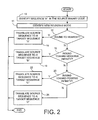
- FIG. 2 is a flowchart illustration according to some embodiments of the invention of an exemplary method to be implemented in a binary code translation module for translating a portion of a source binary code to a portion of a target binary code.
- FIGS- 3, 4, 5A and 5B are flowchart illustrations of exemplary instruction sequences to be generated by a binary code translation module, according to some embodiments of the invention.
- binary code translation module 2 may identify a sequence similar to exemplary sequence "A" in the source binary code (-10-) and may then identify the new rounding mode (-11-).
- binary code translation module 2 may translate source binary code sequence "A” into an equivalent target binary code sequence "A" (-14-) having floating point control instructions for changing rounding modes.
- binary code translation module 2 may translate source binary code sequence "A” into a target binary code sequence "B" (-18-), described in FIG. 3 .
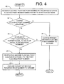
- binary code translation module 2 may translate source binary code sequence "A” into a target binary code sequence "C” (-22-), described in FIG. 4 .
- binary code translation module 2 may translate source binary code sequence "A” into a target binary code sequence "D" (-24-), described in FIGs. 5A and 5B .
- FIG. 3 is a flowchart illustration of the method of an exemplary target binary code sequence "B", according to some embodiments of the invention. It should be noted that the method of FIG. 3 may be executed by a target processor after checking that the floating point data is a suitable floating point number. For example, floating point data defined by ANSI/IEEE standard 754-1985 for binary floating-point arithmetic as "Infinite” or as "Quiet not a number" (QNaN) may not be suitable.
- a first floating point number is generated by rounding an initial floating point number using a round to zero forced mode instruction (-30-). If the first floating point number is positive (-32-) or if its value is equal to the value of the initial floating point number (-34-), then a result integer number is generated by converting the representation of the first floating point number to an integer representation (-36-). Otherwise, a second floating point number is generated by subtracting one from the first floating point number (-38-), and the result integer number is generated by converting the representation of the second floating point number to an integer representation (-39-).
- FIG. 4 is a flowchart illustration of the method of an exemplary target binary code sequence "C", according to some embodiments of the invention. It should be noted that the method of FIG. 3 may be executed by a target processor after checking that the floating point data is a suitable floating point number.
- a first floating point number is generated by rounding an initial floating point number using a round to zero forced mode instruction (-40-). If the first floating point number is negative (-42-) or if its value is equal to the value of the initial floating point number (-44-), then a result integer number is generated by converting the representation of the first floating point number to an integer representation (-46-). Otherwise, a second floating point number is generated by adding one to the first floating point number (-48-), and the result integer number is generated by converting the representation of the second floating point number to an integer representation (-49-).
- FIG. 5A is a flowchart illustration of the operation of an exemplary target binary code sequence "D", according to some embodiments of the invention.
- the floating point number is converted to an integer number using the round to zero mode (-50-).
- FIG. 5B is a flowchart illustration of the operation of another exemplary target binary code sequence "D", according to some embodiments of the invention.
- the initial floating point number is converted to a first floating point number using the round to zero forced mode instruction (-52-).
- the result integer number is generated by converting the representation of the first floating point number to an integer representation (-54-).
- FIG. 6 is a block diagram of an exemplary apparatus 60 according to some embodiments of the invention.
- Apparatus 60 may comprise a processor 62 and a memory 64 coupled to processor 62.
- Memory 64 may store a target binary code 66 generated by a binary-code translation module (not shown) using the method described in FIGS. 2 - 5 .
- Target binary code 66 complies with the architecture of processor 62.
- Processor 62 may execute target binary code 66.
- FIG. 7 is a block diagram of an exemplary apparatus 70 according to some embodiments of the invention.
- Apparatus 70 may comprise a processor 72 and a memory 74 coupled to processor 72.
- Memory 74 may store a source binary code 76 that does not comply with the architecture of processor 72, and a binary code translation module 78, suitable to translate source binary code 76 to a target binary code that complies with the architecture of processor 72.
- Processor 72 may execute binary code translation module 78 to translate source binary code 76 into a target binary code 80.
- Target binary code 80 may then be stored in memory 74 and may be executed by processor 72.
- source binary code 76, binary-code translation module 78 and target binary code 80 may be stored in separate memories that are coupled to processor 72.
- FIG. 8 is a block diagram of an exemplary apparatus according to some embodiments of the invention to translate source binary code to target binary code.
- Apparatus 90 may comprise a processor 92 and a memory 94 coupled to processor 92.
- Memory 94 may store a binary code translation module 96.
- Binary code translation module 96 may be able to translate a source binary code associated with a source processor architecture into a target binary code associated with a target processor architecture.
- the architecture of processor 92 may, or may not, comply with the source architecture and may, or may not, comply with the target architecture.
- Processor 92 may receive source binary code, may execute binary code translation module 96, and may output target binary code.
- a non-exhaustive list of examples for apparatuses 60, 70 and 90 includes a desktop personal computer, a work station, a server computer, a laptop computer, a notebook computer, a hand-held computer, a personal digital assistant (PDA), a mobile telephone, and the like.
- a desktop personal computer a work station
- a server computer a laptop computer
- a notebook computer a hand-held computer
- PDA personal digital assistant
- Processors 62, 72 and 92 includes a central processing unit (CPU), a digital signal processor (DSP), a reduced instruction set computer (RISC), a complex instructions set computer (CISC) and the like. Moreover, processors 62, 72 and 92 may be part of an application specific integrated circuit (ASIC) or may be a part of an application specific standard product (ASSP).
- CPU central processing unit
- DSP digital signal processor
- RISC reduced instruction set computer
- CISC complex instructions set computer
- ASIC application specific integrated circuit
- ASSP application specific standard product
- Memories 64, 74 and 94 may be fixed in or removable from apparatuses 60, 70 and 90, respectively,
- a non-exhaustive list of examples for memories 64, 74 and 94 includes any combination of the followings: semiconductor devices, such as synchronous dynamic random access Memory (SDRAM) devices, RAMBUS dynamic random access memory (RDRAM) devices, double data rate (DDR) memory devices, static random access memory (SRAM), flash memory devices, electrically erasable programmable read only memory devices (EEPROM), non-volatile random access memory devices (NVRAM), universal serial bus (USB) removable memory, and the like, optical devices, such as compact disk read only memory (CD ROM), and the like, and magnetic devices, such as a hard disk, a floppy disk, a magnetic tape, and the like.
- SDRAM synchronous dynamic random access Memory
- RDRAM RAMBUS dynamic random access memory
- DDR double data rate
- SRAM static random access memory
- flash memory devices electrically erasable programmable read only memory devices
Abstract
Description
- ANSI/IEEE standard 754-1985 for binary floating-point arithmetic defines four rounding modes to affect all arithmetic operations except comparison and remainder: round to nearest, round toward negative infinity, round toward positive infinity, and round to zero.
- In some processor architectures, prior to execution of an instruction to convert a floating point number to an integer using a specific rounding mode, the processing unit needs to be set to that rounding mode. This is achieved by reading and storing the current rounding mode, setting the processor architecture to the desired rounding mode, performing the conversion and setting processor architecture to the stored rounding mode. The instructions of setting the desired rounding mode and setting the stored rounding mode are examples of floating point control instructions.
- Execution of a floating point control instruction may be time consuming and may degrade the processor architecture performance.
- If a binary code associated with a first processor architecture having a first instruction set is to be executed by a second processor architecture having a second instruction set, a binary translation module may translate the source binary code into a target binary code associated with the second processor architecture. The results produced by executing the target binary code on a processor that complies with the target architecture are substantially the same as those produced by executing the source binary code on a processor that complies with the source architecture.
-
US2002/0032718 discloses an apparatus for converting instructions for a source computer architecture into instructions for a target computer architecture, The disclosed apparatus includes a memory device operable to store a stream of instructions for a source computer architecture; and a processor operable to process a stream of instructions stored in the memory device. The apparatus is such to generate a stream of instructions for a target computer architecture such that the stream of instructions when executed by a processor which complies with the target computer architecture generates the same results as occur when the original stream of instructions for said source computer architecture are executed by a processor which complies with said source computer architecture. -
US2002087609 discloses a system and method for rounding real numbers. The system includes a rounding apparatus to accept an input value that is a real number represented in floating-point format, and to perform a rounding operation on the input value to generate an output value that is an integer represented in floating-point format. The system also includes a memory to store a computer program that utilizes the rounding apparatus. The system further includes a central processing unit (CPU) to execute the computer program. The CPU is cooperatively connected to the rounding apparatus and the memory. - "Rounding-mode independent implementation of float-to-integer truncation", Research disclosure, Mason Publications, Hampshire. GB. Vol. 432, no. 58, April 2000 discloses a truncation operation which converts floating point data into signed integer by rounding toward zero. The document notes that where other forms of rounding conversion are required this is non-trivial and typically involves the steps of saving a current rounding mode, changing the selected rounding mode, executing a float-to integer conversion and restoring the original rounding mode. This traditional approach is stated to degrade performance.
-
US6535898 discloses a processor representation of a floating-point data item which is converted to a representation of a truncated integer item, without changing the rounding mode of a processor. When the current rounding mode is unknown, the floating-point item is converted to an integer representation in whatever mode the processor happens to be in. One of multiple correction values is applied, in response to the sign of the original data, a difference between the integer and the original data, and whether the item is an integer. When the current rounding mode is known, the processor produces two integer representations, and selects one or the other of them as an output integer data item, in response to the sign of the original item and the relative sizes of the two representations. - Intel Corporation: "Intel Architecture Optimization - Reference Manual", February 1999, retrieved from the internet URL: http://www.intel.co.jp/design/pentiumii/manuals/24512701.pdf discloses overviews of the architectures of the Pentium II and Pentium III processor.; the code development techniques to utilize the architecture of Pentium II and Pentium III processors as well as general strategies of efficient memory utilization; the following coding methodologies: assembly, inlined-assembly, intrinsics, vector classes, auto-vectorization, and libraries; strategies for altering data layout and restructuring algorithms for SIMD-style coding; optimization rules and techniques for high-performance integer and MMX™ technology applications; rules and optimization techniques, and provides code examples specific to floating-point code, including SIMD-floating point code for Streaming SIMD Extensions; the memory hierarchy of Pentium II and Pentium III processor Architectures, and how to best use it; the prefetch instruction and cache control management instructions for Streaming SIMD Extensions; application performance tools: VTune analyzer, Intel® Compiler plug-ins, and Intel® Performance Libraries Suite; for each tool, techniques and code optimization strategies that help to take advantage of the Intel architecture are described.
- In accordance with one aspect of the present invention there is provided a method of converting instructions for a source computer architecture into instructions for a target computer architecture in accordance with
claim 1. - In accordance with another aspect of the present invention there is provided an apparatus for converting instructions for a source computer architecture into instructions for a target computer architecture in accordance with claim 9.
- Embodiments of the invention are illustrated by way of example and not limitation in the figures of the accompanying drawings, in which like reference numerals indicate corresponding, analogous or similar elements, and in which:
-
FIG. 1 shows a binary-code translation module according to some embodiments of the invention; -
FIG. 2 is a flowchart illustration of an exemplary method to be implemented in a binary code translation module for translating a portion of a source binary code to a portion of a target binary code, according to some embodiments of the invention; -
FIGS. 3 ,4 ,5A and 5B are flowchart illustrations of exemplary instruction sequences to be generated by a binary code translation module, according to some embodiments of the invention; -
FIG. 6 is a block diagram of an exemplary apparatus according to some embodiments of the invention to store and execute target binary code; -
FIG. 7 is a block diagram of an exemplary apparatus according to some embodiments of the invention to translate source binary code to target binary code and to store and execute the target binary code; and -
FIG. 8 is a block diagram of yet another exemplary apparatus according to some embodiments of the invention to translate source binary code to target binary code. - It will be appreciated that for simplicity and clarity of illustration, elements shown in the figures have not necessarily been drawn to scale. For example, the dimensions of some of the elements may be exaggerated relative to other elements for clarity.
- In the following detailed description, numerous specific details are set forth in order to provide a thorough understanding of embodiments of the invention. However it will be understood by those of ordinary skill in the art that the embodiments of the invention may be practiced without these specific details. In other instances, well-known methods, procedures, components and circuits have not been described in detail so as not to obscure the embodiments of the invention.
- Some portions of the detailed description which follow are presented in terms of algorithms and symbolic representations of operations on data bits or binary digital signals within a computer memory. These algorithmic descriptions and representations may be the techniques used by those skilled in the data processing arts to convey the substance of their work to others skilled in the art.
- An algorithm is here, and generally, considered to be a self-consistent sequence of acts or operations leading to a desired result. These include physical manipulations of physical quantities. Usually, though not necessarily, these quantities take the form of electrical or magnetic signals capable of being stored, transferred, combined, compared, and otherwise manipulated. It has proven convenient at times, principally for reasons of common usage, to refer to these signals as bits, values, elements, symbols, characters, terms, numbers or the like. It should be understood, however, that all of these and similar terms are to be associated with the appropriate physical quantities and are merely convenient labels applied to these quantities.
- Unless specifically stated otherwise, as apparent from the following discussions, it is appreciated that throughout the specification discussions utilizing terms such as "processing," "computing," "calculating," "determining," or the like, refer to the action and/or processes of a computer or computing system, or similar electronic computing device, that manipulate and/or transform data represented as physical, such as electronic, quantities within the computing system's registers and/or memories into other data similarly represented as physical quantities within the computing system's memories, registers or other such information storage, transmission or display devices.
- Embodiments of the present invention may include apparatuses for performing the operations herein. This apparatus may be specially constructed for the desired purposes, or it may comprise a general purpose computer selectively activated or reconfigured by a computer program stored in the computer. Such a computer program may be stored in a computer readable storage medium, such as, but is not limited to, any type of disk including floppy disks, optical disks, CD-ROMs, magnetic-optical disks, read-only memories (ROMs), random access memories (RAMs), electrically programmable read-only memories (EPROMs), electrically erasable and programmable read only memories (EEPROMs), magnetic or optical cards, or any other type of media suitable for storing electronic instructions, and capable of being coupled to a computer system bus.
- The processes and displays presented herein are not inherently related to any particular computer or other apparatus. Various general purpose systems may be used with programs in accordance with the teachings herein, or it may prove convenient to construct a more specialized apparatus to perform the desired method. The desired structure for a variety of these systems will appear from the description below. In addition, embodiments of the present invention are not described with reference to any particular programming language. It will be appreciated that a variety of programming languages may be used to implement the teachings of the invention as described herein.
-
Fig. 1 shows a binary-code translation module 2 according to some embodiments of the invention. Binary-code translation module 2 may receive as input a binary code ("source binary code") associated with a first processor architecture having a first set of instructions ("source architecture"), and may output a binary code ("target binary code") associated with a second processor architecture having a second set of instructions ("target architecture")- The results produced by executing the target binary code on a processor that complies with the target architecture may be substantially the same as those produced by executing the source binary code on a processor that complies with the source architecture. - The instructions sets of both the source and target architectures may comply with ANSI/IEEE standard 754-1985 for binary floating-point arithmetic and may support conversion of floating point numbers to integer numbers using at least the four rounding modes defined in ANSI/IEEE standard 754-1985 to affect all arithmetic operations except comparison and remainder: round to nearest, round toward negative infinity, round toward positive infinity, and round to zero.
- It is understood by persons of ordinary skill in the art that a floating point number is implemented in a computer as a representation of a floating point number. Similarly, an integer number is implemented in a computer as a representation of a integer number. For example, 32 bits or 64 bits may be used to physically represent a floating point number, and 16 bits or 32 bits may be used to physically represent an integer number.
- Prior to execution of an instruction to convert a floating point number to an integer using a specific rounding mode in the source architecture, the source architecture may need to be set to that rounding mode by, for example, a floating point control instruction.
- If, for example, during execution of some portion of code, the source architecture is set to convert floating point numbers into integers using one rounding mode ("old rounding mode"), and during the execution of that code portion, a floating-point number is to be converted to integer using a second rounding mode ("new rounding mode"), the source architecture may need to execute the following exemplary sequence of four instructions (referred to as sequence "A"), :
- a.} save old rounding mode
- b.} execute floating point control instruction to set rounding mode to new rounding mode
- c.} convert floating point to integer using new rounding mode d-} execute floating point control instruction to set rounding mode to old rounding mode
- In sequence "A", instruction a} is followed by instruction b.}, instruction b.} is followed by instruction c.}, and instruction c.} is followed by instruction d.}. The term "followed by" means that a first instruction is executed after a second instruction, and other instructions may or may not be intervening between the second and the first instructions.
- Similarly, prior to execution of an instruction to convert a floating point number to an integer using a specific rounding mode in the target architecture, the target architecture may need to be set to that rounding mode by, for example, a floating point control instruction.
- If the instruction set of the target architecture comprises an instruction to round floating point numbers to floating point numbers using round to zero rounding mode, regardless of the rounding mode setting of the target architecture ("round to zero forced mode instruction"), it may be possible to avoid the use of a floating point control instruction to set the rounding mode in the target architecture.
- As shown in
FIGs. 2 ,3 ,4 ,5A and 5B , binary-code translation module 2 may use the round to zero forced mode instruction of the target architecture to translate a source binary code portion comprising a sequence "A" into a target binary code portion that does not include a floating point control instruction.. -
FIG. 2 is a flowchart illustration according to some embodiments of the invention of an exemplary method to be implemented in a binary code translation module for translating a portion of a source binary code to a portion of a target binary code. FIGS- 3, 4, 5A and 5B are flowchart illustrations of exemplary instruction sequences to be generated by a binary code translation module, according to some embodiments of the invention. - Referring to
FIG. 2 , binarycode translation module 2 may identify a sequence similar to exemplary sequence "A" in the source binary code (-10-) and may then identify the new rounding mode (-11-). - If the new rounding mode is round to nearest (-12-), then binary
code translation module 2 may translate source binary code sequence "A" into an equivalent target binary code sequence "A" (-14-) having floating point control instructions for changing rounding modes. - If the new rounding mode is round toward negative infinity (-16-), then binary
code translation module 2 may translate source binary code sequence "A" into a target binary code sequence "B" (-18-), described inFIG. 3 . - If the new rounding mode is round toward positive infinity (-20-), then binary
code translation module 2 may translate source binary code sequence "A" into a target binary code sequence "C" (-22-), described inFIG. 4 . - If the new rounding mode is round to zero, then binary
code translation module 2 may translate source binary code sequence "A" into a target binary code sequence "D" (-24-), described inFIGs. 5A and 5B . -
FIG. 3 is a flowchart illustration of the method of an exemplary target binary code sequence "B", according to some embodiments of the invention. It should be noted that the method ofFIG. 3 may be executed by a target processor after checking that the floating point data is a suitable floating point number. For example, floating point data defined by ANSI/IEEE standard 754-1985 for binary floating-point arithmetic as "Infinite" or as "Quiet not a number" (QNaN) may not be suitable. - A first floating point number is generated by rounding an initial floating point number using a round to zero forced mode instruction (-30-). If the first floating point number is positive (-32-) or if its value is equal to the value of the initial floating point number (-34-), then a result integer number is generated by converting the representation of the first floating point number to an integer representation (-36-). Otherwise, a second floating point number is generated by subtracting one from the first floating point number (-38-), and the result integer number is generated by converting the representation of the second floating point number to an integer representation (-39-).
-
FIG. 4 is a flowchart illustration of the method of an exemplary target binary code sequence "C", according to some embodiments of the invention. It should be noted that the method ofFIG. 3 may be executed by a target processor after checking that the floating point data is a suitable floating point number. - A first floating point number is generated by rounding an initial floating point number using a round to zero forced mode instruction (-40-). If the first floating point number is negative (-42-) or if its value is equal to the value of the initial floating point number (-44-), then a result integer number is generated by converting the representation of the first floating point number to an integer representation (-46-). Otherwise, a second floating point number is generated by adding one to the first floating point number (-48-), and the result integer number is generated by converting the representation of the second floating point number to an integer representation (-49-).
-
FIG. 5A is a flowchart illustration of the operation of an exemplary target binary code sequence "D", according to some embodiments of the invention. The floating point number is converted to an integer number using the round to zero mode (-50-).FIG. 5B is a flowchart illustration of the operation of another exemplary target binary code sequence "D", according to some embodiments of the invention. The initial floating point number is converted to a first floating point number using the round to zero forced mode instruction (-52-). The result integer number is generated by converting the representation of the first floating point number to an integer representation (-54-). -
FIG. 6 is a block diagram of anexemplary apparatus 60 according to some embodiments of the invention.Apparatus 60 may comprise aprocessor 62 and amemory 64 coupled toprocessor 62.Memory 64 may store atarget binary code 66 generated by a binary-code translation module (not shown) using the method described inFIGS. 2 - 5 . Targetbinary code 66 complies with the architecture ofprocessor 62.Processor 62 may execute targetbinary code 66. -
FIG. 7 is a block diagram of anexemplary apparatus 70 according to some embodiments of the invention.Apparatus 70 may comprise aprocessor 72 and amemory 74 coupled toprocessor 72.Memory 74 may store a sourcebinary code 76 that does not comply with the architecture ofprocessor 72, and a binarycode translation module 78, suitable to translate sourcebinary code 76 to a target binary code that complies with the architecture ofprocessor 72.Processor 72 may execute binarycode translation module 78 to translate sourcebinary code 76 into atarget binary code 80. Targetbinary code 80 may then be stored inmemory 74 and may be executed byprocessor 72. Alternatively, sourcebinary code 76, binary-code translation module 78 and targetbinary code 80 may be stored in separate memories that are coupled toprocessor 72. -
FIG. 8 is a block diagram of an exemplary apparatus according to some embodiments of the invention to translate source binary code to target binary code. -
Apparatus 90 may comprise aprocessor 92 and amemory 94 coupled toprocessor 92. -
Memory 94 may store a binarycode translation module 96. Binarycode translation module 96 may be able to translate a source binary code associated with a source processor architecture into a target binary code associated with a target processor architecture. The architecture ofprocessor 92 may, or may not, comply with the source architecture and may, or may not, comply with the target architecture. -
Processor 92 may receive source binary code, may execute binarycode translation module 96, and may output target binary code. - A non-exhaustive list of examples for
apparatuses - A non-exhaustive list of examples for
Processors processors -
Memories apparatuses memories
semiconductor devices, such as
synchronous dynamic random access Memory (SDRAM) devices, RAMBUS dynamic random access memory (RDRAM) devices, double data rate (DDR) memory devices, static random access memory (SRAM), flash memory devices, electrically erasable programmable read only memory devices (EEPROM), non-volatile random access memory devices (NVRAM), universal serial bus (USB) removable memory, and the like,
optical devices, such as
compact disk read only memory (CD ROM), and the like,
and magnetic devices, such as
a hard disk, a floppy disk, a magnetic tape, and the like. - White certain features of the invention have been illustrated and described herein, many modifications, substitutions, changes, and equivalents will now occur to those of ordinary skill in the art. It is, therefore, to be understood that the appended claims are intended to cover all such modifications and changes.
Claims (15)
- A computer-implemented method of converting instructions for a source computer architecture (76) into instructions for a target computer architecture (80), the method comprising:receiving a sequence of instructions for said source computer architecture (76);processing the received sequence (76); andgenerating a sequence of instructions (80) for said target computer architecture wherein said sequence of instructions (80) for said target computer architecture when executed by a processor which complies with said target computer architecture generates the same results as occur when said sequence of instructions (76) for said source computer architecture is executed by a processor which complies with said source computer architecture, characterised in that:processing said received sequence of instructions (76) includes identifying sequences (10) of instructions comprising: an instruction to save a first rounding mode, followed by an instruction to set a second rounding mode, followed by an instruction to generate an integer number by rounding a floating point number according to said second rounding mode, followed by an instruction to set said first rounding mode; andgenerating a sequence of instructions for said identified sequences comprises generating (14;18;22;24) sequences of instructions (80) for said target computer architecture which cause the generation of a rounded number rounded in accordance with the identified second rounding mode, without instructions to save data identifying said first rounding mode, wherein the rounding mode set after a rounding operation is performed comprises a round to zero rounding mode,wherein an instruction set of the target architecture comprises an instruction to round floating point numbers to floating point numbers using round to zero rounding mode, regardless of the rounding mode setting of the target architecture, called round to zero forced mode instruction.
- A method in accordance with claim 1 wherein generating a sequence of instructions (80) for said identified sequences comprises if said second rounding mode comprises round to zero, generating (24) an instruction for rounding a floating point number according to a mode selected from the group consisting of round to zero mode and round to zero forced mode without any instructions to save, set or reset a rounding mode.
- A method in accordance with claim 1 or 2, wherein generating a sequence of instructions (80) for said identified sequences if said second rounding mode comprises round to positive or negative infinity, comprises generating instructions (18;22) for rounding a floating point number according to a round to zero forced mode without any instructions to save, set or reset a round to zero forced mode together with further instructions to process a floating point number rounded to zero to obtain an integer equivalent to rounding using the identified second rounding mode in the identified sequence of instructions.
- A method in accordance with claim 3, wherein if said second rounding mode comprises round to positive infinity said further instructions to process a floating point number rounded to zero comprise instructions to:determine whether a generated rounded floating point number is positive and if a generated rounded floating point number is positive and the generated floating point number is not equal to the floating point number prior to rounding to add one to the generated floating point number.
- A method in accordance with claim 3, wherein if said second rounding mode comprises round to negative infinity said further instructions to process a floating point number rounded to zero comprise instructions to:determine whether a generated rounded floating point number is negative and if a generated rounded floating point number is negative and the generated floating point number is not equal to the floating point number prior to rounding to subtract one from the generated floating point number.
- A method in accordance with any preceding claim, wherein generating (14;18;22;24) a sequence of instructions for said identified sequences if said second rounding mode comprises round to nearest, comprises generating (14) an equivalent sequence of instructions having floating-point control instructions for changing rounding modes.
- A method in accordance with any preceding claim, wherein generating (14) a sequence of instructions for said identified sequences further includes an instruction for converting a floating point representation of generated rounded floating point number into an integer representation of the generated rounded floating point number.
- A computer readable medium storing computer implementable instructions which when executed by a programmable computer cause the computer to convert instructions for a source computer architecture (76) into instructions for a target computer architecture (80) by performing a method in accordance with any of claims 1-7.
- An apparatus for converting instructions for a source computer architecture (76) into instructions for a target computer architecture (80), the apparatus comprising:a memory device (74) operable to store a sequence of instructions for a source computer architecture (76); anda processor (72) operable to process a sequence of instructions stored in said memory device (74) and generate a sequence of instructions for a target computer architecture (80) wherein said sequence of instructions for said target computer architecture (80) when executed by a processor which complies with said target computer architecture (80) generates the same results as occur when said sequence of instructions for said source computer architecture (76) is executed by a processor which complies with said source computer architecture (76), characterised by said processor (72) being operable to:process a stored sequence of instructions by identifying (10) sequences of instructions comprising: an instruction to save a first rounding mode, followed by an instruction to set a second rounding mode, followed by an instruction to generate an integer number by rounding a floating point number according to said second rounding mode, followed by an instruction to set said first rounding mode; andgenerate a sequence of instructions for said identified sequences by generating (12;18;22;24) sequences of instructions for said target computer architecture (80) which cause the generation of a rounded number rounded in accordance with the identified second rounding mode, without instructions to save data identifying said first rounding mode, wherein the rounding mode set after a rounding operation is performed comprises a round to zero rounding mode,wherein an instruction set of the target architecture comprises an instruction to round floating point numbers to floating point numbers using round to zero rounding mode, regardless of the rounding mode setting of the target architecture, called round to zero forced mode instruction.
- An apparatus in accordance with claim 9 wherein said processor (72) is operable to generate (24) a sequence of instructions for said identified sequences by if said second rounding mode comprises round to zero, generating an instruction for rounding a floating point number according to a mode selected from the group consisting of round to zero mode and round to zero forced mode without any instructions to save, set or reset a rounding mode.
- An apparatus in accordance with claim 9 or 10 wherein said processor (72) is operable to generate a sequence of instructions for said identified sequences by if said second rounding mode comprises round to positive or negative infinity, generating (18;22) instructions for round a floating point number according to a round to zero forced mode without any instructions to save, set or reset a round to zero forced mode together with further instructions to process a floating point number rounded to zero to obtain an integer equivalent to rounding using the identified second rounding mode in the identified sequence of instructions.
- An apparatus in accordance with claim 11 wherein said processor (72) is operable to generate (22) a sequence of instructions for said identified sequences wherein if said second rounding mode comprises round to positive infinity said further instructions to process a floating point number rounded to zero comprise instructions to:determine whether a generated rounded floating point number is positive and if a generated rounded floating point number is positive and the generated floating point number is not equal to the floating point number prior to rounding to add one to the generated floating point number.
- An apparatus in accordance with claim 11 wherein said processor (72) is operable to generate (22) a sequence of instructions for said identified sequences wherein if said second rounding mode comprises round to negative infinity said further instructions to process a floating point number rounded to zero comprise instructions to:determine whether a generated rounded floating point number is negative and if a generated rounded floating point number is negative and the generated floating point number is not equal to the floating point number prior to rounding to subtract one from the generated floating point number.
- An apparatus in accordance with any of claims 9-13 wherein said processor (72) is operable to generate (14) a sequence of instructions for said identified sequences wherein if said second rounding mode comprises round to nearest, generating an equivalent sequence of instructions having floating-point control instructions for changing rounding modes.
- An apparatus in accordance with any of claims 9-14 wherein said processor (72) is operable to generate (14;18;22;24) a sequence of instructions for said identified sequences wherein generating a sequence of instructions for said identified sequences further includes an instruction for converting a floating point representation of generated rounded floating point number into an integer representation of the generated rounded floating point number.
Applications Claiming Priority (2)
| Application Number | Priority Date | Filing Date | Title |
|---|---|---|---|
| US10/743,307 US7380240B2 (en) | 2003-12-23 | 2003-12-23 | Apparatus and methods to avoid floating point control instructions in floating point to integer conversion |
| PCT/US2004/041849 WO2005066777A2 (en) | 2003-12-23 | 2004-12-15 | Apparatus and methods to avoid floating point control instructions in floating point to integer conversion |
Publications (2)
| Publication Number | Publication Date |
|---|---|
| EP1700208A2 EP1700208A2 (en) | 2006-09-13 |
| EP1700208B1 true EP1700208B1 (en) | 2010-10-06 |
Family
ID=34678633
Family Applications (1)
| Application Number | Title | Priority Date | Filing Date |
|---|---|---|---|
| EP04814077A Not-in-force EP1700208B1 (en) | 2003-12-23 | 2004-12-15 | Apparatus and method to avoid floating point control instructions in floating point to integer conversion |
Country Status (6)
| Country | Link |
|---|---|
| US (1) | US7380240B2 (en) |
| EP (1) | EP1700208B1 (en) |
| CN (1) | CN1894665B (en) |
| AT (1) | ATE484023T1 (en) |
| DE (1) | DE602004029499D1 (en) |
| WO (1) | WO2005066777A2 (en) |
Families Citing this family (4)
| Publication number | Priority date | Publication date | Assignee | Title |
|---|---|---|---|---|
| US7765579B2 (en) * | 2004-09-07 | 2010-07-27 | Greencastle Technology, Inc. | Security deployment system |
| US9223751B2 (en) | 2006-09-22 | 2015-12-29 | Intel Corporation | Performing rounding operations responsive to an instruction |
| US8327120B2 (en) | 2007-12-29 | 2012-12-04 | Intel Corporation | Instructions with floating point control override |
| JP5279646B2 (en) * | 2008-09-03 | 2013-09-04 | キヤノン株式会社 | Information processing apparatus, operation method thereof, and program |
Family Cites Families (11)
| Publication number | Priority date | Publication date | Assignee | Title |
|---|---|---|---|---|
| US5652862A (en) * | 1992-12-30 | 1997-07-29 | Apple Computer, Inc. | Method and appartus for determining a precision of an intermediate arithmetic for converting values between a first numeric format and a second numeric format |
| US6535903B2 (en) | 1996-01-29 | 2003-03-18 | Compaq Information Technologies Group, L.P. | Method and apparatus for maintaining translated routine stack in a binary translation environment |
| US5889984A (en) * | 1996-08-19 | 1999-03-30 | Intel Corporation | Floating point and integer condition compatibility for conditional branches and conditional moves |
| US6131104A (en) * | 1998-03-27 | 2000-10-10 | Advanced Micro Devices, Inc. | Floating point addition pipeline configured to perform floating point-to-integer and integer-to-floating point conversion operations |
| US6266769B1 (en) * | 1998-04-30 | 2001-07-24 | Intel Corporation | Conversion between packed floating point data and packed 32-bit integer data in different architectural registers |
| US6965906B1 (en) * | 1999-08-19 | 2005-11-15 | National Semiconductor Corporation | Converting negative floating point numbers to integer notation without two's complement hardware |
| US6460177B1 (en) * | 1999-09-22 | 2002-10-01 | Lucent Technologies Inc. | Method for target-specific development of fixed-point algorithms employing C++ class definitions |
| US6535898B1 (en) * | 2000-01-24 | 2003-03-18 | Microsoft Corporation | Fast floating-point truncation to integer form |
| US6879992B2 (en) | 2000-12-27 | 2005-04-12 | Intel Corporation | System and method to efficiently round real numbers |
| US20040248094A1 (en) * | 2002-06-12 | 2004-12-09 | Ford Lance P. | Methods and compositions relating to labeled RNA molecules that reduce gene expression |
| US7299170B2 (en) * | 2003-06-28 | 2007-11-20 | Transitive Limited | Method and apparatus for the emulation of high precision floating point instructions |
-
2003
- 2003-12-23 US US10/743,307 patent/US7380240B2/en not_active Expired - Fee Related
-
2004
- 2004-12-15 DE DE602004029499T patent/DE602004029499D1/en active Active
- 2004-12-15 AT AT04814077T patent/ATE484023T1/en not_active IP Right Cessation
- 2004-12-15 CN CN200480037051.6A patent/CN1894665B/en not_active Expired - Fee Related
- 2004-12-15 EP EP04814077A patent/EP1700208B1/en not_active Not-in-force
- 2004-12-15 WO PCT/US2004/041849 patent/WO2005066777A2/en not_active Application Discontinuation
Also Published As
| Publication number | Publication date |
|---|---|
| EP1700208A2 (en) | 2006-09-13 |
| DE602004029499D1 (en) | 2010-11-18 |
| US7380240B2 (en) | 2008-05-27 |
| WO2005066777A3 (en) | 2006-05-11 |
| US20050138608A1 (en) | 2005-06-23 |
| WO2005066777A2 (en) | 2005-07-21 |
| CN1894665A (en) | 2007-01-10 |
| ATE484023T1 (en) | 2010-10-15 |
| CN1894665B (en) | 2013-05-08 |
Similar Documents
| Publication | Publication Date | Title |
|---|---|---|
| US7353368B2 (en) | Method and apparatus for achieving architectural correctness in a multi-mode processor providing floating-point support | |
| EP1232430B1 (en) | Optimization of n-base typed arithmetic expressions | |
| KR101642556B1 (en) | Methods and systems for performing a binary translation | |
| RU2638766C2 (en) | Processors, methods, systems and instructions for transcoding points of unicode variable length code | |
| US8745111B2 (en) | Methods and apparatuses for converting floating point representations | |
| CN110879724A (en) | FP16-S7E8 hybrid accuracy for deep learning and other algorithms | |
| EP3719639A2 (en) | Systems and methods to perform floating-point addition with selected rounding | |
| CN104049945A (en) | Methods and apparatus for fusing instructions to provide or-test and and-test functionality on multiple test sources | |
| CN104050077A (en) | Fusible instructions and logic to provide or-test and and-test functionality using multiple test sources | |
| JP2021525403A (en) | Improved low precision binary floating point formatting | |
| CN101488083A (en) | Methods, apparatus, and instructions for converting vector data | |
| CN110023903B (en) | Binary vector factorization | |
| CN103959239A (en) | Conditional execution support for isa instructions using prefixes | |
| CN114691211A (en) | Instruction to transition from FP16 to BF8 | |
| US7752028B2 (en) | Signed/unsigned integer guest compare instructions using unsigned host compare instructions for precise architecture emulation | |
| EP1700208B1 (en) | Apparatus and method to avoid floating point control instructions in floating point to integer conversion | |
| US8140608B1 (en) | Pipelined integer division using floating-point reciprocal | |
| US9134751B2 (en) | Time keeping in unknown and unstable clock architecture | |
| US7774764B2 (en) | Method and system for efficient range and stride checking | |
| KR20080018692A (en) | Method, programming structure and recordable medium for performing fast floating point operation for various precisions | |
| CN117008971B (en) | Conversion method and device of WebAsssembly instruction set | |
| US20050149913A1 (en) | Apparatus and methods to optimize code in view of masking status of exceptions | |
| US20230161555A1 (en) | System and method performing floating-point operations | |
| CN104823153A (en) | Leading change anticipator logic | |
| CN116610362B (en) | Method, system, equipment and storage medium for decoding instruction set of processor |
Legal Events
| Date | Code | Title | Description |
|---|---|---|---|
| PUAI | Public reference made under article 153(3) epc to a published international application that has entered the european phase |
Free format text: ORIGINAL CODE: 0009012 |
|
| 17P | Request for examination filed |
Effective date: 20060602 |
|
| AK | Designated contracting states |
Kind code of ref document: A2 Designated state(s): AT BE BG CH CY CZ DE DK EE ES FI FR GB GR HU IE IS IT LI LT LU MC NL PL PT RO SE SI SK TR |
|
| AX | Request for extension of the european patent |
Extension state: AL BA HR LV MK YU |
|
| 17Q | First examination report despatched |
Effective date: 20061122 |
|
| DAX | Request for extension of the european patent (deleted) | ||
| GRAP | Despatch of communication of intention to grant a patent |
Free format text: ORIGINAL CODE: EPIDOSNIGR1 |
|
| RTI1 | Title (correction) |
Free format text: APPARATUS AND METHOD TO AVOID FLOATING POINT CONTROL INSTRUCTIONS IN FLOATING POINT TO INTEGER CONVERSION |
|
| GRAS | Grant fee paid |
Free format text: ORIGINAL CODE: EPIDOSNIGR3 |
|
| GRAA | (expected) grant |
Free format text: ORIGINAL CODE: 0009210 |
|
| AK | Designated contracting states |
Kind code of ref document: B1 Designated state(s): AT BE BG CH CY CZ DE DK EE ES FI FR GB GR HU IE IS IT LI LT LU MC NL PL PT RO SE SI SK TR |
|
| REG | Reference to a national code |
Ref country code: GB Ref legal event code: FG4D |
|
| REG | Reference to a national code |
Ref country code: CH Ref legal event code: EP |
|
| REG | Reference to a national code |
Ref country code: IE Ref legal event code: FG4D |
|
| REF | Corresponds to: |
Ref document number: 602004029499 Country of ref document: DE Date of ref document: 20101118 Kind code of ref document: P |
|
| REG | Reference to a national code |
Ref country code: NL Ref legal event code: VDEP Effective date: 20101006 |
|
| PG25 | Lapsed in a contracting state [announced via postgrant information from national office to epo] |
Ref country code: SI Free format text: LAPSE BECAUSE OF FAILURE TO SUBMIT A TRANSLATION OF THE DESCRIPTION OR TO PAY THE FEE WITHIN THE PRESCRIBED TIME-LIMIT Effective date: 20101006 |
|
| LTIE | Lt: invalidation of european patent or patent extension |
Effective date: 20101006 |
|
| PG25 | Lapsed in a contracting state [announced via postgrant information from national office to epo] |
Ref country code: LT Free format text: LAPSE BECAUSE OF FAILURE TO SUBMIT A TRANSLATION OF THE DESCRIPTION OR TO PAY THE FEE WITHIN THE PRESCRIBED TIME-LIMIT Effective date: 20101006 |
|
| PG25 | Lapsed in a contracting state [announced via postgrant information from national office to epo] |
Ref country code: NL Free format text: LAPSE BECAUSE OF FAILURE TO SUBMIT A TRANSLATION OF THE DESCRIPTION OR TO PAY THE FEE WITHIN THE PRESCRIBED TIME-LIMIT Effective date: 20101006 Ref country code: IS Free format text: LAPSE BECAUSE OF FAILURE TO SUBMIT A TRANSLATION OF THE DESCRIPTION OR TO PAY THE FEE WITHIN THE PRESCRIBED TIME-LIMIT Effective date: 20110206 Ref country code: FI Free format text: LAPSE BECAUSE OF FAILURE TO SUBMIT A TRANSLATION OF THE DESCRIPTION OR TO PAY THE FEE WITHIN THE PRESCRIBED TIME-LIMIT Effective date: 20101006 Ref country code: AT Free format text: LAPSE BECAUSE OF FAILURE TO SUBMIT A TRANSLATION OF THE DESCRIPTION OR TO PAY THE FEE WITHIN THE PRESCRIBED TIME-LIMIT Effective date: 20101006 Ref country code: SE Free format text: LAPSE BECAUSE OF FAILURE TO SUBMIT A TRANSLATION OF THE DESCRIPTION OR TO PAY THE FEE WITHIN THE PRESCRIBED TIME-LIMIT Effective date: 20101006 Ref country code: BG Free format text: LAPSE BECAUSE OF FAILURE TO SUBMIT A TRANSLATION OF THE DESCRIPTION OR TO PAY THE FEE WITHIN THE PRESCRIBED TIME-LIMIT Effective date: 20110106 Ref country code: PT Free format text: LAPSE BECAUSE OF FAILURE TO SUBMIT A TRANSLATION OF THE DESCRIPTION OR TO PAY THE FEE WITHIN THE PRESCRIBED TIME-LIMIT Effective date: 20110207 |
|
| PG25 | Lapsed in a contracting state [announced via postgrant information from national office to epo] |
Ref country code: BE Free format text: LAPSE BECAUSE OF FAILURE TO SUBMIT A TRANSLATION OF THE DESCRIPTION OR TO PAY THE FEE WITHIN THE PRESCRIBED TIME-LIMIT Effective date: 20101006 Ref country code: GR Free format text: LAPSE BECAUSE OF FAILURE TO SUBMIT A TRANSLATION OF THE DESCRIPTION OR TO PAY THE FEE WITHIN THE PRESCRIBED TIME-LIMIT Effective date: 20110107 |
|
| PG25 | Lapsed in a contracting state [announced via postgrant information from national office to epo] |
Ref country code: MC Free format text: LAPSE BECAUSE OF NON-PAYMENT OF DUE FEES Effective date: 20101231 Ref country code: ES Free format text: LAPSE BECAUSE OF FAILURE TO SUBMIT A TRANSLATION OF THE DESCRIPTION OR TO PAY THE FEE WITHIN THE PRESCRIBED TIME-LIMIT Effective date: 20110117 Ref country code: EE Free format text: LAPSE BECAUSE OF FAILURE TO SUBMIT A TRANSLATION OF THE DESCRIPTION OR TO PAY THE FEE WITHIN THE PRESCRIBED TIME-LIMIT Effective date: 20101006 Ref country code: CZ Free format text: LAPSE BECAUSE OF FAILURE TO SUBMIT A TRANSLATION OF THE DESCRIPTION OR TO PAY THE FEE WITHIN THE PRESCRIBED TIME-LIMIT Effective date: 20101006 |
|
| REG | Reference to a national code |
Ref country code: CH Ref legal event code: PL |
|
| PLBE | No opposition filed within time limit |
Free format text: ORIGINAL CODE: 0009261 |
|
| STAA | Information on the status of an ep patent application or granted ep patent |
Free format text: STATUS: NO OPPOSITION FILED WITHIN TIME LIMIT |
|
| PG25 | Lapsed in a contracting state [announced via postgrant information from national office to epo] |
Ref country code: DK Free format text: LAPSE BECAUSE OF FAILURE TO SUBMIT A TRANSLATION OF THE DESCRIPTION OR TO PAY THE FEE WITHIN THE PRESCRIBED TIME-LIMIT Effective date: 20101006 Ref country code: PL Free format text: LAPSE BECAUSE OF FAILURE TO SUBMIT A TRANSLATION OF THE DESCRIPTION OR TO PAY THE FEE WITHIN THE PRESCRIBED TIME-LIMIT Effective date: 20101006 Ref country code: RO Free format text: LAPSE BECAUSE OF FAILURE TO SUBMIT A TRANSLATION OF THE DESCRIPTION OR TO PAY THE FEE WITHIN THE PRESCRIBED TIME-LIMIT Effective date: 20101006 Ref country code: SK Free format text: LAPSE BECAUSE OF FAILURE TO SUBMIT A TRANSLATION OF THE DESCRIPTION OR TO PAY THE FEE WITHIN THE PRESCRIBED TIME-LIMIT Effective date: 20101006 |
|
| REG | Reference to a national code |
Ref country code: FR Ref legal event code: ST Effective date: 20110831 |
|
| 26N | No opposition filed |
Effective date: 20110707 |
|
| PG25 | Lapsed in a contracting state [announced via postgrant information from national office to epo] |
Ref country code: IE Free format text: LAPSE BECAUSE OF NON-PAYMENT OF DUE FEES Effective date: 20101215 Ref country code: CH Free format text: LAPSE BECAUSE OF NON-PAYMENT OF DUE FEES Effective date: 20101231 Ref country code: LI Free format text: LAPSE BECAUSE OF NON-PAYMENT OF DUE FEES Effective date: 20101231 Ref country code: FR Free format text: LAPSE BECAUSE OF NON-PAYMENT OF DUE FEES Effective date: 20110103 |
|
| REG | Reference to a national code |
Ref country code: DE Ref legal event code: R097 Ref document number: 602004029499 Country of ref document: DE Effective date: 20110707 |
|
| PG25 | Lapsed in a contracting state [announced via postgrant information from national office to epo] |
Ref country code: IT Free format text: LAPSE BECAUSE OF FAILURE TO SUBMIT A TRANSLATION OF THE DESCRIPTION OR TO PAY THE FEE WITHIN THE PRESCRIBED TIME-LIMIT Effective date: 20101006 |
|
| PG25 | Lapsed in a contracting state [announced via postgrant information from national office to epo] |
Ref country code: CY Free format text: LAPSE BECAUSE OF FAILURE TO SUBMIT A TRANSLATION OF THE DESCRIPTION OR TO PAY THE FEE WITHIN THE PRESCRIBED TIME-LIMIT Effective date: 20101006 |
|
| PG25 | Lapsed in a contracting state [announced via postgrant information from national office to epo] |
Ref country code: HU Free format text: LAPSE BECAUSE OF FAILURE TO SUBMIT A TRANSLATION OF THE DESCRIPTION OR TO PAY THE FEE WITHIN THE PRESCRIBED TIME-LIMIT Effective date: 20110407 Ref country code: LU Free format text: LAPSE BECAUSE OF NON-PAYMENT OF DUE FEES Effective date: 20101215 |
|
| PG25 | Lapsed in a contracting state [announced via postgrant information from national office to epo] |
Ref country code: TR Free format text: LAPSE BECAUSE OF FAILURE TO SUBMIT A TRANSLATION OF THE DESCRIPTION OR TO PAY THE FEE WITHIN THE PRESCRIBED TIME-LIMIT Effective date: 20101006 |
|
| PGFP | Annual fee paid to national office [announced via postgrant information from national office to epo] |
Ref country code: GB Payment date: 20141210 Year of fee payment: 11 Ref country code: DE Payment date: 20141209 Year of fee payment: 11 |
|
| REG | Reference to a national code |
Ref country code: DE Ref legal event code: R119 Ref document number: 602004029499 Country of ref document: DE |
|
| GBPC | Gb: european patent ceased through non-payment of renewal fee |
Effective date: 20151215 |
|
| PG25 | Lapsed in a contracting state [announced via postgrant information from national office to epo] |
Ref country code: GB Free format text: LAPSE BECAUSE OF NON-PAYMENT OF DUE FEES Effective date: 20151215 Ref country code: DE Free format text: LAPSE BECAUSE OF NON-PAYMENT OF DUE FEES Effective date: 20160701 |