EP1698988A1 - Image processing apparatus and its method - Google Patents
Image processing apparatus and its method Download PDFInfo
- Publication number
- EP1698988A1 EP1698988A1 EP06110473A EP06110473A EP1698988A1 EP 1698988 A1 EP1698988 A1 EP 1698988A1 EP 06110473 A EP06110473 A EP 06110473A EP 06110473 A EP06110473 A EP 06110473A EP 1698988 A1 EP1698988 A1 EP 1698988A1
- Authority
- EP
- European Patent Office
- Prior art keywords
- image
- vector
- additional information
- vector conversion
- data
- Prior art date
- Legal status (The legal status is an assumption and is not a legal conclusion. Google has not performed a legal analysis and makes no representation as to the accuracy of the status listed.)
- Withdrawn
Links
- 238000012545 processing Methods 0.000 title claims abstract description 79
- 238000000034 method Methods 0.000 title claims description 35
- 239000013598 vector Substances 0.000 claims abstract description 163
- 238000006243 chemical reaction Methods 0.000 claims abstract description 105
- 238000003672 processing method Methods 0.000 claims description 9
- 238000001514 detection method Methods 0.000 claims description 8
- 238000013475 authorization Methods 0.000 claims description 6
- 238000004590 computer program Methods 0.000 claims 4
- 230000002950 deficient Effects 0.000 abstract description 6
- 238000012015 optical character recognition Methods 0.000 description 18
- 230000006870 function Effects 0.000 description 13
- 230000015654 memory Effects 0.000 description 5
- 230000011218 segmentation Effects 0.000 description 5
- 238000010586 diagram Methods 0.000 description 4
- 238000000605 extraction Methods 0.000 description 4
- 238000003491 array Methods 0.000 description 3
- 230000001174 ascending effect Effects 0.000 description 2
- 238000009826 distribution Methods 0.000 description 2
- 230000002093 peripheral effect Effects 0.000 description 2
- 230000002265 prevention Effects 0.000 description 2
- 238000004458 analytical method Methods 0.000 description 1
- 230000005540 biological transmission Effects 0.000 description 1
- 238000004364 calculation method Methods 0.000 description 1
- 239000003086 colorant Substances 0.000 description 1
- 238000004891 communication Methods 0.000 description 1
- 238000000354 decomposition reaction Methods 0.000 description 1
- 230000007812 deficiency Effects 0.000 description 1
- 230000001419 dependent effect Effects 0.000 description 1
- 238000011156 evaluation Methods 0.000 description 1
- 239000000284 extract Substances 0.000 description 1
- 239000003550 marker Substances 0.000 description 1
- 230000003287 optical effect Effects 0.000 description 1
- 238000005192 partition Methods 0.000 description 1
- 230000004044 response Effects 0.000 description 1
Images


Classifications
-
- G—PHYSICS
- G06—COMPUTING; CALCULATING OR COUNTING
- G06F—ELECTRIC DIGITAL DATA PROCESSING
- G06F16/00—Information retrieval; Database structures therefor; File system structures therefor
- G06F16/50—Information retrieval; Database structures therefor; File system structures therefor of still image data
- G06F16/58—Retrieval characterised by using metadata, e.g. metadata not derived from the content or metadata generated manually
- G06F16/583—Retrieval characterised by using metadata, e.g. metadata not derived from the content or metadata generated manually using metadata automatically derived from the content
Definitions
- the present invention relates to an image processing apparatus and its method and, more particularly, to image processing for generating reusable data from a document image.
- Japanese Patent Laid-Open No. 2004-164538 describes a method of determining whether or not a document, the image of which is read, is a confidential document. That is, with this technique, the copy-forgery-prohibit-pattern of a confidential document is registered in advance, and it is checked if the copy-forgery-prohibit-pattern of the read document image matches the registered copy-forgery-prohibit-pattern, thus checking whether or not the read image is that of a confidential document.
- the first aspect of the present invention discloses an image processing method comprising the steps of: reading a document image; extracting additional information of the read document image; and controlling to restrict vector conversion to be applied to the document image to vector conversion for a search, which searches a data file corresponding to the document image, in accordance with the extracted additional information.
- the second aspect of the present invention discloses an image processing method comprising the steps of: reading a document image; dividing the read image in accordance with attributes of image regions; inputting designation of an image region to which vector conversion is to be applied of the divided image regions; vector-converting an image of the designated image region; detecting a data file corresponding to the image of the designated image region by search; generating reusable.data using at least one of images of the divided image regions, the detected data file, and vector data obtained by the vector conversion; extracting additional information included in the designated image region; and controlling operations of the vector conversion, and the detecting step and generating step in accordance with the extracted additional information.
- the search efficiency and search precision can be improved while maintaining high security.
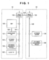
- Fig. 1 is a block diagram showing the arrangement of an image processing system which digitizes information using a multi-functional peripheral equipment (MFP) as a recording apparatus whose functions are expanded.
- MFP multi-functional peripheral equipment
- This image processing system is implemented in an environment in which offices (or a plurality of office-like partitions) 10 and 20 are connected via a wide area network (WAN) 104 such as the Internet or the like.
- WAN wide area network
- a local area network (LAN) 107 formed in the office 10 an MFP 100, a management PC 101 which controls the MFP 100, a client PC 102, a document management server 106, a database server 105 managed by the document management server 106, and the like are connected.
- the offices 10 and 20 have substantially the same arrangements.
- a LAN 108 formed in the office 20 at least a document management server 106, a database server 105 managed by the document management server 106, and the like are connected.
- the LANs 107 and 108 of the offices 10 and 20 are connected to each other via a proxy server 103 connected to the LAN 107, the WAN 104, and another proxy server 103 connected to the LAN 108.
- the MFP 100 does some of image processes for reading a document image, and processing a read image.
- An image signal output from the MFP 100 is input to the management PC 101 via a communication line 109.
- the management PC 101 comprises a normal personal computer (PC).
- the management PC 101 has a memory such as a hard disk or the like for storing images, an image processor implemented by hardware or software, a monitor such as a CRT, LCD, or the like, and an input unit including a mouse, keyboard, and the like.
- Some components of the management PC 101 are integrally formed with the MFP 100. Note that a case will be exemplified hereinafter wherein the management PC 101 executes search processing and the like to be described later, but the MFP 100 may execute the processing to be executed by the management PC 101.
- Fig. 2 is a block diagram showing the arrangement of the MFP 100.
- An image reader 110 including an auto document feeder (ADF) irradiates an image on each of one or a plurality of stacked documents with light coming from a light source, and forms an image of light reflected by the document on a solid-state image sensing element via a lens. Then, the image reader 110 obtains a read image signal (e.g., 600 dpi, 8 bits) in the raster order from the solid-state image sensing element.
- a data processor 115 converts this read image signal into a print signal.
- the data processor 115 temporarily stores a print signal for one page in a storage unit 111, and repetitively outputs the print signal to a printer unit 112, thus forming images on the plurality of print sheets.
- print data output from the client PC 102 is input to a network interface (I/F) 114 via the LAN 107.
- the print data is converted into printable raster data by the data processor 115, and is formed by the printer unit 112 as an image on a print sheet.
- An input unit 113 which includes a key operation unit equipped on the MFP 100 and a keyboard and mouse of the management PC 101 is used to input operator's instruction to the MFP 100.
- a display unit 116 displays operation inputs, image processing states, and the like.
- the operation of the MFP 100 is controlled by a controller 115a which is included in the data processor 115 and comprises, e.g., a one-chip microcontroller.
- the storage unit 111 can also be controlled from the management PC 101. Data exchange and control between the MFP 100 and management PC 101 are made via a network I/F 117 and the signal line 109 which directly connects them.
- the MFP 100 may comprise an interface which acquires image data from an image sensing apparatus such as a digital camera, digital video, or the like, a portable terminal such as a portable data assistant (PDA), a facsimile, or the like as a part of the input unit 113.
- an image sensing apparatus such as a digital camera, digital video, or the like
- a portable terminal such as a portable data assistant (PDA), a facsimile, or the like as a part of the input unit 113.
- PDA portable data assistant
- a user recognition unit 118 used to identify the user is connected to the input unit 113.
- the user recognition unit 118 is, e.g., an IC card reader, keys used to input an ID or password, a biometric device that identifies biometric information such as fingerprints, a handprint, a capillary pattern, an iris, or the like.
- the user recognition unit 118 inputs information that specifies the user who uses the MFP 100 (to be referred to as "user specifying information” hereinafter), and outputs the user specifying information to the data processor 115 via the input unit 113.
- information indicating the security level of each user of the MFP 100 is set and stored in a nonvolatile memory of the data processor 115 or that of the management PC 101 (e.g., a hard disk). Therefore, the data processor 115 can acquire the security level, which is corresponds to the user specifying information input from the user recognition unit 118, from anyone of the nonvolatile memories.
- the user recognition unit 118 may notify the data processor 115 of the security level stored in a memory in an IC card.
- an event that the data processor 115 acquires the security level corresponding to the user specifying information acquired by the user recognition unit 118 (or it directly acquires the security level from the user recognition unit 118) will be referred to as "user authorization”.
- Data transmission and storage in the MFP 100 are instructed from the input unit 113 or client PC 102 to the management PC 101.
- an image signal read by the image reader 110 or received from the client PC 102 is converted into a print signal by the data processor 115, and is then transmitted via the network I/F 114 (or 117) or stored in the storage unit 111.
- an instruction for converting a document image into reusable digital data is sent from the input unit 113 to the management PC 101.
- an image signal read by the image reader 110 undergoes vector conversion (which will be described later) by the management PC 101, and is then transmitted via the network I/F 114 (or 117) or stored in the storage unit 111.
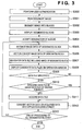
- Fig. 3 is a flowchart for explaining the flow of the processing by the aforementioned image processing system. This processing is executed by the management PC 101 or data processor 115 or a combination of them.
- the MFP 100 performs user authorization (S300). If user authorization has failed, the MFP 100 displays a message that advises accordingly on the display unit 116, and does not accept any operation. If user authorization has succeeded, the MFP 100 enables the image reader 110 to.scan a document image for one page in a raster order, thus acquiring a read image signal.
- the read image signal is pre-processed by the data processor 115, and is saved in the storage unit 111 as image data for one page of the input image (S301).
- the management PC 101 performs block selection (BS) processing on the image data stored in the storage unit 111 to segment the image data into a text and line region including character or line images, a halftone photo region, an image region with an indeterminate form, and other regions. Furthermore the text and line region is segmented into a text region mainly including characters and a line region mainly including a table, picture, or the like, and the line region is segmented into a table region and figure region (S302). Note that the first embodiment detects connected pixels, and segments image data into regions of respective attributes using the shapes, sizes, pixel densities, and the like of circumscribed rectangular regions of the connected pixels. However, other region segmentation methods may be used.
- the text region is segmented into rectangular blocks (text region rectangular blocks) to have clusters such as paragraphs and the like as blocks.
- the line region is segmented into rectangular blocks of individual objects (table region rectangular block, line region rectangular block) such as a table, picture, and the like.
- the photo region expressed by halftone is segmented into rectangular blocks such as an image region rectangular block, background region rectangular block, and the like. Note that information of these rectangular blocks will be referred to as "block segmentation information" hereinafter.
- the data processor 115 combines the block segmentation information obtained by the BS processing and the input image and displays them on an operation window of the display unit 116 (S303), as exemplified in Fig. 4.
- the input image itself is displayed on the left side of the operation window, and the block segmentation information is displayed as rectangular blocks on the right side.
- Fig. 4 shows character strings TEXT, PICTURE, LINE, TABLE, and the like indicating their attributes in correspondence with respective blocks so as to allow easy understanding of rectangular blocks. However, such attribute information is not displayed on the actual operation window, and the rectangular blocks are displayed as frame borders.
- the attribute information TEXT indicates a text attribute; PICTURE, a picture attribute; PHOTO, a photo attribute; LINE, a line attribute; and TABLE, a table attribute.
- PICTURE a picture attribute
- PHOTO a photo attribute
- LINE a line attribute
- TABLE a table attribute.
- the user designates a rectangular block (segment) to be vector-converted from those displayed on the operation window (S304).
- a method of designating a block various methods may be adopted.
- the user may designate one or a plurality of segments using a pointing device.
- the operation window may comprise a touch panel, and the user may designate a desired segment by touching it with a finger.
- the management PC 101 extracts image data of the designated block to apply the following processes to the designated block notified by the data processor 115 (S305).
- the management PC 101 executes vector conversion to convert the extracted image data of the designated block into vector data (S306). If the designated block has a photo attribute, that image data is not vector-converted.
- the management PC 101 searches for a data file (or its original data file) which includes the image of the designated block (S307). If there is a fold in the original, or accuracy of reading image is low when the original is raster-scanned, a noisy reading signal is obtained, thus quality of reading of the original is low. On the other hand, possibility of original data, which is used in the forming of the original, of the searched data file is high, and quality of data of the searched data file is high.
- the search location includes the storage unit 111, the document management servers 106 (database servers 105), a local hard disk of the client PC 102, and the like.
- a keyword is extracted from the optical character recognition (OCR) result of the designated block, and a full-text search of documents including the keyword is conducted.
- OCR optical character recognition
- a search based on information such as the presence/absence of a rectangle or special picture, the presence/absence of table format data, and the like may be conducted with reference to the vector data of the designated block.
- a so-called layout search using layout information obtained from the positional relationship or layout, and the like of segments may be conducted.
- the management PC 101 displays candidate data files as the search results on the display unit 116 (S308). In this case, it is preferable to list the data files in descending order of similarity and to also display thumbnails of the candidate data files together. If there are a plurality of candidate data files, i.e., if the operator must select a data file, a selection message from the plurality of candidates is displayed on the display unit 116 to prompt the operator to select a data file. In response to this prompt, the user specifies a data file. When the user determines that the original data file is hard to determine, he or she can omit this processing. If only one candidate data file is found and has a high similarity, step S308 may be skipped, and the flow may advance to step S310.
- the management PC 101 checks if a data file is specified (S309). If no data file is specified, the flow jumps to step S312. If a data file is specified, the management PC 101 checks if the specified data file has a raster format or is an image data file obtained by encoding raster data represented by BMP, TIFF, or the like (S310). If the specified data file has a raster format or an image data file of BMP or TIFF, the flow jumps to step S312. On the other hand, if the specified data file has a data format such as a character code, vector data, or the like, which is easily reusable, that data file is acquired (S311), and the flow then advances to step S312.
- the vector data generated in step S306 is converted into an application data format. If original data with a data format which is easily reusable is acquired, the acquired data is converted into an application data format (S312).
- This processing converts the acquired data into file formats for different purposes since the data format depends on an application to be used. For example, wordprocessor software, spreadsheet software, and the like as representative application software define file formats for different purposes, and a data file must be generated in such format.
- RTF Rich Text Format
- SVG Scalable Vector Graphics
- W3C World Wide Web Consortium
- plain text format that simply handles text data alone, and the like is available.
- steps S305 to S312 are repeated until it is determined in step S313 that all designated blocks are converted into the application data format.
- steps S305 to S312 need only be executed once.
- the designated block is converted into vector data, other blocks remain unchanged as the input image data, and they are combined and converted into the aforementioned application data format. At this time, the position information of the designated block in the input image is saved to reconstruct the entire input image.
- Block selection is processing for recognizing the image for one page shown in Fig. 4 as a set of objects, determining attributes of the respective objects as TEXT, PICTURE, PHOTO, LINE, and TABLE, and segmenting them into segments (blocks) having different attributes.
- attributes of the respective objects as TEXT, PICTURE, PHOTO, LINE, and TABLE
- segmenting them into segments (blocks) having different attributes A practical example of block selection will be described below.
- An image to be processed is binarized to a monochrome image, and a cluster of pixels bounded by black pixels is extracted by outline tracing. For a cluster of black pixels with a predetermined area or more, outline tracing is also made for white pixels in the cluster to extract clusters of white pixels. Furthermore, extraction of clusters of black and white pixels is recursively repeated so that a cluster of black pixels is extracted from the cluster of white pixels with a predetermined area or more.
- Rectangular blocks which circumscribe the pixel clusters obtained in this way are generated, and their attributes are determined based on the sizes and shapes of the rectangular blocks. For example, a pixel cluster which has an aspect ratio close to 1, and has a size that falls within a predetermined range is determined as that of a text attribute. Furthermore, when neighboring pixel clusters of the text attribute regularly line up and can be grouped, they are determined as a text region. Also, a low-profile pixel cluster with a small aspect ratio is categorized as a line block. In addition, a range occupied by black pixel clusters that include rectangular white pixel clusters which have a predetermined size or more and a size close to a rectangle and regularly line up is categorized as a table region. Furthermore, a region where pixel clusters with indeterminate forms are distributed is categorized as a photo region. Other pixel clusters with an arbitrary shape are categorized as a figure region.
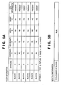
- Figs. 5A and 5B show an example of the block selection result.
- Fig. 5A shows block information of each extracted rectangular block.
- the block information includes an attribute, coordinates X and Y of a position, width W, height H, OCR information, and the like of each block. Attributes are given as numerical values 1 to 5: "1" indicates a text attribute; "2", a picture attribute; "3", a table attribute; "4", a line attribute; and "5", a photo attribute.
- the coordinates X and Y indicate the X- and Y-coordinates (those of the upper left corner) of a start point of each rectangular block of the input image
- the width W and height H indicate the width in the X-coordinate direction and the height in the Y-coordinate direction of the rectangular block
- the OCR information indicates the presence/absence of it.
- Fig. 5B shows input file information, which indicates the total number of rectangular blocks extracted by block selection.
- the block information for each rectangular block is used in vector conversion of the designated block. Based on the block information, the relative positional relationship between the vector-converted designated block and raster data can be specified, and the vector-converted block and raster data blocks can be combined without damaging the layout of the input image.
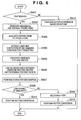
- Fig. 6 is a flowchart showing details of vector conversion (S306), which is the processing executed by the data processor 115 (or management PC 101).
- step S902 it is checked with reference to block information if a segment of interest is that of the text attribute (S901). If the segment of interest is that of the text attribute, the flow advances to step S902 to make character recognition using an arbitrary pattern matching scheme, thus obtaining a corresponding character code.
- vector conversion based on the outline of the image is executed (S912), as will be described in detail later.
- an observed feature vector obtained by converting the feature obtained from a character image into a several-ten-dimensional numerical value string is generated (S905).
- Feature vector extraction may use various known methods. For example, the following method may be used. That is, a character is segmented into meshes, lines which form the character in the meshes are counted as direction-dependent line elements, and a vector having dimensions as many as the number of meshes is defined as a feature vector.
- the observed feature vector is compared with feature vectors which are calculated for respective character types and are stored in a feature dictionary to calculate distances between these vectors (S906).
- the calculated distances are evaluated, and a character type with a smallest distance is determined as a recognition result (S907) Based on the evaluation results of the distances, the smallest distance is compared with a threshold. If the smallest distance is less than the threshold, it is determined that the similarity is high; otherwise, it is determined that the similarity is low (S908). If the smallest distance is equal to or larger than the threshold (if the similarity is low), the character image of interest is more likely to be erroneously recognized as another character with a similar shape.
- step S907 the recognition result in step S907 is not adopted, the character image is handled in the same manner as a line image, and the outline of the character image is vector-converted (S911). In other words, for the character image which has high probability of a recognition error, visually faithful outline vector data is generated.
- step S907 if the similarity is high, the recognition result in step S907 is adopted, and font information is output together with a character code, thus recognizing a character font (S909).
- a plurality of feature dictionaries as many as character types used in character recognition are prepared in correspondence with character shape types, i.e., font types, thus attaining font recognition.
- each character is converted into vector data with reference to the character code and font information obtained by the character recognition and font recognition using outline data prepared in advance in correspondence with'the character code and font information (S910).
- color image data a character color is extracted and is recorded together with vector data.
- character images included in the segment of the text attribute can be converted into vector data which have approximately faithful shapes, sizes, and colors.
- black pixel clusters are extracted, and their outlines are converted into vector data. Note that a segment of the photo attribute remains unchanged as image data without vector conversion.
- FIG. 7 is a view for explaining corner extraction processing in vector conversion.
- a corner is a point which corresponds to a maximal curvature, and whether or not a pixel Pi on a curve shown in Fig. 7 is a corner is determined as follows.
- the pixel Pi is defined as a starting point, and pixels Pi-k and Pi+k which are separated from the pixel Pi by the predetermined number k of pixels in two directions along the line image curve are connected by a line segment L.
- pixel arrays of the line image curve segmented by the corner are approximated by straight lines or curves. Approximation to a straight line is executed by a method of least squares or the like, and that to a curve uses a ternary spline function or the like. The pixel of the corner that segments pixel arrays becomes the start or terminal end of the approximated straight line or curve.
- the outline of a picture with an arbitrary shape can be vector-converted.
- an input image is a color image
- the color of a picture is extracted from the color image, and is recorded together with vector data.
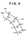
- Fig. 8 is a view for explaining processing for grouping outlines in vector conversion.
- an outside outline PRj When an outside outline PRj is close to an inside outline PRj+1 or another outside outline within a section of interest of outlines, two or three or more outlines are combined to express a line having a given width. For example, distances PQi between pixels Pi on the outline PRj+1 and pixels Qi on the outline PRj which have shortest distances from the pixels Pi are calculated. When variations of the distances PQi between a plurality of pixels are slight, the section of interest of the outlines PRj and PRj+1 is approximated by a straight line or curve along a point sequence of middle points Mi of line segments PQi. The width of the approximated straight line or curve along the point sequence of the middle points Mi can be set to be the average value of the distances PQi.
- a line or a table ruled line as a set of lines can be efficiently vector-converted by expressing them as a set of lines having a width.
- vector-converted partial lines are grouped for each picture object.
- Fig. 9 is a flowchart showing grouping processing of vector data generated by vector conversion, i.e., processing for grouping vector data for each picture object.
- Initial and terminal points of each vector data are calculated (S1401) to detect a picture element using the information of the initial and terminal points (S1402).
- the picture element is a closed picture formed by partial lines, and vectors are connected at common corner pixels serving as the initial and terminal ends upon detection. That is, a principle that vector groups forming closed shapes have vectors to be connected at their two ends is applied.
- step S1403 it is checked if another picture element or partial line exists in the picture element (S1403). If such picture element or partial line exists, steps S1401 and S1402 are recursively repeated. Then, these elements or lines are grouped to form a picture object (S1404). If no other picture element or partial line exists in the picture element, that picture element is defined as one picture object (S1405).
- FIG. 9 shows processing for only one picture object. If another picture object exists, the processing in Fig. 9 is repeated accordingly.
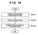
- Fig. 10 is a flowchart showing the detection processing of picture elements.
- Vectors which'do not have any vectors, two ends of which are not coupled to other vectors, are excluded from vector data to extract vectors which form a closed picture (S1501).
- one end point (initial or terminal point) of a vector of interest is set as a start point, and vectors are searched in a predetermined direction (e.g., clockwise). That is, the end point of the other vector is searched for at the other end point, and the closest end point within a predetermined distance is defined as an end point of a vector to be connected.
- a predetermined direction e.g., clockwise
- the end point of the other vector is searched for at the other end point, and the closest end point within a predetermined distance is defined as an end point of a vector to be connected.
- all the passed vectors are grouped as a closed picture which form one picture element (S1502).
- all vectors which form a closed picture present in the closed picture are recursively grouped.
- the initial point of a non-grouped vector is set as a start point to repeat the same processing.
- a vector (a vector to be connected to the closed picture) whose end point is close to the vectors grouped as the closed picture is detected, and the detected vector is grouped into that group (S1503).
- a picture block can be handled as an independently reusable picture object.
- the aforementioned vector conversion need not always be applied to the entire input image, but it often suffices to be applied to only the blocks designated by the user.
- the processing performance can be improved, and only desired blocks of the user can be efficiently vector-converted.
- vector data can be used in the next search processing, or only required blocks of an image can be efficiently reedited or reused.
- Fig. 11 is a flowchart showing the data file search processing. Assume that the input image is segmented into rectangular blocks shown in Fig. 4 as a result of the BS processing to obtain block information and input file information shown in Figs. 5A and 5B, and vector data of the blocks designated by the user are held.
- the attributes, coordinates, widths, heights, and the presence/absence of OCR information are recorded for six segments of blocks 1 to 6, and their attributes are respectively categorized into text, table, picture, text, table, and photo.
- the total number of blocks of the input file information indicates the total number of segments in the input image.
- segments are sorted in ascending order of coordinate X and are sorted in ascending order of coordinate Y if they have the same coordinate X.
- data files similar to the image of the designated blocks are searched for with reference to block information (or information similar to block information) of data files registered in the database server 105.
- Initialization is performed first to initialize a ratio of similarity (to be described later) to zero (S1101). It is checked if a data file which has a total number of blocks whose difference from the total number N of blocks of the input file information falls within a predetermined value range (N- ⁇ N ⁇ n ⁇ N+ ⁇ N) exists (S1102). If this condition is not met, the flow jumps to step S1114.
- the rectangular block information of that data file is compared with that of the input image, comparison of attributes (S1103), that of sizes (S1105), and that of the presence/absence of OCR information (S1107) are made in turn from upper segments. If the attributes of the segments match, a ratio of attribute similarity is updated (S1104). If the sizes match, a ratio of size similarity is updated (S1106). If the OCR information is present, two pieces of OCR information are compared (S1108), and a ratio of OCR information similarity is updated (S1109). It is checked if comparison of all the segments recorded in the rectangular block information of the input image is complete (S1110). If segments to be compared still remain, the flow returns to step S1103 to compare with the next segment.
- a ratio of total similarity of the data file to be compared is calculated on the basis of the ratio of attribute similarity, that of size similarity, and that of pointer similarity (S1111), and it is checked if the ratio of total similarity exceeds a pre-set threshold Th (S1112). If the ratio of total similarity exceeds the threshold Th, that data file is recorded as a candidate (S1113).
- step S1114 It is checked if comparison with all data files registered in the database server 105 is complete (S1114). If data files to be compared still remain, the flow returns to step S1101 to compare with the next data file. Upon completion of comparison of data files, the data files recorded as candidates are displayed as a list on the operation window in step S308.
- the ratio of attribute similarity is updated by calculating, e.g., a similarity + 1/N (N is the total number of blocks). It is determined that the sizes match when the size'difference falls within predetermined ranges W- ⁇ W ⁇ w ⁇ W+ ⁇ W and H- ⁇ H ⁇ h ⁇ H+ ⁇ H. Also, the ratio of size similarity is updated by defining 1 - (w - W)/W (W is the size of a segment of interest of the input image) as a ratio of size similarity of each segment, and calculating the average value of the ratios of size similarity of all segments.
- the ratio of OCR information similarity is updated by calculating a ratio of matching characters by comparing the character strings of the OCR information, and calculating the average value of the ratios of OCR similarity of all segments.
- the ratio of total similarity may be calculated by calculating the sum total of the ratios of similarity.
- predetermined weights may be given to the respective ratios of similarity, and their sum total may be calculated.
- vector data which are generated in step S306 for the blocks designated by the user, character code information acquired by the OCR processing, layout information indicating vertical/horizontal writing or the like, the number and layout of pictures by picture recognition, font information in a document by font recognition, and the like.
- Fig. 12 shows the format of intermediate data indicating the vector conversion result. Intermediate data is saved in a format called a document analysis output format (DAOF).
- DAOF document analysis output format
- the DAOF includes a header 1601, layout description data field 1602, character recognition description data field 1603, table description data field 1604, and image description data field 1605.
- the header 1601 holds information that pertains to the input image to be processed.
- the layout description data field 1602 holds information such as TEXT, TITLE, CAPTION, LINE, PICTURE, FRAME, TABLE, PHOTO, and the like indicating the attributes of rectangular segments in the input image, and position information of these rectangular segments.
- the character recognition description data field 1603 holds the character recognition result obtained by applying character recognition to the blocks designated by the user of the rectangular segments of the text attribute such as TEXT, TITLE, CAPTION, and the like.
- the table description data field 1604 holds details of the table structure of the rectangular segment of the table attribute.
- the image description data field 1605 holds image data segmented from the input image data in the rectangular segments of the picture attribute and line attribute.
- the image description data field 1605 of the vector-converted designated block holds a set of data indicating the internal structure, image shape, character code, and the like of a segment obtained by vector conversion.
- the image description data field 1605 holds the input image data itself for segments other than the designated blocks, which are not vector-converted.
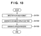
- Fig. 13 is a flowchart showing the conversion processing into the application data format.
- Data of the DAOF format is input (S1701), and a document structure tree as a basis of application data is generated (S1702). Real data in the DAOF are acquired based on the document tree structure to generate application data (S1703).
- Fig. 14 is a flowchart showing details of the document structure tree generation processing (S1703).
- the flow of processes transits from a microblock (single rectangular block) to a macroblock (a set of rectangular blocks).
- a microblock single rectangular block
- macroblock a set of rectangular blocks.
- rectangular block implies both a microblock and macroblock.
- Rectangular blocks are grouped for respective rectangular blocks on the basis of relevance in the vertical direction (S1801). Note that the processing shown in Fig. 14 is often repetitively executed. Immediately after the beginning of processing, determination is made for respective microblocks. Note that the relevance can be defined by features indicating if the distance between neighboring rectangular blocks is small, rectangular blocks have nearly the same block widths (heights in case of the horizontal direction), and so forth. Information of the distances, widths, heights, and the like can be extracted with reference to the DAOF.
- rectangular blocks T1 and T2 are juxtaposed in the horizontal direction in its uppermost portion.
- a horizontal separator S1 is present below the rectangular blocks T1 and T2, and rectangular blocks T3, T4, T5, T6, and T7 are present below the horizontal separator S1.
- the rectangular blocks T3, T4, and T5 are laid out in the vertical direction from top to down on the left half portion of a region below the horizontal separator S1.
- the rectangular blocks T6 and T7 are laid out from top to down on the right half portion of the region below the horizontal separator S1.
- step S1801 If grouping based on the relevance in the vertical direction is executed in step S1801, the rectangular blocks T3, T4, and T5 are combined into one group (rectangular block V1) and the rectangular blocks T6 and T7 are combined into another group (rectangular block V2).
- the groups V1 and V3 belong to an identical layer.
- the separator is an object having the line attribute in the DAOF, and has a function of explicitly separating blocks in application software.
- the region of the input image is divided into right and left regions to have the separator as a boundary in the layer to be processed.
- the example of Fig. 15 includes no vertical separator.
- rectangular blocks are grouped on the basis of relevance in the horizontal direction (S1804).
- the rectangular blocks T1 and T2 shown in Fig. 15 are combined into one group (rectangular block H1) and the rectangular blocks V1 and V2 are combined into one group (horizontal block H2).
- the groups H1 and H2 belong to an identical layer. Even in this case, immediately after the beginning of the processing, determination is made for respective microblocks.
- Fig. 15 includes the horizontal separator S1.
- Fig. 16 shows the document structure tree obtained from an image V0 shown in Fig. 15.
- the image V0 includes the groups H1 and H2, and the separator S1 in the uppermost layer, and the rectangular blocks T1 and T2 in the second layer belong to the group H1.
- the groups V1 and V2 in the second layer belong to the group H2.
- the rectangular blocks T3, T4, and T5 in the third layer belong to the group V1.
- the rectangular blocks T6 and T7 in the third layer belong to the'group V2.
- the group H1 Since the group H1 has the two rectangular blocks T1 and T2 in the horizontal direction, two columns are set, and the internal information (text as a character recognition result, image, and the like) of the rectangular block T1 is output to the first column (left column) with reference to the DAOF of T1. After that, the second column (right column) is selected, and the internal information of T2 is output. Then, the separator S1 is then output.
- the group H2 is selected. Since the group H2 has the two rectangular blocks V1 and V2 in the horizontal direction, two columns are set, and internal information is output to the first column (left column) in the order of the rectangular blocks T3, T4, and T5 of the group V1. After that, the second column (right column) is selected, and internal information is output to the selected column in the order of the rectangular blocks T6 and T7 of V2.
- the user designates one or a plurality of rectangular blocks automatically generated by the BS processing using the input unit 113 or the like as the blocks to be vector-converted.
- the present invention is not limited to this.
- the user may bound desired blocks on a document using a line marker pen or the like to designate blocks.
- additional information indicating a security level "vector conversion of segments or this document is NG” is often embedded in the entire document or segments (objects).
- the additional information is embedded using a barcode, two dimensional code®, digital watermark, background pattern, or the like.
- a method of using an application that appends additional information upon generation of a digital file a method of appending additional information by a device driver upon printing a document on a print sheet, and the like are available.
- the additional information designates restrictions on vector conversion, i.e., the availability of vector conversion, user specifying information or the security level of a user who is permitted to perform vector conversion, and the like.
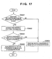
- Fig. 17 is a flowchart for explaining vector conversion that considers a case wherein a segment whose vector conversion is NG is included. This processing is executed by the management PC 101 in step S306 shown in Fig. 3.
- step S305 It is checked'if image data of the designated block segmented in step S305 includes additional information (S3601). If additional information is included, the additional information is extracted and interpreted (S3602). It is checked based on the interpretation result of the additional information and the user specifying information or security level acquired in step S300 if vector conversion of the image data of the designated block by the user is OK or NG (S3603). Of course, vector conversion of some segments may be NG independently of operators.
- the image data of the designated block is vector-converted (S3604).
- the image data of the designated block is partially vector-converted (S3605). This conversion will be described below.
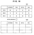
- Figs. 18 and 19 are views for explaining a method of partially vector-converting image data.
- attributes are determined for respective rectangular blocks by the block selection (BS) processing. For example, when a segment 1801 of a table attribute whose vector conversion is NG is present, vector data 1802 obtained by vector-converting only the frame and first row of the table is generated, as shown in Fig. 18. On the other hand, when a segment 1901 of a text attribute whose vector conversion is NG is present, vector data 1902 obtained by vector-converting only a character string for one line is generated, as shown in Fig. 19. Also, when a segment of a picture or line attribute whose vector conversion is NG is present, a part (a 1/10 upper left area, 100 x 100 upper right dots, or the like) of the relative area or absolute area of the segment is vector-converted. If necessary, further, a 1/10 lower left area, a 1/10 upper right area, and a 1/10 lower right area are vector-converted, and the vector-converted areas are used in the search to improve the accuracy of search.
- BS block selection
- a segment of a photo attribute is not vector-converted, as described above. However, when additional information that restricts vector conversion is appended to the segment of the photo attribute, and is the designated block, a partial image (a 1/9 central area) of the segment may be used in search.
- step S310 After it is determined in step S310 that a data file is specified, when that data file is acquired in step S311, vector data of a segment appended with additional information is inhibited from being used. Therefore, that segment is acquired as image data of a bitmap format or blank data.
- step S3603 If it is determined in step S3603 that vector conversion of that segment is OK, application data can be generated in step S312 using data which is vector-converted in step S3604.
- the user wants to generate reusable application data by vector-converting a document image.
- the segment (object) if there is a segment (object) whose vector conversion is restricted, the segment (object) is entirely or partially vector-converted according to that restriction, and can be used in data file search. Therefore, problems that information of segments that can be used in search is deficient, search is disturbed, a very long search time is required, and so forth, and a drop of the search precision can be eliminated while maintaining high security.
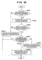
- Fig. 20 is a flowchart for explaining vector conversion that considers a case wherein a segment whose vector conversion is NG is included according to the second embodiment of the present invention. This processing is executed by the management PC 101 in step S306 shown in Fig. 3.
- steps S3601 to S3605 are the same as those in the first embodiment shown in Fig. 17.
- step S3603 if it is determined in step S3603 that additional information is found and vector conversion of image data of the designated block is NG, it is checked based on the interpretation result of the additional information and the user specifying information or security level of the operator if vector conversion upon search is OK (S3606). If it is determined that vector conversion upon search is NG, vector conversion is skipped; if it is determined partial vector conversion is OK, image data of the designated block is partially vector-converted to obtain data used in search (S3605); and if it is determined that vector conversion is OK, the entire image data of the designated block is vector-converted for the search purpose (S3607).
- vector conversion is permitted only for the search purpose, and the vector-converted vector data is inhibited from being stored in a data file for reuse. That is, vector conversion is limited to only the search purpose, and vector conversion for the purpose of generation of a data file and registration in a database is inhibited.
- the present invention can be applied to a system constituted by a plurality of devices (e.g., host computer, interface, reader, printer) or to an apparatus comprising a single device (e.g., copying machine, facsimile machine).
- devices e.g., host computer, interface, reader, printer
- apparatus comprising a single device (e.g., copying machine, facsimile machine).
- the object of the present invention can also be achieved by providing a storage medium storing program codes for performing the aforesaid processes to a computer system or apparatus (e.g., a personal computer), reading the program codes, by a CPU or MPU of the computer system or apparatus, from the storage medium, then executing the program.
- a computer system or apparatus e.g., a personal computer
- the program codes read from the storage medium realize the functions according to the embodiments, and the storage medium storing the program codes constitutes the invention.
- the storage medium such as a flexible disk, a hard disk, an optical disk, a magneto-optical disk, CD-ROM, CD-R, a magnetic tape, a non-volatile type memory card, and ROM can be used for providing the program codes.
- the present invention includes a case where an OS (operating system) or the like working on the computer performs a part or entire processes in accordance with designations of the program codes and realizes functions according to the above embodiments.
- the present invention also includes a case where, after the program codes read from the storage medium are written in a function expansion card which is inserted into the computer or in a memory provided in a function expansion unit which is connected to the computer, CPU or the like contained in the function expansion card or unit performs a part or entire process in accordance with designations of the program codes and realizes functions of the above embodiments.
- the storage medium stores program codes corresponding to the flowcharts described in the embodiments.
- a document image is read, and the read image is divided in accordance with the attributes of image regions. Designation of an image region whose image is to be vector-converted of the divided image regions is accepted, and additional information included in the designated image region is extracted. Search processing of a data file corresponding to the document image is controlled in accordance with the presence/absence of the additional information or the interpretation result of the additional information.
Landscapes
- Engineering & Computer Science (AREA)
- Library & Information Science (AREA)
- Theoretical Computer Science (AREA)
- Data Mining & Analysis (AREA)
- Databases & Information Systems (AREA)
- Physics & Mathematics (AREA)
- General Engineering & Computer Science (AREA)
- General Physics & Mathematics (AREA)
- Processing Or Creating Images (AREA)
- Information Retrieval, Db Structures And Fs Structures Therefor (AREA)
- Storing Facsimile Image Data (AREA)
- Image Processing (AREA)
Applications Claiming Priority (1)
| Application Number | Priority Date | Filing Date | Title |
|---|---|---|---|
| JP2005056213A JP4546291B2 (ja) | 2005-03-01 | 2005-03-01 | 画像処理装置およびその制御方法 |
Publications (1)
| Publication Number | Publication Date |
|---|---|
| EP1698988A1 true EP1698988A1 (en) | 2006-09-06 |
Family
ID=36579103
Family Applications (1)
| Application Number | Title | Priority Date | Filing Date |
|---|---|---|---|
| EP06110473A Withdrawn EP1698988A1 (en) | 2005-03-01 | 2006-02-28 | Image processing apparatus and its method |
Country Status (4)
| Country | Link |
|---|---|
| US (1) | US7747108B2 (ja) |
| EP (1) | EP1698988A1 (ja) |
| JP (1) | JP4546291B2 (ja) |
| CN (1) | CN100474880C (ja) |
Families Citing this family (21)
| Publication number | Priority date | Publication date | Assignee | Title |
|---|---|---|---|---|
| JP4181892B2 (ja) * | 2003-02-21 | 2008-11-19 | キヤノン株式会社 | 画像処理方法 |
| JP4921202B2 (ja) * | 2006-03-15 | 2012-04-25 | キヤノン株式会社 | ジョブ履歴管理システム、その制御方法、プログラム及び記憶媒体 |
| US9020811B2 (en) * | 2006-10-13 | 2015-04-28 | Syscom, Inc. | Method and system for converting text files searchable text and for processing the searchable text |
| JP5149570B2 (ja) * | 2006-10-16 | 2013-02-20 | キヤノン株式会社 | ファイル管理装置、ファイル管理装置の制御方法、及びプログラム |
| US8726178B2 (en) * | 2006-11-10 | 2014-05-13 | Ricoh Company, Ltd. | Device, method, and computer program product for information retrieval |
| US8244036B2 (en) * | 2007-01-24 | 2012-08-14 | Bluebeam Software, Inc. | Method for emphasizing differences in graphical appearance between an original document and a modified document with annotations |
| JP5233213B2 (ja) * | 2007-09-11 | 2013-07-10 | コニカミノルタビジネステクノロジーズ株式会社 | 画像処理装置、画像処理方法および画像処理プログラム |
| JP4926004B2 (ja) * | 2007-11-12 | 2012-05-09 | 株式会社リコー | 文書処理装置、文書処理方法及び文書処理プログラム |
| JP2009193187A (ja) * | 2008-02-13 | 2009-08-27 | Casio Comput Co Ltd | 画像検索方法、画像検索システム、画像検索端末および検索用サーバー |
| JP5100543B2 (ja) * | 2008-07-11 | 2012-12-19 | キヤノン株式会社 | 文書管理装置、文書管理方法、及びコンピュータプログラム |
| JP2010282611A (ja) * | 2009-05-07 | 2010-12-16 | Canon Inc | 情報処理装置、情報処理方法及びプログラム |
| JP5733907B2 (ja) * | 2010-04-07 | 2015-06-10 | キヤノン株式会社 | 画像処理装置、画像処理方法、コンピュータプログラム |
| US9165080B2 (en) * | 2010-12-22 | 2015-10-20 | International Business Machines Corporation | Systems and methods for creating scalable presence subscriptions in federated presence environments |
| JP2013246732A (ja) * | 2012-05-28 | 2013-12-09 | Toshiba Corp | 手書き文書検索装置、方法及びプログラム |
| EP2998934B1 (en) * | 2013-05-16 | 2020-08-05 | Sony Corporation | Image processing device, image processing method, and program |
| CN104462068B (zh) * | 2013-09-12 | 2017-11-07 | 北大方正集团有限公司 | 字符转换系统和字符转换方法 |
| US20190251349A1 (en) * | 2014-03-12 | 2019-08-15 | Gary L. Duerksen | System and method for object classification and sorting |
| US9224196B2 (en) * | 2014-03-12 | 2015-12-29 | ClearMark Systems, LLC | System and method for authentication |
| JP2016189507A (ja) * | 2015-03-30 | 2016-11-04 | 富士フイルム株式会社 | 画像処理装置、画像処理方法、プログラムおよび記録媒体 |
| US10412259B2 (en) * | 2015-09-30 | 2019-09-10 | Kyocera Document Solutions Inc. | Document reading apparatus and image forming apparatus |
| WO2018032253A1 (zh) * | 2016-08-15 | 2018-02-22 | 马岩 | 图片大数据的安全搜索方法及系统 |
Citations (5)
| Publication number | Priority date | Publication date | Assignee | Title |
|---|---|---|---|---|
| US4777651A (en) * | 1984-06-25 | 1988-10-11 | Tektronix, Inc. | Method of pixel to vector conversion in an automatic picture coding system |
| US5109431A (en) * | 1988-09-22 | 1992-04-28 | Hitachi, Ltd. | Pattern discrimination method and apparatus using the same |
| EP0932115A2 (en) * | 1998-01-23 | 1999-07-28 | Seiko Epson Corporation | Apparatus and method for pattern recognition |
| US20040090646A1 (en) * | 2002-09-19 | 2004-05-13 | Takashi Saitoh | Method, program, and apparatus for preventing a reproduction of an anti-copy document, and a medium storing the program |
| EP1447767A2 (en) | 2003-02-13 | 2004-08-18 | Canon Kabushiki Kaisha | Image document administration method |
Family Cites Families (6)
| Publication number | Priority date | Publication date | Assignee | Title |
|---|---|---|---|---|
| JP3017851B2 (ja) * | 1991-07-31 | 2000-03-13 | キヤノン株式会社 | 画像記憶装置 |
| JPH11272869A (ja) * | 1998-03-20 | 1999-10-08 | Nippon Steel Corp | ラスターデータ編集方法及びラスターデータ編集装置 |
| GB0120439D0 (en) * | 2001-08-22 | 2001-10-17 | Technologies Ltd H | Trading card or playing card system |
| JP4181892B2 (ja) * | 2003-02-21 | 2008-11-19 | キヤノン株式会社 | 画像処理方法 |
| JP2004326491A (ja) | 2003-04-25 | 2004-11-18 | Canon Inc | 画像処理方法 |
| JP2004334340A (ja) * | 2003-04-30 | 2004-11-25 | Canon Inc | 画像処理方法及び装置 |
-
2005
- 2005-03-01 JP JP2005056213A patent/JP4546291B2/ja not_active Expired - Fee Related
-
2006
- 2006-02-22 US US11/359,804 patent/US7747108B2/en not_active Expired - Fee Related
- 2006-02-28 EP EP06110473A patent/EP1698988A1/en not_active Withdrawn
- 2006-03-01 CN CNB2006100583284A patent/CN100474880C/zh not_active Expired - Fee Related
Patent Citations (5)
| Publication number | Priority date | Publication date | Assignee | Title |
|---|---|---|---|---|
| US4777651A (en) * | 1984-06-25 | 1988-10-11 | Tektronix, Inc. | Method of pixel to vector conversion in an automatic picture coding system |
| US5109431A (en) * | 1988-09-22 | 1992-04-28 | Hitachi, Ltd. | Pattern discrimination method and apparatus using the same |
| EP0932115A2 (en) * | 1998-01-23 | 1999-07-28 | Seiko Epson Corporation | Apparatus and method for pattern recognition |
| US20040090646A1 (en) * | 2002-09-19 | 2004-05-13 | Takashi Saitoh | Method, program, and apparatus for preventing a reproduction of an anti-copy document, and a medium storing the program |
| EP1447767A2 (en) | 2003-02-13 | 2004-08-18 | Canon Kabushiki Kaisha | Image document administration method |
Non-Patent Citations (1)
| Title |
|---|
| XIAOQING DING ET AL: "Document digitization technology and its application for digital library in China", DOCUMENT IMAGE ANALYSIS FOR LIBRARIES, 2004. PROCEEDINGS. FIRST INTERNATIONAL WORKSHOP ON PALO ALTO, CA, USA 23-24 JAN. 2004, LOS ALAMITOS, CA, USA,IEEE COMPUT. SOC, US, 23 January 2004 (2004-01-23), pages 46 - 53, XP010681119, ISBN: 0-7695-2088-X * |
Also Published As
| Publication number | Publication date |
|---|---|
| CN100474880C (zh) | 2009-04-01 |
| CN1829273A (zh) | 2006-09-06 |
| JP2006243942A (ja) | 2006-09-14 |
| JP4546291B2 (ja) | 2010-09-15 |
| US20060210162A1 (en) | 2006-09-21 |
| US7747108B2 (en) | 2010-06-29 |
Similar Documents
| Publication | Publication Date | Title |
|---|---|---|
| EP1698988A1 (en) | Image processing apparatus and its method | |
| US7961950B2 (en) | Image processing apparatus, method thereof, and its control method | |
| US7391917B2 (en) | Image processing method | |
| JP4557765B2 (ja) | 画像処理装置およびその方法 | |
| US7681121B2 (en) | Image processing apparatus, control method therefor, and program | |
| JP4251629B2 (ja) | 画像処理システム及び情報処理装置、並びに制御方法及びコンピュータプログラム及びコンピュータ可読記憶媒体 | |
| CN100448257C (zh) | 图像处理装置及其方法 | |
| US7542605B2 (en) | Image processing apparatus, control method therefor, and program | |
| JP3796500B2 (ja) | 画像処理装置及びその制御方法、プログラム | |
| JP4393161B2 (ja) | 画像処理装置及び画像処理方法 | |
| US9710524B2 (en) | Image processing apparatus, image processing method, and computer-readable storage medium | |
| JP4208780B2 (ja) | 画像処理システム及び画像処理装置の制御方法並びにプログラム | |
| US20060197928A1 (en) | Image processing apparatus and its method | |
| US20120250048A1 (en) | Image processing apparatus and image processing method | |
| JP3862694B2 (ja) | 画像処理装置及びその制御方法、プログラム | |
| JP2004326491A (ja) | 画像処理方法 | |
| JP4338189B2 (ja) | 画像処理システム及び画像処理方法 | |
| JP2008028716A (ja) | 画像処理方法及び装置 | |
| JP4323856B2 (ja) | 画像処理方法 | |
| JP2005149097A (ja) | 画像処理システム及び画像処理方法 | |
| JP2005149210A (ja) | 画像処理装置及びその制御方法、プログラム | |
| JP2007074140A (ja) | 画像処理装置及びその制御方法、画像処理システム | |
| JP2005149098A (ja) | 画像処理システム及び画像処理装置並びに画像処理方法 | |
| JP2004355315A (ja) | 画像処理方法 |
Legal Events
| Date | Code | Title | Description |
|---|---|---|---|
| PUAI | Public reference made under article 153(3) epc to a published international application that has entered the european phase |
Free format text: ORIGINAL CODE: 0009012 |
|
| AK | Designated contracting states |
Kind code of ref document: A1 Designated state(s): AT BE BG CH CY CZ DE DK EE ES FI FR GB GR HU IE IS IT LI LT LU LV MC NL PL PT RO SE SI SK TR |
|
| AX | Request for extension of the european patent |
Extension state: AL BA HR MK YU |
|
| 17P | Request for examination filed |
Effective date: 20070306 |
|
| AKX | Designation fees paid |
Designated state(s): DE ES FR GB IT NL |
|
| 17Q | First examination report despatched |
Effective date: 20071018 |
|
| STAA | Information on the status of an ep patent application or granted ep patent |
Free format text: STATUS: THE APPLICATION HAS BEEN WITHDRAWN |
|
| 18W | Application withdrawn |
Effective date: 20160204 |