EP1698457A1 - Decorative sheet, molded article, motor vehicle, and production method of molded article - Google Patents
Decorative sheet, molded article, motor vehicle, and production method of molded article Download PDFInfo
- Publication number
- EP1698457A1 EP1698457A1 EP20060010192 EP06010192A EP1698457A1 EP 1698457 A1 EP1698457 A1 EP 1698457A1 EP 20060010192 EP20060010192 EP 20060010192 EP 06010192 A EP06010192 A EP 06010192A EP 1698457 A1 EP1698457 A1 EP 1698457A1
- Authority
- EP
- European Patent Office
- Prior art keywords
- decorative sheet
- molded article
- layer
- resin material
- base member
- Prior art date
- Legal status (The legal status is an assumption and is not a legal conclusion. Google has not performed a legal analysis and makes no representation as to the accuracy of the status listed.)
- Granted
Links
- 238000004519 manufacturing process Methods 0.000 title claims description 17
- 229920005989 resin Polymers 0.000 claims abstract description 136
- 239000011347 resin Substances 0.000 claims abstract description 136
- 239000000463 material Substances 0.000 claims abstract description 102
- 229910052751 metal Inorganic materials 0.000 claims abstract description 99
- 239000002184 metal Substances 0.000 claims abstract description 99
- 238000005034 decoration Methods 0.000 claims abstract description 64
- 238000004040 coloring Methods 0.000 claims description 34
- ATJFFYVFTNAWJD-UHFFFAOYSA-N Tin Chemical compound [Sn] ATJFFYVFTNAWJD-UHFFFAOYSA-N 0.000 claims description 9
- 238000005304 joining Methods 0.000 claims description 9
- 229910052718 tin Inorganic materials 0.000 claims description 9
- 229910052782 aluminium Inorganic materials 0.000 claims description 6
- XAGFODPZIPBFFR-UHFFFAOYSA-N aluminium Chemical compound [Al] XAGFODPZIPBFFR-UHFFFAOYSA-N 0.000 claims description 6
- PCHJSUWPFVWCPO-UHFFFAOYSA-N gold Chemical compound [Au] PCHJSUWPFVWCPO-UHFFFAOYSA-N 0.000 claims description 6
- 229910052737 gold Inorganic materials 0.000 claims description 6
- 239000010931 gold Substances 0.000 claims description 6
- 238000010438 heat treatment Methods 0.000 claims description 6
- 229920005992 thermoplastic resin Polymers 0.000 claims description 6
- RYGMFSIKBFXOCR-UHFFFAOYSA-N Copper Chemical compound [Cu] RYGMFSIKBFXOCR-UHFFFAOYSA-N 0.000 claims description 5
- BQCADISMDOOEFD-UHFFFAOYSA-N Silver Chemical compound [Ag] BQCADISMDOOEFD-UHFFFAOYSA-N 0.000 claims description 5
- HCHKCACWOHOZIP-UHFFFAOYSA-N Zinc Chemical compound [Zn] HCHKCACWOHOZIP-UHFFFAOYSA-N 0.000 claims description 5
- 229910052802 copper Inorganic materials 0.000 claims description 5
- 239000010949 copper Substances 0.000 claims description 5
- 229910052738 indium Inorganic materials 0.000 claims description 5
- APFVFJFRJDLVQX-UHFFFAOYSA-N indium atom Chemical compound [In] APFVFJFRJDLVQX-UHFFFAOYSA-N 0.000 claims description 5
- 229910052709 silver Inorganic materials 0.000 claims description 5
- 239000004332 silver Substances 0.000 claims description 5
- 229910052725 zinc Inorganic materials 0.000 claims description 5
- 239000011701 zinc Substances 0.000 claims description 5
- 229910045601 alloy Inorganic materials 0.000 claims description 3
- 239000000956 alloy Substances 0.000 claims description 3
- 239000010410 layer Substances 0.000 description 224
- 238000000034 method Methods 0.000 description 23
- 239000012790 adhesive layer Substances 0.000 description 12
- 238000007493 shaping process Methods 0.000 description 12
- 238000003892 spreading Methods 0.000 description 12
- 230000007480 spreading Effects 0.000 description 12
- 239000007769 metal material Substances 0.000 description 10
- 239000002932 luster Substances 0.000 description 8
- 238000011156 evaluation Methods 0.000 description 6
- 239000004417 polycarbonate Substances 0.000 description 6
- 229920000515 polycarbonate Polymers 0.000 description 6
- 235000019589 hardness Nutrition 0.000 description 5
- 238000001579 optical reflectometry Methods 0.000 description 5
- PXHVJJICTQNCMI-UHFFFAOYSA-N Nickel Chemical compound [Ni] PXHVJJICTQNCMI-UHFFFAOYSA-N 0.000 description 4
- 238000009825 accumulation Methods 0.000 description 4
- 238000005452 bending Methods 0.000 description 4
- BASFCYQUMIYNBI-UHFFFAOYSA-N platinum Chemical compound [Pt] BASFCYQUMIYNBI-UHFFFAOYSA-N 0.000 description 4
- 230000008569 process Effects 0.000 description 4
- 230000002087 whitening effect Effects 0.000 description 4
- 239000000853 adhesive Substances 0.000 description 3
- 230000001070 adhesive effect Effects 0.000 description 3
- 229920003229 poly(methyl methacrylate) Polymers 0.000 description 3
- 229920000139 polyethylene terephthalate Polymers 0.000 description 3
- 239000005020 polyethylene terephthalate Substances 0.000 description 3
- 239000004926 polymethyl methacrylate Substances 0.000 description 3
- 239000004814 polyurethane Substances 0.000 description 3
- 229920005749 polyurethane resin Polymers 0.000 description 3
- 230000037303 wrinkles Effects 0.000 description 3
- VYZAMTAEIAYCRO-UHFFFAOYSA-N Chromium Chemical compound [Cr] VYZAMTAEIAYCRO-UHFFFAOYSA-N 0.000 description 2
- -1 Platinum Gold Tin Nickel Chemical compound 0.000 description 2
- 229910052804 chromium Inorganic materials 0.000 description 2
- 239000011651 chromium Substances 0.000 description 2
- 239000003086 colorant Substances 0.000 description 2
- 230000003292 diminished effect Effects 0.000 description 2
- 230000000694 effects Effects 0.000 description 2
- 229910052759 nickel Inorganic materials 0.000 description 2
- 239000003973 paint Substances 0.000 description 2
- 229910052697 platinum Inorganic materials 0.000 description 2
- 229920002635 polyurethane Polymers 0.000 description 2
- 238000007639 printing Methods 0.000 description 2
- 229920002050 silicone resin Polymers 0.000 description 2
- NIXOWILDQLNWCW-UHFFFAOYSA-M Acrylate Chemical compound [O-]C(=O)C=C NIXOWILDQLNWCW-UHFFFAOYSA-M 0.000 description 1
- 229920000178 Acrylic resin Polymers 0.000 description 1
- 239000004925 Acrylic resin Substances 0.000 description 1
- VGGSQFUCUMXWEO-UHFFFAOYSA-N Ethene Chemical compound C=C VGGSQFUCUMXWEO-UHFFFAOYSA-N 0.000 description 1
- 230000003796 beauty Effects 0.000 description 1
- 239000011230 binding agent Substances 0.000 description 1
- 239000011248 coating agent Substances 0.000 description 1
- 238000000576 coating method Methods 0.000 description 1
- 238000002485 combustion reaction Methods 0.000 description 1
- 238000005520 cutting process Methods 0.000 description 1
- 230000007547 defect Effects 0.000 description 1
- 230000002542 deteriorative effect Effects 0.000 description 1
- 125000000524 functional group Chemical group 0.000 description 1
- 238000001746 injection moulding Methods 0.000 description 1
- 229920001684 low density polyethylene Polymers 0.000 description 1
- 239000004702 low-density polyethylene Substances 0.000 description 1
- 238000012986 modification Methods 0.000 description 1
- 230000004048 modification Effects 0.000 description 1
- 238000000465 moulding Methods 0.000 description 1
- 230000000704 physical effect Effects 0.000 description 1
- 239000000049 pigment Substances 0.000 description 1
- 229920003023 plastic Polymers 0.000 description 1
- 239000004033 plastic Substances 0.000 description 1
- 229920000098 polyolefin Polymers 0.000 description 1
- 229920002803 thermoplastic polyurethane Polymers 0.000 description 1
Images


Classifications
-
- B—PERFORMING OPERATIONS; TRANSPORTING
- B32—LAYERED PRODUCTS
- B32B—LAYERED PRODUCTS, i.e. PRODUCTS BUILT-UP OF STRATA OF FLAT OR NON-FLAT, e.g. CELLULAR OR HONEYCOMB, FORM
- B32B15/00—Layered products comprising a layer of metal
- B32B15/04—Layered products comprising a layer of metal comprising metal as the main or only constituent of a layer, which is next to another layer of the same or of a different material
- B32B15/08—Layered products comprising a layer of metal comprising metal as the main or only constituent of a layer, which is next to another layer of the same or of a different material of synthetic resin
-
- B—PERFORMING OPERATIONS; TRANSPORTING
- B29—WORKING OF PLASTICS; WORKING OF SUBSTANCES IN A PLASTIC STATE IN GENERAL
- B29C—SHAPING OR JOINING OF PLASTICS; SHAPING OF MATERIAL IN A PLASTIC STATE, NOT OTHERWISE PROVIDED FOR; AFTER-TREATMENT OF THE SHAPED PRODUCTS, e.g. REPAIRING
- B29C45/00—Injection moulding, i.e. forcing the required volume of moulding material through a nozzle into a closed mould; Apparatus therefor
- B29C45/14—Injection moulding, i.e. forcing the required volume of moulding material through a nozzle into a closed mould; Apparatus therefor incorporating preformed parts or layers, e.g. injection moulding around inserts or for coating articles
- B29C45/14778—Injection moulding, i.e. forcing the required volume of moulding material through a nozzle into a closed mould; Apparatus therefor incorporating preformed parts or layers, e.g. injection moulding around inserts or for coating articles the article consisting of a material with particular properties, e.g. porous, brittle
- B29C45/14811—Multilayered articles
-
- B—PERFORMING OPERATIONS; TRANSPORTING
- B29—WORKING OF PLASTICS; WORKING OF SUBSTANCES IN A PLASTIC STATE IN GENERAL
- B29C—SHAPING OR JOINING OF PLASTICS; SHAPING OF MATERIAL IN A PLASTIC STATE, NOT OTHERWISE PROVIDED FOR; AFTER-TREATMENT OF THE SHAPED PRODUCTS, e.g. REPAIRING
- B29C51/00—Shaping by thermoforming, i.e. shaping sheets or sheet like preforms after heating, e.g. shaping sheets in matched moulds or by deep-drawing; Apparatus therefor
- B29C51/16—Lining or labelling
-
- B—PERFORMING OPERATIONS; TRANSPORTING
- B32—LAYERED PRODUCTS
- B32B—LAYERED PRODUCTS, i.e. PRODUCTS BUILT-UP OF STRATA OF FLAT OR NON-FLAT, e.g. CELLULAR OR HONEYCOMB, FORM
- B32B27/00—Layered products comprising a layer of synthetic resin
- B32B27/06—Layered products comprising a layer of synthetic resin as the main or only constituent of a layer, which is next to another layer of the same or of a different material
- B32B27/08—Layered products comprising a layer of synthetic resin as the main or only constituent of a layer, which is next to another layer of the same or of a different material of synthetic resin
-
- B—PERFORMING OPERATIONS; TRANSPORTING
- B32—LAYERED PRODUCTS
- B32B—LAYERED PRODUCTS, i.e. PRODUCTS BUILT-UP OF STRATA OF FLAT OR NON-FLAT, e.g. CELLULAR OR HONEYCOMB, FORM
- B32B7/00—Layered products characterised by the relation between layers; Layered products characterised by the relative orientation of features between layers, or by the relative values of a measurable parameter between layers, i.e. products comprising layers having different physical, chemical or physicochemical properties; Layered products characterised by the interconnection of layers
- B32B7/02—Physical, chemical or physicochemical properties
- B32B7/027—Thermal properties
-
- B—PERFORMING OPERATIONS; TRANSPORTING
- B32—LAYERED PRODUCTS
- B32B—LAYERED PRODUCTS, i.e. PRODUCTS BUILT-UP OF STRATA OF FLAT OR NON-FLAT, e.g. CELLULAR OR HONEYCOMB, FORM
- B32B7/00—Layered products characterised by the relation between layers; Layered products characterised by the relative orientation of features between layers, or by the relative values of a measurable parameter between layers, i.e. products comprising layers having different physical, chemical or physicochemical properties; Layered products characterised by the interconnection of layers
- B32B7/04—Interconnection of layers
- B32B7/12—Interconnection of layers using interposed adhesives or interposed materials with bonding properties
-
- B—PERFORMING OPERATIONS; TRANSPORTING
- B44—DECORATIVE ARTS
- B44C—PRODUCING DECORATIVE EFFECTS; MOSAICS; TARSIA WORK; PAPERHANGING
- B44C1/00—Processes, not specifically provided for elsewhere, for producing decorative surface effects
- B44C1/10—Applying flat materials, e.g. leaflets, pieces of fabrics
- B44C1/14—Metallic leaves or foils, e.g. gold leaf
-
- B—PERFORMING OPERATIONS; TRANSPORTING
- B29—WORKING OF PLASTICS; WORKING OF SUBSTANCES IN A PLASTIC STATE IN GENERAL
- B29C—SHAPING OR JOINING OF PLASTICS; SHAPING OF MATERIAL IN A PLASTIC STATE, NOT OTHERWISE PROVIDED FOR; AFTER-TREATMENT OF THE SHAPED PRODUCTS, e.g. REPAIRING
- B29C35/00—Heating, cooling or curing, e.g. crosslinking or vulcanising; Apparatus therefor
- B29C35/02—Heating or curing, e.g. crosslinking or vulcanizing during moulding, e.g. in a mould
- B29C35/08—Heating or curing, e.g. crosslinking or vulcanizing during moulding, e.g. in a mould by wave energy or particle radiation
- B29C35/0805—Heating or curing, e.g. crosslinking or vulcanizing during moulding, e.g. in a mould by wave energy or particle radiation using electromagnetic radiation
- B29C2035/0822—Heating or curing, e.g. crosslinking or vulcanizing during moulding, e.g. in a mould by wave energy or particle radiation using electromagnetic radiation using IR radiation
-
- B—PERFORMING OPERATIONS; TRANSPORTING
- B29—WORKING OF PLASTICS; WORKING OF SUBSTANCES IN A PLASTIC STATE IN GENERAL
- B29C—SHAPING OR JOINING OF PLASTICS; SHAPING OF MATERIAL IN A PLASTIC STATE, NOT OTHERWISE PROVIDED FOR; AFTER-TREATMENT OF THE SHAPED PRODUCTS, e.g. REPAIRING
- B29C2791/00—Shaping characteristics in general
- B29C2791/001—Shaping in several steps
-
- B—PERFORMING OPERATIONS; TRANSPORTING
- B29—WORKING OF PLASTICS; WORKING OF SUBSTANCES IN A PLASTIC STATE IN GENERAL
- B29C—SHAPING OR JOINING OF PLASTICS; SHAPING OF MATERIAL IN A PLASTIC STATE, NOT OTHERWISE PROVIDED FOR; AFTER-TREATMENT OF THE SHAPED PRODUCTS, e.g. REPAIRING
- B29C2791/00—Shaping characteristics in general
- B29C2791/004—Shaping under special conditions
- B29C2791/006—Using vacuum
-
- B—PERFORMING OPERATIONS; TRANSPORTING
- B29—WORKING OF PLASTICS; WORKING OF SUBSTANCES IN A PLASTIC STATE IN GENERAL
- B29C—SHAPING OR JOINING OF PLASTICS; SHAPING OF MATERIAL IN A PLASTIC STATE, NOT OTHERWISE PROVIDED FOR; AFTER-TREATMENT OF THE SHAPED PRODUCTS, e.g. REPAIRING
- B29C2791/00—Shaping characteristics in general
- B29C2791/004—Shaping under special conditions
- B29C2791/007—Using fluid under pressure
-
- B—PERFORMING OPERATIONS; TRANSPORTING
- B29—WORKING OF PLASTICS; WORKING OF SUBSTANCES IN A PLASTIC STATE IN GENERAL
- B29C—SHAPING OR JOINING OF PLASTICS; SHAPING OF MATERIAL IN A PLASTIC STATE, NOT OTHERWISE PROVIDED FOR; AFTER-TREATMENT OF THE SHAPED PRODUCTS, e.g. REPAIRING
- B29C2793/00—Shaping techniques involving a cutting or machining operation
- B29C2793/009—Shaping techniques involving a cutting or machining operation after shaping
-
- B—PERFORMING OPERATIONS; TRANSPORTING
- B29—WORKING OF PLASTICS; WORKING OF SUBSTANCES IN A PLASTIC STATE IN GENERAL
- B29C—SHAPING OR JOINING OF PLASTICS; SHAPING OF MATERIAL IN A PLASTIC STATE, NOT OTHERWISE PROVIDED FOR; AFTER-TREATMENT OF THE SHAPED PRODUCTS, e.g. REPAIRING
- B29C45/00—Injection moulding, i.e. forcing the required volume of moulding material through a nozzle into a closed mould; Apparatus therefor
- B29C45/14—Injection moulding, i.e. forcing the required volume of moulding material through a nozzle into a closed mould; Apparatus therefor incorporating preformed parts or layers, e.g. injection moulding around inserts or for coating articles
- B29C45/1418—Injection moulding, i.e. forcing the required volume of moulding material through a nozzle into a closed mould; Apparatus therefor incorporating preformed parts or layers, e.g. injection moulding around inserts or for coating articles the inserts being deformed or preformed, e.g. by the injection pressure
-
- B—PERFORMING OPERATIONS; TRANSPORTING
- B29—WORKING OF PLASTICS; WORKING OF SUBSTANCES IN A PLASTIC STATE IN GENERAL
- B29C—SHAPING OR JOINING OF PLASTICS; SHAPING OF MATERIAL IN A PLASTIC STATE, NOT OTHERWISE PROVIDED FOR; AFTER-TREATMENT OF THE SHAPED PRODUCTS, e.g. REPAIRING
- B29C51/00—Shaping by thermoforming, i.e. shaping sheets or sheet like preforms after heating, e.g. shaping sheets in matched moulds or by deep-drawing; Apparatus therefor
- B29C51/08—Deep drawing or matched-mould forming, i.e. using mechanical means only
-
- B—PERFORMING OPERATIONS; TRANSPORTING
- B29—WORKING OF PLASTICS; WORKING OF SUBSTANCES IN A PLASTIC STATE IN GENERAL
- B29C—SHAPING OR JOINING OF PLASTICS; SHAPING OF MATERIAL IN A PLASTIC STATE, NOT OTHERWISE PROVIDED FOR; AFTER-TREATMENT OF THE SHAPED PRODUCTS, e.g. REPAIRING
- B29C51/00—Shaping by thermoforming, i.e. shaping sheets or sheet like preforms after heating, e.g. shaping sheets in matched moulds or by deep-drawing; Apparatus therefor
- B29C51/10—Forming by pressure difference, e.g. vacuum
-
- B—PERFORMING OPERATIONS; TRANSPORTING
- B29—WORKING OF PLASTICS; WORKING OF SUBSTANCES IN A PLASTIC STATE IN GENERAL
- B29K—INDEXING SCHEME ASSOCIATED WITH SUBCLASSES B29B, B29C OR B29D, RELATING TO MOULDING MATERIALS OR TO MATERIALS FOR MOULDS, REINFORCEMENTS, FILLERS OR PREFORMED PARTS, e.g. INSERTS
- B29K2705/00—Use of metals, their alloys or their compounds, for preformed parts, e.g. for inserts
-
- B—PERFORMING OPERATIONS; TRANSPORTING
- B29—WORKING OF PLASTICS; WORKING OF SUBSTANCES IN A PLASTIC STATE IN GENERAL
- B29L—INDEXING SCHEME ASSOCIATED WITH SUBCLASS B29C, RELATING TO PARTICULAR ARTICLES
- B29L2009/00—Layered products
- B29L2009/003—Layered products comprising a metal layer
-
- B—PERFORMING OPERATIONS; TRANSPORTING
- B29—WORKING OF PLASTICS; WORKING OF SUBSTANCES IN A PLASTIC STATE IN GENERAL
- B29L—INDEXING SCHEME ASSOCIATED WITH SUBCLASS B29C, RELATING TO PARTICULAR ARTICLES
- B29L2031/00—Other particular articles
- B29L2031/30—Vehicles, e.g. ships or aircraft, or body parts thereof
- B29L2031/3005—Body finishings
-
- B—PERFORMING OPERATIONS; TRANSPORTING
- B32—LAYERED PRODUCTS
- B32B—LAYERED PRODUCTS, i.e. PRODUCTS BUILT-UP OF STRATA OF FLAT OR NON-FLAT, e.g. CELLULAR OR HONEYCOMB, FORM
- B32B2307/00—Properties of the layers or laminate
- B32B2307/70—Other properties
- B32B2307/738—Thermoformability
-
- B—PERFORMING OPERATIONS; TRANSPORTING
- B32—LAYERED PRODUCTS
- B32B—LAYERED PRODUCTS, i.e. PRODUCTS BUILT-UP OF STRATA OF FLAT OR NON-FLAT, e.g. CELLULAR OR HONEYCOMB, FORM
- B32B2311/00—Metals, their alloys or their compounds
- B32B2311/02—Noble metals
- B32B2311/04—Gold
-
- B—PERFORMING OPERATIONS; TRANSPORTING
- B32—LAYERED PRODUCTS
- B32B—LAYERED PRODUCTS, i.e. PRODUCTS BUILT-UP OF STRATA OF FLAT OR NON-FLAT, e.g. CELLULAR OR HONEYCOMB, FORM
- B32B2311/00—Metals, their alloys or their compounds
- B32B2311/02—Noble metals
- B32B2311/08—Silver
-
- B—PERFORMING OPERATIONS; TRANSPORTING
- B32—LAYERED PRODUCTS
- B32B—LAYERED PRODUCTS, i.e. PRODUCTS BUILT-UP OF STRATA OF FLAT OR NON-FLAT, e.g. CELLULAR OR HONEYCOMB, FORM
- B32B2311/00—Metals, their alloys or their compounds
- B32B2311/12—Copper
-
- B—PERFORMING OPERATIONS; TRANSPORTING
- B32—LAYERED PRODUCTS
- B32B—LAYERED PRODUCTS, i.e. PRODUCTS BUILT-UP OF STRATA OF FLAT OR NON-FLAT, e.g. CELLULAR OR HONEYCOMB, FORM
- B32B2311/00—Metals, their alloys or their compounds
- B32B2311/16—Tin
-
- B—PERFORMING OPERATIONS; TRANSPORTING
- B32—LAYERED PRODUCTS
- B32B—LAYERED PRODUCTS, i.e. PRODUCTS BUILT-UP OF STRATA OF FLAT OR NON-FLAT, e.g. CELLULAR OR HONEYCOMB, FORM
- B32B2311/00—Metals, their alloys or their compounds
- B32B2311/20—Zinc
-
- B—PERFORMING OPERATIONS; TRANSPORTING
- B32—LAYERED PRODUCTS
- B32B—LAYERED PRODUCTS, i.e. PRODUCTS BUILT-UP OF STRATA OF FLAT OR NON-FLAT, e.g. CELLULAR OR HONEYCOMB, FORM
- B32B2311/00—Metals, their alloys or their compounds
- B32B2311/24—Aluminium
-
- B—PERFORMING OPERATIONS; TRANSPORTING
- B32—LAYERED PRODUCTS
- B32B—LAYERED PRODUCTS, i.e. PRODUCTS BUILT-UP OF STRATA OF FLAT OR NON-FLAT, e.g. CELLULAR OR HONEYCOMB, FORM
- B32B2398/00—Unspecified macromolecular compounds
- B32B2398/20—Thermoplastics
-
- B—PERFORMING OPERATIONS; TRANSPORTING
- B32—LAYERED PRODUCTS
- B32B—LAYERED PRODUCTS, i.e. PRODUCTS BUILT-UP OF STRATA OF FLAT OR NON-FLAT, e.g. CELLULAR OR HONEYCOMB, FORM
- B32B2605/00—Vehicles
-
- Y—GENERAL TAGGING OF NEW TECHNOLOGICAL DEVELOPMENTS; GENERAL TAGGING OF CROSS-SECTIONAL TECHNOLOGIES SPANNING OVER SEVERAL SECTIONS OF THE IPC; TECHNICAL SUBJECTS COVERED BY FORMER USPC CROSS-REFERENCE ART COLLECTIONS [XRACs] AND DIGESTS
- Y10—TECHNICAL SUBJECTS COVERED BY FORMER USPC
- Y10T—TECHNICAL SUBJECTS COVERED BY FORMER US CLASSIFICATION
- Y10T428/00—Stock material or miscellaneous articles
- Y10T428/24—Structurally defined web or sheet [e.g., overall dimension, etc.]
- Y10T428/24479—Structurally defined web or sheet [e.g., overall dimension, etc.] including variation in thickness
- Y10T428/24612—Composite web or sheet
-
- Y—GENERAL TAGGING OF NEW TECHNOLOGICAL DEVELOPMENTS; GENERAL TAGGING OF CROSS-SECTIONAL TECHNOLOGIES SPANNING OVER SEVERAL SECTIONS OF THE IPC; TECHNICAL SUBJECTS COVERED BY FORMER USPC CROSS-REFERENCE ART COLLECTIONS [XRACs] AND DIGESTS
- Y10—TECHNICAL SUBJECTS COVERED BY FORMER USPC
- Y10T—TECHNICAL SUBJECTS COVERED BY FORMER US CLASSIFICATION
- Y10T428/00—Stock material or miscellaneous articles
- Y10T428/24—Structurally defined web or sheet [e.g., overall dimension, etc.]
- Y10T428/24802—Discontinuous or differential coating, impregnation or bond [e.g., artwork, printing, retouched photograph, etc.]
- Y10T428/24893—Discontinuous or differential coating, impregnation or bond [e.g., artwork, printing, retouched photograph, etc.] including particulate material
- Y10T428/24901—Discontinuous or differential coating, impregnation or bond [e.g., artwork, printing, retouched photograph, etc.] including particulate material including coloring matter
-
- Y—GENERAL TAGGING OF NEW TECHNOLOGICAL DEVELOPMENTS; GENERAL TAGGING OF CROSS-SECTIONAL TECHNOLOGIES SPANNING OVER SEVERAL SECTIONS OF THE IPC; TECHNICAL SUBJECTS COVERED BY FORMER USPC CROSS-REFERENCE ART COLLECTIONS [XRACs] AND DIGESTS
- Y10—TECHNICAL SUBJECTS COVERED BY FORMER USPC
- Y10T—TECHNICAL SUBJECTS COVERED BY FORMER US CLASSIFICATION
- Y10T428/00—Stock material or miscellaneous articles
- Y10T428/24—Structurally defined web or sheet [e.g., overall dimension, etc.]
- Y10T428/24802—Discontinuous or differential coating, impregnation or bond [e.g., artwork, printing, retouched photograph, etc.]
- Y10T428/24917—Discontinuous or differential coating, impregnation or bond [e.g., artwork, printing, retouched photograph, etc.] including metal layer
-
- Y—GENERAL TAGGING OF NEW TECHNOLOGICAL DEVELOPMENTS; GENERAL TAGGING OF CROSS-SECTIONAL TECHNOLOGIES SPANNING OVER SEVERAL SECTIONS OF THE IPC; TECHNICAL SUBJECTS COVERED BY FORMER USPC CROSS-REFERENCE ART COLLECTIONS [XRACs] AND DIGESTS
- Y10—TECHNICAL SUBJECTS COVERED BY FORMER USPC
- Y10T—TECHNICAL SUBJECTS COVERED BY FORMER US CLASSIFICATION
- Y10T428/00—Stock material or miscellaneous articles
- Y10T428/24—Structurally defined web or sheet [e.g., overall dimension, etc.]
- Y10T428/24942—Structurally defined web or sheet [e.g., overall dimension, etc.] including components having same physical characteristic in differing degree
- Y10T428/2495—Thickness [relative or absolute]
-
- Y—GENERAL TAGGING OF NEW TECHNOLOGICAL DEVELOPMENTS; GENERAL TAGGING OF CROSS-SECTIONAL TECHNOLOGIES SPANNING OVER SEVERAL SECTIONS OF THE IPC; TECHNICAL SUBJECTS COVERED BY FORMER USPC CROSS-REFERENCE ART COLLECTIONS [XRACs] AND DIGESTS
- Y10—TECHNICAL SUBJECTS COVERED BY FORMER USPC
- Y10T—TECHNICAL SUBJECTS COVERED BY FORMER US CLASSIFICATION
- Y10T428/00—Stock material or miscellaneous articles
- Y10T428/24—Structurally defined web or sheet [e.g., overall dimension, etc.]
- Y10T428/24942—Structurally defined web or sheet [e.g., overall dimension, etc.] including components having same physical characteristic in differing degree
- Y10T428/24992—Density or compression of components
-
- Y—GENERAL TAGGING OF NEW TECHNOLOGICAL DEVELOPMENTS; GENERAL TAGGING OF CROSS-SECTIONAL TECHNOLOGIES SPANNING OVER SEVERAL SECTIONS OF THE IPC; TECHNICAL SUBJECTS COVERED BY FORMER USPC CROSS-REFERENCE ART COLLECTIONS [XRACs] AND DIGESTS
- Y10—TECHNICAL SUBJECTS COVERED BY FORMER USPC
- Y10T—TECHNICAL SUBJECTS COVERED BY FORMER US CLASSIFICATION
- Y10T428/00—Stock material or miscellaneous articles
- Y10T428/31504—Composite [nonstructural laminate]
- Y10T428/31551—Of polyamidoester [polyurethane, polyisocyanate, polycarbamate, etc.]
- Y10T428/31605—Next to free metal
-
- Y—GENERAL TAGGING OF NEW TECHNOLOGICAL DEVELOPMENTS; GENERAL TAGGING OF CROSS-SECTIONAL TECHNOLOGIES SPANNING OVER SEVERAL SECTIONS OF THE IPC; TECHNICAL SUBJECTS COVERED BY FORMER USPC CROSS-REFERENCE ART COLLECTIONS [XRACs] AND DIGESTS
- Y10—TECHNICAL SUBJECTS COVERED BY FORMER USPC
- Y10T—TECHNICAL SUBJECTS COVERED BY FORMER US CLASSIFICATION
- Y10T428/00—Stock material or miscellaneous articles
- Y10T428/31504—Composite [nonstructural laminate]
- Y10T428/31678—Of metal
- Y10T428/31681—Next to polyester, polyamide or polyimide [e.g., alkyd, glue, or nylon, etc.]
Definitions
- the present invention relates to a decorative sheet used for decorating a molded article.
- the present invention also relates to a molded article provided with such a decorative sheet, a production method thereof, and a motor vehicle provided with such a molded article.
- the decorative sheet used in this technique is disclosed in Japanese Laid-Open Patent Publication No. 10-249999.
- the decorative sheet disclosed in this publication includes a base member and an ink layer formed by printing on a surface of the base member.
- the decorative sheet is attached to a molded article with an adhesive applied to the ink layer.
- the publication also describes that, instead of the ink layer, a metal layer formed of a metal material such as aluminum or chromium may be disposed on the surface of the base member.
- the molded article can be easily recycled as compared with the case of paint application using a coating material.
- such a decorative sheet can create a beautiful appearance which is different from the paint application, so that a decorative quality can be improved.
- a conventional decorative sheet including a metal layer is, however, suitable for the decoration of a molded article having a flat surface, but is not suitable for the decoration of a molded article having an uneven surface.
- a decorative sheet including a metal layer was attached to a molded article having an uneven surface (a hole for a screw, or a fixing structure for fixing to other members, for example), or a molded article having a deep drawing shape, the metal layer was broken and the color became locally pale, thereby deteriorating the decorative appearance.
- preferred embodiments of the present invention provide a decorative sheet preferably used for the decoration of a molded article having an uneven surface, and a molded article to which the decorative sheet is attached, and a production method thereof, and a motor vehicle provided with such a molded article.
- a decorative sheet includes a base member having a principal surface, and a decoration layer disposed on the principal surface of the base member, wherein the base member is formed from a first resin material, and the decoration layer includes a resin layer formed from a second resin material having a deflection temperature under load that is lower than a deflection temperature under load of the first resin material, and a metal layer which is in contact with the resin layer.
- the second resin material is a resin material having a deflection temperature under load of about 85°C or less measured under a load of about 0.45 MPa in accordance with ASTM D648.
- the first resin material is a thermoplastic resin material.
- the second resin material is a thermoplastic resin material.
- the resin layer is located at a position that is closer to the base member than the metal layer.
- the metal layer is located at a position that is closer to the base member than the resin layer.
- the decorative sheet according to the present invention further includes a coloring layer disposed on the decoration layer.
- a thickness of the base member is not less than about 100 ⁇ m and not greater than about 1,000 ⁇ m.
- the metal layer is formed of a metal having a Mohs' hardness of about 3 or less.
- the metal layer is formed from a material selected from a group of tin, aluminum, gold, copper, zinc, silver, and indium, and alloys thereof.
- a thickness of the metal layer is not less than about 0.2 ⁇ m and not greater than about 1.2 ⁇ m.
- two or more decoration layers are provided.
- a total thickness of the decoration layers is about 100 ⁇ m or less.
- the molded article according to various preferred embodiments of the present invention preferably includes a molded article body and the decorative sheet with the above-described structure joined to a surface of the molded article body.
- the molded article body has a deep drawing shape.
- the decorative sheet joined to the surface of the molded article body has a first portion having the largest thickness, and a second portion having a thickness which is approximately 70% or less of the thickness of the first portion.
- the second portion of the decorative sheet includes a third portion having a thickness which is about 50% or less of the thickness of the first portion.
- grain is formed on the surface of the molded article body.
- a surface of the metal layer has a shape reflecting the grain, and a surface of the decorative sheet opposite to the side of the molded article body is smoother than the surface of the metal layer.
- the motor vehicle according to another preferred embodiment of the present invention is provided with the molded article having the above-described structure.
- a production method of a molded article according to a preferred embodiment of the present invention includes the steps of preparing a molded article body and the decorative sheet having the above-described structure, heating the decorative sheet, and removing the air existing between the decorative sheet and the molded article body after overlapping the heated decorative sheet and the molded article body, thereby joining the decorative sheet to the molded article body.
- the decoration layer included in the decorative sheet according to preferred embodiments of the present invention preferably includes a resin layer formed from a second resin material having a deflection temperature under load that is lower than a deflection temperature under load of the first resin material for forming a base member, and a metal layer which is in contact with the resin layer.
- the resin layer formed from the second resin material is more easily deformed and spread than the base member with respect to a stress applied in shaping and joining, so that the metal layer which is in contact with the resin layer is suitably spread by following a contour and shape of the resin layer which is more easily spread than the base member. Therefore, the breakage of the metal layer is effectively prevented. As a result, a beautiful appearance can be attained.
- a decorative sheet suitably used for decorating a molded article having an uneven surface a molded article provided with such a decorative sheet and a production method thereof, and a motor vehicle provided with such a molded article are provided.
- FIG. 1 is a perspective view schematically showing a decorative sheet 10 according to a preferred embodiment of the present invention.
- FIG. 2 is a sectional view schematically showing the decorative sheet 10 according to a preferred embodiment of the present invention.
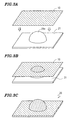
- FIGS. 3A, 3B, and 3C are views schematically showing one exemplary use of the decorative sheet 10 according to a preferred embodiment of the present invention.
- FIGS. 4A and 4B are sectional views schematically showing another preferred embodiment of the decorative sheet 10 according to the present invention.
- FIGS. 5A and 5B are views illustrating a condition of a decoration layer when the decorative sheet according to a preferred embodiment of the present invention is joined to a molded article body having a grain.
- FIG. 6A is a top view schematically showing a protruding portion which looks like a screw (an artificial screw), and 6B is a perspective view thereof.
- FIGS. 7A, 7B, and 7C are process sectional views schematically showing a production method of a molded article using the decorative sheet 10 according to a preferred embodiment of the present invention.
- FIGS. 8A, 8B, and 8C are process sectional views schematically showing a production method of a molded article using the decorative sheet 10 according to a preferred embodiment of the present invention.
- FIGS. 9A and 9B are process sectional views schematically showing another production method using the decorative sheet 10 according to a preferred embodiment of the present invention.
- FIG. 10 is a perspective view schematically showing another decorative sheet 10' according to a preferred embodiment of the present invention.
- FIG. 11 is a sectional view schematically showing the decorative sheet 10' according to a preferred embodiment of the present invention.
- FIG. 12 is a view schematically showing a condition where the decorative sheet 10' according to a preferred embodiment of the present invention reflects light.
- FIG. 13 is a view schematically showing a two-wheeled vehicle.
- FIGS. 1 and 2 schematically show a decorative sheet 10 according to a first preferred embodiment of the present invention.
- the decorative sheet 10 includes a base member 1 preferably formed from a resin material and a decoration layer 2 disposed on a principal surface 1a of the base member 1.
- the decoration layer 2 has a laminated structure in which a resin layer 3 formed from a resin material and a metal layer 4 formed from a metal material are laminated.
- the decoration layer 2 in this preferred embodiment further includes an adhesive layer 5 as shown in FIG. 2.
- the adhesive layer 5 attaches and fixes the decoration layer 2 to the principal surface 1a of the base member 1.
- the base member 1, the adhesive layer 5, the resin layer 3, and the metal layer 4 are laminated in this order.
- the resin layer 3 is located at a position that is closer to the base member 1 than the metal layer 4.
- An adhesive layer 6 shown by a chain line in FIG. 2 is applied on the decoration layer 2 when the decorative sheet 10 is to be attached.
- FIGS. 3A, 3B, and 3C An exemplary use of the decorative sheet 10 is shown in FIGS. 3A, 3B, and 3C.
- the decorative sheet 10 is attached to a surface of a molded article body 21, thereby decorating the molded article body 21, as shown in FIGS. 3A, 3B, and 3C.
- a combination of a metallic luster caused by a reflection of light from the metal layer 4 of the decoration layer 2 and a shine of the base member 1 positioned in an outermost surface of a molded article 20 provides a beautiful appearance.
- the molded article body 21 shown in FIG. 3A preferably has a substantially hemispherical (bowl-like) protruding portion 21a, and accordingly has an uneven surface. Therefore, when the decorative sheet 10 is attached, the decorative sheet 10 is spread so as to follow the unevenness. In order to preferably perform the spreading of the decorative sheet 10, typically, the decorative sheet 10 is attached after the decorative sheet 10 has been heated and softened.
- the inventors of the present invention performed various studies about the structure of the decorative sheet. As a result of the studies, the inventors of the present invention discovered that the breakage of the metal layer 4 was effectively prevented by forming the decoration layer 2 so as to have a layered structure, as shown in FIGS. 1 and 2, and by forming the resin layer 3 constituting the layered structure from a resin layer including a specific physical property. Thus, the inventors thought of and developed the present invention.
- the resin material for forming the resin layer 3 is preferably a resin material having a lower deflection temperature under load than that of a resin material for forming the base member 1.
- deflection temperature under load means a temperature at which a resin deflects by a predetermined distance under a predetermined load.
- first resin material the resin material for forming the base member 1
- second resin material the resin material for forming the resin layer 3
- the resin layer 3 is formed from the second resin material having a lower deflection temperature under load than that of the first resin material for forming the base member 1, the resin layer 3 is more easily deformed and spread against a stress applied in attachment (a bending stress or a tensile stress generated when the decorative sheet 10 is caused to follow the unevenness of the surface of the molded article body 21) than the base member 1. Therefore, the metal layer 4 which is in contact with the resin layer 3 follows the contour and shape of the surface of the resin layer 3 which is more easily spread than the base member 1, so as to be preferably spread during attaching. Therefore, in the decorative sheet 10 according to preferred embodiments of the present invention, the breakage of the metal layer 4 is effectively prevented. As a result, a beautiful appearance can be achieved.
- the second resin material for forming the resin layer 3 is preferably a resin material having a deflection temperature under load of about 85°C or less which is measured under a load of about 0.45 MPa in accordance with ASTM D648.
- the standards "ASTM D648" are the standards of a method of measuring a deflection temperature under load established by American Society for Testing and Materials. In the standards, a piece to be tested is heated under a specific bending load, and a temperature at which a predetermined amount of deflection occurs is determined to be a deflection temperature under load. When the deflection temperature under load of the second resin material exceeds about 85°C, the deforming and spreading properties of the resin layer 3 against the stress in attaching are sometimes insufficient.
- the second resin material is preferably a resin material having a deflection temperature under load of about 30°C or more measured under a load of about 0.45 MPa in accordance with ASTM D648. If the deflection temperature under load is lower than about 30°C, the resin layer 3 is too easily flowed due to the pressure in shaping (in attaching), so that defects such as wrinkles or breakage of the metal layer 4 may occur. When the deflection temperature under load of the second resin material is not lower than about 30°C and not higher than about 85°C, the effect that breakage of the metal layer 4 is effectively prevented can be more reliably achieved.
- thermoplastic resin material can be preferably used.
- a thermoplastic polyurethane resin can be preferably used.
- a silicone resin can be preferably used. More specifically, a polyurethane resin or a silicone resin which is prepared by using much of the materials having the number of functional group of 2, and which has a weight-average molecular weight of about 20,000 to about 100,000 can be preferably used.
- FIGS. 1 and 2 exemplarily show the structure in which one decoration layer 2 is disposed.
- a plurality of decoration layers 2 may be disposed.
- the metal layer 4 since the light reflectivity varies depending on the thickness thereof, a predetermined thickness is required for realizing a desired metallic luster. If the thickness of the metal layer 4 is excessive, a high spreading property cannot be obtained depending on the kind of a metal material in some cases.
- FIGS. 4A and 4B if a plurality of decoration layers 2 are disposed, a plurality of metal layers 4 contribute to the reflection of light, so that respective metal layers 4 can be thin. Therefore, a desired metallic luster can be realized, while the spreading property of the metal layers 4 is maintained to be high.
- the resin layer 3 is preferably located at a position that is closer to the base member 1 than the metal layer 4.
- the present invention is not limited to this structure.
- the metal layer 4 may be located at a position that is closer to the base member 1 than the resin layer 3. If the resin layer 3 is located at a position that is closer to the base member 1 than the metal layer 4, a minute structure formed on the surface of the molded article body can be reflected in the appearance.
- FIGS. 5A and 5B this point will be described in more detail.
- FIG. 5A shows a condition before the decorative sheet 10 is attached to the molded article body 21.
- FIG. 5B shows a condition after the decorative sheet 10 is attached to the molded article body 21.
- the attachment of the decorative sheet 10 is performed at a temperature that is substantially equal to or higher than the deflection temperature under load of the second resin material.
- a minute projections-and-depressions structure which looks like wrinkles i.e., so-called "grain" is formed.
- the grain is typically a projections-and-depressions structure in which the maximum distance Rmax from the deepest point to the highest point is not less than about 300 ⁇ m and not more than about 1,000 ⁇ m.
- the grain in this preferred embodiment has a maximum distance Rmax of about 500 ⁇ m formed by using a vacuum/pressure forming method.
- the metal layer 4 is closer to the molded article body 21 than the resin layer 3. Accordingly, as shown in FIG. 5B, the metal layer 4 is deformed so as to have a form reflecting the form of the grain, and light is reflected from the metal layer 4 which is deformed in this way. Therefore, it is possible to reflect the grain in the appearance. At this time, the surface of the resin layer 3 on the side of the metal layer 4 is deformed by following the deformation of the metal layer 4.
- the second resin material is in a condition where it can sufficiently deform (plastic deformation)
- the surface thereof on the side of the base member 1 is not deformed. That is, the resin layer 3 positioned between the metal layer 4 and the base member 1 functions as a cushion for reducing the influence of the deformation of the metal layer 4 to the base member 1. Accordingly, the form of the grain is not reflected on the principal surface 1a or a back surface (a surface opposite to the principal surface 1a) of the base member 1, and the form of the back surface (functioning as a surface of the decorative sheet 10) of the base member 1 is smoother than the surface of the metal layer 4. Thus, the luster of the base member 1 is not deteriorated. Therefore, a tasteful appearance in which the grain-like wrinkle is reflected, and having a high luster can be attained.
- Table 1 shows the results of appearance evaluation when the deflection temperature under load of the second resin material is varied.
- Table 1 shows the case where a decorative sheet 10 including a base member 1, preferably formed from polycarbonate, having a thickness of about 500 ⁇ m, a metal layer 4, preferably formed from tin, having a thickness of about 1 ⁇ m, and a resin layer 3 having a thickness of about 25 ⁇ m is attached to a surface of a molded article body 21 on which a grain with a difference in height between the deepest point and the highest point of about 0.2 mm is formed at a shaping temperature of about 195°C.
- Table 1 evaluates whether the grain formed on the surface of the molded article body 21 can be reflected in the appearance or not.
- Table 1 also evaluates the whitening of the decorative sheet 10.
- Table 1 Second Resin Material Deflection Temperature under Load (°C) Reflection of Grain Remarks UP 35 With Grain 50 With Grain 90 Thin Grain PVC 50 With Grain 90 Without Grain EVA 60 With Grain PP 110 Without Grain Whitening PET 80 With Grain Whitening PMMA 70 With Grain 100 Without Grain LDPE 30 With Grain Whitening
- the deflection temperature under load of the second resin material exceeds about 85°C, the grain becomes weak or does not appear. This is because if the deflection temperature under load of the second resin material exceeds about 85°C, the function of the resin layer 3 of absorbing the stress caused by the deformation of the metal layer 4 is deteriorated, so that a deformation failure of the metal layer 4 may occur. For this reason, it is preferred that the deflection temperature under load of the second resin material be about 85°C or less. As described above, in order to prevent the excess flow of the resin layer 3 in shaping, it is preferred that the deflection temperature under load of the second resin material be about 30°C or more. Accordingly, when the deflection temperature under load of the second resin material is not less than about 30°C and not more than about 85°C, the resin layer 3 functions as a stress absorbing layer in just proportion for the deformation of the metal layer 4.
- the metal layer 4 be formed from a metal material having a high spreading property (a high extensibility).
- the metal layer 4 formed from a metal material having a high spreading property may easily deformed as shown in FIG. 5B.
- the metal layer 4 may preferably be formed from a metal material having a high spreading property.
- a material with a high spreading property specifically, tin, aluminum, gold, copper, zinc, silver, and indium, and alloys thereof may be used to form the metal layer 4.
- Table 2 shows the results of appearance evaluations when the material of the metal layer 4 is changed.
- Table 2 shows the case where two decoration layers 2 are disposed as shown in FIG. 4A.
- Table 2 also shows the case where a decorative sheet 10 includes a base member 1, formed from polycarbonate, having a thickness of about 500 ⁇ m, a resin layer 3, formed from polyurethane, having a thickness of about 18 ⁇ m, and an adhesive layer 5, formed from polyurethaneacrylate, having a thickness of about 1.5 ⁇ m.
- Table 2 evaluates whether the grain formed on the surface of the molded article body 21 can be observed in the appearance or not.
- Table 2 Thickness of Metal Layer ( ⁇ m) Platinum Gold Tin Nickel 0.5 With Grain With Grain With Grain Without Grain 1 Without Grain With Grain With Grain Without Grain 2 Without Grain With Grain With Grain Without Grain Without Grain
- the grain can be reflected in all of the cases of about 0.5 ⁇ m, about 1 ⁇ m, and about 2 ⁇ m in thickness.
- the material is platinum, the thickness is required to be about 0.5 ⁇ m or less in order to reflect the grain.
- the material is nickel, the grain cannot be reflected in all of the cases of about 0.5 ⁇ m, about 1 ⁇ m, and about 2 ⁇ m in thickness.
- the preferred materials of the metal layer 4 are not limited to those exemplarily described in the above description. Generally, a softer metal has a higher spreading property. If metal having Mohs' hardness of about 3 or less is used, the spreading property of the metal layer 4 can be sufficiently high.
- Table 3 shows Mohs' hardnesses of various kinds of metal materials. As is seen from Table 3, all of tin, aluminum, gold, copper, zinc, silver, and indium have Mohs' hardness of about 3 or less, so that they can be preferably used as the material for the metal layer 4.
- the thickness of the metal layer 4 is preferably not less than about 0.2 ⁇ m and not more than about 1.2 ⁇ m. If the thickness of the metal layer 4 is less than about 0.2 ⁇ m, the light reflectivity of the metal layer 4 is low, and the color may sometimes be weak. If the thickness of the metal layer 4 exceeds about 1.2 ⁇ m, a sufficiently high spreading property cannot be obtained, in some cases. Table 4 shows the results of appearance evaluation when the thickness of the metal layer 4 formed from tin and the accumulation number of decoration layers 2 are varied.
- the total thickness of the decoration layers 2 when the accumulation number of decoration layers 2 is relatively small, and the total thickness of the decoration layers 2 is relatively small, good evaluation results can be obtained in the thickness range of about 0.2 ⁇ m to about 1.2 ⁇ m of the metal layer 4.
- the accumulation number of decoration layers 2 when the accumulation number of decoration layers 2 is relatively large, and the total thickness of the decoration layers 2 is relatively large, the grain gets thinner, and it is difficult to observe the grain.
- the total thickness of the decoration layers 2 exceeds about 100 ⁇ m, the grain is remarkably thin. If the total thickness is about 200 ⁇ m, the grain is hardly observed. Accordingly, in order to reflect the grain in the appearance, it is preferred that the total thickness of the decoration layers 2 be about 100 ⁇ m or less.
- a thermoplastic resin material can be preferably used.
- polycarbonate can be preferably used.
- the deflection temperature under load of polycarbonate is about 140°C to about 200°C.
- PMMA polymethyl methacrylate
- PET polyethylene terephthalate
- Rigidity as a sheet member is required for the base member 1. Accordingly, it is preferred that the first resin material be selected in view of this point. Since the base member 1 is positioned on the outermost surface of the molded article 20 after the attachment, the base member 1 is preferably superior in weather resistance and resistance to damage. Alternatively, on a surface of the base member 1 opposite to the side of the decoration layer 2, a protection layer which is superior in weather resistance and resistance to damage may be formed.
- the thickness of the base member 1 is preferably not lower than about 100 ⁇ m and not less than about 1,000 ⁇ m. If the thickness of the base member 1 is less than about 100 ⁇ m, it is difficult to deal the base member 1 as a sheet, and the strength is not sufficient, so that the base member 1 may be broken during the attachment. If the thickness of the base member 1 exceeds about 1,000 ⁇ m, the following property for the surface of the molded article body 21 may sometimes be deteriorated.
- Table 5 shows the results of appearance evaluation when the thickness of the base member 1 and the accumulation number of decoration layers 2 are varied.
- Table 5 shows the case where the base member 1 is formed from polycarbonate, and one to six decoration layers 2 each including the resin layer 3 having a thickness of about 18 ⁇ m, the metal layer 4 having a thickness of about 0.5 ⁇ m, and the adhesive layer 5 having a thickness of about 1.5 ⁇ m are disposed.
- a protruding portion (an artificial screw) 21b having a height of about 5 mm, which looks like a screw as shown in FIGS. 6A and 6B, is formed on the surface of the molded article body, and it is evaluated whether the protruding portion 21b can be observed well or not after the attachment of the decorative sheet 10.
- the base member 1 As shown in Table 5, as the base member 1 becomes thicker, it becomes difficult to observe the artificial screw 21b. This is because, as the base member 1 becomes thicker, the following property of the decorative sheet 10 to the artificial screw 21b becomes deteriorated. Accordingly, in view of the point that the ability to follow the unevenness of the surface of the molded article body 21 is increased, thereby obtaining good appearance, it is preferred that the base member 1 be thin. Specifically, the base member 1 preferably has a thickness of about 1,000 ⁇ m or less. However, as described above, if the base member 1 is too thin, it is difficult to handle the base member 1 as a sheet, or the strength is insufficient, thereby causing the base member 1 to broken during the attaching process. It is preferred that the thickness of the base member 1 be determined in view of these points. Thus, the thickness of the base member 1 is preferably about 100 ⁇ m or more.
- the total thickness of the decoration layers 2 is about 100 ⁇ m or less. As shown in Table 5, if the total thickness of the decoration layers 2 exceeds about 100 ⁇ m, it is difficult to observe the artificial screw 21. Accordingly, also in view of the property of being able to follow the unevenness which is larger than the grain (a head portion of a screw, or a step or roughness included in the molded article body), it is preferred that the total thickness of the decoration layer 2 is about 100 ⁇ m or less.
- the adhesive layer 5 for attaching the decoration layer 2 to the base member As a material of the adhesive layer 5 for attaching the decoration layer 2 to the base member 1, polyurethane acrylate, polyurethane, or acrylic resin, for example, can be used. The materials are not limited to these, but a material which can attach the resin layer 3 or the metal layer 4 to the base member 1 may be used.
- the thickness of the adhesive layer 5 is preferably about 1 ⁇ m to about 20 ⁇ m, for example.
- a molded article body 21 and a decorative sheet 10 are prepared.
- the molded article body 21 may be formed from a resin material, formed from a metal material, or formed from other materials.
- the molded article body 21 can be prepared using a known technique. If a resin material is used, the molded article body 21 can be prepared by injection molding, for example.
- the decorative sheet 10 can be fabricated by using the above-described materials by a known technique.
- the decorative sheet 10 can be prepared in the following manner. On a film as a resin layer 3, a metal material is vapor deposited, so as to form a metal layer 4, thereby forming a decoration layer 2. A required number of decoration layers 2 are laminated on a principal surface 1a of a base member 1, thereby fabricating the decorative sheet 10.
- an adhesive can be used, for example.
- the molded article body 21 is placed on a supporting device 30.
- the decorative sheet 10 is fixed by a holding device 32 so that the decorative sheet 10 is positioned above the molded article body 21.
- an adhesive 6 is applied on the decoration layer 2 of the decorative sheet 10.
- the decorative sheet 10 is heated by using a heater 34, thereby softening the decorative sheet 10.
- the decorative sheet 10 is heated up to a temperature which is higher than the deflection temperature under load of the second resin material for forming the resin layer 3.
- the decorative sheet 10 is heated up to a temperature which is higher than the deflection temperature under load of the first resin material for forming the base member 1.
- the decorative sheet 10 be heated to temperatures in the range of about (T DUL -40)°C to about (T DUL +20)°C.
- the heater 34 is preferably a far infrared heater, for example.
- the air existing between the decorative sheet 10 and the molded article body 21 is removed, thereby joining the decorative sheet 10 to the molded article body 21, as shown in FIG. 8A.
- a difference in pressure occurs between a side of the decorative sheet 10 facing the molded article body 21 and the other side thereof.
- the decorative sheet 10 is pressed against the molded article body 21 with a substantially uniform pressure. Therefore, the joining of the decorative sheet 10 and the molded article body 21 is suitably performed.
- compressed air is supplied to a space expanding on the side opposite to the molded article body 21 with respect to the decorative sheet 10, thereby causing a larger difference in pressure.
- the overlapping of the decorative sheet 10 onto the molded article body 21 is performed by lowering the holding device 32 by an elevator apparatus, for example.
- the removal of the air between the decorative sheet 10 and the molded article body 21 is preferably performed by using a vacuum pump, for example, thereby sucking the air through an opening portion 30a disposed in the supporting device 30.
- the supply of the compressed air is preferably performed by a compressor, for example.
- the joining of the decorative sheet 10 to the molded article body 21 i.e., the shaping of the decorative sheet 10) can be performed in a very short period of time (in less than one second, for example).
- the decorative sheet 10 according to preferred embodiments of the present invention is used, so that even if the decorative sheet 10 is shaped and joined in such a short time, no breakage occurs in the metal layer 4, and the beauty in appearance is not deteriorated.
- the decorative sheet 10 is not limited to the production method in which the decorative sheet 10 is joined to the molded article body 21 which is already molded as described with reference to FIGS. 7A to 7C and FIGS. 8A to 8C (referred to as a "film on” method), but can be applied to other production methods.
- FIGS. 9A and 9B schematically show a production method referred to as a "film insert" method.
- a decorative sheet 10 is shaped in a vacuum along a surface of a female die 40.
- uncounted numbers of opening portions are disposed in the surface of the female die 40. Through the opening portions, the air existing between the female die 40 and the decorative sheet 10 is exhausted, thereby performing the vacuum shaping of the decorative sheet 10.
- a resin material is injected under pressure through a resin injecting port 42a of a male die 42, so as to molding the molded article body 21, and to join the molded article body 21 and the decorative sheet 10.
- the decorative sheet 10 can be used in the film insert method.
- the film insert method requires both of the female die 40 and the male die 42. That is, two expensive dies are always required. This necessarily results in increases of the production cost.
- the surface of the decorative sheet 10 is in contact with the surface of the female die 40 which includes openings for evacuation, so that projections and depressions are formed on the surface of the decorative sheet 10.
- the process step of injecting the resin material under pressure is required.
- the decorative sheet 10 is required to have high heat resistance and high pressure resistance.
- the resin material is injected under pressure, a large force is locally applied to the decorative sheet 10.
- the decorative sheet 10 may be broken in some cases.
- the molded article body 21 is limited to be formed from the resin material.
- the film on method described with reference to FIGS. 7A to 7C and 8A to 8C two dies are not necessarily required, so that the production cost can be reduced.
- the joining of the decorative sheet 10 is performed by removing the air existing between the decorative sheet 10 and the molded article body 21, so that a substantially uniform force can be applied to the entire surface of the decorative sheet 10. Thus, the breakage of the decorative sheet 10 can be prevented.
- the surface of the decorative sheet 10 on the side of the base member 1 is not required to be in contact with the openings for evacuation, so that any projections and depressions are not formed on the surface of the decorative sheet 10.
- the beautiful appearance is not diminished or deteriorated.
- the process step of injecting the resin under pressure is not required, so that the joining and the shaping of the decorative sheet 10 can be performed at a lower temperature and at a lower pressure as compared with the film insert method.
- the decorative sheet 10 with lower temperature resistance and pressure resistance can be used.
- the film on method not only the molded article body 21 formed from the resin material, but also the molded article body 21 formed from a metal material or other materials can be decorated.
- FIGS. 10 and 11 a decorative sheet 10' in this preferred embodiment will be described.
- identical reference numerals are used for designating substantially the same components as those of the decorative sheet 10 in the first preferred embodiment, and the descriptions thereof are omitted.
- the decorative sheet 10' is different from the decorative sheet 10 in the first preferred embodiment in that the decorative sheet 10' includes a coloring layer 7 disposed on the decoration layer 2.
- the decoration layer 2 has a structure in which the metal layer 4 is disposed in a position closer to the base member 1 than the resin layer 3.
- the coloring layer 7 is formed on the resin layer 3.
- the decoration layer 2 also has a laminated structure including the resin layer 3 and the metal layer 4.
- the resin layer 3 is formed from the second resin material having the deflection temperature under load lower than the deflection temperature under load of the first resin material for forming the base member 1, so as to achieve the effect of preventing breakage of the metal layer 4.
- the coloring layer 7 is additionally disposed on the decoration layer 2. As shown in FIG. 12, light entering in the inside of the decorative sheet 10' is reflected from both of the metal layer 4 and the coloring layer 7. Accordingly, the decorative sheet 10' can exhibit colors having both a metallic luster generated by the metal layer 4 and the coloring generated by the coloring layer 7, that is, metallic colors having a metal-like appearance.
- the coloring layer 7 for example, ink including a resin material as a binder, and pigment dispersed in the resin material can be used.
- the coloring layer 7 can be formed by printing with such ink.
- the material for the coloring layer 7 is preferably superior in heat resistance and resistance to bending.
- the ink disclosed in Japanese Laid-Open Patent Publication No.2002-275405 has superior heat resistance and resistance to bending, so that the ink can be suitably used as the material for the coloring layer 7.
- Table 6 shows the results of appearance evaluation when the thickness of the coloring layer 7 and the accumulated number of decoration layers 2 are varied.
- ⁇ indicates very good coloring
- ⁇ indicates good coloring
- ⁇ indicates no good coloring.
- Table 6 shows the case where a polyurethane resin is used as the material for the resin layer 3, tin is used as the material for the metal layer 4, and ink of dark green is used as the material for the coloring layer 7.
- the coloring layer 7 As shown in Table 6, as the thickness of the coloring layer 7 is increased, the coloring becomes better. This is because as the thickness of the coloring layer 7 is increased, the light reflectivity of the coloring layer 7 is increased. Accordingly, in order to improve the coloring, it is preferred that the coloring layer 7 be thicker.
- the coloring is not good when one decoration layer 2 is disposed. This is because the light reflectivity of the metal layer 4 is too low to sufficiently obtain a metallic luster. Also in the case where five decoration layers 2 are disposed, the coloring is not good. This is because the light reflectivity of the plurality of metal layers 4 is too high, so that the amount of light which reaches the coloring layer 7 is small. Therefore, in the case where the coloring layer 7 is disposed on the decoration layers 2 as in this preferred embodiment, it is preferred that the number of decoration layers 2 and the thickness of the metal layer 4 be appropriately determined so that the metallic luster by the metal layer 4 is sufficiently obtained, and a sufficient amount of light reaches the coloring layer 7.
- the metal layer 4 is located at a position closer to the base member 1 than the resin layer 3, and the coloring layer 7 is formed on the resin layer 3.
- the resin layer 3 may be disposed at a location that is closer to the base member 1 than the metal layer 4, and the coloring layer 7 may be formed on the metal layer 4.
- the material of the coloring layer 7 in order to improve the adhesion between the coloring layer 7 and the decoration layer 2, the metal layer 4 is preferably located at position that is closer to the base member 1 than the resin layer 3, and the coloring layer 7 is preferably formed on the resin layer 3.
- the decorative sheet according to the present invention can effectively prevent the breakage of the metal layer during shaping (in joining to the molded article body), so that the decorative sheet can be suitably used for decorating a molded article body having an uneven surface.
- the decorative sheet according to preferred embodiments of the present invention can be suitably used in the case where a molded article body has a fixing structure for fixing to other members or has an uneven spot such as a screw hole in the surface, in the case where a molded article body has a deep drawing shape, and in other cases.
- the "deep drawing shape” is a shape having a high ratio H/D of draw depth H to draw diameter D. Specifically, the shape has the ratio H/D of about 0.75 or more.
- the decorative sheet joined to the surface of the molded article body having the deep drawing shape typically includes a portion having a thickness which is about 70% or less of the thickness of a portion having the largest thickness. In many cases, the decorative sheet includes a portion having a thickness which is about 50% or less of the thickness of the portion having the largest thickness.
- the molded article decorated by using the decorative sheet according to preferred embodiments of the present invention is suitably used for the interior or the exterior of motor vehicles.
- the molded article is suitably used as a tank cover 51, a front fender 52, and a tail cowl 53 of a motorbike 50 shown in FIG. 13.
- the term "motor vehicles” widely indicates mobile conveyances or machines for transporting passengers or merchandise, or for moving things, and includes a car, a motorbike, a bus, a truck, a tractor an airplane, a motorboat, a civil engineering vehicle, and other such devices.
- the motor vehicles include not only those provided with an internal combustion engine such as a gasoline engine, but also those provided with an electric motor or other type of motor or engine.
- a decorative sheet which can be suitably used for decorating a molded article having an uneven surface, a molded article with the decorative sheet, a production method thereof, and a motor vehicle provided with such a molded article are provided.
Landscapes
- Engineering & Computer Science (AREA)
- Mechanical Engineering (AREA)
- Physics & Mathematics (AREA)
- Thermal Sciences (AREA)
- Manufacturing & Machinery (AREA)
- Laminated Bodies (AREA)
- Vehicle Interior And Exterior Ornaments, Soundproofing, And Insulation (AREA)
Abstract
Description
- The present invention relates to a decorative sheet used for decorating a molded article. The present invention also relates to a molded article provided with such a decorative sheet, a production method thereof, and a motor vehicle provided with such a molded article.
- Recently, as a technique for decorating various kinds of molded articles, a technique for attaching a decorative sheet onto a surface of a molded article has been proposed. The decorative sheet used in this technique is disclosed in Japanese Laid-Open Patent Publication No. 10-249999. The decorative sheet disclosed in this publication includes a base member and an ink layer formed by printing on a surface of the base member. The decorative sheet is attached to a molded article with an adhesive applied to the ink layer. The publication also describes that, instead of the ink layer, a metal layer formed of a metal material such as aluminum or chromium may be disposed on the surface of the base member.
- When such a decorative sheet is used, the molded article can be easily recycled as compared with the case of paint application using a coating material. In addition, such a decorative sheet can create a beautiful appearance which is different from the paint application, so that a decorative quality can be improved.
- A conventional decorative sheet including a metal layer is, however, suitable for the decoration of a molded article having a flat surface, but is not suitable for the decoration of a molded article having an uneven surface. As a result of examination by the inventors of the present invention, it was discovered that when a decorative sheet including a metal layer was attached to a molded article having an uneven surface (a hole for a screw, or a fixing structure for fixing to other members, for example), or a molded article having a deep drawing shape, the metal layer was broken and the color became locally pale, thereby deteriorating the decorative appearance.
- In order to overcome the problems described above, preferred embodiments of the present invention provide a decorative sheet preferably used for the decoration of a molded article having an uneven surface, and a molded article to which the decorative sheet is attached, and a production method thereof, and a motor vehicle provided with such a molded article.
- A decorative sheet according to a preferred embodiment of the present invention includes a base member having a principal surface, and a decoration layer disposed on the principal surface of the base member, wherein the base member is formed from a first resin material, and the decoration layer includes a resin layer formed from a second resin material having a deflection temperature under load that is lower than a deflection temperature under load of the first resin material, and a metal layer which is in contact with the resin layer.
- Preferably, the second resin material is a resin material having a deflection temperature under load of about 85°C or less measured under a load of about 0.45 MPa in accordance with ASTM D648.
- Preferably, the first resin material is a thermoplastic resin material.
- Preferably, the second resin material is a thermoplastic resin material.
- In a preferred embodiment, the resin layer is located at a position that is closer to the base member than the metal layer.
- In a preferred embodiment, the metal layer is located at a position that is closer to the base member than the resin layer.
- In a preferred embodiment, the decorative sheet according to the present invention further includes a coloring layer disposed on the decoration layer.
- Preferably, a thickness of the base member is not less than about 100 µm and not greater than about 1,000 µm.
- Preferably, the metal layer is formed of a metal having a Mohs' hardness of about 3 or less.
- Preferably, the metal layer is formed from a material selected from a group of tin, aluminum, gold, copper, zinc, silver, and indium, and alloys thereof.
- Preferably, a thickness of the metal layer is not less than about 0.2 µm and not greater than about 1.2 µm.
- In a preferred embodiment, two or more decoration layers are provided.
- Preferably, a total thickness of the decoration layers is about 100 µm or less.
- The molded article according to various preferred embodiments of the present invention preferably includes a molded article body and the decorative sheet with the above-described structure joined to a surface of the molded article body.
- In a preferred embodiment, the molded article body has a deep drawing shape.
- In a preferred embodiment, the decorative sheet joined to the surface of the molded article body has a first portion having the largest thickness, and a second portion having a thickness which is approximately 70% or less of the thickness of the first portion.
- In a preferred embodiment, the second portion of the decorative sheet includes a third portion having a thickness which is about 50% or less of the thickness of the first portion.
- In a preferred embodiment, grain is formed on the surface of the molded article body.
- In a preferred embodiment, a surface of the metal layer has a shape reflecting the grain, and a surface of the decorative sheet opposite to the side of the molded article body is smoother than the surface of the metal layer.
- The motor vehicle according to another preferred embodiment of the present invention is provided with the molded article having the above-described structure.
- A production method of a molded article according to a preferred embodiment of the present invention includes the steps of preparing a molded article body and the decorative sheet having the above-described structure, heating the decorative sheet, and removing the air existing between the decorative sheet and the molded article body after overlapping the heated decorative sheet and the molded article body, thereby joining the decorative sheet to the molded article body.
- The decoration layer included in the decorative sheet according to preferred embodiments of the present invention preferably includes a resin layer formed from a second resin material having a deflection temperature under load that is lower than a deflection temperature under load of the first resin material for forming a base member, and a metal layer which is in contact with the resin layer. The resin layer formed from the second resin material is more easily deformed and spread than the base member with respect to a stress applied in shaping and joining, so that the metal layer which is in contact with the resin layer is suitably spread by following a contour and shape of the resin layer which is more easily spread than the base member. Therefore, the breakage of the metal layer is effectively prevented. As a result, a beautiful appearance can be attained.
- Thus, according to preferred embodiments of the present invention, a decorative sheet suitably used for decorating a molded article having an uneven surface, a molded article provided with such a decorative sheet and a production method thereof, and a motor vehicle provided with such a molded article are provided.
- Other features, elements, characteristics and advantages of the present invention will become more apparent from the following detailed description of preferred embodiments of the present invention with reference to the attached drawings.
- The foregoing summary as well as the following detailed description of the preferred embodiments of the present invention will be better understood when read in conjunction with the appended drawings. For the purpose of illustrating the present invention, there is shown in the drawings embodiments which are presently preferred. It should be understood, however, that the present invention is not limited to the precise arrangements and instrumentalities shown.
- FIG. 1 is a perspective view schematically showing a
decorative sheet 10 according to a preferred embodiment of the present invention. - FIG. 2 is a sectional view schematically showing the
decorative sheet 10 according to a preferred embodiment of the present invention. - FIGS. 3A, 3B, and 3C are views schematically showing one exemplary use of the
decorative sheet 10 according to a preferred embodiment of the present invention. - FIGS. 4A and 4B are sectional views schematically showing another preferred embodiment of the
decorative sheet 10 according to the present invention. - FIGS. 5A and 5B are views illustrating a condition of a decoration layer when the decorative sheet according to a preferred embodiment of the present invention is joined to a molded article body having a grain.
- FIG. 6A is a top view schematically showing a protruding portion which looks like a screw (an artificial screw), and 6B is a perspective view thereof.
- FIGS. 7A, 7B, and 7C are process sectional views schematically showing a production method of a molded article using the
decorative sheet 10 according to a preferred embodiment of the present invention. - FIGS. 8A, 8B, and 8C are process sectional views schematically showing a production method of a molded article using the
decorative sheet 10 according to a preferred embodiment of the present invention. - FIGS. 9A and 9B are process sectional views schematically showing another production method using the
decorative sheet 10 according to a preferred embodiment of the present invention. - FIG. 10 is a perspective view schematically showing another decorative sheet 10' according to a preferred embodiment of the present invention.
- FIG. 11 is a sectional view schematically showing the decorative sheet 10' according to a preferred embodiment of the present invention.
- FIG. 12 is a view schematically showing a condition where the decorative sheet 10' according to a preferred embodiment of the present invention reflects light.
- FIG. 13 is a view schematically showing a two-wheeled vehicle.
- Hereinafter, preferred embodiments of the present invention will be described with reference to the accompanying drawings. However, the present invention is not limited to the preferred embodiments described below.
- FIGS. 1 and 2 schematically show a
decorative sheet 10 according to a first preferred embodiment of the present invention. Thedecorative sheet 10 includes abase member 1 preferably formed from a resin material and adecoration layer 2 disposed on aprincipal surface 1a of thebase member 1. - The
decoration layer 2 has a laminated structure in which aresin layer 3 formed from a resin material and ametal layer 4 formed from a metal material are laminated. Thedecoration layer 2 in this preferred embodiment further includes anadhesive layer 5 as shown in FIG. 2. Theadhesive layer 5 attaches and fixes thedecoration layer 2 to theprincipal surface 1a of thebase member 1. Thebase member 1, theadhesive layer 5, theresin layer 3, and themetal layer 4 are laminated in this order. Thus, theresin layer 3 is located at a position that is closer to thebase member 1 than themetal layer 4. Anadhesive layer 6 shown by a chain line in FIG. 2 is applied on thedecoration layer 2 when thedecorative sheet 10 is to be attached. - An exemplary use of the
decorative sheet 10 is shown in FIGS. 3A, 3B, and 3C. Thedecorative sheet 10 is attached to a surface of a moldedarticle body 21, thereby decorating the moldedarticle body 21, as shown in FIGS. 3A, 3B, and 3C. A combination of a metallic luster caused by a reflection of light from themetal layer 4 of thedecoration layer 2 and a shine of thebase member 1 positioned in an outermost surface of a moldedarticle 20 provides a beautiful appearance. - The molded
article body 21 shown in FIG. 3A preferably has a substantially hemispherical (bowl-like) protrudingportion 21a, and accordingly has an uneven surface. Therefore, when thedecorative sheet 10 is attached, thedecorative sheet 10 is spread so as to follow the unevenness. In order to preferably perform the spreading of thedecorative sheet 10, typically, thedecorative sheet 10 is attached after thedecorative sheet 10 has been heated and softened. - In the case where a conventional decorative sheet is used, if a molded article body has an uneven surface, a metal layer is not spread well during attachment, and the metal layer may sometimes be broken. The inventors of the present invention performed various studies about the structure of the decorative sheet. As a result of the studies, the inventors of the present invention discovered that the breakage of the
metal layer 4 was effectively prevented by forming thedecoration layer 2 so as to have a layered structure, as shown in FIGS. 1 and 2, and by forming theresin layer 3 constituting the layered structure from a resin layer including a specific physical property. Thus, the inventors thought of and developed the present invention. - The resin material for forming the
resin layer 3 is preferably a resin material having a lower deflection temperature under load than that of a resin material for forming thebase member 1. The term "deflection temperature under load" means a temperature at which a resin deflects by a predetermined distance under a predetermined load. Hereinafter, for simplicity of description, the resin material for forming thebase member 1 is referred to as a "first resin material", and the resin material for forming theresin layer 3 is referred to as a "second resin material". - Since the
resin layer 3 is formed from the second resin material having a lower deflection temperature under load than that of the first resin material for forming thebase member 1, theresin layer 3 is more easily deformed and spread against a stress applied in attachment (a bending stress or a tensile stress generated when thedecorative sheet 10 is caused to follow the unevenness of the surface of the molded article body 21) than thebase member 1. Therefore, themetal layer 4 which is in contact with theresin layer 3 follows the contour and shape of the surface of theresin layer 3 which is more easily spread than thebase member 1, so as to be preferably spread during attaching. Therefore, in thedecorative sheet 10 according to preferred embodiments of the present invention, the breakage of themetal layer 4 is effectively prevented. As a result, a beautiful appearance can be achieved. - The second resin material for forming the
resin layer 3 is preferably a resin material having a deflection temperature under load of about 85°C or less which is measured under a load of about 0.45 MPa in accordance with ASTM D648. The standards "ASTM D648" are the standards of a method of measuring a deflection temperature under load established by American Society for Testing and Materials. In the standards, a piece to be tested is heated under a specific bending load, and a temperature at which a predetermined amount of deflection occurs is determined to be a deflection temperature under load. When the deflection temperature under load of the second resin material exceeds about 85°C, the deforming and spreading properties of theresin layer 3 against the stress in attaching are sometimes insufficient. The second resin material is preferably a resin material having a deflection temperature under load of about 30°C or more measured under a load of about 0.45 MPa in accordance with ASTM D648. If the deflection temperature under load is lower than about 30°C, theresin layer 3 is too easily flowed due to the pressure in shaping (in attaching), so that defects such as wrinkles or breakage of themetal layer 4 may occur. When the deflection temperature under load of the second resin material is not lower than about 30°C and not higher than about 85°C, the effect that breakage of themetal layer 4 is effectively prevented can be more reliably achieved. - As the second resin material, a thermoplastic resin material can be preferably used. For example, a thermoplastic polyurethane resin can be preferably used. Alternatively, a silicone resin can be preferably used. More specifically, a polyurethane resin or a silicone resin which is prepared by using much of the materials having the number of functional group of 2, and which has a weight-average molecular weight of about 20,000 to about 100,000 can be preferably used.
- FIGS. 1 and 2 exemplarily show the structure in which one
decoration layer 2 is disposed. Alternatively, as shown in FIGS. 4A and 4B, a plurality ofdecoration layers 2 may be disposed. As for themetal layer 4, since the light reflectivity varies depending on the thickness thereof, a predetermined thickness is required for realizing a desired metallic luster. If the thickness of themetal layer 4 is excessive, a high spreading property cannot be obtained depending on the kind of a metal material in some cases. As shown in FIGS. 4A and 4B, if a plurality ofdecoration layers 2 are disposed, a plurality ofmetal layers 4 contribute to the reflection of light, so thatrespective metal layers 4 can be thin. Therefore, a desired metallic luster can be realized, while the spreading property of themetal layers 4 is maintained to be high. - In this preferred embodiment, the
resin layer 3 is preferably located at a position that is closer to thebase member 1 than themetal layer 4. The present invention is not limited to this structure. Themetal layer 4 may be located at a position that is closer to thebase member 1 than theresin layer 3. If theresin layer 3 is located at a position that is closer to thebase member 1 than themetal layer 4, a minute structure formed on the surface of the molded article body can be reflected in the appearance. Hereinafter, with reference to FIGS. 5A and 5B, this point will be described in more detail. FIG. 5A shows a condition before thedecorative sheet 10 is attached to the moldedarticle body 21. FIG. 5B shows a condition after thedecorative sheet 10 is attached to the moldedarticle body 21. The attachment of thedecorative sheet 10 is performed at a temperature that is substantially equal to or higher than the deflection temperature under load of the second resin material. - On the surface of the molded
article body 21 shown in FIGS. 5A and 5B, a minute projections-and-depressions structure which looks like wrinkles, i.e., so-called "grain" is formed. The grain is typically a projections-and-depressions structure in which the maximum distance Rmax from the deepest point to the highest point is not less than about 300 µm and not more than about 1,000µm. The grain in this preferred embodiment has a maximum distance Rmax of about 500 µm formed by using a vacuum/pressure forming method. - As shown in FIG. 5A, in the case where the
resin layer 3 is located at a position that is closer to thebase member 1 than themetal layer 4, when thedecorative sheet 10 is attached to the moldedarticle body 21, themetal layer 4 is closer to the moldedarticle body 21 than theresin layer 3. Accordingly, as shown in FIG. 5B, themetal layer 4 is deformed so as to have a form reflecting the form of the grain, and light is reflected from themetal layer 4 which is deformed in this way. Therefore, it is possible to reflect the grain in the appearance. At this time, the surface of theresin layer 3 on the side of themetal layer 4 is deformed by following the deformation of themetal layer 4. However, since the second resin material is in a condition where it can sufficiently deform (plastic deformation), the surface thereof on the side of thebase member 1 is not deformed. That is, theresin layer 3 positioned between themetal layer 4 and thebase member 1 functions as a cushion for reducing the influence of the deformation of themetal layer 4 to thebase member 1. Accordingly, the form of the grain is not reflected on theprincipal surface 1a or a back surface (a surface opposite to theprincipal surface 1a) of thebase member 1, and the form of the back surface (functioning as a surface of the decorative sheet 10) of thebase member 1 is smoother than the surface of themetal layer 4. Thus, the luster of thebase member 1 is not deteriorated. Therefore, a tasteful appearance in which the grain-like wrinkle is reflected, and having a high luster can be attained. - Table 1 shows the results of appearance evaluation when the deflection temperature under load of the second resin material is varied. Table 1 shows the case where a
decorative sheet 10 including abase member 1, preferably formed from polycarbonate, having a thickness of about 500 µm, ametal layer 4, preferably formed from tin, having a thickness of about 1 µm, and aresin layer 3 having a thickness of about 25 µm is attached to a surface of a moldedarticle body 21 on which a grain with a difference in height between the deepest point and the highest point of about 0.2 mm is formed at a shaping temperature of about 195°C. Table 1 evaluates whether the grain formed on the surface of the moldedarticle body 21 can be reflected in the appearance or not. Table 1 also evaluates the whitening of thedecorative sheet 10.Table 1 Second Resin Material Deflection Temperature under Load (°C) Reflection of Grain Remarks UP 35 With Grain 50 With Grain 90 Thin Grain PVC 50 With Grain 90 Without Grain EVA 60 With Grain PP 110 Without Grain Whitening PET 80 With Grain Whitening PMMA 70 With Grain 100 Without Grain LDPE 30 With Grain Whitening - As is seen from Table 1, when the deflection temperature under load of the second resin material exceeds about 85°C, the grain becomes weak or does not appear. This is because if the deflection temperature under load of the second resin material exceeds about 85°C, the function of the
resin layer 3 of absorbing the stress caused by the deformation of themetal layer 4 is deteriorated, so that a deformation failure of themetal layer 4 may occur. For this reason, it is preferred that the deflection temperature under load of the second resin material be about 85°C or less. As described above, in order to prevent the excess flow of theresin layer 3 in shaping, it is preferred that the deflection temperature under load of the second resin material be about 30°C or more. Accordingly, when the deflection temperature under load of the second resin material is not less than about 30°C and not more than about 85°C, theresin layer 3 functions as a stress absorbing layer in just proportion for the deformation of themetal layer 4. - Next, preferred structures of respective components of the
decorative sheet 10 will be described. - In order to effectively prevent the breakage of the
metal layer 4, it is preferred that themetal layer 4 be formed from a metal material having a high spreading property (a high extensibility). Themetal layer 4 formed from a metal material having a high spreading property may easily deformed as shown in FIG. 5B. Thus, in view of easily reflecting a minute structure on the surface of the moldedarticle body 21 to improve the appearance, themetal layer 4 may preferably be formed from a metal material having a high spreading property. As a material with a high spreading property, specifically, tin, aluminum, gold, copper, zinc, silver, and indium, and alloys thereof may be used to form themetal layer 4. - Table 2 shows the results of appearance evaluations when the material of the
metal layer 4 is changed. Table 2 shows the case where twodecoration layers 2 are disposed as shown in FIG. 4A. Table 2 also shows the case where adecorative sheet 10 includes abase member 1, formed from polycarbonate, having a thickness of about 500 µm, aresin layer 3, formed from polyurethane, having a thickness of about 18 µm, and anadhesive layer 5, formed from polyurethaneacrylate, having a thickness of about 1.5 µm. Table 2 evaluates whether the grain formed on the surface of the moldedarticle body 21 can be observed in the appearance or not.Table 2 Thickness of Metal Layer (µm) Platinum Gold Tin Nickel 0.5 With Grain With Grain With Grain Without Grain 1 Without Grain With Grain With Grain Without Grain 2 Without Grain With Grain With Grain Without Grain - As is seen from Table 2, if the material of the
metal layer 4 is gold or tin, the grain can be reflected in all of the cases of about 0.5 µm, about 1 µm, and about 2 µm in thickness. On the contrary, if the material is platinum, the thickness is required to be about 0.5 µm or less in order to reflect the grain. If the material is nickel, the grain cannot be reflected in all of the cases of about 0.5 µm, about 1 µm, and about 2 µm in thickness. - The preferred materials of the
metal layer 4 are not limited to those exemplarily described in the above description. Generally, a softer metal has a higher spreading property. If metal having Mohs' hardness of about 3 or less is used, the spreading property of themetal layer 4 can be sufficiently high. Table 3 shows Mohs' hardnesses of various kinds of metal materials. As is seen from Table 3, all of tin, aluminum, gold, copper, zinc, silver, and indium have Mohs' hardness of about 3 or less, so that they can be preferably used as the material for themetal layer 4.Table 3 Mohs' Hardness Indium 1.2 Tin 1.5-1.8 Zinc 2 Silver 2 Aluminum 2.0 - 2.9 Copper 2.5 - 3.0 Gold 2.5 Platinum 4.3 Nickel 5 Chromium 7 - The thickness of the
metal layer 4 is preferably not less than about 0.2 µm and not more than about 1.2 µm. If the thickness of themetal layer 4 is less than about 0.2 µm, the light reflectivity of themetal layer 4 is low, and the color may sometimes be weak. If the thickness of themetal layer 4 exceeds about 1.2 µm, a sufficiently high spreading property cannot be obtained, in some cases. Table 4 shows the results of appearance evaluation when the thickness of themetal layer 4 formed from tin and the accumulation number ofdecoration layers 2 are varied.Table 4 Thickness of Resin Layer (µm), Thickness of Adhesive Layer (µm) Resin Layer 8 8 8 18 38 Adhesive Layer 1.5 1.5 1.5 1.5 1.5 Number of Decoration Layers 1 2 4 5 5 Total Thickness of Decoration Layers (µm) About 10 About 20 About 40 About 100 About 200 Thickness of Metal Layer (µm) 0.2 Thin Grain With Grain Thin Grain Without Grain Without Grain 0.5 Thin Grain With Grain With Grain Thin Grain Without Grain 0.7 With Grain With Grain With Grain Thin Grain Without Grain 0.9 With Grain With Grain With Grain Thin Grain Without Grain 1.2 With Grain Thin Grain Thin Grain Thin Grain Without Grain - As shown in Table 4, when the accumulation number of
decoration layers 2 is relatively small, and the total thickness of the decoration layers 2 is relatively small, good evaluation results can be obtained in the thickness range of about 0.2 µm to about 1.2 µm of themetal layer 4. On the other hand, when the accumulation number ofdecoration layers 2 is relatively large, and the total thickness of the decoration layers 2 is relatively large, the grain gets thinner, and it is difficult to observe the grain. Specifically, when the total thickness of the decoration layers 2 exceeds about 100 µm, the grain is remarkably thin. If the total thickness is about 200 µm, the grain is hardly observed. Accordingly, in order to reflect the grain in the appearance, it is preferred that the total thickness of the decoration layers 2 be about 100 µm or less. - As the first resin material for forming the
base member 1, a thermoplastic resin material can be preferably used. For example, polycarbonate can be preferably used. The deflection temperature under load of polycarbonate is about 140°C to about 200°C. It is understood that, instead of polycarbonate, polymethyl methacrylate (PMMA), polyolefine, polyethylene terephthalate (PET), or other suitable material may be used. Rigidity as a sheet member is required for thebase member 1. Accordingly, it is preferred that the first resin material be selected in view of this point. Since thebase member 1 is positioned on the outermost surface of the moldedarticle 20 after the attachment, thebase member 1 is preferably superior in weather resistance and resistance to damage. Alternatively, on a surface of thebase member 1 opposite to the side of thedecoration layer 2, a protection layer which is superior in weather resistance and resistance to damage may be formed. - The thickness of the
base member 1 is preferably not lower than about 100 µm and not less than about 1,000 µm. If the thickness of thebase member 1 is less than about 100 µm, it is difficult to deal thebase member 1 as a sheet, and the strength is not sufficient, so that thebase member 1 may be broken during the attachment. If the thickness of thebase member 1 exceeds about 1,000 µm, the following property for the surface of the moldedarticle body 21 may sometimes be deteriorated. - Table 5 shows the results of appearance evaluation when the thickness of the
base member 1 and the accumulation number ofdecoration layers 2 are varied. Table 5 shows the case where thebase member 1 is formed from polycarbonate, and one to sixdecoration layers 2 each including theresin layer 3 having a thickness of about 18 µm, themetal layer 4 having a thickness of about 0.5 µm, and theadhesive layer 5 having a thickness of about 1.5 µm are disposed. In Table 5, a protruding portion (an artificial screw) 21b having a height of about 5 mm, which looks like a screw as shown in FIGS. 6A and 6B, is formed on the surface of the molded article body, and it is evaluated whether the protrudingportion 21b can be observed well or not after the attachment of thedecorative sheet 10. In the table, "⊚" indicates that theartificial screw 21b is observed very well, "O" indicates that theartificial screw 21b is observed well, and "Δ " indicates that theartificial screw 21b is not observed well.Table 5 Thickness of Base Member (µm) 200 500 800 1000 1200 Number of Decoration Layers 1 Total Thickness of Decoration Layers (µm) 20 ⊚ ○ ○ Δ Δ 2 40 ⊚ ⊚ ⊚ ○ Δ 3 60 ⊚ ⊚ ⊚ ⊚ Δ 4 80 ⊚ ⊚ ○ Δ Δ 5 100 ⊚ ○ Δ Δ Δ 6 120 ○ Δ Δ Δ Δ - As shown in Table 5, as the
base member 1 becomes thicker, it becomes difficult to observe theartificial screw 21b. This is because, as thebase member 1 becomes thicker, the following property of thedecorative sheet 10 to theartificial screw 21b becomes deteriorated. Accordingly, in view of the point that the ability to follow the unevenness of the surface of the moldedarticle body 21 is increased, thereby obtaining good appearance, it is preferred that thebase member 1 be thin. Specifically, thebase member 1 preferably has a thickness of about 1,000 µm or less. However, as described above, if thebase member 1 is too thin, it is difficult to handle thebase member 1 as a sheet, or the strength is insufficient, thereby causing thebase member 1 to broken during the attaching process. It is preferred that the thickness of thebase member 1 be determined in view of these points. Thus, the thickness of thebase member 1 is preferably about 100 µm or more. - As described above, in order to reflect the grain in the appearance, it is preferred that the total thickness of the decoration layers 2 is about 100 µm or less. As shown in Table 5, if the total thickness of the decoration layers 2 exceeds about 100 µm, it is difficult to observe the
artificial screw 21. Accordingly, also in view of the property of being able to follow the unevenness which is larger than the grain (a head portion of a screw, or a step or roughness included in the molded article body), it is preferred that the total thickness of thedecoration layer 2 is about 100 µm or less. - As a material of the
adhesive layer 5 for attaching thedecoration layer 2 to thebase member 1, polyurethane acrylate, polyurethane, or acrylic resin, for example, can be used. The materials are not limited to these, but a material which can attach theresin layer 3 or themetal layer 4 to thebase member 1 may be used. The thickness of theadhesive layer 5 is preferably about 1 µm to about 20 µm, for example. - Next, with reference to FIGS. 7A to 7C and FIGS. 8A to 8C, the production method of a molded article using the
decorative sheet 10 will be described. - First, a molded
article body 21 and adecorative sheet 10 are prepared. The moldedarticle body 21 may be formed from a resin material, formed from a metal material, or formed from other materials. The moldedarticle body 21 can be prepared using a known technique. If a resin material is used, the moldedarticle body 21 can be prepared by injection molding, for example. Thedecorative sheet 10 can be fabricated by using the above-described materials by a known technique. For example, thedecorative sheet 10 can be prepared in the following manner. On a film as aresin layer 3, a metal material is vapor deposited, so as to form ametal layer 4, thereby forming adecoration layer 2. A required number ofdecoration layers 2 are laminated on aprincipal surface 1a of abase member 1, thereby fabricating thedecorative sheet 10. When the decoration layers 2 are to be laminated, an adhesive can be used, for example. - Next, as shown in FIG. 7A, the molded
article body 21 is placed on a supportingdevice 30. Thedecorative sheet 10 is fixed by a holdingdevice 32 so that thedecorative sheet 10 is positioned above the moldedarticle body 21. At this time, an adhesive 6 is applied on thedecoration layer 2 of thedecorative sheet 10. - Next, as shown in FIG. 7B, the
decorative sheet 10 is heated by using aheater 34, thereby softening thedecorative sheet 10. At this time, thedecorative sheet 10 is heated up to a temperature which is higher than the deflection temperature under load of the second resin material for forming theresin layer 3. Typically, thedecorative sheet 10 is heated up to a temperature which is higher than the deflection temperature under load of the first resin material for forming thebase member 1. In order to preferably perform the spreading of thedecorative sheet 10, when the deflection temperature under load of the first resin material is TDUL, it is preferred that thedecorative sheet 10 be heated to temperatures in the range of about (TDUL-40)°C to about (TDUL+20)°C. At temperatures less than about (TDUL-40)°C, it is difficult to deform the first resin material. Thus, in the shaping (in the attachment), breakage may occur, or the shaping cannot be performed in some cases. On the other hand, at temperatures greater than about (TDUL+20)°C, the sags of the sheet in heating remarkably occur, so that it is difficult to perform the shaping in some cases. Irrespective of the temperatures in heating, a difference between the deflection temperature under load of the second resin material and the heating temperature is larger than a difference between the deflection temperature under load of the first resin material and the heating temperature, so that theresin layer 3 is in a condition where it can be easily deformed and spread than thebase member 1. Theheater 34 is preferably a far infrared heater, for example. - Thereafter, as shown in FIG. 7C, after the
decorative sheet 10 and the moldedarticle body 21 are overlapped, the air existing between thedecorative sheet 10 and the moldedarticle body 21 is removed, thereby joining thedecorative sheet 10 to the moldedarticle body 21, as shown in FIG. 8A. When the air existing between thedecorative sheet 10 and the moldedarticle body 21 is removed, a difference in pressure occurs between a side of thedecorative sheet 10 facing the moldedarticle body 21 and the other side thereof. Thus, thedecorative sheet 10 is pressed against the moldedarticle body 21 with a substantially uniform pressure. Therefore, the joining of thedecorative sheet 10 and the moldedarticle body 21 is suitably performed. In this preferred embodiment, additionally, in this process step, compressed air is supplied to a space expanding on the side opposite to the moldedarticle body 21 with respect to thedecorative sheet 10, thereby causing a larger difference in pressure. The overlapping of thedecorative sheet 10 onto the moldedarticle body 21 is performed by lowering the holdingdevice 32 by an elevator apparatus, for example. The removal of the air between thedecorative sheet 10 and the moldedarticle body 21 is preferably performed by using a vacuum pump, for example, thereby sucking the air through anopening portion 30a disposed in the supportingdevice 30. The supply of the compressed air is preferably performed by a compressor, for example. - Next, as shown in FIG. 8B,
unnecessary portions 10a of thedecorative sheet 10 are cut (trimmed) by a cutting device such as a rotary blade. Thereafter, the moldedarticle body 21 is released from the supportingdevice 30, thereby completing a moldedarticle 20, as shown in FIG. 8C. - According to the above-described production method, the joining of the
decorative sheet 10 to the molded article body 21 (i.e., the shaping of the decorative sheet 10) can be performed in a very short period of time (in less than one second, for example). In addition, thedecorative sheet 10 according to preferred embodiments of the present invention is used, so that even if thedecorative sheet 10 is shaped and joined in such a short time, no breakage occurs in themetal layer 4, and the beauty in appearance is not deteriorated. - The
decorative sheet 10 according to preferred embodiments of the present invention is not limited to the production method in which thedecorative sheet 10 is joined to the moldedarticle body 21 which is already molded as described with reference to FIGS. 7A to 7C and FIGS. 8A to 8C (referred to as a "film on" method), but can be applied to other production methods. FIGS. 9A and 9B schematically show a production method referred to as a "film insert" method. - In the film insert method, first, as shown in FIG. 9A, a
decorative sheet 10 is shaped in a vacuum along a surface of afemale die 40. Although not shown in the figure, uncounted numbers of opening portions are disposed in the surface of thefemale die 40. Through the opening portions, the air existing between thefemale die 40 and thedecorative sheet 10 is exhausted, thereby performing the vacuum shaping of thedecorative sheet 10. - Thereafter, as shown in FIG. 9B, a resin material is injected under pressure through a
resin injecting port 42a of amale die 42, so as to molding the moldedarticle body 21, and to join the moldedarticle body 21 and thedecorative sheet 10. - As described above, the
decorative sheet 10 according to preferred embodiments of the present invention can be used in the film insert method. However, the film insert method requires both of the female die 40 and themale die 42. That is, two expensive dies are always required. This necessarily results in increases of the production cost. In vacuum shaping of thedecorative sheet 10, the surface of thedecorative sheet 10 is in contact with the surface of the female die 40 which includes openings for evacuation, so that projections and depressions are formed on the surface of thedecorative sheet 10. As a result, the beautiful appearance may be diminished and deteriorated. In addition, the process step of injecting the resin material under pressure is required. Thus, thedecorative sheet 10 is required to have high heat resistance and high pressure resistance. When the resin material is injected under pressure, a large force is locally applied to thedecorative sheet 10. Thus, thedecorative sheet 10 may be broken in some cases. In this method, the moldedarticle body 21 is limited to be formed from the resin material. - On the contrary, in the film on method described with reference to FIGS. 7A to 7C and 8A to 8C, two dies are not necessarily required, so that the production cost can be reduced. The joining of the
decorative sheet 10 is performed by removing the air existing between thedecorative sheet 10 and the moldedarticle body 21, so that a substantially uniform force can be applied to the entire surface of thedecorative sheet 10. Thus, the breakage of thedecorative sheet 10 can be prevented. In addition, the surface of thedecorative sheet 10 on the side of thebase member 1 is not required to be in contact with the openings for evacuation, so that any projections and depressions are not formed on the surface of thedecorative sheet 10. Thus, the beautiful appearance is not diminished or deteriorated. In addition, the process step of injecting the resin under pressure is not required, so that the joining and the shaping of thedecorative sheet 10 can be performed at a lower temperature and at a lower pressure as compared with the film insert method.
Thus, thedecorative sheet 10 with lower temperature resistance and pressure resistance can be used. According to the film on method, not only the moldedarticle body 21 formed from the resin material, but also the moldedarticle body 21 formed from a metal material or other materials can be decorated. - With reference to FIGS. 10 and 11, a decorative sheet 10' in this preferred embodiment will be described. In the figures, identical reference numerals are used for designating substantially the same components as those of the
decorative sheet 10 in the first preferred embodiment, and the descriptions thereof are omitted. - As shown in FIGS. 10 and 11, the decorative sheet 10' is different from the
decorative sheet 10 in the first preferred embodiment in that the decorative sheet 10' includes acoloring layer 7 disposed on thedecoration layer 2. In this preferred embodiment, thedecoration layer 2 has a structure in which themetal layer 4 is disposed in a position closer to thebase member 1 than theresin layer 3. Thecoloring layer 7 is formed on theresin layer 3. - In the decorative sheet 10' in this preferred embodiment, the
decoration layer 2 also has a laminated structure including theresin layer 3 and themetal layer 4. Theresin layer 3 is formed from the second resin material having the deflection temperature under load lower than the deflection temperature under load of the first resin material for forming thebase member 1, so as to achieve the effect of preventing breakage of themetal layer 4. - In this preferred embodiment, the
coloring layer 7 is additionally disposed on thedecoration layer 2. As shown in FIG. 12, light entering in the inside of the decorative sheet 10' is reflected from both of themetal layer 4 and thecoloring layer 7. Accordingly, the decorative sheet 10' can exhibit colors having both a metallic luster generated by themetal layer 4 and the coloring generated by thecoloring layer 7, that is, metallic colors having a metal-like appearance. - As a material for the
coloring layer 7, for example, ink including a resin material as a binder, and pigment dispersed in the resin material can be used. Thecoloring layer 7 can be formed by printing with such ink. The material for thecoloring layer 7 is preferably superior in heat resistance and resistance to bending. The ink disclosed in Japanese Laid-Open Patent Publication No.2002-275405 has superior heat resistance and resistance to bending, so that the ink can be suitably used as the material for thecoloring layer 7. - Table 6 shows the results of appearance evaluation when the thickness of the
coloring layer 7 and the accumulated number ofdecoration layers 2 are varied. In Table 6, ⊚ indicates very good coloring, ○ indicates good coloring, and Δ indicates no good coloring. Table 6 shows the case where a polyurethane resin is used as the material for theresin layer 3, tin is used as the material for themetal layer 4, and ink of dark green is used as the material for thecoloring layer 7.Table 6 Thickness of Resin Layer (µm), Thickness of Metal Layer (µm), Thickness of Adhesive Layer (µm) Resin Layer 8 8 18 18 18 Metal Layer 0.5 0.5 0.5 0.5 0.5 Adhesive Layer 1.5 1.5 1.5 1.5 1.5 Number of Decoration Layers 1 2 2 4 5 Total Thickness of Decoration Layers (µm) 10 20 40 80 100 Thickness of Coloring Layer (µm) 5 Δ Δ ○ Δ Δ 10 Δ ○ ○ ○ Δ 20 Δ ○ ⊚ ○ Δ 40 Δ ○ ⊚ ○ Δ - As shown in Table 6, as the thickness of the
coloring layer 7 is increased, the coloring becomes better. This is because as the thickness of thecoloring layer 7 is increased, the light reflectivity of thecoloring layer 7 is increased. Accordingly, in order to improve the coloring, it is preferred that thecoloring layer 7 be thicker. - In Table 6, the coloring is not good when one
decoration layer 2 is disposed. This is because the light reflectivity of themetal layer 4 is too low to sufficiently obtain a metallic luster. Also in the case where fivedecoration layers 2 are disposed, the coloring is not good. This is because the light reflectivity of the plurality ofmetal layers 4 is too high, so that the amount of light which reaches thecoloring layer 7 is small. Therefore, in the case where thecoloring layer 7 is disposed on the decoration layers 2 as in this preferred embodiment, it is preferred that the number ofdecoration layers 2 and the thickness of themetal layer 4 be appropriately determined so that the metallic luster by themetal layer 4 is sufficiently obtained, and a sufficient amount of light reaches thecoloring layer 7. - In this preferred embodiment, the
metal layer 4 is located at a position closer to thebase member 1 than theresin layer 3, and thecoloring layer 7 is formed on theresin layer 3. Alternatively, theresin layer 3 may be disposed at a location that is closer to thebase member 1 than themetal layer 4, and thecoloring layer 7 may be formed on themetal layer 4. As for the material of the coloring layer 7 (ink, for example), generally, the adhesion to theresin layer 3 is often higher than the adhesion to themetal layer 4. For this reason, in order to improve the adhesion between thecoloring layer 7 and thedecoration layer 2, themetal layer 4 is preferably located at position that is closer to thebase member 1 than theresin layer 3, and thecoloring layer 7 is preferably formed on theresin layer 3. - As described in the first and second preferred embodiments, the decorative sheet according to the present invention can effectively prevent the breakage of the metal layer during shaping (in joining to the molded article body), so that the decorative sheet can be suitably used for decorating a molded article body having an uneven surface. Specifically, the decorative sheet according to preferred embodiments of the present invention can be suitably used in the case where a molded article body has a fixing structure for fixing to other members or has an uneven spot such as a screw hole in the surface, in the case where a molded article body has a deep drawing shape, and in other cases.
- The "deep drawing shape" is a shape having a high ratio H/D of draw depth H to draw diameter D. Specifically, the shape has the ratio H/D of about 0.75 or more. The decorative sheet joined to the surface of the molded article body having the deep drawing shape typically includes a portion having a thickness which is about 70% or less of the thickness of a portion having the largest thickness. In many cases, the decorative sheet includes a portion having a thickness which is about 50% or less of the thickness of the portion having the largest thickness.
- The molded article decorated by using the decorative sheet according to preferred embodiments of the present invention is suitably used for the interior or the exterior of motor vehicles. For example, the molded article is suitably used as a
tank cover 51, afront fender 52, and atail cowl 53 of amotorbike 50 shown in FIG. 13. As is well known, the term "motor vehicles" widely indicates mobile conveyances or machines for transporting passengers or merchandise, or for moving things, and includes a car, a motorbike, a bus, a truck, a tractor an airplane, a motorboat, a civil engineering vehicle, and other such devices. The motor vehicles include not only those provided with an internal combustion engine such as a gasoline engine, but also those provided with an electric motor or other type of motor or engine. - According to preferred embodiments of the present invention, a decorative sheet which can be suitably used for decorating a molded article having an uneven surface, a molded article with the decorative sheet, a production method thereof, and a motor vehicle provided with such a molded article are provided.
- While the present invention has been described with respect to preferred embodiments thereof, it will be apparent to those skilled in the art that the disclosed invention may be modified in numerous ways and may assume many embodiments other than those specifically set out and described above. Accordingly, it is intended by the appended claims to cover all modifications of the invention which fall within the true spirit and scope of the invention.
Claims (19)
- A decorative sheet (10) comprising:a base member (1) having a principal surface (1a):a decoration layer (2) being disposed on the principal surface (1a) of the base member (1);the base member (1) being formed from a first resin material;the decoration layer (2) including a resin layer (3) formed from a second resin material; anda metal layer (4) being in contact with the resin layer (3);characterized in thata heat deflection temperature of the second resin material measured according to ASTM D648 is lower than a heat deflection temperature of the first resin material measured according to ASTM D648, andat least two decoration layers (2) are provided in the decorative sheet (10).
- The decorative sheet of claim 1, wherein the second resin material is a resin material having a deflection temperature under load of 85°C or less measured under a load of 0,45 MPa in accordance with ASTM D648.
- The decorative sheet of claims 1 or 2, wherein the first resin material is a thermoplastic resin material.
- The decorative sheet of one of claims 1 to 3, wherein the second resin material is a thermoplastic resin material.
- The decorative sheet of one of claims 1 to 4, wherein the resin layer is located at a position that is closer to the base member than the metal layer.
- The decorative sheet of one of claims 1 to 5, wherein the metal layer is located at a position that is closer to the base member than the resin layer.
- The decorative sheet of one of claims 1 to 6, further comprising a coloring layer disposed on the decoration layer.
- The decorative sheet of one of claims 1 to 7, wherein the thickness of the base member is not less than 100 µm and not greater than 1,000 µm.
- The decorative sheet of one of claims 1 to 8, wherein the metal layer is formed of a material selected from the group of tin, aluminum, gold, copper, zinc, silver, and indium, and alloys thereof.
- The decorative sheet of one of claims 1 to 9, wherein the thickness of the metal layer is not less than 0.2 µm and not greater than 1.2 µm.
- The decorative sheet of one of claims 1 to 10, wherein a total thickness of the decoration layers is 100 µm or less.
- A molded article comprising a molded article body and the decorative sheet of one of claims 1 to 11 joined to a surface of the molded article body.
- The molded article of claim 12, wherein the molded article body has a deep drawing shape.
- The molded article of claims 12 or 13, wherein the decorative sheet joined to the surface of the molded article body has a first portion having the largest thickness, and a second portion having a thickness which is 70% or less of the thickness of the first portion
- The molded article of one of claims 12 to 14, wherein the second portion of the decorative sheet indudes a third portion having a thickness which is 50% or less of the thickness of the first portion.
- The molded article of one of claims 12 to 15, wherein a grain is formed on the surface of the molded article body.
- The molded article of one of claims 12 to 16, wherein a surface of the metal layer has a shape reflecting the grain, and a surface of the decorative sheet opposite to the side of the molded article body is smoother than the surface of the metal layer.
- A motor vehicle provided with the molded article of one of claims 12 to 16.
- A production method of a molded article comprising the steps of:preparing a molded article body;preparing a decorative sheet (10) induding a base member (1) having a principal surface (1a), at least two decoration layers (2) disposed on the principal surface (1 a) of the base member (1), the base member (1) being formed from a first resin material, the decoration layers (2) including a resin layer (3) formed from a second resin material having a deflection temperature measured according to ASTM D648 that is lower than a deflection temperature of the first resin material measured according to ASTM D648, and a metal layer (4) being in contact with the resin layer;heating the decorative sheet (10); andremoving the air existing between the decorative sheet (10) and the molded article body after overlapping the heated decorative sheet (10) and the molded article body, thereby joining the decorative sheet (10) to the molded article body.
Applications Claiming Priority (2)
| Application Number | Priority Date | Filing Date | Title |
|---|---|---|---|
| JP2003395955A JP4291676B2 (en) | 2003-11-26 | 2003-11-26 | Decorative sheet, molded product including the same, motor vehicle, and method of manufacturing molded product |
| EP20040026899 EP1547764B1 (en) | 2003-11-26 | 2004-11-12 | Decorative sheet, molded article, motor vehicle, and production method of molded article |
Related Parent Applications (1)
| Application Number | Title | Priority Date | Filing Date |
|---|---|---|---|
| EP20040026899 Division EP1547764B1 (en) | 2003-11-26 | 2004-11-12 | Decorative sheet, molded article, motor vehicle, and production method of molded article |
Publications (2)
| Publication Number | Publication Date |
|---|---|
| EP1698457A1 true EP1698457A1 (en) | 2006-09-06 |
| EP1698457B1 EP1698457B1 (en) | 2007-05-02 |
Family
ID=34544856
Family Applications (2)
| Application Number | Title | Priority Date | Filing Date |
|---|---|---|---|
| EP20060010192 Active EP1698457B1 (en) | 2003-11-26 | 2004-11-12 | Decorative sheet, molded article, motor vehicle, and production method of molded article |
| EP20040026899 Active EP1547764B1 (en) | 2003-11-26 | 2004-11-12 | Decorative sheet, molded article, motor vehicle, and production method of molded article |
Family Applications After (1)
| Application Number | Title | Priority Date | Filing Date |
|---|---|---|---|
| EP20040026899 Active EP1547764B1 (en) | 2003-11-26 | 2004-11-12 | Decorative sheet, molded article, motor vehicle, and production method of molded article |
Country Status (7)
| Country | Link |
|---|---|
| US (1) | US7659007B2 (en) |
| EP (2) | EP1698457B1 (en) |
| JP (1) | JP4291676B2 (en) |
| CN (2) | CN100586708C (en) |
| AT (1) | ATE335601T1 (en) |
| DE (2) | DE602004001845T2 (en) |
| TW (1) | TWI325817B (en) |
Families Citing this family (24)
| Publication number | Priority date | Publication date | Assignee | Title |
|---|---|---|---|---|
| US20060244171A1 (en) * | 2005-05-02 | 2006-11-02 | Chuan-Shien Yu | In-Mold Decoration process |
| US20060255492A1 (en) * | 2005-05-13 | 2006-11-16 | Chuan-Shien Yu | In-mold decoration process |
| WO2007013292A1 (en) * | 2005-07-25 | 2007-02-01 | Yamaha Hatsudoki Kabushiki Kaisha | Process for production of moldings and motor vehicles |
| CN101068687B (en) * | 2005-09-13 | 2010-07-14 | 雅马哈发动机株式会社 | Decorative sheet, decorated molded article, and motor vehicle |
| JP5091538B2 (en) * | 2006-05-18 | 2012-12-05 | ヤマハ発動機株式会社 | Decorative sheets, molded articles and transport equipment |
| ES2367323T3 (en) | 2006-05-18 | 2011-11-02 | Yamaha Hatsudoki Kabushiki Kaisha | DECORATIVE SHEET, FORMED PRODUCT AND TRANSPORTATION DEVICE. |
| US7678469B2 (en) | 2006-05-22 | 2010-03-16 | Yamaha Hatsudoki Kabushiki Kaisha | Decorative sheet, formed product and transportation apparatus |
| JP4850778B2 (en) * | 2006-05-22 | 2012-01-11 | ヤマハ発動機株式会社 | Decorative sheets, molded articles and transport equipment |
| US7608320B2 (en) * | 2006-07-12 | 2009-10-27 | Teng Tsai Art Printing Co., Ltd. | Container structure |
| WO2009125769A1 (en) * | 2008-04-08 | 2009-10-15 | 株式会社ニコン | Optical element, process for producing the optical element, and optical device |
| JP4820452B1 (en) * | 2010-06-29 | 2011-11-24 | 株式会社三和スクリーン銘板 | Method for producing metal-like decorative sheet and method for producing insert-molded body using metal-like decorative sheet |
| JP5697955B2 (en) | 2010-11-19 | 2015-04-08 | 住化バイエルウレタン株式会社 | Multilayer decorative film |
| JP6036685B2 (en) * | 2012-01-31 | 2016-11-30 | 東レ株式会社 | Decorative molding film |
| FR3011500B1 (en) * | 2013-10-03 | 2016-08-12 | Valeo Systemes Thermiques | HOT COMPRESSION METHOD AND OVERMOLDING COMPOSITE INSERT AND HOT COMPRESSION MOLD AND OVERMOLDING THEREOF |
| US20190291333A1 (en) * | 2015-08-14 | 2019-09-26 | Scrape Armor, Inc. | System and method for forming of 3d plastic parts |
| CN108602235B (en) * | 2016-02-16 | 2021-03-23 | 山本印刷株式会社 | Molded article provided with decorative resin sheet and method for producing same |
| CN106274005B (en) * | 2016-07-28 | 2018-10-16 | 东莞市上为实业有限公司 | The preparation method of high-performance acrylic decorative sheet |
| JP6737748B2 (en) * | 2017-08-30 | 2020-08-12 | 本田技研工業株式会社 | Vehicle outer panel and method for manufacturing vehicle outer panel |
| US20190291502A1 (en) * | 2018-03-20 | 2019-09-26 | Microsoft Technology Licensing, Llc | Forming a non-planar composite |
| US12017704B2 (en) * | 2019-03-18 | 2024-06-25 | Nippon Steel Corporation | Reinforcing steel member for motor vehicle |
| JP7131506B2 (en) * | 2019-08-13 | 2022-09-06 | 豊田合成株式会社 | In-vehicle sensor cover |
| JP6933693B2 (en) * | 2019-08-23 | 2021-09-08 | 本田技研工業株式会社 | Resin molded products and their manufacturing methods |
| JP7386260B2 (en) * | 2019-12-27 | 2023-11-24 | アルプスアルパイン株式会社 | Decorative sheet and display unit |
| WO2021132461A1 (en) * | 2019-12-27 | 2021-07-01 | 大日本印刷株式会社 | Metal tone decorative sheet and metal tone decorative molded body provided with metal tone decorative sheet |
Citations (5)
| Publication number | Priority date | Publication date | Assignee | Title |
|---|---|---|---|---|
| US4369222A (en) * | 1978-12-22 | 1983-01-18 | Monsanto Company | Metal-thermoplastic-metal laminates |
| US4681648A (en) * | 1984-05-16 | 1987-07-21 | Mitsubishi Yuka Badische Co., Ltd. | Process for producing cushioning laminate |
| US4916008A (en) * | 1988-05-26 | 1990-04-10 | Inoue Mtp Kabushiki Kaisha | Plastic molding |
| US4918800A (en) * | 1989-04-03 | 1990-04-24 | Eastman Kodak Company | Continuous method for making decorative sheet materials |
| EP1316419A2 (en) * | 2001-11-30 | 2003-06-04 | General Electric Company | Weatherable multilayer articles and method for their preparation |
Family Cites Families (15)
| Publication number | Priority date | Publication date | Assignee | Title |
|---|---|---|---|---|
| US5114767A (en) | 1990-02-09 | 1992-05-19 | General Electric Company | Process for twin-sheet forming high heat distortion temperature thermoplastic material and articles therefrom |
| CN1100475A (en) * | 1993-09-18 | 1995-03-22 | 北京市大兴明星实业总公司 | Production method for vacuum film-coated gold & silver imitation decorative board |
| JP3243087B2 (en) | 1993-10-20 | 2002-01-07 | ミネソタ マイニング アンド マニュファクチャリング カンパニー | Decorative sheet |
| JPH10249999A (en) | 1997-03-10 | 1998-09-22 | Dainippon Printing Co Ltd | Decorative material and its manufacture |
| JPH11207844A (en) * | 1998-01-30 | 1999-08-03 | Minnesota Mining & Mfg Co <3M> | Decorative sheet and its production |
| JP2000016191A (en) | 1998-06-30 | 2000-01-18 | Yamaha Motor Co Ltd | Exterior component made of synthetic resin for vehicle |
| JP2000117885A (en) | 1998-10-16 | 2000-04-25 | Minnesota Mining & Mfg Co <3M> | Decorative film and its production |
| US6458464B1 (en) * | 1998-12-28 | 2002-10-01 | 3M Innovative Properties Company | Decorative sheet |
| DE10014567A1 (en) * | 2000-03-23 | 2001-09-27 | Dekodur Gmbh & Co Kg | Process for the production of decorative plate-shaped composite materials |
| JP2001328216A (en) | 2000-05-23 | 2001-11-27 | Dainippon Ink & Chem Inc | Composite sheet and decorative metal plate molding method |
| JP3896243B2 (en) | 2000-07-12 | 2007-03-22 | 日本写真印刷株式会社 | Deep drawing decoration film for simultaneous molding |
| JP2002079573A (en) | 2000-09-06 | 2002-03-19 | Fuse Shinku Kk | Vacuum forming apparatus |
| JP4815684B2 (en) | 2001-03-21 | 2011-11-16 | 三菱瓦斯化学株式会社 | Heat resistant printing ink |
| JP2002301789A (en) | 2001-04-06 | 2002-10-15 | Nissan Motor Co Ltd | Decorative film and method for manufacturing the same |
| JP2003200502A (en) | 2001-12-28 | 2003-07-15 | Nissha Printing Co Ltd | Decorative member manufacturing method |
-
2003
- 2003-11-26 JP JP2003395955A patent/JP4291676B2/en not_active Expired - Lifetime
-
2004
- 2004-10-22 US US10/972,168 patent/US7659007B2/en active Active
- 2004-11-12 EP EP20060010192 patent/EP1698457B1/en active Active
- 2004-11-12 DE DE200460001845 patent/DE602004001845T2/en active Active
- 2004-11-12 EP EP20040026899 patent/EP1547764B1/en active Active
- 2004-11-12 DE DE200460006311 patent/DE602004006311T2/en active Active
- 2004-11-12 AT AT04026899T patent/ATE335601T1/en not_active IP Right Cessation
- 2004-11-24 TW TW93136159A patent/TWI325817B/en not_active IP Right Cessation
- 2004-11-26 CN CN200410096282A patent/CN100586708C/en not_active Expired - Fee Related
- 2004-11-26 CN CN2009102539646A patent/CN101693434B/en not_active Expired - Fee Related
Patent Citations (5)
| Publication number | Priority date | Publication date | Assignee | Title |
|---|---|---|---|---|
| US4369222A (en) * | 1978-12-22 | 1983-01-18 | Monsanto Company | Metal-thermoplastic-metal laminates |
| US4681648A (en) * | 1984-05-16 | 1987-07-21 | Mitsubishi Yuka Badische Co., Ltd. | Process for producing cushioning laminate |
| US4916008A (en) * | 1988-05-26 | 1990-04-10 | Inoue Mtp Kabushiki Kaisha | Plastic molding |
| US4918800A (en) * | 1989-04-03 | 1990-04-24 | Eastman Kodak Company | Continuous method for making decorative sheet materials |
| EP1316419A2 (en) * | 2001-11-30 | 2003-06-04 | General Electric Company | Weatherable multilayer articles and method for their preparation |
Also Published As
| Publication number | Publication date |
|---|---|
| DE602004001845D1 (en) | 2006-09-21 |
| CN100586708C (en) | 2010-02-03 |
| EP1547764A1 (en) | 2005-06-29 |
| DE602004006311T2 (en) | 2007-08-30 |
| DE602004006311D1 (en) | 2007-06-14 |
| CN1621226A (en) | 2005-06-01 |
| JP4291676B2 (en) | 2009-07-08 |
| JP2005153351A (en) | 2005-06-16 |
| EP1698457B1 (en) | 2007-05-02 |
| ATE335601T1 (en) | 2006-09-15 |
| CN101693434B (en) | 2013-03-06 |
| TWI325817B (en) | 2010-06-11 |
| DE602004001845T2 (en) | 2006-12-14 |
| US20050112330A1 (en) | 2005-05-26 |
| CN101693434A (en) | 2010-04-14 |
| US7659007B2 (en) | 2010-02-09 |
| TW200523113A (en) | 2005-07-16 |
| EP1547764B1 (en) | 2006-08-09 |
Similar Documents
| Publication | Publication Date | Title |
|---|---|---|
| EP1547764B1 (en) | Decorative sheet, molded article, motor vehicle, and production method of molded article | |
| CA2266873C (en) | Film finishing system with design option | |
| US10076889B2 (en) | Wrapped three-dimensional shaped article and process for its production | |
| US6093278A (en) | Vehicle part having weather sealed mirror finish decorative portion integral therewith | |
| EP1724098A1 (en) | Process for the production of a laminated composite product and a composite product made by the lamination process | |
| JP4448538B2 (en) | Decorative sheets, decorative molded products and motor vehicles | |
| KR20020006027A (en) | Bright metallized film laminate | |
| EP1304173B1 (en) | Process of forming a resin molded product having metallic luster surface | |
| US7507363B2 (en) | Methods of thermoforming non-self-supporting polymeric films and articles made therefrom | |
| JP4448540B2 (en) | Molded article manufacturing method and motor vehicle | |
| JP3514565B2 (en) | Insert film and method for manufacturing insert molded product using the same | |
| JP4109256B2 (en) | Decorative sheet, molded article, motor vehicle and method for producing molded article | |
| TW200920613A (en) | Decorative sheet, formed product and vehicle | |
| JP2004181722A (en) | Method for manufacturing resin molded product | |
| JP4268378B2 (en) | Injection molding simultaneous decoration method | |
| JP3414722B2 (en) | Decorative members and decorative sheets | |
| JPH11240034A (en) | Terminal processing method for molding |
Legal Events
| Date | Code | Title | Description |
|---|---|---|---|
| PUAI | Public reference made under article 153(3) epc to a published international application that has entered the european phase |
Free format text: ORIGINAL CODE: 0009012 |
|
| AC | Divisional application: reference to earlier application |
Ref document number: 1547764 Country of ref document: EP Kind code of ref document: P |
|
| AK | Designated contracting states |
Kind code of ref document: A1 Designated state(s): AT BE BG CH CY CZ DE DK EE ES FI FR GB GR HU IE IS IT LI LU MC NL PL PT RO SE SI SK TR |
|
| 17P | Request for examination filed |
Effective date: 20060927 |
|
| GRAP | Despatch of communication of intention to grant a patent |
Free format text: ORIGINAL CODE: EPIDOSNIGR1 |
|
| GRAS | Grant fee paid |
Free format text: ORIGINAL CODE: EPIDOSNIGR3 |
|
| GRAA | (expected) grant |
Free format text: ORIGINAL CODE: 0009210 |
|
| AC | Divisional application: reference to earlier application |
Ref document number: 1547764 Country of ref document: EP Kind code of ref document: P |
|
| AK | Designated contracting states |
Kind code of ref document: B1 Designated state(s): DE FR GB IT |
|
| REG | Reference to a national code |
Ref country code: GB Ref legal event code: FG4D |
|
| AKX | Designation fees paid |
Designated state(s): DE FR GB IT |
|
| REF | Corresponds to: |
Ref document number: 602004006311 Country of ref document: DE Date of ref document: 20070614 Kind code of ref document: P |
|
| ET | Fr: translation filed | ||
| PLBE | No opposition filed within time limit |
Free format text: ORIGINAL CODE: 0009261 |
|
| STAA | Information on the status of an ep patent application or granted ep patent |
Free format text: STATUS: NO OPPOSITION FILED WITHIN TIME LIMIT |
|
| 26N | No opposition filed |
Effective date: 20080205 |
|
| REG | Reference to a national code |
Ref country code: FR Ref legal event code: PLFP Year of fee payment: 12 |
|
| REG | Reference to a national code |
Ref country code: FR Ref legal event code: PLFP Year of fee payment: 13 |
|
| PGFP | Annual fee paid to national office [announced via postgrant information from national office to epo] |
Ref country code: FR Payment date: 20161118 Year of fee payment: 13 Ref country code: GB Payment date: 20161122 Year of fee payment: 13 |
|
| PGFP | Annual fee paid to national office [announced via postgrant information from national office to epo] |
Ref country code: IT Payment date: 20161123 Year of fee payment: 13 |
|
| GBPC | Gb: european patent ceased through non-payment of renewal fee |
Effective date: 20171112 |
|
| REG | Reference to a national code |
Ref country code: FR Ref legal event code: ST Effective date: 20180731 |
|
| PG25 | Lapsed in a contracting state [announced via postgrant information from national office to epo] |
Ref country code: IT Free format text: LAPSE BECAUSE OF NON-PAYMENT OF DUE FEES Effective date: 20171112 Ref country code: FR Free format text: LAPSE BECAUSE OF NON-PAYMENT OF DUE FEES Effective date: 20171130 |
|
| PG25 | Lapsed in a contracting state [announced via postgrant information from national office to epo] |
Ref country code: GB Free format text: LAPSE BECAUSE OF NON-PAYMENT OF DUE FEES Effective date: 20171112 |
|
| P01 | Opt-out of the competence of the unified patent court (upc) registered |
Effective date: 20230527 |
|
| PGFP | Annual fee paid to national office [announced via postgrant information from national office to epo] |
Ref country code: DE Payment date: 20231121 Year of fee payment: 20 |