EP1696630B1 - System und verfahren für peer-to-peer echtzeitaudiokommunikation zwischen mehreren parteien ohne server - Google Patents
System und verfahren für peer-to-peer echtzeitaudiokommunikation zwischen mehreren parteien ohne server Download PDFInfo
- Publication number
- EP1696630B1 EP1696630B1 EP06100434.7A EP06100434A EP1696630B1 EP 1696630 B1 EP1696630 B1 EP 1696630B1 EP 06100434 A EP06100434 A EP 06100434A EP 1696630 B1 EP1696630 B1 EP 1696630B1
- Authority
- EP
- European Patent Office
- Prior art keywords
- audio
- peer
- mixing
- nodes
- mixed
- Prior art date
- Legal status (The legal status is an assumption and is not a legal conclusion. Google has not performed a legal analysis and makes no representation as to the accuracy of the status listed.)
- Active
Links
Images


Classifications
-
- H—ELECTRICITY
- H04—ELECTRIC COMMUNICATION TECHNIQUE
- H04L—TRANSMISSION OF DIGITAL INFORMATION, e.g. TELEGRAPHIC COMMUNICATION
- H04L65/00—Network arrangements, protocols or services for supporting real-time applications in data packet communication
- H04L65/40—Support for services or applications
- H04L65/403—Arrangements for multi-party communication, e.g. for conferences
- H04L65/4046—Arrangements for multi-party communication, e.g. for conferences with distributed floor control
-
- H—ELECTRICITY
- H04—ELECTRIC COMMUNICATION TECHNIQUE
- H04L—TRANSMISSION OF DIGITAL INFORMATION, e.g. TELEGRAPHIC COMMUNICATION
- H04L65/00—Network arrangements, protocols or services for supporting real-time applications in data packet communication
- H04L65/1066—Session management
- H04L65/1101—Session protocols
-
- H—ELECTRICITY
- H04—ELECTRIC COMMUNICATION TECHNIQUE
- H04L—TRANSMISSION OF DIGITAL INFORMATION, e.g. TELEGRAPHIC COMMUNICATION
- H04L67/00—Network arrangements or protocols for supporting network services or applications
- H04L67/01—Protocols
- H04L67/10—Protocols in which an application is distributed across nodes in the network
- H04L67/104—Peer-to-peer [P2P] networks
- H04L67/1074—Peer-to-peer [P2P] networks for supporting data block transmission mechanisms
- H04L67/1076—Resource dissemination mechanisms or network resource keeping policies for optimal resource availability in the overlay network
-
- H—ELECTRICITY
- H04—ELECTRIC COMMUNICATION TECHNIQUE
- H04L—TRANSMISSION OF DIGITAL INFORMATION, e.g. TELEGRAPHIC COMMUNICATION
- H04L67/00—Network arrangements or protocols for supporting network services or applications
- H04L67/01—Protocols
- H04L67/10—Protocols in which an application is distributed across nodes in the network
- H04L67/104—Peer-to-peer [P2P] networks
- H04L67/1074—Peer-to-peer [P2P] networks for supporting data block transmission mechanisms
- H04L67/1078—Resource delivery mechanisms
- H04L67/108—Resource delivery mechanisms characterised by resources being split in blocks or fragments
-
- H—ELECTRICITY
- H04—ELECTRIC COMMUNICATION TECHNIQUE
- H04L—TRANSMISSION OF DIGITAL INFORMATION, e.g. TELEGRAPHIC COMMUNICATION
- H04L69/00—Network arrangements, protocols or services independent of the application payload and not provided for in the other groups of this subclass
- H04L69/04—Protocols for data compression, e.g. ROHC
-
- H—ELECTRICITY
- H04—ELECTRIC COMMUNICATION TECHNIQUE
- H04L—TRANSMISSION OF DIGITAL INFORMATION, e.g. TELEGRAPHIC COMMUNICATION
- H04L12/00—Data switching networks
- H04L12/02—Details
- H04L12/16—Arrangements for providing special services to substations
- H04L12/18—Arrangements for providing special services to substations for broadcast or conference, e.g. multicast
- H04L12/1813—Arrangements for providing special services to substations for broadcast or conference, e.g. multicast for computer conferences, e.g. chat rooms
Definitions
- the present invention relates in general to computer networking and more particularly to a serverless peer-to-peer (P2P) multi-party real-time audio communication system and method in which each of the peers takes a turn mixing the audio and redelivering the compressed audio, wherein the number of audio frames mixed and redelivered by a certain peer is proportional to its available resources (such as the upload bandwidth or computational power).
- P2P peer-to-peer
- a multi-party audio communication system enables a group of people to engage in a real-time audio communication session. In addition, the system allows multiple people to be speaking at the same time. Besides the audio components of the two-party audio communication system (such as audio capture, acoustic echo cancellation (AEC), automatic gain control (AGC), and audio/speech compression), the multi-party audio communication system poses unique challenges in audio mixing and network delivery.
- AEC acoustic echo cancellation
- AGC automatic gain control
- audio/speech compression the multi-party audio communication system poses unique challenges in audio mixing and network delivery.
- the multi-party audio communication system may be formed with a variety of topologies and mixing strategies.
- One popular topology is a star topology, as shown in FIG. 1A .
- a powerful central server, S receives audio streams from all peers (t 1 , t 2 , t 3 , t 4 , and t 5 ), mixes the audio streams, and sends the mixed and re-encoded audio back to all peers.
- the advantage of the star topology is that each peer uses the same hardware as that of a two-party communication system, and thus needs no modification. Only the server needs to be redesigned to support a multi-party communication session. Consequently, the star topology is a popular choice for commercial multi-party communication solutions.
- One such system is set forth in a paper by K. Singh, G. Nair, and H. Schulzrinne entitled "Centralized Conferencing using SIP" in Proceedings of the 2nd IP Telephony Workshop, April 2001 .
- the main shortcoming of the start topology is that a heavy computation and bandwidth burden is placed on the server, S.
- the server, S needs to receive n streams of compressed audio (with n ⁇ bw download bandwidth), decode, mix and re-encode them, and send the mixed audio back to n peers ( n ⁇ bw upload bandwidth).
- a second common topology is a fully connected unicast network, as shown in FIG. 1B .
- every peer is connected to every other peer in the network.
- An example of this type of topology is discussed in a paper by J. Lennox and H. Schulzrinne entitled "A protocol for reliable decentralized conferencing" in Proceedings of the 13th international workshop on network and operating systems support for digital audio and video, (NOSS-DAV'2003), pp. 72-81, 2003 , Monterey, California.
- the peers (t 1 , t 2 , t 3 , t 4 , and t 5 ) do not perform any audio mixing or redelivery. Instead, each speaker simply sends the compressed audio to every other peer.
- each peer needs ( n-1 ) ⁇ bw upload bandwidth to send the audio to the rest of the peer, and a maximum of ( n-1 ) ⁇ bw download bandwidth to receive the incoming audio.
- One disadvantage of this topology is the large increase in network traffic, which places a large burden on each peer and the entire network.
- a third possible topology is a generic graph that uses end system mixing.
- An example of this type of topology is shown in FIG. 1C and in a paper by M. Radenkovic, C. Greenhalgh, and S. Benford entitled “Deployment issues for multi-user audio support in CVEs" in Proceedings ACM Symposium on virtual reality software and technology, pp. 179-185, 2002, Hong Kong, China .
- peers a, b, f and g are leaf nodes, and do not perform any mixing operations.
- the peers c, d and e serve as a gateway node, which mixes and redelivers the audio for the nearby peers.
- a gateway node with m neighbors requires m ⁇ bw upload and download bandwidth to receive and redeliver the audio. Since m is usually much smaller than n, the design of this topology scales well to a large conferencing session. Nevertheless, the disadvantage of this topology is that the burden on the gateway node can be heavy. Another disadvantage is that as the chain of gateways becomes long, the latency in audio delivery increases. Yet another disadvantage is that the audio may also lose synchronization along the chain of delivery.
- IP multicast A network level solution to further reduce the traffic in an audio communication session is through IP multicast.
- IP multicast a single packet that is transmitted from a source is duplicated at routers along a distribution tree rooted at the source. In this manner, content is delivered to an arbitrary number of receivers. For example, in the star topology shown in FIG. 1A , a peer may still send the compressed audio to the server via unicast. However, the server, S, can multicast the mixed and re-encoded audio back to n peers.
- a sample implementation of such system can be found in a paper entitled "ConferenceXP: wireless classrooms, collaboration and distance learning" at http://www.conferencexp.net/ .
- the upload bandwidth of the server, S is reduced to bw.
- IP multicast One disadvantage, however, of IP multicast is that the requirement on the download bandwidth of the server remains unchanged at n ⁇ bw.
- each speaker may also multicast the compressed audio to every other peer in the network.
- the disadvantage of the IP multicast for the fully connected network is that while the upload bandwidth of the peer is reduced to bw, the download bandwidth of the peer remain unchanged at ( n-1 ) ⁇ bw.
- Another disadvantage of IP multicast is that its deployment is slow in the real world because of issues such as inter-domain routing protocols, ISP business models (charging models), congestion control along the distribution tree, and security, among other things.
- One disadvantage of existing multi-party audio communication systems is that the mixing and redelivery role played by the peer or server is fixed by the network topology. Another disadvantage of existing audio communication systems is that they perform mixing entire audio streams. Therefore, what is needed is an audio communication system and method that makes the most efficient use of network resources. Moreover, what is needed is a system and method that avoid the disadvantages of the above-described network topologies and is flexible in the mixing and redelivery roles played by the peers. Further, what is needed is an audio communication system and method that performs mixing on frames of audio streams rather than the entire audio streams. Moreover, what is needed is an audio communication system and method that avoid the use of a queue and overcomes the delay problems of file transfer techniques.
- the invention disclosed herein includes a computer-implemented process for conducting a multi-party real-time audio communication session between peer nodes in a peer-to-peer (P2P) computer network according to claim 1 and a P2P audio communication system for engaging in a multi-party real-time audio communication session between peer nodes in a P2P network according to claim 9.
- P2P peer-to-peer
- a P2P network is a type of network in which each computer generally has equivalent capabilities and responsibilities.
- the P2P audio communication system and method divides compressed audio into packets and sends each of the packets to a single peer for mixing and redelivery.
- the number of audio packets mixed and redelivered by a certain peer is proportional to its available resources. These resources may include the upload bandwidth. Alternatively, it may include the computation power.
- the P2P audio communication system and the computer-implemented process reduce the bandwidth required in a multi-party audio communication sessions.
- the P2P audio communication system and the computer-implemented process balance the audio serving load with the peer upload bandwidths, and redistribute the cost of a multi-party communication session among all participant peers in the P2P network. This enables the P2P audio communication system and the computer-implemented process to conduct a multi-party audio communication session without the need for powerful servers or peers.
- the P2P audio communication system and the computer-implemented process disclosed herein splits or divides the compressed audio into packets or frames and lets each peer take a turn mixing and redelivering the audio packets.
- the P2P audio communication system and the computer-implemented process flexibly balance the network bandwidth load of the peers, such that peers having more resources are able to assist those peers having fewer resources.
- the P2P audio communication system and the computer-implemented process reduce the bandwidth required to conduct a multi-party, real-time audio communication session.
- the P2P audio communication system and method described herein is a novel solution to conducting a multi-party audio communication session.
- a key characteristic of the P2P audio communication system and method is that the tasks of audio mixing and redelivering the audio are rotated among the peers in a MutualCast clique.
- the MutualCast clique includes a small number of peer nodes that form a fully connected mesh.
- the P2P audio communication system and method rotates the mixing and redelivering tasks among the participant peers. This allows sharing of the network bandwidth and computation load.
- the P2P audio communication system and method can conduct a multi-party audio communication session without a powerful server.
- FIG. 2 is a block diagram illustrating an exemplary implementation of the P2P audio communication system and method disclosed herein. It should be noted that FIG. 2 is merely one of several ways in which the P2P audio communication system and method may implemented and used.
- a fully-connected peer-to-peer (P2P) network 200 is shown.
- the P2P network 200 that runs uses the P2P audio communication system and method is also called a MutualCast clique.
- the MutualCast clique 200 includes three peer nodes, namely peer node (1), peer node (2), and peer node (3).
- the peer nodes (1), (2), (3), are fully connected, as shown by the arrows.
- Each of the peer nodes (1), (2), (3) contains the P2P audio communication system and method.
- FIG. 3 is a detailed block diagram illustrating a generic exemplary implementation of the P2P audio communication system 300 that is contained on each of the peer nodes as shown in FIG. 2 .
- the P2P audio communication system 300 receives network audio from each of the peers and microphone input from a local peer, mixes the audio, and output the mixed audio to the peer nodes as well as the local peer.
- the local peer node mixes and redelivers the mixed audio. At least some of the peer nodes take turns performing the mixing and redelivery tasks in a round robin manner.
- FIG. 3 illustrates the P2P audio communication system 300 on the local peer node (not shown).
- Input to the system 300 includes network audio from peer (1) 310 to peer (N) 315.
- the ellipsis in FIG. 3 indicate that not all peer nodes are shown.
- microphone streams 320 also are input to the system 300.
- the microphone streams 320 are from one or more microphones at the local peer.
- the P2P audio communication system 300 includes an audio mixer 330 that divides the input audio into frames or packets and mixes at a certain frame each of the packets.
- the encoded network audio from peer (1) 310 is processed by performing entropy decoding and inverse quantizing (1) 340. As explained in detail below, this partially decodes the encoded network audio from peer (1) 310 and generates blocks of MDCT transform coefficients. Similarly, the encoded network audio from each of the peer to peer (N) 315 are processed by performing entropy decoding and inverse quantizing (N) 345. Once again, the ellipsis in FIG. 3 indicates that not all entropy decoding and inverse quantizing is shown.
- the microphone streams are processed using a modified discrete cosine transform (MDCT) module 350 to also produce MDCT transform coefficients.
- MDCT modified discrete cosine transform
- the audio mixer is used to mix the audio content from the network audio from peers (1) to (N) and the microphone streams 320. This produces mixed audio packets. This mixed audio content is redelivered as mixed audio to peer (1) 360, as mixed audio to peer (N), and as mixed audio for the other peers, as shown by the ellipsis.
- the delivered network audio from peer(1) to peer(N) are also mixed for local playback.
- each of the peer nodes contain an audio mixer 330.
- the audio mixer 330 further contains multiple audio encoder and audio decoder components. How and when each of these components is used depends on the processing being done by the peer at any given time. For example, when the local peer is performing mixing and redelivery, the audio mixer 330 receives one frame of coded audio from each peer in the Mutualcast clique, performs a partial decoding, mixes the audio, performs a partial encoding and sends one frame of mixed audio to each network peer.
- the audio mixer 330 When the local peer becomes a client peer and the mixing and redelivery are assigned to another peer, the audio mixer 330 simply sends one frame of an encoded microphone stream input to the peer in charge of mixing, receives one frame from the mixing peer, performs a decoding operation, and plays back the mixed audio locally. Switching between components as needed occurs quickly, because the round robin scheme used by the P2P audio communication system and method changes the functionality of the local peer node quickly in a round robin manner. The details of the audio mixer 330, audio encoder, and audio decoder are described below.
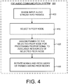
- FIG. 4 is a general flow diagram illustrating the general operation of the P2P audio communication system 300 shown in FIG. 3 .
- the P2P audio communication method divides an input audio stream into frames or packets and rotates the processing of the frames among the peer nodes in the P2P network. More specifically, the method begins by dividing an input audio stream into a plurality of frames (box 400). Next, one of the peer nodes in the P2P network is selected (box 410).
- the selected peer node is assigned to process frames proportional to the available resources of the selected node (box 420). In other words, a peer node having a large amount of resources is assigned a greater number of frames, while a peer node having a fewer amount of resources is assigned a fewer number of frames.
- Each peer node takes a turn processing the frames. Processing includes the mixing of audio content in the input audio stream and redelivery of the audio to the peer nodes. Thus, the selected peer node performs mixing of audio frames and redelivers the mixed audio frames to other peer nodes in the P2P network.
- the processing of the frames is rotated among the peer nodes (box 430). In a preferred embodiment, this rotation is performed in a round robin manner or fashion, such that each peer node takes a turn.
- FIG. 5 is a detailed block/flow diagram of the operation of the audio encoder 500 used in this working example.
- each frame was approximately 20 millisecond (ms) long. It should be noted that because there was a 50% overlap in between frames, the total algorithmic delay is 40 ms, which doubles that of the frame. Nevertheless, each quantized and entropy coded frame coefficients was still 20ms long.
- each frame was transformed by a modified discrete cosine transform (MDCT) module 520 into coefficient blocks ( C ij ) .
- MDCT discrete cosine transform
- the coefficient block C i,1 indicates the first frame for the l th peer and the coefficient block C i,2 indicates the second frame for the i th peer.
- the coefficient blocks were sent to a quantizer 530 and quantized.
- the quantized coefficient blocks then were entropy encoded by the entropy encoder 540 into packets p ij .
- the encoded packets P i,1 and P i,2 indicate encoded packets for the first and second frames of the i th peer.
- FIG. 6 is a detailed block/flow diagram of the operation of the audio mixer 600 used in this working example.
- the audio mixer 600 decodes the compressed audio packets of a certain frame to obtain coefficients blocks, combines the coefficient blocks, and re-encodes the blocks to obtain a single compressed audio packet for a frame of audio.
- the audio mixing technique of the P2P audio communication system and method mixes frames of the audio.
- the compressed audio packet P 1, j was decoded using an entropy decoder (1) 610 and an inverse quantizer (1) 620 to obtain a coefficient block for a certain peer.
- the compressed audio packet P 2, j was decoded using an entropy decoder (2) 630 and an inverse quantizer (2) 640 to obtain a coefficient block for a another peer.
- the resultant coefficients were MDCT transform coefficients. These MDCT transform coefficients then were added together or combined using the combination module 650, as shown by the "+" sign in the combination module 650. It should be noted that although a "+" sign is shown in FIG.
- combination may be subtraction (a minus sign "-") or addition (a plus sign "+”) and there will be no audible difference for the coded audio.
- the resultant coefficient block was quantized using a mixing quantizer 660 and then entropy re-encoded using a mixing entropy encoder 670. This generated a frame containing the mixed audio packet, P 1, j + P 2, j . No audio packets of any other frames were accessed during the mixing process.
- FIG. 7 is a detailed block/flow diagram of the operation of the audio decoder 700 used in this working example.
- the mixed packets were decoded normally.
- the mixed audio packet P 1, j + P 2, j was input to the audio decoder 700.
- Each frame was processed by the entropy decoder (3) 710 and then by the inverse quantizer (3) 720.
- the mixed MDCT transform coefficients were processed using the inverse MDCT module 730.
- the resultant output was the mixed audio waveform from peer 1 and 2 (audio 1 + audio 2) 740.
- Another component in this working example was the rotational mixing and redelivery of the audio content in a round robin manner.
- each of the peers take a turn in mixing and redelivering the audio content.
- a MutualCast clique was used that consisted of a small number of peer nodes that formed a fully connected mesh.
- the P2P audio conferencing system and method rotated the mixing and redelivery operation among the peers. This ensured that the bandwidth and computation load were appropriately distributed in the most efficient manner.
- the rotation was performed in a round robin manner or fashion such that each peer node took a turn mixing and redelivering the audio.
- FIG. 8 illustrates an audio mixing session for three peer nodes (1, 2 and 3) used in this working example.
- An audio mixing schedule is shown at the bottom of FIG. 8 .
- the peer nodes 1, 2 and 3 were in charge of audio mixing and redelivery at frames 3 k, 3 k +1 and 3 k +2, respectively.
- peer 2 mixed and redelivered the audio packets.
- peer 2 was in charge of mixing and redelivery
- peers 1 and 3 sent their coded audio P 1 , 1 and P 3,1 to peer 2, as shown in FIG. 8 .
- the incoming audio packets then were entropy decoded and inverse quantized back to the MDCT coefficients C 1,1 and C 3,1 .
- Peer 2 then added its own coefficients C 2,1 .
- the mixed audio then was sent back to peers 1 and 3.
- peer 2 added together coefficients C 1,1 and C 2,1 , quantized and entropy encoded the sum of the coefficients.
- Peer 2 then sent the mixed packet P 1,1 + P 2,1 back to peer 3.
- the mixed packet P 3,1 + P 2,1 was sent by peer 2 to peer 1.
- the mixed audio packets from the different peers were sorted, entropy decoded, inverse quantized and inverse MDCT transformed for play back.
- peer 3 assumed the mixing role. Peers 1 and 2 sent their compressed audio packets at the 2 nd frame P 1,2 and P 2,2 to peer 3. Peer 3 then mixed the incoming audio packets with its own coefficients C 3,2 . Next, peer 3 sent the mixed packet P 3,2 + P 2,2 to peer 1 and the mixed packet P 3,2 + P 1 ,2 to peer 2.
- peer node 1 became the mixing node, and so forth, as shown in FIG. 8 .
- the bandwidth and computational cost of the mixing is distributed among each of the peers.
- a group of less powerful peers can conduct a multi-party audio communication session without need for a server.
- a MutualCast clique consists of n nodes.
- Each peer node sends and receives 2( n -1) packets every n frames.
- ( n -1) packets are sent and received during the n-1 frames that it does not perform the mixing operation.
- ( n -1) packets are sent and received during the frame that it performs the mixing and redelivery operation.
- the upload/download bandwidth required is thus (2-2/n) ⁇ bw . It may also be calculated that on average, (2-2/n) streams of audio are decoded and re-encoded by each peer.
- the peer performs ( n -1) entropy decoding and inverse quantization operations, and ( n -1) forward quantization and entropy encoding operations.
- the mixed audio packet does not contain the source (or selected) peer nodes' audio content.
- the rotational audio mixing technique includes not mixing and not sending back a certain peer's source audio.
- the mixed audio packet contains audio content from each of the peer nodes and it is up to each peer node to subtract out its own audio content from the mixed audio packet.
- each peer is responsible for subtracting its own audio from the mixed audio. For example, peer i would subtract p i,j from m j , which is a mixing operation with subtraction instead of addition.
- the advantage of this alternate embodiment is that the peer only needs to perform a single forward quantization and entropy encoding operation during the mixing. Moreover, if IP multicast is supported among all the peers, the mixing peer may also multicast the mixed packet to the rest of the peers.
- the disadvantage of the alternate embodiment is that since the mixed audio needs to be quantized and entropy coded, the component audio p i,j in the mixed packet m j is different from the audio p i,j hold by the peer i. Thus, residual echo may persist. This residual echo is more obvious with the increase of the number of the peers and/or the decrease in the coding bitrate of the mixed audio. Thus, due to this residual echo problem, the preferred embodiment is to not mix all of the audio packets.
- the P2P audio communication system and method allocates the mixing and redelivery tasks of the audio on a frame-by-frame basis. In this manner, the P2P audio communication system and method assigns more mixing tasks to peers having greater resources, and fewer mixing tasks to peers having fewer resources.
- the paramount resource considered by the P2P audio communication system and method is the upload bandwidths of the peers. In increasingly common networks, the total upload bandwidths of the P2P network are much smaller than the total download bandwidths. This is especially true for end-user nodes on the cable modem and ADSL networks, for which the balance is asymmetrically skewed towards larger download bandwidth. Even for the user nodes on the university/corporate networks, the download bandwidth can still be larger than the available upload bandwidth as the user caps the upload bandwidth. Therefore, it is advantageous to allocate more mixing and redelivery tasks to the peer with higher available upload bandwidth, and fewer tasks to the peer with lower upload bandwidth.
- a second resource considered by the P2P audio communication system and method is the peak upload bandwidth (or the physical link bandwidth) of the peer.
- a peer of the P2P audio communication system and method receives and sends out ( n -1) audio packets to ( n -1) peers.
- the traffic characteristics of a peer in the P2P audio communication system is bursty. It is helpful to assign more mixing and redelivery tasks to the peer with a faster physical link, or the peer that is connected to the router with a relatively large token bucket, so that the delay caused by sending packets to multiple peers can be reduced.
- the download bandwidths and the computation resources of the peers are not a bottleneck. Nevertheless, the P2P audio communication system and method may also take these into consideration in the allocation as well. It should be noted that if the slower or less powerful nodes are allowed to deliver fewer packets, they become leeches of the faster, more powerful peers. Whether to allow such leech behavior is a design choice between better audio communication performance verses fairness on contribution.
- a MutualCast clique of the P2P audio communication system must be formed by a set of fully connected peer nodes. As shown above, the delay increases as the clique grows large. Accordingly, the number of nodes in a MutualCast clique ideally should not be very large. A reasonable number is between 3 to 7. Nevertheless, the MutualCast clique can serve as a super gateway or super server, and thus function in a much larger network, while retaining all the functionality of the P2P audio communication system and method described herein.
- the P2P audio communication system can function as a super gateway node. This allows the MutualCast clique to serve as a "super" gateway node in a large multi-party communication session. In this situation, the rest of the nodes form a generic graph and use end system mixing.
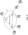
- FIG. 9 illustrates an exemplary example of a MutualCast clique of the P2P audio communication system and method serving as a gateway node in a generic multi-party communication session. This configuration is particularly well-suited for a multi-party communication session having a large number of peer nodes, where a small number of close-by nodes are fully connected and form a MutualCast clique.
- the MutualCast clique 900 formed by the nodes a, b and c serves as a "super" gateway node for nodes d, e, f, g and i .
- Each peer node in the MutualCast clique 900 serves as a gateway for the nodes attached.
- peer node a is attached to two nodes d and e outside of the MutualCast clique 900.
- node a merges the audio of d and e with its own, and delivers the combined audio ( a + d + e ) to nodes b and c using the P2P audio communication system and method.
- the combined audio ( a + d + e ) is mixed with the input from the node b (audio b + i ) and sent to node c.
- the combined audio ( a + d + e ) is mixed with the input from node c (audio c + f + g + h ) and sent to node b.
- the combined audio ( a + d + e ) is sent to the mixing node ( b or c ) at the moment.
- Node a also receives the mixed input from nodes b or c, combines them with its own to form the mixed frame m, and sends m + d to node e, and sends m + e to node d.
- the P2P audio communication system also can function as a super server.
- the remainder of the nodes are the client nodes in a star topology, and the MutualCast clique may consist as fewer as two nodes.
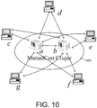
- FIG. 10 illustrates an exemplary example of a MutualCast clique as a super server in a multi-party communication session with a star topology.
- peer nodes a and b form a two-node MutualCast clique 1000, which serves as a super server for the rest client nodes c, d, e, f and g .
- the peer nodes in the MutualCast clique 1000 again form a fully connected mesh.
- each client node outside is connected to all peer nodes in the MutualCast clique 1000.
- This configuration is more suited for small-to-medium size networks (such as between 4 and 16), where there are a few powerful broadband nodes that share to serve as the server.
- the client nodes may be behind NAT/firewall. They can connect to the nodes that are directly connected to the Internet, in other words, those of the MutualCast clique 1000. However, they can not connect to each other.
- the mixing and redelivery operation of such network is very similar to the P2P audio communication system and method described above. The only difference is that in this embodiment the client nodes are exempted from the mixing and redelivery tasks.
- one peer of the MutualCast clique 1000 mixes and redelivers the audio packets for the rest of the peers, both inside and outside the MutualCast clique 1000.
- the bandwidth requirement of different audio communication session scenarios using the P2P audio communication system and method is calculated and compared to those scenarios not using the P2P audio communication system and method.
- the P2P audio communication system and method requires the upload/download bandwidth of (2 - 2/ n ) ⁇ bw for each and every peer node.
- the bandwidth required is 1.34 bw .
- the same three-node communication session needs a node with bandwidth at least 2 bw to conduct a multi-party communication session with either star topology, or generic graph.
- the P2P audio communication system and method can conduct multi-party communication sessions even when all peer nodes are less resourceful.
- the MutualCast clique serves as a super gateway in a large graph.
- the gateway node be connected to m nodes. Normally, the gateway node needs m ⁇ bw upload and download bandwidth to mix and redeliver the audio traffic.
- the upload/download bandwidth requirement of each node is reduced in this super gateway to: 2 + m ⁇ 2 n bw .
- the P2P audio communication system and method reduces the bandwidth requirement from 6 bw to 3.34 bw .
- the use of the MutualCast clique as a super gateway also may reduce the bandwidth requirement of the gateway nodes.
- the P2P audio communication system and method are designed to operate in a computing environment and on a computing device.
- the computing environment in which the P2P audio communication system and method operates will now be discussed. The following discussion is intended to provide a brief, general description of a suitable computing environment in which the P2P audio communication system and method may be implemented.
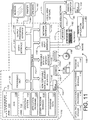
- FIG. 12 illustrates an example of a suitable computing system environment in which the P2P audio communication system and method shown in FIGS. 3 and 4 may be implemented.
- the computing system environment 1100 is only one example of a suitable computing environment and is not intended to suggest any limitation as to the scope of use or functionality of the invention. Neither should the computing environment 1100 be interpreted as having any dependency or requirement relating to any one or combination of components illustrated in the exemplary operating environment 1100.
- the P2P audio communication system and method is operational with numerous other general purpose or special purpose computing system environments or configurations.
- Examples of well known computing systems, environments, and/or configurations that may be suitable for use with the P2P audio communication system and method include, but are not limited to, personal computers, server computers, hand-held, laptop or mobile computer or communications devices such as cell phones and PDA's, multiprocessor systems, microprocessor-based systems, set top boxes, programmable consumer electronics, network PCs, minicomputers, mainframe computers, distributed computing environments that include any of the above systems or devices, and the like.
- the P2P audio communication system and method may be described in the general context of computer-executable instructions, such as program modules, being executed by a computer.
- program modules include routines, programs, objects, components, data structures, etc., that perform particular tasks or implement particular abstract data types.
- the P2P audio communication system and method may also be practiced in distributed computing environments where tasks are performed by remote processing devices that are linked through a communications network.
- program modules may be located in both local and remote computer storage media including memory storage devices.
- an exemplary system for implementing the P2P audio communication system and method includes a general-purpose computing device in the form of a computer 1110.
- the peer nodes shown in FIG. 11 are examples of the computer 1110.
- Components of the computer 1110 may include, but are not limited to, a processing unit 1120, a system memory 1130, and a system bus 1121 that couples various system components including the system memory to the processing unit 1120.
- the system bus 1121 may be any of several types of bus structures including a memory bus or memory controller, a peripheral bus, and a local bus using any of a variety of bus architectures.
- bus architectures include Industry Standard Architecture (ISA) bus, Micro Channel Architecture (MCA) bus, Enhanced ISA (EISA) bus, Video Electronics Standards Association (VESA) local bus, and Peripheral Component Interconnect (PCI) bus also known as Mezzanine bus.
- the computer 1110 typically includes a variety of computer readable media.
- Computer readable media can be any available media that can be accessed by the computer 1110 and includes both volatile and nonvolatile media, removable and non-removable media.
- Computer readable media may comprise computer storage media and communication media.
- Computer storage media includes volatile and nonvolatile removable and non-removable media implemented in any method or technology for storage of information such as computer readable instructions, data structures, program modules or other data.
- Computer storage media includes, but is not limited to, RAM, ROM, EEPROM, flash memory or other memory technology, CD-ROM, digital versatile disks (DVD) or other optical disk storage, magnetic cassettes, magnetic tape, magnetic disk storage or other magnetic storage devices, or any other medium which can be used to store the desired information and which can be accessed by the computer 1110.
- Communication media typically embodies computer readable instructions, data structures, program modules or other data in a modulated data signal such as a carrier wave or other transport mechanism and includes any information delivery media.
- modulated data signal means a signal that has one or more of its characteristics set or changed in such a manner as to encode information in the signal.
- communication media includes wired media such as a wired network or direct-wired connection, and wireless media such as acoustic, RF, infrared and other wireless media. Combinations of any of the above should also be included within the scope of computer readable media.
- the system memory 1130 includes computer storage media in the form of volatile and/or nonvolatile memory such as read only memory (ROM) 1131 and random access memory (RAM) 1132.
- ROM read only memory
- RAM random access memory
- BIOS basic input/output system
- RAM 1132 typically contains data and/or program modules that are immediately accessible to and/or presently being operated on by processing unit 1120.
- FIG. 11 illustrates operating system 1134, application programs 1135, other program modules 1136, and program data 1137.
- the computer 1110 may also include other removable/non-removable, volatile/nonvolatile computer storage media.
- FIG. 11 illustrates a hard disk drive 1141 that reads from or writes to non-removable, nonvolatile magnetic media, a magnetic disk drive 1151 that reads from or writes to a removable, nonvolatile magnetic disk 1152, and an optical disk drive 1155 that reads from or writes to a removable, nonvolatile optical disk 1156 such as a CD ROM or other optical media.
- removable/non-removable, volatile/nonvolatile computer storage media that can be used in the exemplary operating environment include, but are not limited to, magnetic tape cassettes, flash memory cards, digital versatile disks, digital video tape, solid state RAM, solid state ROM, and the like.
- the hard disk drive 1141 is typically connected to the system bus 1121 through a non-removable memory interface such as interface 1140, and magnetic disk drive 1151 and optical disk drive 1155 are typically connected to the system bus 1121 by a removable memory interface, such as interface 1150.
- the drives and their associated computer storage media discussed above and illustrated in FIG. 11 provide storage of computer readable instructions, data structures, program modules and other data for the computer 1110.
- hard disk drive 1141 is illustrated as storing operating system 1144, application programs 1145, other program modules 1146, and program data 1147. Note that these components can either be the same as or different from operating system 1134, application programs 1135, other program modules 1136, and program data 1137.
- Operating system 1144, application programs 1145, other program modules 1146, and program data 1147 are given different numbers here to illustrate that, at a minimum, they are different copies.
- a user may enter commands and information into the computer 1110 through input devices such as a keyboard 1162 and pointing device 1161, commonly referred to as a mouse, trackball or touch pad.
- Other input devices may include a microphone, joystick, game pad, satellite dish, scanner, radio receiver, or a television or broadcast video receiver, or the like. These and other input devices are often connected to the processing unit 1120 through a user input interface 1160 that is coupled to the system bus 1121, but may be connected by other interface and bus structures, such as, for example, a parallel port, game port or a universal serial bus (USB).
- a monitor 1191 or other type of display device is also connected to the system bus 1121 via an interface, such as a video interface 1190.
- computers may also include other peripheral output devices such as speakers 1197 and printer 1196, which may be connected through an output peripheral interface 1195.
- the computer 1110 may operate in a networked environment using logical connections to one or more remote computers, such as a remote computer 1180.
- the remote computer 1180 may be a personal computer, a server, a router, a network PC, a peer device or other common network node, and typically includes many or all of the elements described above relative to the computer 1110, although only a memory storage device 1181 has been illustrated in FIG. 11 .
- the logical connections depicted in FIG. 11 include a local area network (LAN) 1171 and a wide area network (WAN) 1173, but may also include other networks.
- LAN local area network
- WAN wide area network
- Such networking environments are commonplace in offices, enterprise-wide computer networks, intranets and the Internet.
- the computer 1110 When used in a LAN networking environment, the computer 1110 is connected to the LAN 1171 through a network interface or adapter 1170. When used in a WAN networking environment, the computer 1110 typically includes a modem 1172 or other means for establishing communications over the WAN 1173, such as the Internet.
- the modem 1172 which may be internal or external, may be connected to the system bus 1121 via the user input interface 1160, or other appropriate mechanism.
- program modules depicted relative to the computer 1110, or portions thereof may be stored in the remote memory storage device.
- FIG. 11 illustrates remote application programs 1185 as residing on memory device 1181. It will be appreciated that the network connections shown are exemplary and other means of establishing a communications link between the computers may be used.
Claims (9)
- Ein computerimplementierter Prozess zum Durchführen einer Echtzeitaudiokommunikationssitzung mit mehreren Parteien zwischen Peerknoten in einem Peer-to-Peer Computernetzwerk (200), wobei jeder der Peerknoten einen Audiostrom hat, wobei der Prozess umfasst:einen Paketteilungsschritt zum Teilen des Audiostroms von jedem der Peerknoten in Audiopakete,gekennzeichnet durcheinen Audiomischungsschritt zum Kombinieren von Audiopaketen von einer bestimmten Zeit von jedem der Peerknoten, um ein gemischtes Audiopaket zu dieser Zeit zu erzeugen undeinen Rotationsschritt zum Zuweisen von Audiomischung von gemischten Audiopaketen und Rücksendung der gemischten Audiopakete zu jedem der Peerknoten in einem Rotationsverfahren, so dass zumindest einige der Peerknoten dran sind, eine Audiomischung und eine Rücksendung durchzuführen.
- Der computerimplementierte Prozess nach Anspruch 1, weiter umfassend Rotieren der Audiomischung und Rücksendung zwischen zumindest einigen der Peerknoten in einem Reihumverfahren.
- Der computerimplementierte Prozess nach Anspruch 2, wobei der Audiomischungsschritt weiter umfasst:Kodieren der Audiopakete unter Verwendung eines Entropiekodierers, um entropiekodierte Audiopakete zu erzeugen undMischen der entropiekodierten Audiopakete auf einer Paket-für-Paket Basis.
- Der computerimplementierte Prozess nach Anspruch 3, weiter umfassend:Auswählen von entropiekodierten Audiopaketen zu der bestimmten Zeit von jedem der Peerknoten;Entropiedekodieren und inverses Quantisieren der ausgewählten Audiopakete, um Koeffizientenblöcke zu erzeugen, die jedem der ausgewählten Audiopakete entsprechen;Kombinieren der Koeffizientenblöcke, um einen resultierenden Koeffizientenblock für jeden der Peerknoten zu der bestimmten Zeit zu erzeugen undQuantisieren und erneutes Entropiekodieren des resultierenden Koeffizientenblocks, um das gemischte Audiopaket zu erzeugen.
- Der computerimplementierte Prozess nach Anspruch 1, weiter umfassend:Entropiedekodieren und inverses Quantisieren der gemischten Audiopakete in einem empfangenden Peerknoten, um gemischte Transformierungskoeffizienten zu erhalten undinverses modifiziertes diskretes Cosinustransformieren der gemischten Transformierungskoeffizienten, um Audioinhalt wieder herzustellen.
- Der computerimplementierte Prozess nach Anspruch 5, wobei der Audioinhalt weiter Audioinhalt von jedem der Peerknoten umfasst, außer von einem Quellpeerknoten, der Mischen und Rücksendung ausführt.
- Der computerimplementierte Prozess nach Anspruch 5, wobei der Audioinhalt Audioinhalt von jedem der Peerknoten umfasst und weiter umfasst, dass jeder der Peerknoten seinen eigenen Audioinhalt subtrahiert.
- Der computerimplementierte Prozess nach Anspruch 1, weiter umfassend:vollständiges Verbinden der Peerknoten, um eine Clique zu definieren; undOrganisieren einer Netzwerktopologie, so dass die Clique sich verhält wie eines von: (a) ein übergeordneter Gatewayknoten, der mit anderen Knoten außerhalb der Clique interagiert; (b) ein übergeordneter Server, so dass die Clique in einer Position eines Servers in einer Sternnetzwerktopologie ist, die mit Clientknoten außerhalb der Clique interagiert.
- Eine Peer-to-Peer Audiokommunikationsvorrichtung zum Einsetzen in einer Echtzeitaudiokommunikationssitzung mit mehreren Parteien zwischen Peerknoten in einem Peer-to-Peer Netzwerk (200), wobei die Vorrichtung umfasst:ein Audiopaketmodul, das ausgelegt ist, einen Eingangsaudiostrom, der Audioinhalt hat, in eine Vielzahl von Audiorahmen zu unterteilen,gekennzeichnet durcheinen Audiomischer (330, 600), der ausgelegt ist, ein Mischen der Audiorahmen von jedem der Peerknoten zu einem bestimmten Rahmen durchzuführen, um ein gemischtes Audiopaket zu jedem der Vielzahl von Audiorahmen zu erzeugen;eine Reihumausführungstechnik, die ausgelegt ist, Audiomischung und Rücksendung des gemischten Audioinhalts jeweils einzeln jedem der Peerknoten in einem Reihumverfahren zuzuweisen undein Audiodekodierer (700), der ausgelegt ist, den rückgesendeten gemischten Audioinhalt zu dekodieren, um Audio für die Audiokommunikationssitzung zu erhalten.
Applications Claiming Priority (1)
| Application Number | Priority Date | Filing Date | Title |
|---|---|---|---|
| US11/066,137 US7460495B2 (en) | 2005-02-23 | 2005-02-23 | Serverless peer-to-peer multi-party real-time audio communication system and method |
Publications (2)
| Publication Number | Publication Date |
|---|---|
| EP1696630A1 EP1696630A1 (de) | 2006-08-30 |
| EP1696630B1 true EP1696630B1 (de) | 2017-11-15 |
Family
ID=36046851
Family Applications (1)
| Application Number | Title | Priority Date | Filing Date |
|---|---|---|---|
| EP06100434.7A Active EP1696630B1 (de) | 2005-02-23 | 2006-01-17 | System und verfahren für peer-to-peer echtzeitaudiokommunikation zwischen mehreren parteien ohne server |
Country Status (3)
| Country | Link |
|---|---|
| US (1) | US7460495B2 (de) |
| EP (1) | EP1696630B1 (de) |
| JP (1) | JP4800792B2 (de) |
Families Citing this family (67)
| Publication number | Priority date | Publication date | Assignee | Title |
|---|---|---|---|---|
| JP4064964B2 (ja) * | 2002-07-04 | 2008-03-19 | ノキア コーポレイション | パケット交換型電話会議の管理方法、サーバ、及び端末装置 |
| US8095228B2 (en) * | 2004-05-27 | 2012-01-10 | Canon Kabushiki Kaisha | Data distribution apparatus, its control method, program, and storage medium |
| US9489717B2 (en) | 2005-01-31 | 2016-11-08 | Invention Science Fund I, Llc | Shared image device |
| US8902320B2 (en) | 2005-01-31 | 2014-12-02 | The Invention Science Fund I, Llc | Shared image device synchronization or designation |
| US20060170956A1 (en) | 2005-01-31 | 2006-08-03 | Jung Edward K | Shared image devices |
| US9124729B2 (en) | 2005-01-31 | 2015-09-01 | The Invention Science Fund I, Llc | Shared image device synchronization or designation |
| US9325781B2 (en) | 2005-01-31 | 2016-04-26 | Invention Science Fund I, Llc | Audio sharing |
| US9910341B2 (en) | 2005-01-31 | 2018-03-06 | The Invention Science Fund I, Llc | Shared image device designation |
| US9082456B2 (en) | 2005-01-31 | 2015-07-14 | The Invention Science Fund I Llc | Shared image device designation |
| US9942511B2 (en) | 2005-10-31 | 2018-04-10 | Invention Science Fund I, Llc | Preservation/degradation of video/audio aspects of a data stream |
| US9967424B2 (en) | 2005-06-02 | 2018-05-08 | Invention Science Fund I, Llc | Data storage usage protocol |
| US9001215B2 (en) | 2005-06-02 | 2015-04-07 | The Invention Science Fund I, Llc | Estimating shared image device operational capabilities or resources |
| US10003762B2 (en) | 2005-04-26 | 2018-06-19 | Invention Science Fund I, Llc | Shared image devices |
| US9621749B2 (en) | 2005-06-02 | 2017-04-11 | Invention Science Fund I, Llc | Capturing selected image objects |
| US9819490B2 (en) | 2005-05-04 | 2017-11-14 | Invention Science Fund I, Llc | Regional proximity for shared image device(s) |
| US9451200B2 (en) | 2005-06-02 | 2016-09-20 | Invention Science Fund I, Llc | Storage access technique for captured data |
| US8964054B2 (en) | 2006-08-18 | 2015-02-24 | The Invention Science Fund I, Llc | Capturing selected image objects |
| US20070222865A1 (en) | 2006-03-15 | 2007-09-27 | Searete Llc, A Limited Liability Corporation Of The State Of Delaware | Enhanced video/still image correlation |
| US9191611B2 (en) | 2005-06-02 | 2015-11-17 | Invention Science Fund I, Llc | Conditional alteration of a saved image |
| US20090144391A1 (en) * | 2007-11-30 | 2009-06-04 | Searete Llc, A Limited Liability Corporation Of The State Of Delaware | Audio sharing |
| US9076208B2 (en) | 2006-02-28 | 2015-07-07 | The Invention Science Fund I, Llc | Imagery processing |
| US7899170B2 (en) | 2005-04-28 | 2011-03-01 | Apple Inc. | Multi-participant conference setup |
| US7864209B2 (en) * | 2005-04-28 | 2011-01-04 | Apple Inc. | Audio processing in a multi-participant conference |
| US7817180B2 (en) * | 2005-04-28 | 2010-10-19 | Apple Inc. | Video processing in a multi-participant video conference |
| US8861701B2 (en) * | 2005-04-28 | 2014-10-14 | Apple Inc. | Multi-participant conference adjustments |
| US7949117B2 (en) * | 2005-04-28 | 2011-05-24 | Apple Inc. | Heterogeneous video conferencing |
| US7692682B2 (en) | 2005-04-28 | 2010-04-06 | Apple Inc. | Video encoding in a video conference |
| US7577110B2 (en) * | 2005-08-12 | 2009-08-18 | University Of Southern California | Audio chat system based on peer-to-peer architecture |
| JP5005210B2 (ja) * | 2005-11-11 | 2012-08-22 | 任天堂株式会社 | ネットワークゲームシステム、ネットワークゲームプログラムおよびネットワーク構築方法 |
| US8904456B2 (en) | 2006-02-13 | 2014-12-02 | Tvu Networks Corporation | Methods, apparatus, and systems for providing media content over a communications network |
| US7379450B2 (en) * | 2006-03-10 | 2008-05-27 | International Business Machines Corporation | System and method for peer-to-peer multi-party voice-over-IP services |
| CN101119252B (zh) * | 2006-08-01 | 2010-05-19 | 华为技术有限公司 | 接入网络系统、接入装置、arp代理方法和ip桥接转发方法 |
| US8837330B1 (en) * | 2006-10-10 | 2014-09-16 | Avaya Inc. | Methods, systems, and media for combining conferencing signals |
| DE602006004073D1 (de) * | 2006-11-23 | 2009-01-15 | Ntt Docomo Inc | |
| DE102006060043A1 (de) * | 2006-12-19 | 2008-06-26 | Siemens Ag | Verfahren und Sender zum Bereitstellen eines Datenstroms, Verfahren und Empfänger zum Abruf zumindest eines Datensegments eines Datenstroms |
| JP5012049B2 (ja) * | 2007-01-29 | 2012-08-29 | ヤマハ株式会社 | 通信システム及びサーバ |
| WO2008117295A2 (en) * | 2007-03-28 | 2008-10-02 | Unison Play Ltd. | Distributed storage management |
| KR100933938B1 (ko) * | 2007-08-22 | 2009-12-28 | 주식회사 버츄얼스톰 | 그리드컴퓨팅을 이용한 스트리밍 방법 및 이를 기록한기록매체 |
| US8397168B2 (en) | 2008-04-05 | 2013-03-12 | Social Communications Company | Interfacing with a spatial virtual communication environment |
| US7844724B2 (en) * | 2007-10-24 | 2010-11-30 | Social Communications Company | Automated real-time data stream switching in a shared virtual area communication environment |
| TWI492592B (zh) * | 2007-10-24 | 2015-07-11 | 社交通訊公司 | 在共享虛擬區通訊環境中之自動化即時資料串流交換技術 |
| US7769806B2 (en) * | 2007-10-24 | 2010-08-03 | Social Communications Company | Automated real-time data stream switching in a shared virtual area communication environment |
| US7636789B2 (en) * | 2007-11-27 | 2009-12-22 | Microsoft Corporation | Rate-controllable peer-to-peer data stream routing |
| TWI342715B (en) * | 2007-12-28 | 2011-05-21 | Ind Tech Res Inst | System and method for multi-participant conference without multipoint conferencing unit |
| KR20110009077A (ko) * | 2008-01-10 | 2011-01-27 | 휴렛-팩커드 디벨롭먼트 컴퍼니, 엘.피. | 멀티웨이 피어 투 피어 매체 스트리밍을 위한 방법, 멀티웨이 매체 스트리밍을 위한 방법 및 컴퓨터 판독 가능한 매체 |
| JP5058135B2 (ja) * | 2008-02-08 | 2012-10-24 | パナソニック株式会社 | 端末装置 |
| US20090248793A1 (en) * | 2008-03-25 | 2009-10-01 | Contribio Ab | Providing Content In a Network |
| US8126995B2 (en) * | 2008-06-23 | 2012-02-28 | Adobe Systems Incorporated | Multi-source broadcasting in peer-to-peer network |
| US7738406B2 (en) * | 2008-10-08 | 2010-06-15 | Microsoft Corporation | Models for routing tree selection in peer-to-peer communications |
| US9197678B2 (en) * | 2008-12-11 | 2015-11-24 | Skype | Method and system for data transmission |
| US9853922B2 (en) | 2012-02-24 | 2017-12-26 | Sococo, Inc. | Virtual area communications |
| US9141275B2 (en) * | 2009-02-17 | 2015-09-22 | Hewlett-Packard Development Company, L.P. | Rendering object icons associated with a first object icon upon detecting fingers moving apart |
| CN102077508B (zh) * | 2009-03-18 | 2013-06-19 | 松下电器产业株式会社 | 在多节点间通过网络对数据进行接收和转发的组播通信方法及装置 |
| US8155048B2 (en) * | 2009-03-27 | 2012-04-10 | Mitsubishi Electric Research Laboratories, Inc. | Resource allocation for rateless transmissions |
| JP5785082B2 (ja) * | 2009-08-20 | 2015-09-24 | ジーブイビービー ホールディングス エス.エイ.アール.エル. | オーディオ・ストリームを合成する装置、方法及びプログラム |
| US8483101B2 (en) * | 2009-09-16 | 2013-07-09 | Mitel Networks Corporation | System and method for cascaded teleconferencing |
| US8565139B2 (en) * | 2009-10-29 | 2013-10-22 | Symbol Technologies, Inc. | Methods and apparatus for WAN/WLAN unicast and multicast communication |
| EP2544424A4 (de) | 2010-03-04 | 2015-05-06 | Telefónica S A | Mehrpunkt-konferenzverfahren ohne verwendung eines servers |
| US8433755B2 (en) | 2010-04-07 | 2013-04-30 | Apple Inc. | Dynamic designation of a central distributor in a multi-participant conference |
| US8711736B2 (en) | 2010-09-16 | 2014-04-29 | Apple Inc. | Audio processing in a multi-participant conference |
| US8677006B2 (en) * | 2011-05-05 | 2014-03-18 | Microsoft Corporation | Processing media streams |
| JP6295675B2 (ja) * | 2014-01-20 | 2018-03-20 | ヤマハ株式会社 | 音楽セッションシステム、方法及び端末装置 |
| US9510083B2 (en) | 2014-03-14 | 2016-11-29 | Apple Inc. | Managing connections of a user device |
| EP3130130A4 (de) * | 2014-04-11 | 2017-07-26 | Diro, Inc. | Dynamische kontextuelle vorrichtungsnetzwerke |
| US9693137B1 (en) | 2014-11-17 | 2017-06-27 | Audiohand Inc. | Method for creating a customizable synchronized audio recording using audio signals from mobile recording devices |
| EP4074025A4 (de) * | 2019-12-09 | 2023-11-22 | Vowel, Inc. | Nutzung eines netzwerks von mikrofonen zur schlussfolgerung des raumortes und der sprecheridentität für genauere transkriptionen und semantischen kontext bei besprechungen |
| CN113257256A (zh) * | 2021-07-14 | 2021-08-13 | 广州朗国电子科技股份有限公司 | 一种语音处理方法、会议一体机、系统及存储介质 |
Family Cites Families (13)
| Publication number | Priority date | Publication date | Assignee | Title |
|---|---|---|---|---|
| CN100393092C (zh) * | 1998-11-16 | 2008-06-04 | 西门子公司 | 使多点连接成为可能的电话多媒体终端机 |
| DE60130665T2 (de) * | 2000-08-25 | 2008-06-26 | British Telecommunications P.L.C. | Audiodatenverarbeitung |
| US7069208B2 (en) * | 2001-01-24 | 2006-06-27 | Nokia, Corp. | System and method for concealment of data loss in digital audio transmission |
| US7266091B2 (en) * | 2001-02-28 | 2007-09-04 | The Trustees Of Columbia University In City Of New York | System and method for conferencing in inter/intranet telephony |
| US6763025B2 (en) * | 2001-03-12 | 2004-07-13 | Advent Networks, Inc. | Time division multiplexing over broadband modulation method and apparatus |
| US7016315B2 (en) | 2001-03-26 | 2006-03-21 | Motorola, Inc. | Token passing arrangement for a conference call bridge arrangement |
| US20020178260A1 (en) * | 2001-05-23 | 2002-11-28 | Chang Hsin-Wang Wayne | Distributed computer resource bartering system |
| JP2003124953A (ja) * | 2001-10-15 | 2003-04-25 | Fujitsu Ltd | リング型ネットワークシステム |
| US7027982B2 (en) * | 2001-12-14 | 2006-04-11 | Microsoft Corporation | Quality and rate control strategy for digital audio |
| JP3864839B2 (ja) * | 2002-04-26 | 2007-01-10 | ヤマハ株式会社 | 通信ネットワークを利用した音楽セッションシステム及びこの音楽セッションシステムに用いられるユーザ端末装置 |
| US7657779B2 (en) * | 2002-09-18 | 2010-02-02 | International Business Machines Corporation | Client assisted autonomic computing |
| US7426219B2 (en) | 2003-02-26 | 2008-09-16 | Avaya Inc. | Method and apparatus for reducing packet data mixer delay |
| US7353255B2 (en) * | 2003-10-30 | 2008-04-01 | International Business Machines Corporation | System and apparatus for geographically distributed VoIP conference service with enhanced QoS |
-
2005
- 2005-02-23 US US11/066,137 patent/US7460495B2/en active Active
-
2006
- 2006-01-17 EP EP06100434.7A patent/EP1696630B1/de active Active
- 2006-02-23 JP JP2006047524A patent/JP4800792B2/ja not_active Expired - Fee Related
Non-Patent Citations (1)
| Title |
|---|
| None * |
Also Published As
| Publication number | Publication date |
|---|---|
| US20060187860A1 (en) | 2006-08-24 |
| JP4800792B2 (ja) | 2011-10-26 |
| US7460495B2 (en) | 2008-12-02 |
| EP1696630A1 (de) | 2006-08-30 |
| JP2006268844A (ja) | 2006-10-05 |
Similar Documents
| Publication | Publication Date | Title |
|---|---|---|
| EP1696630B1 (de) | System und verfahren für peer-to-peer echtzeitaudiokommunikation zwischen mehreren parteien ohne server | |
| EP2485431B1 (de) | Verfahren und Endgerät in einem Mehrpunkt-zu-mehrpunkt-Interkomsystem | |
| US6839734B1 (en) | Multimedia communications software with network streaming and multi-format conferencing | |
| US7313593B1 (en) | Method and apparatus for providing full duplex and multipoint IP audio streaming | |
| US9532002B2 (en) | System for enabling meshed conferences to be seamlessly promoted to full MCU based conferences | |
| Singh et al. | Centralized conferencing using SIP | |
| EP1633112A1 (de) | Vorrichtung und Verfahren zur Radierungskodierung von einem Medienstrom | |
| Blum et al. | WebRTC-Realtime Communication for the Open Web Platform: What was once a way to bring audio and video to the web has expanded into more use cases we could ever imagine. | |
| Rudkin et al. | Real-time applications on the Internet | |
| Li | Mutualcast: A serverless peer-to-peer multiparty real-time audio conferencing system | |
| Radenkovic et al. | Multi-party distributed audio service with TCP fairness | |
| Zimmermann et al. | Audiopeer: A collaborative distributed audio chat system | |
| Aguirre et al. | Darkcube: A k-Hypercube based P2P VoIP protocol | |
| Layaida et al. | A framework for dynamically configurable and reconfigurable network-based multimedia adaptations. | |
| Uyar et al. | An integrated videoconferencing system for heterogeneous multimedia collaboration | |
| Dyck | A survey of application-layer networking techniques for real-time distributed groupware | |
| Wang et al. | CoMAC: A cooperation-based multiparty audio conferencing system for mobile users | |
| Prasad et al. | Deployment issues of a VoIP conferencing system in a virtual conferencing environment | |
| Walter et al. | WebRTC multipoint conferencing with recording using a Media Server | |
| Nuño et al. | Using self-regulation to increase resilience in overlay networks for interactive multimedia communications | |
| Radenkovic et al. | A scaleable and adaptive audio service to support large scale collaborative work and entertainment | |
| Huang et al. | An adaptive mixing audio gateway in heterogeneous networks for ADMIRE system | |
| Chodorek | An analysis of architecture of videoconferencing system based on concept of active network | |
| Radenkovic et al. | A scaleable audio service to support many simultaneous speakers | |
| De Silva et al. | Optimized Video Conferencing System using Web Real Time Communication |
Legal Events
| Date | Code | Title | Description |
|---|---|---|---|
| PUAI | Public reference made under article 153(3) epc to a published international application that has entered the european phase |
Free format text: ORIGINAL CODE: 0009012 |
|
| AK | Designated contracting states |
Kind code of ref document: A1 Designated state(s): AT BE BG CH CY CZ DE DK EE ES FI FR GB GR HU IE IS IT LI LT LU LV MC NL PL PT RO SE SI SK TR |
|
| AX | Request for extension of the european patent |
Extension state: AL BA HR MK YU |
|
| 17P | Request for examination filed |
Effective date: 20070209 |
|
| 17Q | First examination report despatched |
Effective date: 20070328 |
|
| AKX | Designation fees paid |
Designated state(s): AT BE BG CH CY CZ DE DK EE ES FI FR GB GR HU IE IS IT LI LT LU LV MC NL PL PT RO SE SI SK TR |
|
| RAP1 | Party data changed (applicant data changed or rights of an application transferred) |
Owner name: MICROSOFT TECHNOLOGY LICENSING, LLC |
|
| GRAP | Despatch of communication of intention to grant a patent |
Free format text: ORIGINAL CODE: EPIDOSNIGR1 |
|
| INTG | Intention to grant announced |
Effective date: 20170622 |
|
| GRAS | Grant fee paid |
Free format text: ORIGINAL CODE: EPIDOSNIGR3 |
|
| GRAA | (expected) grant |
Free format text: ORIGINAL CODE: 0009210 |
|
| AK | Designated contracting states |
Kind code of ref document: B1 Designated state(s): AT BE BG CH CY CZ DE DK EE ES FI FR GB GR HU IE IS IT LI LT LU LV MC NL PL PT RO SE SI SK TR |
|
| REG | Reference to a national code |
Ref country code: CH Ref legal event code: EP Ref country code: GB Ref legal event code: FG4D Ref country code: AT Ref legal event code: REF Ref document number: 947305 Country of ref document: AT Kind code of ref document: T Effective date: 20171115 |
|
| REG | Reference to a national code |
Ref country code: FR Ref legal event code: PLFP Year of fee payment: 13 |
|
| REG | Reference to a national code |
Ref country code: IE Ref legal event code: FG4D |
|
| REG | Reference to a national code |
Ref country code: DE Ref legal event code: R096 Ref document number: 602006054089 Country of ref document: DE |
|
| REG | Reference to a national code |
Ref country code: NL Ref legal event code: FP |
|
| REG | Reference to a national code |
Ref country code: LT Ref legal event code: MG4D |
|
| REG | Reference to a national code |
Ref country code: AT Ref legal event code: MK05 Ref document number: 947305 Country of ref document: AT Kind code of ref document: T Effective date: 20171115 |
|
| PG25 | Lapsed in a contracting state [announced via postgrant information from national office to epo] |
Ref country code: FI Free format text: LAPSE BECAUSE OF FAILURE TO SUBMIT A TRANSLATION OF THE DESCRIPTION OR TO PAY THE FEE WITHIN THE PRESCRIBED TIME-LIMIT Effective date: 20171115 Ref country code: ES Free format text: LAPSE BECAUSE OF FAILURE TO SUBMIT A TRANSLATION OF THE DESCRIPTION OR TO PAY THE FEE WITHIN THE PRESCRIBED TIME-LIMIT Effective date: 20171115 Ref country code: SE Free format text: LAPSE BECAUSE OF FAILURE TO SUBMIT A TRANSLATION OF THE DESCRIPTION OR TO PAY THE FEE WITHIN THE PRESCRIBED TIME-LIMIT Effective date: 20171115 Ref country code: LT Free format text: LAPSE BECAUSE OF FAILURE TO SUBMIT A TRANSLATION OF THE DESCRIPTION OR TO PAY THE FEE WITHIN THE PRESCRIBED TIME-LIMIT Effective date: 20171115 |
|
| PG25 | Lapsed in a contracting state [announced via postgrant information from national office to epo] |
Ref country code: BG Free format text: LAPSE BECAUSE OF FAILURE TO SUBMIT A TRANSLATION OF THE DESCRIPTION OR TO PAY THE FEE WITHIN THE PRESCRIBED TIME-LIMIT Effective date: 20180215 Ref country code: LV Free format text: LAPSE BECAUSE OF FAILURE TO SUBMIT A TRANSLATION OF THE DESCRIPTION OR TO PAY THE FEE WITHIN THE PRESCRIBED TIME-LIMIT Effective date: 20171115 Ref country code: GR Free format text: LAPSE BECAUSE OF FAILURE TO SUBMIT A TRANSLATION OF THE DESCRIPTION OR TO PAY THE FEE WITHIN THE PRESCRIBED TIME-LIMIT Effective date: 20180216 Ref country code: AT Free format text: LAPSE BECAUSE OF FAILURE TO SUBMIT A TRANSLATION OF THE DESCRIPTION OR TO PAY THE FEE WITHIN THE PRESCRIBED TIME-LIMIT Effective date: 20171115 |
|
| PG25 | Lapsed in a contracting state [announced via postgrant information from national office to epo] |
Ref country code: CY Free format text: LAPSE BECAUSE OF FAILURE TO SUBMIT A TRANSLATION OF THE DESCRIPTION OR TO PAY THE FEE WITHIN THE PRESCRIBED TIME-LIMIT Effective date: 20171115 Ref country code: EE Free format text: LAPSE BECAUSE OF FAILURE TO SUBMIT A TRANSLATION OF THE DESCRIPTION OR TO PAY THE FEE WITHIN THE PRESCRIBED TIME-LIMIT Effective date: 20171115 Ref country code: DK Free format text: LAPSE BECAUSE OF FAILURE TO SUBMIT A TRANSLATION OF THE DESCRIPTION OR TO PAY THE FEE WITHIN THE PRESCRIBED TIME-LIMIT Effective date: 20171115 Ref country code: SK Free format text: LAPSE BECAUSE OF FAILURE TO SUBMIT A TRANSLATION OF THE DESCRIPTION OR TO PAY THE FEE WITHIN THE PRESCRIBED TIME-LIMIT Effective date: 20171115 Ref country code: CZ Free format text: LAPSE BECAUSE OF FAILURE TO SUBMIT A TRANSLATION OF THE DESCRIPTION OR TO PAY THE FEE WITHIN THE PRESCRIBED TIME-LIMIT Effective date: 20171115 |
|
| REG | Reference to a national code |
Ref country code: DE Ref legal event code: R097 Ref document number: 602006054089 Country of ref document: DE |
|
| PG25 | Lapsed in a contracting state [announced via postgrant information from national office to epo] |
Ref country code: PL Free format text: LAPSE BECAUSE OF FAILURE TO SUBMIT A TRANSLATION OF THE DESCRIPTION OR TO PAY THE FEE WITHIN THE PRESCRIBED TIME-LIMIT Effective date: 20171115 Ref country code: IT Free format text: LAPSE BECAUSE OF FAILURE TO SUBMIT A TRANSLATION OF THE DESCRIPTION OR TO PAY THE FEE WITHIN THE PRESCRIBED TIME-LIMIT Effective date: 20171115 Ref country code: RO Free format text: LAPSE BECAUSE OF FAILURE TO SUBMIT A TRANSLATION OF THE DESCRIPTION OR TO PAY THE FEE WITHIN THE PRESCRIBED TIME-LIMIT Effective date: 20171115 |
|
| REG | Reference to a national code |
Ref country code: CH Ref legal event code: PL |
|
| PLBE | No opposition filed within time limit |
Free format text: ORIGINAL CODE: 0009261 |
|
| STAA | Information on the status of an ep patent application or granted ep patent |
Free format text: STATUS: NO OPPOSITION FILED WITHIN TIME LIMIT |
|
| 26N | No opposition filed |
Effective date: 20180817 |
|
| PG25 | Lapsed in a contracting state [announced via postgrant information from national office to epo] |
Ref country code: LU Free format text: LAPSE BECAUSE OF NON-PAYMENT OF DUE FEES Effective date: 20180117 |
|
| REG | Reference to a national code |
Ref country code: IE Ref legal event code: MM4A |
|
| REG | Reference to a national code |
Ref country code: BE Ref legal event code: MM Effective date: 20180131 |
|
| PG25 | Lapsed in a contracting state [announced via postgrant information from national office to epo] |
Ref country code: SI Free format text: LAPSE BECAUSE OF FAILURE TO SUBMIT A TRANSLATION OF THE DESCRIPTION OR TO PAY THE FEE WITHIN THE PRESCRIBED TIME-LIMIT Effective date: 20171115 Ref country code: BE Free format text: LAPSE BECAUSE OF NON-PAYMENT OF DUE FEES Effective date: 20180131 Ref country code: LI Free format text: LAPSE BECAUSE OF NON-PAYMENT OF DUE FEES Effective date: 20180131 Ref country code: CH Free format text: LAPSE BECAUSE OF NON-PAYMENT OF DUE FEES Effective date: 20180131 |
|
| PG25 | Lapsed in a contracting state [announced via postgrant information from national office to epo] |
Ref country code: IE Free format text: LAPSE BECAUSE OF NON-PAYMENT OF DUE FEES Effective date: 20180117 |
|
| PG25 | Lapsed in a contracting state [announced via postgrant information from national office to epo] |
Ref country code: MC Free format text: LAPSE BECAUSE OF FAILURE TO SUBMIT A TRANSLATION OF THE DESCRIPTION OR TO PAY THE FEE WITHIN THE PRESCRIBED TIME-LIMIT Effective date: 20171115 |
|
| PG25 | Lapsed in a contracting state [announced via postgrant information from national office to epo] |
Ref country code: TR Free format text: LAPSE BECAUSE OF FAILURE TO SUBMIT A TRANSLATION OF THE DESCRIPTION OR TO PAY THE FEE WITHIN THE PRESCRIBED TIME-LIMIT Effective date: 20171115 |
|
| PG25 | Lapsed in a contracting state [announced via postgrant information from national office to epo] |
Ref country code: HU Free format text: LAPSE BECAUSE OF FAILURE TO SUBMIT A TRANSLATION OF THE DESCRIPTION OR TO PAY THE FEE WITHIN THE PRESCRIBED TIME-LIMIT; INVALID AB INITIO Effective date: 20060117 Ref country code: PT Free format text: LAPSE BECAUSE OF FAILURE TO SUBMIT A TRANSLATION OF THE DESCRIPTION OR TO PAY THE FEE WITHIN THE PRESCRIBED TIME-LIMIT Effective date: 20171115 |
|
| PG25 | Lapsed in a contracting state [announced via postgrant information from national office to epo] |
Ref country code: IS Free format text: LAPSE BECAUSE OF FAILURE TO SUBMIT A TRANSLATION OF THE DESCRIPTION OR TO PAY THE FEE WITHIN THE PRESCRIBED TIME-LIMIT Effective date: 20180315 |
|
| REG | Reference to a national code |
Ref country code: DE Ref legal event code: R079 Ref document number: 602006054089 Country of ref document: DE Free format text: PREVIOUS MAIN CLASS: H04L0029060000 Ipc: H04L0065000000 |
|
| PGFP | Annual fee paid to national office [announced via postgrant information from national office to epo] |
Ref country code: NL Payment date: 20211216 Year of fee payment: 17 |
|
| PGFP | Annual fee paid to national office [announced via postgrant information from national office to epo] |
Ref country code: DE Payment date: 20211130 Year of fee payment: 17 |
|
| PGFP | Annual fee paid to national office [announced via postgrant information from national office to epo] |
Ref country code: GB Payment date: 20221201 Year of fee payment: 18 Ref country code: FR Payment date: 20221208 Year of fee payment: 18 |
|
| P01 | Opt-out of the competence of the unified patent court (upc) registered |
Effective date: 20230505 |
|
| REG | Reference to a national code |
Ref country code: DE Ref legal event code: R119 Ref document number: 602006054089 Country of ref document: DE |
|
| REG | Reference to a national code |
Ref country code: NL Ref legal event code: MM Effective date: 20230201 |
|
| PG25 | Lapsed in a contracting state [announced via postgrant information from national office to epo] |
Ref country code: NL Free format text: LAPSE BECAUSE OF NON-PAYMENT OF DUE FEES Effective date: 20230201 Ref country code: DE Free format text: LAPSE BECAUSE OF NON-PAYMENT OF DUE FEES Effective date: 20230801 |