EP1696181A1 - Radiator with an external electric heating element - Google Patents
Radiator with an external electric heating element Download PDFInfo
- Publication number
- EP1696181A1 EP1696181A1 EP06001233A EP06001233A EP1696181A1 EP 1696181 A1 EP1696181 A1 EP 1696181A1 EP 06001233 A EP06001233 A EP 06001233A EP 06001233 A EP06001233 A EP 06001233A EP 1696181 A1 EP1696181 A1 EP 1696181A1
- Authority
- EP
- European Patent Office
- Prior art keywords
- heating element
- electrical
- radiator
- insulation means
- heating
- Prior art date
- Legal status (The legal status is an assumption and is not a legal conclusion. Google has not performed a legal analysis and makes no representation as to the accuracy of the status listed.)
- Withdrawn
Links
Images

Classifications
-
- F—MECHANICAL ENGINEERING; LIGHTING; HEATING; WEAPONS; BLASTING
- F24—HEATING; RANGES; VENTILATING
- F24H—FLUID HEATERS, e.g. WATER OR AIR HEATERS, HAVING HEAT-GENERATING MEANS, e.g. HEAT PUMPS, IN GENERAL
- F24H3/00—Air heaters
- F24H3/002—Air heaters using electric energy supply
- F24H3/004—Air heaters using electric energy supply with a closed circuit for a heat transfer liquid
Definitions
- the present invention relates to a radiator which is at least partially filled with a heating medium or can be flowed through by a heating medium, wherein at least one is provided on an outer side of the radiator with the interposition of a first electrically insulating insulating means mounted electrical heating element.
- radiators are known for example from German Utility Model DE 299 18 763 U1.
- the electric heating element is used as additional heating for the radiator, which allows in particular in the transitional period of spring or autumn electrical heating when the central heating system is already or still off.
- Object of the present invention is therefore to provide a structurally simple and inexpensive to manufacture radiator of the type mentioned above, which is characterized by a particularly high level of safety and represents no danger to users even with damage to the insulation.
- the radiator should be safe to operate in damp rooms, especially in the immediate vicinity of a shower or a bath.
- At least two electrically insulating insulating means are arranged on the radiator and / or on the at least one electric heating element, that both the first and the second insulating means between the radiator and the at least one electric heating element are effective ,
- the main advantage lies in the fact that a double insulation of the electric heating element is given to the radiator. Therefore, even with the damage of an insulating agent still a fully effective second insulation means is present, so that a risk of persons with very high security can be excluded.
- the electrical heating element is completely surrounded by at least one insulating means or completely by both insulation means.
- the safety compared to the prior art embodiment according to DE 299 18 763 U1 can be further increased, since there touching the exposed outside of the electric heating element is possible.
- a particularly small-sized and thus visually less disturbing embodiment can be achieved in that one or both insulating means is or are formed by a coating of the electric heating element. This allows a particularly flat design.
- the insulating means may also be in the form of layers, for example by a plastic layer and / or by an enamel layer.
- first insulating means and / or the second insulating means comprises an enamel coating, a particularly good efficiency of the electrical insulation means can be achieved.
- first insulating means and / or the second insulating means may consist of a plastic, preferably of a thermoplastic material.
- both insulation means may consist of different materials or of different material compositions. According to an alternative embodiment of the invention, however, both insulation means may consist of the same material or of the same material composition.
- two insulation means abut each other directly.
- two insulation layers can be applied one above the other.
- the second insulation means may be arranged at a distance from the first insulation means. This distance can be left free or completely or partially filled with intermediate elements.
- an intermediate element in particular an intermediate layer, is arranged between the two insulation means.
- an intermediate layer or at least one intermediate element can be arranged at one point or at several points between the two insulation means.
- the intermediate element or the intermediate layer comprises at least one electrical conductor.
- one or more electrical interconnects may be provided as an intermediate element or an electrically conductive layer, in particular a film, as an intermediate layer.
- both electrical insulation layers can be made particularly thin, since their required effect is individually detectable, so that unnecessarily large layer thicknesses, which would be necessary for the sake of safety, without the possibility of separate measurement of the two insulating layers for sufficient effectiveness, can be avoided.
- the required for the approval of a radiator with additional electric heater insulation effect for example, already be demonstrated at a thickness of the insulating layers, which is reduced over the standard required layer thicknesses by up to 80 to 90%.
- Thinner insulation layers in turn, not only save space, but above all an advantage in the efficiency of the desired electric heating element, which allows a more cost-effective operation of the electric heater.
- the intermediate element comprises at least one electrical conductor track, which is applied to the first electrical insulation means, and in that the second electrical insulation means is applied to the at least one electrical conductor track in such a way that it is not covered by the electrical conductor track Areas of the first electrical insulation means comes into contact.
- the electrical conductor track applied to the first electrical insulation means can be cast into the insulation layer forming the second electrical insulation means.
- At least on the side facing away from the radiator side of the electric heating element is provided at least one mechanical insulation means which prevents direct contact of persons or objects with the electric heating element.
- the mechanical insulation means can be formed for example by a plurality of bridge elements.
- these bridge elements may be arranged in the form of a cage, so that a free air circulation is not hindered on the electric heating element.
- the mechanical insulation means is designed in the form of a housing which is formed completely or at least predominantly closed.
- the housing may be made entirely or partially of plastic or preferably of metal, in particular of aluminum.
- the heating element is designed as a PTC heating element.
- a positive temperature coefficient (PTC) heating element has self-regulating semiconductor elements and therefore can be operated without a thermostat.
- the electrical heating element comprises a carrier element, on which at least one electrical heating resistor is preferably applied directly or indirectly in tracks extending in a U-shaped manner.
- the support member may be formed in particular by a flat sheet.
- the support member may also be designed bendable or bent in order to adapt to different radiator surfaces can.
- the radiator according to the invention may preferably be provided for connection to a central heating system, wherein it has a flow connection for the supply of a heating medium and a return connection for the discharge of the heating medium.
- the present invention also relates to an electric heater with at least one electric heating element that can be attached to a radiator of the type described above. It comprises at least two electrically insulating insulating means which can be effective between the at least one electric heating element and a radiator. Furthermore, at least one intermediate element or an intermediate layer, which comprises at least one electrical conductor, is arranged between the two electrically insulating insulation means at least at one location.
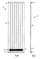
- FIG. 1 shows a panel heater 1 comprising a front heating plate 2 and a rear heating plate 3. Both heating plates 2, 3 are flowed through by the heating medium of a central heating system.
- the rear heating plate 3 has on its back four holding devices 4, via which the radiator 1 can be mounted on a wall.
- an electric heating element 6 is attached in the lower edge region 5 of the rear heating plate 3.
- This attachment can for example be made cohesively, in particular by gluing or non-positively via clamping means.
- the electric heating element 6 is thus applied to the outside of the radiator 1 and is not in contact with the heating medium.
- a tubular heater 1 is shown, the bottom and top each having a horizontally extending manifold 7 and a plurality of extending therebetween, here flat-shaped heating tubes 8. Both the two distribution pipes 7 and the heating pipes 8 are flowed through during operation by the heating medium of a central heating system. Slightly above the lower manifold 7, an electric heating element 6 is mounted on the back of the heating tubes 8, which may also be fixed cohesively or non-positively. Again, the electric heating element 6 is externally applied to the radiator 1 and is not in contact with the heating medium.
- the heating element 6 is designed as a flat component is very thin and thus takes up very little space. Since it is mounted on the back of the radiator 1, it can not be seen from the room facing the front. There are also no disturbing and outwardly projecting sockets available, as they are required in conventional heating cartridges that come into contact with the heating medium inside a radiator.
- At least two electrically insulating insulating means 9 and 10 are arranged between the heating element 1 and the electric heating element 6, which in this way isolate the heating element 1 twice from the electric heating element 6 and enable particularly safe operation.
- Both insulation means 9, 10 are here layered designed as enamel coating.
- the electric heating element 6 is applied to a flat support plate 11, the electrical resistance paths 12 carries directly or indirectly.
- the electrical resistance paths 12 are applied directly to the support plate 11, for example, printed.
- the two insulation layers 9 and 10 are located here between the radiator 1 and the support plate 11, wherein the electrical resistance paths 12 are located on the surface facing away from the radiator 1 surface of the support plate 11.
- they may also be covered there by a coating and / or by a mechanical insulation means, in particular by a plastic cage to further increase the security.
- the support plate 11 is fastened directly on the radiator 1.
- the two electrical insulation layers 9 and 10 are in this case between the support plate 11 and the electrical resistance paths 12, which are applied to the second insulation layer 10.
- further outer coating and / or an external mechanical insulation means for example a plastic cage, may be provided to further increase safety.
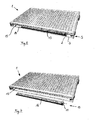
- FIGs 6 and 7 a plate heater 1 with a front heating plate 2 and a rear heating plate 3 is shown.
- an electric heater 13 is provided here, in the lower region 5 of the radiator 1 between the two heating plates 2 and 3 on a the inside surfaces 14 of the two heating plates 2, 3 can be attached. In this way, the electric heater 13 in the inner space 15 of the radiator 1 can be mounted. It can only be seen from the bottom of the radiator 1 ago, which is not possible with a conventional wall mounting of the radiator and thus visually not noticeable.
- the electric heater 13 can be attached cohesively, in particular by gluing, or non-positively via clamping means.
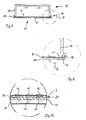
- the also subsequently attachable and in Figure 7 also detached from the radiator 1 shown as an independent unit electric heater 13 has a housing made of aluminum 16, which is shown in Figure 8 in cross section. It consists of a thermally conductive base plate formed by a support plate 11 and a housing upper part 17 attached thereto, which by means of a seal 18 which is inserted into a groove formed on the free edge 19 of the upper housing part 17, with respect to the support plate 11 and against the thereof applied insulating layers 9 and 10 is sealed (Figure 9). This results in a splash-proof embodiment, which allows in particular the use in bathrooms.
- the electric heating element 6 which also includes a plurality of electrical resistance paths 12 here.
- the resistance tracks 12 are applied to the first insulation layer 9, which in turn is applied to the second insulation layer 10, which is thus further away from the heating element 6 than the first insulation layer 9.
- the second insulation layer 10 is in turn applied to the support plate 11 (FIG ).
- drawing elements for parallel operation of a plurality of heating resistors 12 and / or a thermostat in particular a contact thermostat can be arranged.
- a plurality of electrical conductor tracks 20 are between the two insulation layers 9 and 10 arranged, which together form an intermediate element 21.
- the electrical conductor tracks 20 are first applied to the second insulation layer 10, which is further removed from the heating element 6, and then encapsulated by the first insulation layer 9.
- the electrical conductors 20 are completely surrounded not only on their top and bottom, but also on their side edges of the insulating layers 9, 10. In the areas not covered by the electrical conductor tracks 20, the two insulation layers 9 and 10 directly adjoin one another.
Abstract
Description
Die vorliegende Erfindung betrifft einen Heizkörper, der zumindest teilweise mit einem Heizmedium gefüllt oder von einem Heizmedium durchströmbar ist, wobei mindestens ein an einer Außenseite des Heizkörpers unter Zwischenlage eines ersten elektrisch isolierenden Isolationsmittels angebrachtes elektrisches Heizelement vorgesehen ist.The present invention relates to a radiator which is at least partially filled with a heating medium or can be flowed through by a heating medium, wherein at least one is provided on an outer side of the radiator with the interposition of a first electrically insulating insulating means mounted electrical heating element.
Derartige Heizkörper sind beispielsweise aus dem deutschen Gebrauchsmuster DE 299 18 763 U1 bekannt. Dabei wird das elektrische Heizelement als Zusatzheizung für den Heizkörper verwendet, welches insbesondere in der Übergangszeit von Frühling oder Herbst eine elektrische Beheizung ermöglicht, wenn die Zentralheizungsanlage schon oder noch ausgeschaltet ist.Such radiators are known for example from German Utility Model DE 299 18 763 U1. In this case, the electric heating element is used as additional heating for the radiator, which allows in particular in the transitional period of spring or autumn electrical heating when the central heating system is already or still off.
Sie haben gegenüber herkömmlichen Heizkörpern mit einem inneren elektrischen Heizelement, das mit dem Heizmedium in der Art eines Tauchsieders in direkten Kontakt kommt, den Vorteil, dass sie einfacher in der Konstruktion sind, da keine Abdichtungsprobleme bei der Durchführung der Kabel für das elektrische Heizelement auftreten. So werden Undichtigkeitsstellen auf einfache Weise sicher verhindert. Auch Siedegeräusche, die bei innerer Anordnung aufgrund von Kalk- oder Schmutzablagerungen auf dem Heizelement auftreten können, werden durch außenseitig angebrachte elektrische Heizelemente wirksam vermieden.They have the advantage over conventional heaters having an internal electrical heating element which comes into direct contact with the heating medium in the manner of a immersion heater, that they are simpler in construction, since there are no sealing problems in performing the cables for the electric heating element. So leak points are easily prevented safely. Also Siedigeräusche that may occur in internal arrangement due to limescale or dirt deposits on the heating element are effectively prevented by externally mounted electrical heating elements.
Probleme bezüglich der Sicherheit kann es bei derartigen Heizkörpern durch die stromführenden elektrischen Heizelemente geben, wenn das Isolationsmittel beschädigt wird, so dass ein Stromfluss in den Heizkörper auftreten und einen sicheren Betrieb des Heizkörpers gefährden könnte.Safety issues may exist with such radiators by the live electrical heating elements, if the insulation is damaged, so that a current flow in the radiator occur and could endanger safe operation of the radiator.
Aufgabe der vorliegenden Erfindung ist es daher, einen konstruktiv einfachen und preiswert herzustellenden Heizkörper der eingangs genannten Art zu schaffen, der sich durch eine besonders hohe Sicherheit auszeichnet und auch bei Beschädigungen des Isolationsmittels keine Gefahr für Benutzer darstellt. Dabei soll der Heizkörper gefahrlos auch in feuchten Räumen, insbesondere in unmittelbarer Nähe einer Dusche oder einer Badewanne betrieben werden können.Object of the present invention is therefore to provide a structurally simple and inexpensive to manufacture radiator of the type mentioned above, which is characterized by a particularly high level of safety and represents no danger to users even with damage to the insulation. The radiator should be safe to operate in damp rooms, especially in the immediate vicinity of a shower or a bath.
Diese Aufgabe wird erfindungsgemäß durch einen Heizkörper nach Anspruch 1 gelöst. Vorteilhafte Ausgestaltungen und Weiterbildungen der Erfindung ergeben sich aus den abhängigen Ansprüchen.This object is achieved by a radiator according to
Wesentlich bei der erfindungsgemäßen Lösung ist es, dass mindestens zwei elektrisch isolierende Isolationsmittel derart an dem Heizkörper und/oder an dem mindestens einen elektrischen Heizelement angeordnet sind, dass sowohl das erste als auch das zweite Isolationsmittel zwischen dem Heizkörper und dem mindestens einen elektrischen Heizelement wirksam sind.It is essential in the inventive solution that at least two electrically insulating insulating means are arranged on the radiator and / or on the at least one electric heating element, that both the first and the second insulating means between the radiator and the at least one electric heating element are effective ,
Der Hauptvorteil liegt dabei darin, dass eine doppelte Isolierung des elektrischen Heizelementes gegenüber dem Heizkörper gegeben ist. Deshalb ist selbst bei der Beschädigung eines Isolationsmittels immer noch ein voll wirksames zweites Isolationsmittel vorhanden, so dass eine Gefährdung von Personen mit sehr hoher Sicherheit ausgeschlossen werden kann.The main advantage lies in the fact that a double insulation of the electric heating element is given to the radiator. Therefore, even with the damage of an insulating agent still a fully effective second insulation means is present, so that a risk of persons with very high security can be excluded.
Auf diese besonders einfache Weise wird ein Heizkörper geschaffen, der besonders hohen Sicherheitsanforderungen genügt. Dennoch ist er aufgrund seiner einfachen Konstruktion kostengünstig herzustellen.In this particularly simple manner, a radiator is created, which meets particularly high safety requirements. Nevertheless, it is inexpensive to manufacture due to its simple construction.
Besonders vorteilhaft ist es dabei, wenn das elektrische Heizelement vollständig von mindestens einem Isolationsmittel oder vollständig von beiden Isolationsmitteln umgeben ist. Hierdurch kann die Sicherheit gegenüber der vorbekannten Ausführungsform gemäß der DE 299 18 763 U1 weiter deutlich erhöht werden, da dort ein Berühren der freiliegenden Außenseite des elektrischen Heizelements möglich ist.It is particularly advantageous if the electrical heating element is completely surrounded by at least one insulating means or completely by both insulation means. As a result, the safety compared to the prior art embodiment according to DE 299 18 763 U1 can be further increased, since there touching the exposed outside of the electric heating element is possible.
Eine besonders kleinbauende und daher optisch wenig störende Ausführungsform kann dadurch erreicht werden, dass ein oder beide Isolationsmittel durch eine Beschichtung des elektrischen Heizelements gebildet ist bzw. sind. Hierdurch wird eine besonders flache Bauform ermöglicht. Auch können die Isolationsmittel in der Form von Schichten, beispielsweise durch eine Kunststoffschicht und/oder durch eine Emaille-Schicht gebildet sein.A particularly small-sized and thus visually less disturbing embodiment can be achieved in that one or both insulating means is or are formed by a coating of the electric heating element. This allows a particularly flat design. The insulating means may also be in the form of layers, for example by a plastic layer and / or by an enamel layer.
Wenn das erste Isolationsmittel und/oder das zweite Isolationsmittel eine Emaille-Beschichtung umfasst, kann eine besonders gute Wirksamkeit der elektrischen Isolationsmittel erreicht werden. In einer konstruktiv besonders einfachen und preiswerten Ausführungsform können das erste Isolationsmittel und/oder das zweite Isolationsmittel aus einem Kunststoff, vorzugsweise aus einem thermoplastischen Kunststoff bestehen.If the first insulating means and / or the second insulating means comprises an enamel coating, a particularly good efficiency of the electrical insulation means can be achieved. In a structurally particularly simple and inexpensive embodiment, the first insulating means and / or the second insulating means may consist of a plastic, preferably of a thermoplastic material.
Gemäß einer ersten Ausführungsform der Erfindung können beide Isolationsmittel aus unterschiedlichen Materialien oder aus unterschiedlichen Werkstoffzusammensetzungen bestehen. Gemäß einer alternativen Ausführungsform der Erfindung können jedoch auch beide Isolationsmittel aus dem gleichen Material oder aus der gleichen Werkstoffzusammensetzung bestehen.According to a first embodiment of the invention, both insulation means may consist of different materials or of different material compositions. According to an alternative embodiment of the invention, however, both insulation means may consist of the same material or of the same material composition.
Besonders vorteilhaft ist es, wenn die beiden Isolationsmittel unmittelbar aneinander anliegen. So können beispielsweise zwei Isolationsschichten übereinander aufgebracht werden.It is particularly advantageous if the two insulation means abut each other directly. For example, two insulation layers can be applied one above the other.
Alternativ kann jedoch auch das zweite Isolationsmittel in einem Abstand von dem ersten Isolationsmittel angeordnet sein. Dieser Abstand kann frei bleiben oder mit Zwischenelementen vollständig oder teilweise gefüllt sein.Alternatively, however, the second insulation means may be arranged at a distance from the first insulation means. This distance can be left free or completely or partially filled with intermediate elements.
Gemäß einer besonders bevorzugten Ausführungsform der Erfindung ist vorgesehen, dass ein Zwischenelement, insbesondere eine Zwischenschicht, zwischen den beiden Isolationsmitteln angeordnet ist. Dabei kann zwischen den beiden Isolationsmitteln eine Zwischenschicht oder mindestens ein Zwischenelement an einer Stelle oder an mehreren Stellen angeordnet sein.According to a particularly preferred embodiment of the invention, it is provided that an intermediate element, in particular an intermediate layer, is arranged between the two insulation means. In this case, an intermediate layer or at least one intermediate element can be arranged at one point or at several points between the two insulation means.
Dabei ist es besonders vorteilhaft, wenn das Zwischenelement oder die Zwischenschicht mindestens einen elektrischen Leiter umfasst. Beispielsweise können eine oder mehrere elektrische Leiterbahnen als Zwischenelement oder eine elektrisch leitende Schicht, insbesondere eine Folie, als Zwischenschicht vorgesehen sein. Durch die Anordnung eines elektrischen Leiters zwischen den beiden elektrischen Isolationsmitteln kann die Wirksamkeit der beiden elektrischen Isolationsmittel jeweils separat gemessen werden, was einen besonderen Vorteil für die Homologation bzw. für die Zulassung des Heizkörpers oder einer entsprechenden elektrischen Zusatzheizeinrichtung darstellt.It is particularly advantageous if the intermediate element or the intermediate layer comprises at least one electrical conductor. For example, one or more electrical interconnects may be provided as an intermediate element or an electrically conductive layer, in particular a film, as an intermediate layer. By arranging an electrical conductor between the two electrical insulation means, the effectiveness of the two electrical insulation means can be measured separately, which represents a particular advantage for the homologation or for the approval of the radiator or a corresponding additional electric heater.
Auf diese Weise können vorteilhafterweise beide elektrischen Isolationsschichten besonders dünn ausgeführt werden, da ihre geforderte Wirkung jeweils einzeln feststellbar ist, so dass unnötig große Schichtdicken, die ohne die Möglichkeit zum separaten Ausmessen der beiden Isolationsschichten für eine ausreichende Wirksamkeit sicherheitshalber erforderlich wären, vermieden werden können. So kann die für die Zulassung eines Heizkörpers mit elektrischer Zusatzheizeinrichtung geforderte Isolationswirkung beispielsweise schon bei einer Dicke der Isolationsschichten nachgewiesen werden, die gegenüber den standardmäßig geforderten Schichtdicken um bis zu 80 bis 90% reduziert ist. Dünnere Isolationsschichten bedeuten wiederum nicht nur eine Platzersparnis, sondern vor allem auch einen Vorteil im Wirkungsgrad des gewünschten elektrischen Heizelements, was einen kostengünstigeren Betrieb der elektrischen Heizeinrichtung ermöglicht.In this way, advantageously, both electrical insulation layers can be made particularly thin, since their required effect is individually detectable, so that unnecessarily large layer thicknesses, which would be necessary for the sake of safety, without the possibility of separate measurement of the two insulating layers for sufficient effectiveness, can be avoided. Thus, the required for the approval of a radiator with additional electric heater insulation effect, for example, already be demonstrated at a thickness of the insulating layers, which is reduced over the standard required layer thicknesses by up to 80 to 90%. Thinner insulation layers, in turn, not only save space, but above all an advantage in the efficiency of the desired electric heating element, which allows a more cost-effective operation of the electric heater.
Besonders vorteilhaft ist es ferner, wenn das Zwischenelement mindestens eine elektrische Leiterbahn umfasst, die auf das erste elektrische Isolationsmittel aufgebracht ist, und dass das zweite elektrische Isolationsmittel derart auf die mindestens eine elektrische Leiterbahn aufgebracht ist, dass es mit den nicht von der elektrischen Leiterbahn abgedeckten Bereichen des ersten elektrischen Isolationsmittels in Kontakt kommt. Auf diese Weise wird eine herstellungstechnisch besonders einfache sowie eine besonders kleinbauende Ausführung ermöglicht. Insbesondere kann die auf das erste elektrische Isolationsmittel aufgebrachte elektrische Leiterbahn in die das zweite elektrische Isolationsmittel bildende Isolationsschicht eingegossen werden.It is furthermore particularly advantageous if the intermediate element comprises at least one electrical conductor track, which is applied to the first electrical insulation means, and in that the second electrical insulation means is applied to the at least one electrical conductor track in such a way that it is not covered by the electrical conductor track Areas of the first electrical insulation means comes into contact. In this way, a manufacturing technology particularly simple and a particularly small-sized design allows. In particular, the electrical conductor track applied to the first electrical insulation means can be cast into the insulation layer forming the second electrical insulation means.
Nach einer besonders bevorzugten Ausführungsform der Erfindung ist vorgesehen, dass zumindest an der vom Heizkörper abgewandten Seite des elektrischen Heizelements mindestens ein mechanisches Isolationsmittel vorgesehen ist, welches einen direkten Kontakt von Personen oder Gegenständen mit dem elektrischen Heizelement verhindert. Dadurch kann die Sicherheit des Heizkörpers beim elektrischen Betrieb nochmals erheblich gesteigert werden.According to a particularly preferred embodiment of the invention it is provided that at least on the side facing away from the radiator side of the electric heating element is provided at least one mechanical insulation means which prevents direct contact of persons or objects with the electric heating element. As a result, the safety of the radiator during electrical operation can be significantly increased again.
Hierbei kann das mechanische Isolationsmittel beispielsweise durch mehrere Brückenelemente gebildet werden. Vorzugsweise können diese Brückenelemente in der Form eines Käfigs angeordnet sein, so dass eine freie Luftzirkulation am elektrischen Heizelement nicht behindert wird.In this case, the mechanical insulation means can be formed for example by a plurality of bridge elements. Preferably, these bridge elements may be arranged in the form of a cage, so that a free air circulation is not hindered on the electric heating element.
Besonders vorteilhaft ist es jedoch, wenn das mechanische Isolationsmittel in Form eines Gehäuses ausgeführt ist, das vollständig oder zumindest überwiegend geschlossen ausgebildet ist. Das Gehäuse kann vollständig oder teilweise aus Kunststoff oder vorzugsweise aus Metall, insbesondere aus Aluminium gefertigt sein.However, it is particularly advantageous if the mechanical insulation means is designed in the form of a housing which is formed completely or at least predominantly closed. The housing may be made entirely or partially of plastic or preferably of metal, in particular of aluminum.
Besonders vorteilhaft ist es ferner, wenn das Heizelement als PTC-Heizelement ausgeführt ist. Ein Heizelement mit positivem Temperatur Koeffizienten (PTC) hat selbstregulierende Halbleiterelemente und kann daher ohne Thermostat betrieben werden.It is also particularly advantageous if the heating element is designed as a PTC heating element. A positive temperature coefficient (PTC) heating element has self-regulating semiconductor elements and therefore can be operated without a thermostat.
Gemäß einer weiteren besonders bevorzugten Ausführungsform der Erfindung ist vorgesehen, dass das elektrische Heizelement ein Trägerelement umfasst, auf dem mindestens ein elektrischer Heizwiderstand vorzugsweise in U-förmig verlaufenden Bahnen mittelbar oder unmittelbar aufgebracht ist. Das Trägerelement kann dabei insbesondere durch ein flaches Blech gebildet sein. Das Trägerelement kann aber auch biegbar oder gebogen ausgeführt sein, um sich an verschiedene Heizkörperoberflächen anpassen zu können.According to a further particularly preferred embodiment of the invention, it is provided that the electrical heating element comprises a carrier element, on which at least one electrical heating resistor is preferably applied directly or indirectly in tracks extending in a U-shaped manner. The support member may be formed in particular by a flat sheet. The support member may also be designed bendable or bent in order to adapt to different radiator surfaces can.
Der erfindungsgemäße Heizkörper kann vorzugsweise zum Anschluss an eine Zentralheizungsanlage vorgesehen sein, wobei er einen Vorlaufanschluss für die Zuführung eines Heizmediums und einen Rücklaufanschluss für die Abführung des Heizmediums aufweist.The radiator according to the invention may preferably be provided for connection to a central heating system, wherein it has a flow connection for the supply of a heating medium and a return connection for the discharge of the heating medium.
Es ist jedoch ebenso möglich, dass er als rein elektrischer Heizkörper ausgebildet ist und einen zumindest teilweise mit einem Heizmedium gefüllten, dicht geschlossenen Innenraum aufweist.However, it is also possible that it is designed as a purely electric heating element and has an at least partially filled with a heating medium, tightly closed interior.
Die vorliegende Erfindung betrifft auch eine elektrische Heizeinrichtung mit mindestens einem elektrischen Heizelement, die an einen Heizkörper der vorangehend beschriebenen Art angebracht werden kann. Sie umfasst dabei mindestens zwei elektrisch isolierende Isolationsmittel, die zwischen dem mindestens einen elektrischen Heizelement und einem Heizkörper wirksam werden können. Ferner ist zwischen den beiden elektrisch isolierenden Isolationsmitteln zumindest an einer Stelle mindestens ein Zwischenelement oder eine Zwischenschicht angeordnet, das bzw. die mindestens einen elektrischen Leiter umfasst.The present invention also relates to an electric heater with at least one electric heating element that can be attached to a radiator of the type described above. It comprises at least two electrically insulating insulating means which can be effective between the at least one electric heating element and a radiator. Furthermore, at least one intermediate element or an intermediate layer, which comprises at least one electrical conductor, is arranged between the two electrically insulating insulation means at least at one location.
Weitere Vorteile und Merkmale der Erfindung ergeben sich aus der nachfolgenden Beschreibung und den in den Zeichnungen dargestellten Ausführungsbeispielen.Further advantages and features of the invention will become apparent from the following description and the embodiments illustrated in the drawings.
Es zeigen:
- Figur 1:
- rückseitige Ansicht einer ersten Ausführungsvariante eines erfindungsgemäßen Heizkörpers;
- Figur 2:
- rückseitige Ansicht einer zweiten Ausführungsvariante eines erfindungsgemäßen Heizkörpers;
- Figur 3:
- Seitenansicht des Heizkörpers aus
Figur 2; - Figur 4:
- vergrößerte Darstellung einer ersten Ausführungsvariante eines elektrischen Heizelements im Querschnitt;
- Figur 5:
- vergrößerte Darstellung einer zweiten Ausführungsvariante eines elektrischen Heizelements im Querschnitt;
- Figur 6:
- Ansicht einer dritten Ausführungsvariante eines erfindungsgemäßen Heizkörpers mit eingesetzter elektrischer Heizeinrichtung;
- Figur 7:
- Ansicht des Heizkörpers aus Figur 6 mit separater elektrischer Heizeinrichtung;
- Figur 8:
- Querschnitt durch die elektrische Heizeinrichtung aus
den Figuren 6 und 7; - Figur 9:
- vergrößerte Darstellung der Einzelheit E aus Figur 8; und
- Figur 10:
- nochmals vergrößerte Darstellung des Details
D aus Figur 9.
- FIG. 1:
- rear view of a first embodiment of a radiator according to the invention;
- FIG. 2:
- rear view of a second embodiment of a radiator according to the invention;
- FIG. 3:
- Side view of the radiator of Figure 2;
- FIG. 4:
- enlarged view of a first embodiment of an electric heating element in cross section;
- FIG. 5:
- enlarged view of a second embodiment of an electric heating element in cross section;
- FIG. 6:
- View of a third embodiment of a radiator according to the invention with inserted electrical heating device;
- FIG. 7:
- View of the radiator of Figure 6 with separate electrical heater;
- FIG. 8:
- Cross section through the electric heater of Figures 6 and 7;
- FIG. 9:
- enlarged view of the detail E of Figure 8; and
- FIG. 10:
- again enlarged view of the detail D of Figure 9.
In Figur 1 ist ein Plattenheizkörper 1 dargestellt, der eine vordere Heizplatte 2 und eine hintere Heizplatte 3 umfasst. Beide Heizplatten 2, 3 werden vom Heizmedium einer Zentralheizungsanlage durchströmt. Die hintere Heizplatte 3 hat auf ihrer Rückseite vier Haltevorrichtungen 4, über die der Heizkörper 1 an einer Wand montiert werden kann.FIG. 1 shows a
Im unteren Randbereich 5 der hinteren Heizplatte 3 ist ein elektrisches Heizelement 6 angebracht. Diese Anbringung kann beispielsweise stoffschlüssig, insbesondere durch Kleben oder kraftschlüssig über Klemmmittel ausgeführt sein. Das elektrische Heizelement 6 ist somit außenseitig auf den Heizkörper 1 aufgebracht und steht nicht mit dem Heizmedium in Kontakt.In the
In den Figuren 2 und 3 ist ein Röhrenheizkörper 1 dargestellt, der unten und oben jeweils ein horizontal verlaufendes Verteilerrohr 7 sowie mehrere senkrecht dazwischen verlaufende, hier flach ausgebildete Heizrohre 8 aufweist. Sowohl die beiden Verteilerrohre 7 als auch die Heizrohre 8 werden im Betrieb vom Heizmedium einer Zentralheizungsanlage durchströmt. Geringfügig oberhalb des unteren Verteilerrohrs 7 ist auf der Rückseite der Heizrohre 8 ein elektrisches Heizelement 6 angebracht, das ebenfalls stoffschlüssig oder kraftschlüssig befestigt sein kann. Auch hier ist das elektrische Heizelement 6 außenseitig auf den Heizkörper 1 aufgebracht und steht nicht mit dem Heizmedium in Kontakt.In the figures 2 and 3, a
In der Seitenansicht von Figur 3 ist gut zu erkennen, dass das Heizelement 6 als flaches Bauteil sehr dünn ausgeführt ist und somit nur sehr wenig Platz beansprucht. Da es jeweils auf der Rückseite des Heizkörpers 1 angebracht ist kann es von der dem Raum zugewandten Vorderseite aus nicht gesehen werden. Auch sind keine störenden und nach außen vorstehenden Anschlussbuchsen vorhanden, wie sie bei herkömmlichen Heizpatronen erforderlich sind, die im Inneren eines Heizkörpers mit dem Heizmedium in Kontakt kommen.In the side view of Figure 3 is easy to see that the
Erfindungsgemäß sind zwischen dem Heizkörper 1 und dem elektrischen Heizelement 6 mindestens zwei elektrisch isolierende Isolationsmittel 9 und 10 angeordnet, die auf diese Weise den Heizkörper 1 doppelt von dem elektrischen Heizelement 6 isolieren und einen besonders sicheren Betrieb ermöglichen. Beide Isolationsmittel 9, 10 sind hier schichtförmig als Emaille-Beschichtung ausgeführt.According to the invention, at least two electrically insulating insulating
Das elektrische Heizelement 6 ist auf ein flaches Trägerblech 11 aufgebracht, das elektrische Widerstandsbahnen 12 unmittelbar oder mittelbar trägt. Bei der in Figur 4 dargestellten Ausführungsform sind die elektrischen Widerstandsbahnen 12 unmittelbar auf das Trägerblech 11 aufgebracht, beispielsweise aufgedruckt. Die beiden Isolationsschichten 9 und 10 befinden sich hier zwischen dem Heizkörper 1 und dem Trägerblech 11, wobei die elektrischen Widerstandsbahnen 12 auf der vom Heizkörper 1 abgewandten Oberfläche des Trägerblechs 11 liegen. Vorteilhafterweise können sie dort zur weiteren Erhöhung der Sicherheit ebenfalls noch durch eine Beschichtung und/oder durch ein mechanisches Isolationsmittel, insbesondere durch einen Kunststoffkäfig abgedeckt sein.The
Bei der in Figur 5 dargestellten, bevorzugten Ausführungsvariante ist das Trägerblech 11 direkt auf dem Heizkörper 1 befestigt. Die beiden elektrischen Isolationsschichten 9 und 10 befinden sich hierbei zwischen dem Trägerblech 11 und den elektrischen Widerstandsbahnen 12, die auf die zweite Isolationsschicht 10 aufgebracht sind. Auch hier kann zur weiteren Erhöhung der Sicherheit noch weitere außenseitige Beschichtung und/oder ein außenseitiges mechanisches Isolationsmittel, beispielsweise ein Kunststoffkäfig vorgesehen werden.In the preferred embodiment variant shown in FIG. 5, the
Auch in den Figuren 6 und 7 ist ein Plattenheizkörper 1 mit einer vorderen Heizplatte 2 und einer hinteren Heizplatte 3 dargestellt. Im Unterschied zu Figur 1 ist hier eine elektrische Heizeinrichtung 13 vorgesehen, die im unteren Bereich 5 des Heizkörpers 1 zwischen den beiden Heizplatten 2 und 3 auf einer der innenseitigen Oberflächen 14 der beiden Heizplatten 2, 3 angebracht werden kann. Auf diese Weise ist die elektrische Heizeinrichtung 13 im inneren Freiraum 15 des Heizkörpers 1 montierbar. Sie kann nur von der Unterseite des Heizkörpers 1 her gesehen werden, was bei einer üblichen Wandmontage des Heizkörpers nicht möglich ist und somit optisch nicht auffällt.Also in Figures 6 and 7, a
Auch hier kann die elektrische Heizeinrichtung 13 stoffschlüssig, insbesondere durch Kleben, oder kraftschlüssig über Klemmmittel angebracht werden. Die ebenfalls nachträglich anbringbare und in Figur 7 auch losgelöst vom Heizkörper 1 als eigenständige Einheit dargestellte elektrische Heizeinrichtung 13 hat ein aus Aluminium gefertigtes Gehäuse 16, das in Figur 8 im Querschnitt gezeigt ist. Es besteht aus einer durch ein Trägerblech 11 gebildeten thermisch leitenden Grundplatte und einem daran befestigten Gehäuseoberteil 17, das vermittels einer Dichtung 18, die in eine an der freien Randkante 19 des Gehäuseoberteils 17 ausgebildete Nut eingesetzt ist, gegenüber dem Trägerblech 11 bzw. gegenüber den darauf aufgebrachten Isolationsschichten 9 und 10 abgedichtet ist (Figur 9). Hierdurch ergibt sich eine spritzwassergeschützte Ausführungsform, die insbesondere auch den Einsatz in Badezimmern gestattet.Again, the
Im Inneren der elektrischen Heizeinrichtung 13 befindet sich das elektrische Heizelement 6, das auch hier mehrere elektrische Widerstandsbahnen 12 umfasst. Die Widerstandsbahnen 12 sind auf die erste Isolationsschicht 9 aufgebracht, welche wiederum auf die zweite Isolationsschicht 10 aufgebracht ist, welche somit weiter von dem Heizelement 6 entfernt ist als die erste Isolationsschicht 9. Die zweite Isolationsschicht 10 ist ihrerseits auf das Trägerblech 11 aufgebracht (Figur 10). Ferner können im Inneren des Gehäuses 16 auch zeichnerisch nicht dargestellte Koppelelemente zum parallelen Betrieb mehrerer Heizwiderstände 12 und/oder ein Thermostat, insbesondere ein Kontaktthermostat angeordnet werden.Inside the
Wie insbesondere aus Figur 10 weiterhin ersichtlich ist, sind zwischen den beiden Isolationsschichten 9 und 10 mehrere elektrische Leiterbahnen 20 angeordnet, die zusammen ein Zwischenelement 21 bilden. Auf diese Weise kann im Rahmen der Homologation die Wirksamkeit der beiden elektrischen Isolationsschichten 9 und 10 jeweils separat überprüft bzw. ausgemessen werden. Die elektrischen Leiterbahnen 20 sind dabei zunächst auf die weiter von dem Heizelement 6 entfernte zweite Isolationsschicht 10 aufgebracht und anschließend von der ersten Isolationsschicht 9 umgossen worden. So sind die elektrischen Leiterbahnen 20 nicht nur an ihrer Ober- und Unterseite, sondern auch an ihren Seitenrändern vollständig von den Isolationsschichten 9, 10 umgeben. In den nicht von den elektrischen Leiterbahnen 20 abgedeckten Bereichen liegen die beiden Isolationsschichten 9 und 10 unmittelbar aneinander an.As can be further seen in particular from FIG. 10, a plurality of electrical conductor tracks 20 are between the two
- 11
- Plattenheizkörperpanel radiators
- 22
- vordere Heizplattefront heating plate
- 33
- hintere Heizplatterear heating plate
- 44
- Haltevorrichtungholder
- 55
- unterer Randbereichlower edge area
- 66
- elektrisches Heizelementelectric heating element
- 77
- Verteilerrohrmanifold
- 88th
- Heizrohrheating pipe
- 99
- elektrisch isolierendes Isolationsmittelelectrically insulating insulating means
- 1010
- elektrisch isolierendes Isolationsmittelelectrically insulating insulating means
- 1111
- Trägerblechsupport plate
- 1212
- elektrische Widerstandsbahnenelectrical resistance paths
- 1313
- elektrische Heizeinrichtungelectric heating device
- 1414
- innenseitige Oberflächeinside surface
- 1515
- innerer Freirauminner space
- 1616
- Gehäusecasing
- 1717
- GehäuseoberteilHousing top
- 1818
- Dichtungpoetry
- 1919
- Randkanteedge
- 2020
- elektrische Leiterbahnenelectrical conductors
- 2121
- Zwischenelementintermediate element
Claims (12)
dadurch gekennzeichnet,
dass mindestens ein zweites elektrisch isolierendes Isolationsmittel (10) derart an dem Heizkörper (1) und/oder an dem mindestens einen elektrischen Heizelement (6) angeordnet ist, dass beide Isolationsmittel (9, 10) zwischen dem Heizkörper (1) und dem mindestens einen elektrischen Heizelement (6) wirksam sind.Radiator (1) which is at least partially filled with a heating medium or by a heating medium, wherein at least one on an outer side of the radiator (1) with the interposition of a first electrical insulation means (9) mounted electrical heating element (6) is provided
characterized,
in that at least one second electrically insulating insulating means (10) is arranged on the heating body (1) and / or on the at least one electrical heating element (6) such that both insulation means (9, 10) are arranged between the heating body (1) and the at least one electrical heating element (6) are effective.
dadurch gekennzeichnet,
dass sie mindestens zwei elektrisch isolierende Isolationsmittel (9, 10) umfasst, die zwischen dem mindestens einen elektrischen Heizelement (6) und einem Heizkörper (1) wirksam werden können, und dass zwischen den beiden elektrisch isolierenden Isolationsmitteln (9, 10) zumindest an einer Stelle mindestens ein Zwischenelement (21) oder eine Zwischenschicht angeordnet ist, das mindestens einen elektrischen Leiter (20) umfasst.Electric heating device (13) with at least one electrical heating element (6) for a radiator (1) according to one of the preceding claims,
characterized,
in that it comprises at least two electrically insulating insulating means (9, 10) which can act between the at least one electrical heating element (6) and a heating element (1), and that between the two electrically insulating insulation means (9, 10) at least at one At least one intermediate element (21) or an intermediate layer is arranged, which comprises at least one electrical conductor (20).
Applications Claiming Priority (1)
| Application Number | Priority Date | Filing Date | Title |
|---|---|---|---|
| DE200510002840 DE102005002840A1 (en) | 2005-01-20 | 2005-01-20 | Heater has at least a secondary electrically isolating insulating means which are effective between heater and electrically heating element, which is completely surrounded by one or both insulating means |
Publications (1)
| Publication Number | Publication Date |
|---|---|
| EP1696181A1 true EP1696181A1 (en) | 2006-08-30 |
Family
ID=36282546
Family Applications (1)
| Application Number | Title | Priority Date | Filing Date |
|---|---|---|---|
| EP06001233A Withdrawn EP1696181A1 (en) | 2005-01-20 | 2006-01-20 | Radiator with an external electric heating element |
Country Status (2)
| Country | Link |
|---|---|
| EP (1) | EP1696181A1 (en) |
| DE (1) | DE102005002840A1 (en) |
Cited By (2)
| Publication number | Priority date | Publication date | Assignee | Title |
|---|---|---|---|---|
| EP2012080A3 (en) * | 2007-07-04 | 2010-04-07 | FIC S.p.A. | Radiator, particularly for heating systems or the like, with high thermal performance and very quiet operation |
| WO2017158537A1 (en) * | 2016-03-15 | 2017-09-21 | Zehnder Group International Ag | Temperature-control body assembly with flexible operating modes |
Families Citing this family (1)
| Publication number | Priority date | Publication date | Assignee | Title |
|---|---|---|---|---|
| DE102019110622A1 (en) * | 2019-04-24 | 2020-10-29 | Vasco Group Nv | Electric radiator |
Citations (7)
| Publication number | Priority date | Publication date | Assignee | Title |
|---|---|---|---|---|
| DE2062442A1 (en) | 1970-12-18 | 1972-06-29 | Turk & Hillinger KG, 7200 Tuttlingen | Electrically heated cladding for heaters or the like |
| EP0591755A1 (en) * | 1992-10-07 | 1994-04-13 | E.G.O. Elektro-Geräte Blanc und Fischer GmbH & Co. KG | Electric radiator fluids with continuous-flow heaters |
| WO1999021401A1 (en) * | 1997-10-21 | 1999-04-29 | Dusko Maravic | Highly efficient heating element |
| DE29918763U1 (en) | 1998-10-27 | 2000-01-27 | Vaillant Joh Gmbh & Co | Radiator with an essentially meandering water flow |
| EP1039239A2 (en) * | 1999-03-23 | 2000-09-27 | Aluplan Heiztechnik GmbH & Co. KG | Electric heating apparatus |
| EP1288587A2 (en) | 2001-09-04 | 2003-03-05 | KERMI GmbH | Radiator |
| US20050008354A1 (en) | 2003-07-09 | 2005-01-13 | Enginivity Llc | Medical fluid warming system |
Family Cites Families (4)
| Publication number | Priority date | Publication date | Assignee | Title |
|---|---|---|---|---|
| DE711314C (en) * | 1939-07-16 | 1941-09-30 | Ostermann & Flues K G | Method and device for space heating using radiators of a hot water or steam central heating system |
| DE4038495A1 (en) * | 1990-12-03 | 1992-06-11 | Elkom Elektroheizplatten Techn | Heating element for steam or hot water circuit - provides supplementary electric heating of metallic block permeated by hot fluid tubes and open air passages |
| FR2678717B1 (en) * | 1991-07-03 | 1994-05-20 | Bernard Peyronny | ELECTRIC RADIATOR WITH MODULAR ELEMENTS WITH ENERGY ACCUMULATION. |
| ES2377824T3 (en) * | 2001-12-06 | 2012-04-02 | Eberspächer Catem Gmbh & Co. Kg | Electric heating device |
-
2005
- 2005-01-20 DE DE200510002840 patent/DE102005002840A1/en not_active Ceased
-
2006
- 2006-01-20 EP EP06001233A patent/EP1696181A1/en not_active Withdrawn
Patent Citations (7)
| Publication number | Priority date | Publication date | Assignee | Title |
|---|---|---|---|---|
| DE2062442A1 (en) | 1970-12-18 | 1972-06-29 | Turk & Hillinger KG, 7200 Tuttlingen | Electrically heated cladding for heaters or the like |
| EP0591755A1 (en) * | 1992-10-07 | 1994-04-13 | E.G.O. Elektro-Geräte Blanc und Fischer GmbH & Co. KG | Electric radiator fluids with continuous-flow heaters |
| WO1999021401A1 (en) * | 1997-10-21 | 1999-04-29 | Dusko Maravic | Highly efficient heating element |
| DE29918763U1 (en) | 1998-10-27 | 2000-01-27 | Vaillant Joh Gmbh & Co | Radiator with an essentially meandering water flow |
| EP1039239A2 (en) * | 1999-03-23 | 2000-09-27 | Aluplan Heiztechnik GmbH & Co. KG | Electric heating apparatus |
| EP1288587A2 (en) | 2001-09-04 | 2003-03-05 | KERMI GmbH | Radiator |
| US20050008354A1 (en) | 2003-07-09 | 2005-01-13 | Enginivity Llc | Medical fluid warming system |
Cited By (2)
| Publication number | Priority date | Publication date | Assignee | Title |
|---|---|---|---|---|
| EP2012080A3 (en) * | 2007-07-04 | 2010-04-07 | FIC S.p.A. | Radiator, particularly for heating systems or the like, with high thermal performance and very quiet operation |
| WO2017158537A1 (en) * | 2016-03-15 | 2017-09-21 | Zehnder Group International Ag | Temperature-control body assembly with flexible operating modes |
Also Published As
| Publication number | Publication date |
|---|---|
| DE102005002840A1 (en) | 2006-08-03 |
Similar Documents
| Publication | Publication Date | Title |
|---|---|---|
| EP3101999B1 (en) | Ptc heating element and electric heater for a motor vehicle comprising such a ptc heating element | |
| EP0350528B1 (en) | Radiator | |
| EP2190256B1 (en) | Heat exchanger | |
| EP2608632B1 (en) | Electrical heating device and frame for same | |
| EP2397788A1 (en) | Heat exchanger and method for manufacturing a heat exchanger | |
| DE102019208130A1 (en) | PTC heating element and an electric heating device | |
| DE102019204401A1 (en) | PTC heating element and electrical heating device comprising one such | |
| WO2021052965A1 (en) | Fluid heater | |
| DE102012108571B4 (en) | Electrical resistance | |
| EP3016114B1 (en) | Cooled electrical resistor | |
| EP1696181A1 (en) | Radiator with an external electric heating element | |
| DE102019125281B4 (en) | Liquid heaters | |
| WO2018096095A1 (en) | Fluid heater | |
| EP2395296B1 (en) | Heat exchanger | |
| DE102018008511A1 (en) | Electric heater and method of making a heater | |
| DE102013105270A1 (en) | Heater | |
| DE102009035837A1 (en) | heater | |
| DE19600069C2 (en) | Electric PTC radiator | |
| DE102011056930A1 (en) | Electric heater | |
| DE102018106354A1 (en) | Electric fluid heater | |
| DE202006017352U1 (en) | Electrical connecting structure for air warming device, has one electrical contact arranged in another contact on side surface in proximity to upper part of PTC-heating module, and third contact arranged at upper part of module | |
| EP3417210A1 (en) | Oil-water heat exchanger, in particular for the internal combustion engine of a motor vehicle | |
| WO2021155997A1 (en) | Electric heating device, and method for producing a heating device | |
| DE102019200172A1 (en) | Electric heater | |
| DE102018118925A1 (en) | Fan with heat sink |
Legal Events
| Date | Code | Title | Description |
|---|---|---|---|
| PUAI | Public reference made under article 153(3) epc to a published international application that has entered the european phase |
Free format text: ORIGINAL CODE: 0009012 |
|
| AK | Designated contracting states |
Kind code of ref document: A1 Designated state(s): AT BE BG CH CY CZ DE DK EE ES FI FR GB GR HU IE IS IT LI LT LU LV MC NL PL PT RO SE SI SK TR |
|
| AX | Request for extension of the european patent |
Extension state: AL BA HR MK YU |
|
| 17P | Request for examination filed |
Effective date: 20061202 |
|
| AKX | Designation fees paid |
Designated state(s): AT BE BG CH CY CZ DE DK EE ES FI FR GB GR HU IE IS IT LI LT LU LV MC NL PL PT RO SE SI SK TR |
|
| 17Q | First examination report despatched |
Effective date: 20100126 |
|
| GRAP | Despatch of communication of intention to grant a patent |
Free format text: ORIGINAL CODE: EPIDOSNIGR1 |
|
| STAA | Information on the status of an ep patent application or granted ep patent |
Free format text: STATUS: THE APPLICATION IS DEEMED TO BE WITHDRAWN |
|
| 18D | Application deemed to be withdrawn |
Effective date: 20121108 |