EP1693665A1 - Method and apparatus for trace gas detection - Google Patents
Method and apparatus for trace gas detection Download PDFInfo
- Publication number
- EP1693665A1 EP1693665A1 EP05003771A EP05003771A EP1693665A1 EP 1693665 A1 EP1693665 A1 EP 1693665A1 EP 05003771 A EP05003771 A EP 05003771A EP 05003771 A EP05003771 A EP 05003771A EP 1693665 A1 EP1693665 A1 EP 1693665A1
- Authority
- EP
- European Patent Office
- Prior art keywords
- measuring
- gas
- optical path
- detector
- light
- Prior art date
- Legal status (The legal status is an assumption and is not a legal conclusion. Google has not performed a legal analysis and makes no representation as to the accuracy of the status listed.)
- Granted
Links
- 238000000034 method Methods 0.000 title claims description 10
- 238000001514 detection method Methods 0.000 title description 7
- 230000003287 optical effect Effects 0.000 claims abstract description 36
- 238000010926 purge Methods 0.000 claims abstract description 27
- 238000010521 absorption reaction Methods 0.000 claims abstract description 10
- 238000011010 flushing procedure Methods 0.000 claims abstract description 9
- 230000031700 light absorption Effects 0.000 claims description 11
- 230000001419 dependent effect Effects 0.000 claims description 3
- 238000011156 evaluation Methods 0.000 claims description 2
- 238000001228 spectrum Methods 0.000 claims 1
- 239000007789 gas Substances 0.000 abstract description 84
- IJGRMHOSHXDMSA-UHFFFAOYSA-N Atomic nitrogen Chemical compound N#N IJGRMHOSHXDMSA-UHFFFAOYSA-N 0.000 abstract description 18
- 229910052757 nitrogen Inorganic materials 0.000 abstract description 9
- 238000005259 measurement Methods 0.000 abstract description 6
- XLYOFNOQVPJJNP-UHFFFAOYSA-N water Chemical compound O XLYOFNOQVPJJNP-UHFFFAOYSA-N 0.000 abstract description 4
- 239000012535 impurity Substances 0.000 abstract description 3
- 230000002452 interceptive effect Effects 0.000 abstract description 3
- 230000035515 penetration Effects 0.000 abstract description 2
- 239000000523 sample Substances 0.000 description 10
- 230000009102 absorption Effects 0.000 description 8
- QGZKDVFQNNGYKY-UHFFFAOYSA-N Ammonia Chemical compound N QGZKDVFQNNGYKY-UHFFFAOYSA-N 0.000 description 4
- 239000002075 main ingredient Substances 0.000 description 4
- 238000000862 absorption spectrum Methods 0.000 description 3
- 238000005070 sampling Methods 0.000 description 3
- 229910021529 ammonia Inorganic materials 0.000 description 2
- 239000000835 fiber Substances 0.000 description 2
- ZAMOUSCENKQFHK-UHFFFAOYSA-N Chlorine atom Chemical compound [Cl] ZAMOUSCENKQFHK-UHFFFAOYSA-N 0.000 description 1
- 238000004458 analytical method Methods 0.000 description 1
- 239000000460 chlorine Substances 0.000 description 1
- 229910052801 chlorine Inorganic materials 0.000 description 1
- 238000013461 design Methods 0.000 description 1
- 239000000428 dust Substances 0.000 description 1
- 238000004868 gas analysis Methods 0.000 description 1
- 238000011065 in-situ storage Methods 0.000 description 1
- 238000002347 injection Methods 0.000 description 1
- 239000007924 injection Substances 0.000 description 1
- 239000000203 mixture Substances 0.000 description 1
- 238000012986 modification Methods 0.000 description 1
- 230000004048 modification Effects 0.000 description 1
- 238000012545 processing Methods 0.000 description 1
- 238000004445 quantitative analysis Methods 0.000 description 1
- 230000035945 sensitivity Effects 0.000 description 1
Images
Classifications
-
- G—PHYSICS
- G01—MEASURING; TESTING
- G01N—INVESTIGATING OR ANALYSING MATERIALS BY DETERMINING THEIR CHEMICAL OR PHYSICAL PROPERTIES
- G01N21/00—Investigating or analysing materials by the use of optical means, i.e. using sub-millimetre waves, infrared, visible or ultraviolet light
- G01N21/17—Systems in which incident light is modified in accordance with the properties of the material investigated
- G01N21/25—Colour; Spectral properties, i.e. comparison of effect of material on the light at two or more different wavelengths or wavelength bands
- G01N21/31—Investigating relative effect of material at wavelengths characteristic of specific elements or molecules, e.g. atomic absorption spectrometry
- G01N21/39—Investigating relative effect of material at wavelengths characteristic of specific elements or molecules, e.g. atomic absorption spectrometry using tunable lasers
-
- G—PHYSICS
- G01—MEASURING; TESTING
- G01N—INVESTIGATING OR ANALYSING MATERIALS BY DETERMINING THEIR CHEMICAL OR PHYSICAL PROPERTIES
- G01N21/00—Investigating or analysing materials by the use of optical means, i.e. using sub-millimetre waves, infrared, visible or ultraviolet light
- G01N21/17—Systems in which incident light is modified in accordance with the properties of the material investigated
- G01N21/25—Colour; Spectral properties, i.e. comparison of effect of material on the light at two or more different wavelengths or wavelength bands
- G01N21/31—Investigating relative effect of material at wavelengths characteristic of specific elements or molecules, e.g. atomic absorption spectrometry
- G01N21/35—Investigating relative effect of material at wavelengths characteristic of specific elements or molecules, e.g. atomic absorption spectrometry using infrared light
- G01N21/3504—Investigating relative effect of material at wavelengths characteristic of specific elements or molecules, e.g. atomic absorption spectrometry using infrared light for analysing gases, e.g. multi-gas analysis
-
- G—PHYSICS
- G01—MEASURING; TESTING
- G01N—INVESTIGATING OR ANALYSING MATERIALS BY DETERMINING THEIR CHEMICAL OR PHYSICAL PROPERTIES
- G01N21/00—Investigating or analysing materials by the use of optical means, i.e. using sub-millimetre waves, infrared, visible or ultraviolet light
- G01N21/84—Systems specially adapted for particular applications
- G01N21/85—Investigating moving fluids or granular solids
-
- G—PHYSICS
- G01—MEASURING; TESTING
- G01N—INVESTIGATING OR ANALYSING MATERIALS BY DETERMINING THEIR CHEMICAL OR PHYSICAL PROPERTIES
- G01N21/00—Investigating or analysing materials by the use of optical means, i.e. using sub-millimetre waves, infrared, visible or ultraviolet light
- G01N21/01—Arrangements or apparatus for facilitating the optical investigation
- G01N21/15—Preventing contamination of the components of the optical system or obstruction of the light path
- G01N2021/151—Gas blown
-
- G—PHYSICS
- G01—MEASURING; TESTING
- G01N—INVESTIGATING OR ANALYSING MATERIALS BY DETERMINING THEIR CHEMICAL OR PHYSICAL PROPERTIES
- G01N21/00—Investigating or analysing materials by the use of optical means, i.e. using sub-millimetre waves, infrared, visible or ultraviolet light
- G01N21/17—Systems in which incident light is modified in accordance with the properties of the material investigated
- G01N21/25—Colour; Spectral properties, i.e. comparison of effect of material on the light at two or more different wavelengths or wavelength bands
- G01N21/31—Investigating relative effect of material at wavelengths characteristic of specific elements or molecules, e.g. atomic absorption spectrometry
- G01N21/35—Investigating relative effect of material at wavelengths characteristic of specific elements or molecules, e.g. atomic absorption spectrometry using infrared light
- G01N21/3504—Investigating relative effect of material at wavelengths characteristic of specific elements or molecules, e.g. atomic absorption spectrometry using infrared light for analysing gases, e.g. multi-gas analysis
- G01N2021/354—Hygrometry of gases
-
- G—PHYSICS
- G01—MEASURING; TESTING
- G01N—INVESTIGATING OR ANALYSING MATERIALS BY DETERMINING THEIR CHEMICAL OR PHYSICAL PROPERTIES
- G01N21/00—Investigating or analysing materials by the use of optical means, i.e. using sub-millimetre waves, infrared, visible or ultraviolet light
- G01N21/17—Systems in which incident light is modified in accordance with the properties of the material investigated
- G01N21/25—Colour; Spectral properties, i.e. comparison of effect of material on the light at two or more different wavelengths or wavelength bands
- G01N21/31—Investigating relative effect of material at wavelengths characteristic of specific elements or molecules, e.g. atomic absorption spectrometry
- G01N21/35—Investigating relative effect of material at wavelengths characteristic of specific elements or molecules, e.g. atomic absorption spectrometry using infrared light
- G01N21/3504—Investigating relative effect of material at wavelengths characteristic of specific elements or molecules, e.g. atomic absorption spectrometry using infrared light for analysing gases, e.g. multi-gas analysis
- G01N2021/3545—Disposition for compensating effect of interfering gases
-
- G—PHYSICS
- G01—MEASURING; TESTING
- G01N—INVESTIGATING OR ANALYSING MATERIALS BY DETERMINING THEIR CHEMICAL OR PHYSICAL PROPERTIES
- G01N21/00—Investigating or analysing materials by the use of optical means, i.e. using sub-millimetre waves, infrared, visible or ultraviolet light
- G01N21/17—Systems in which incident light is modified in accordance with the properties of the material investigated
- G01N21/25—Colour; Spectral properties, i.e. comparison of effect of material on the light at two or more different wavelengths or wavelength bands
- G01N21/31—Investigating relative effect of material at wavelengths characteristic of specific elements or molecules, e.g. atomic absorption spectrometry
- G01N21/39—Investigating relative effect of material at wavelengths characteristic of specific elements or molecules, e.g. atomic absorption spectrometry using tunable lasers
- G01N2021/396—Type of laser source
- G01N2021/399—Diode laser
-
- G—PHYSICS
- G01—MEASURING; TESTING
- G01N—INVESTIGATING OR ANALYSING MATERIALS BY DETERMINING THEIR CHEMICAL OR PHYSICAL PROPERTIES
- G01N21/00—Investigating or analysing materials by the use of optical means, i.e. using sub-millimetre waves, infrared, visible or ultraviolet light
- G01N21/17—Systems in which incident light is modified in accordance with the properties of the material investigated
- G01N21/59—Transmissivity
- G01N21/61—Non-dispersive gas analysers
Definitions
- the invention relates to a method for quantitatively determining a trace gas component in a measuring gas.
- the concentration of a known gas component, or gas components, in a gas mixture (measuring gas) is determined from a measured wavelength-specific absorption of the gas component or a measured absorption spectrum of the measuring gas, respectively.
- the measuring gas is introduced in a measuring volume having a predetermined optical measurement path length, e. g. a sample cell or, in case of in-situ process measurements, a gas-leading pipe, furnace, funnel or the like.
- the light of a light source e. g. an infrared lamp or a tunable diode laser, is transmitted through the measuring volume to a measuring detector, e. g.
- an opto-pneumatic or solid-state detector for generating a measuring detector output dependent on the light absorption in the optical path of the measuring volume.
- a portion of the light of the light source is passed through a reference cell comprising the known gas component or another suitable gas component of constant concentration. Afterwards the light is detected by a reference detector, the output of which is used for self-calibration and zero point determination of the system.
- a gas analyzer for leak detection wherein a gas sample is taken by a sampling probe and led into an infrared sample cell, where the light absorption of the gas sample is measured.
- the sampling probe not only collects gases escaping from a possibly existing leak but also gases from the environment of the probe
- atmospheric gases from the environment of the sampling probe's tip are taken by an additional reference probe and fed into a reference cell, where the light absorption of the atmospheric gases is measured.
- the optical path from the light source to the measuring volume and from there to the measuring detector is often sealed off from the ambient atmosphere and purged with a purge gas such as dry nitrogen to prevent penetration of atmospheric gas components, e. g. water vapor, which may interfere with the trace gas measurement.
- a purge gas such as dry nitrogen
- the moisture content in the nitrogen supply is usually in the range of a few ppm at the gas source and can increase dramatically at the measuring site depending on the length of the nitrogen pipe net and due to porosity of the pipe walls, leakage of the seals and residual moisture trapped in so-called dead legs.
- the invention seeks to provide a trace gas detection method and apparatus which compensate interfering absorption of atmospheric gas components and other impurities in the purge gas.
- the light absorption of the purge gas after purging the optical path from the light source to the measuring volume and from there to the measuring detector is measured and subtracted from the measured light absorption of the measuring gas.
- the measured light absorptions of the measuring gas and the purge gas are adjusted prior to their subtraction by means of a scaling factor, which depends on the ratio of the purged optical path length in the measuring volume and the purged length of the second optical path and which can be obtained from design data of the apparatus or can be measured when the measuring volume is filled with the purge gas.
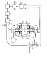
- Light 1 having a suitable wavelength for spectroscopic gas analysis is emitted from a light source 2, here a tunable diode laser, which is driven by a laser controller 3.
- the laser controller 3 controls the injection current and/or the temperature of the diode laser 2 according to information provided by a computer 4 so as to continuously vary the wavelength of the emitted light 1 over a desired wavelength range for analysis.
- the light 1 is split by means of an optical coupler 5 into a first portion 6 for passing through a measuring volume 7 and a second portion 8 for passing through a compensation volume 9.
- the measuring volume 7 is part of a gas pipe 10 through which a process gas, the measuring gas 11, flows.
- the measuring gas 11 may be chlorine, the moisture content of which has to be determined.
- Two flange tubes 12 and 13 are welded at diametrically opposed positions into the wall of the gas pipe 10.
- a transmitter unit 14 and a receiver unit 15 are mounted to the respective flange tubes 12 and 13, the interiors of the units 14 and 15 being separated from the interior of the gas pipe 10 by optical windows 16 and 17.
- the first light portion 6 is guided by a first fiber optic cable 18 from the optical coupler 5 to the transmitter unit 14.
- the interior of the transmitter unit 14 is connected to a purge gas source 21 for flushing the sections of the first optical path 19 running through the units 14 and 15 with a purge gas 22 such as nitrogen, thus defining the remaining unpurged section within the gas pipe 10 as the measurement path length.
- a purge gas 22 such as nitrogen
- the purge gas 22 is conducted from the interior of the transmitter unit 14 to the interior of the receiver unit 15 by means of a gas feed line 23.
- the optical path sections to be purged can be flushed in other, different orders and directions.
- the purge gas 22 is transferred via a further gas feed line 24 to and conducted through the compensation volume 9, here a compensation cell having a predetermined optical path length.
- the second light portion 8 is guided by a second fiber optic cable 25 from the optical coupler 5 to the compensation volume 9, where it is transmitted along a second optical path 26 through the compensation volume 9 to a compensation detector 27.
- the wavelength of the light 1 of the light source 2 is continuously scanned over a characteristic absorption line of the trace gas component to be measured, here water vapor.
- the measuring detector output 28 contains the wavelength-specific light absorption of the moisture content of both the measuring gas 11 and the purge gas 22, whereas the compensation detector output 29 only contains the light absorption of the moisture content of the purge gas 22.
- the detector outputs 28 and 29 are fed to an evaluation means 30 which determines the moisture content of the measuring gas from the difference between the measuring detector output 28 and the compensation detector output 29. The determined moisture content is then provided via an output 31 of the computer 4 for displaying or further processing.
- a portion of the purge gas 22 coming from the gas source 21 can be fed into the respective interiors of the flange tubes 12 and 13.
- the purge gas flow helps to remove measuring gas 11 from dead areas and to keep the optical windows 16 and 17 cool and clean, the latter by preventing the windows 16 and 17 from coming into contact with dust and furnace-off gases flowing through the gas pipe 10.
- a beam splitter might split the light 1 of the light source 2 into a first light beam passing through the measuring volume 7 and a second light beam for passing through the compensation volume 9.
- the invention can be applied to other known absorption-based measuring principles.
Landscapes
- Physics & Mathematics (AREA)
- Spectroscopy & Molecular Physics (AREA)
- Health & Medical Sciences (AREA)
- Life Sciences & Earth Sciences (AREA)
- Chemical & Material Sciences (AREA)
- Analytical Chemistry (AREA)
- Biochemistry (AREA)
- General Health & Medical Sciences (AREA)
- General Physics & Mathematics (AREA)
- Immunology (AREA)
- Pathology (AREA)
- Optics & Photonics (AREA)
- Investigating Or Analysing Materials By Optical Means (AREA)
Abstract
Description
- The invention relates to a method for quantitatively determining a trace gas component in a measuring gas.
- It further relates to a corresponding apparatus.
- In spectroscopic trace gas detection, the concentration of a known gas component, or gas components, in a gas mixture (measuring gas) is determined from a measured wavelength-specific absorption of the gas component or a measured absorption spectrum of the measuring gas, respectively. For this purpose, the measuring gas is introduced in a measuring volume having a predetermined optical measurement path length, e. g. a sample cell or, in case of in-situ process measurements, a gas-leading pipe, furnace, funnel or the like. The light of a light source, e. g. an infrared lamp or a tunable diode laser, is transmitted through the measuring volume to a measuring detector, e. g. an opto-pneumatic or solid-state detector, for generating a measuring detector output dependent on the light absorption in the optical path of the measuring volume. In dual-cell or dual-beam devices, a portion of the light of the light source is passed through a reference cell comprising the known gas component or another suitable gas component of constant concentration. Afterwards the light is detected by a reference detector, the output of which is used for self-calibration and zero point determination of the system.
- Trace gas detection in a measuring gas with high precision and sensitivity is very difficult if the main ingredient or ingredients of the measuring gas and the trace gas component to be measured absorb light at identical wavelengths and if the amount of absorption by the main ingredient is greater than that by the trace gas component. An example is the quantitative analysis of moisture (water vapor) in process gases like ammonia or nitrogen. To eliminate such interfering absorption, it has been proposed in US 6,040,914 to introduce into the reference cell a cancel gas consisting of the main ingredient of the measuring gas without the trace gas component, e. g. dry ammonia or dry nitrogen, and to subtract the absorption spectrum of the cancel gas from the absorption spectrum of the measuring gas by subtracting the output of the reference detector from the output of the measuring detector.
- From US 6,635,875 a gas analyzer for leak detection is known, wherein a gas sample is taken by a sampling probe and led into an infrared sample cell, where the light absorption of the gas sample is measured. As the sampling probe not only collects gases escaping from a possibly existing leak but also gases from the environment of the probe, atmospheric gases from the environment of the sampling probe's tip are taken by an additional reference probe and fed into a reference cell, where the light absorption of the atmospheric gases is measured. By subtracting the measured light absorption of the atmospheric gases from the measured absorption of the gas sample, a proper leak detection is achieved.
- In spectroscopic devices, such as known from US 5,117,561, the optical path from the light source to the measuring volume and from there to the measuring detector is often sealed off from the ambient atmosphere and purged with a purge gas such as dry nitrogen to prevent penetration of atmospheric gas components, e. g. water vapor, which may interfere with the trace gas measurement. The moisture content in the nitrogen supply is usually in the range of a few ppm at the gas source and can increase dramatically at the measuring site depending on the length of the nitrogen pipe net and due to porosity of the pipe walls, leakage of the seals and residual moisture trapped in so-called dead legs.
- Therefore, the invention seeks to provide a trace gas detection method and apparatus which compensate interfering absorption of atmospheric gas components and other impurities in the purge gas.
- According to the invention this is achieved by the method defined in claim 1 and the apparatus defined in
claim 4. - Preferred embodiments of the method and apparatus according to the invention are specified in the remaining claims.
- In accordance with the invention the light absorption of the purge gas after purging the optical path from the light source to the measuring volume and from there to the measuring detector is measured and subtracted from the measured light absorption of the measuring gas. Thus, any offset in the quantitatively determined trace gas level caused by impurities in the purge gas will be automatically and in real-time compensated. By this means the trace gas detection limit and accuracy are significantly improved. Additionally, the compensation is effective even in cases when the pressure and absorption line broadening in the measuring gas and in the purge gas are different.
- In order to improve the accuracy of the measurement the measured light absorptions of the measuring gas and the purge gas are adjusted prior to their subtraction by means of a scaling factor, which depends on the ratio of the purged optical path length in the measuring volume and the purged length of the second optical path and which can be obtained from design data of the apparatus or can be measured when the measuring volume is filled with the purge gas.
- The invention will be now described by way of a preferred example and with reference to the only figure of the drawing.
- Light 1 having a suitable wavelength for spectroscopic gas analysis is emitted from a
light source 2, here a tunable diode laser, which is driven by alaser controller 3. Thelaser controller 3 controls the injection current and/or the temperature of thediode laser 2 according to information provided by acomputer 4 so as to continuously vary the wavelength of the emitted light 1 over a desired wavelength range for analysis. The light 1 is split by means of anoptical coupler 5 into a first portion 6 for passing through ameasuring volume 7 and a second portion 8 for passing through acompensation volume 9. - In the shown example the
measuring volume 7 is part of agas pipe 10 through which a process gas, themeasuring gas 11, flows. Themeasuring gas 11 may be chlorine, the moisture content of which has to be determined. Twoflange tubes gas pipe 10. Atransmitter unit 14 and areceiver unit 15 are mounted to therespective flange tubes units gas pipe 10 byoptical windows optical coupler 5 to thetransmitter unit 14. From there the first light portion 6 is transmitted along a firstoptical path 19 through theflange tubes volume 7 to thereceiving unit 15, where it impinges onto ameasuring detector 20. The interior of thetransmitter unit 14 is connected to apurge gas source 21 for flushing the sections of the firstoptical path 19 running through theunits purge gas 22 such as nitrogen, thus defining the remaining unpurged section within thegas pipe 10 as the measurement path length. For this purpose thepurge gas 22 is conducted from the interior of thetransmitter unit 14 to the interior of thereceiver unit 15 by means of agas feed line 23. Of course the optical path sections to be purged can be flushed in other, different orders and directions. - After flushing the first optical path sections the
purge gas 22 is transferred via a furthergas feed line 24 to and conducted through thecompensation volume 9, here a compensation cell having a predetermined optical path length. The second light portion 8 is guided by a second fiber optic cable 25 from theoptical coupler 5 to thecompensation volume 9, where it is transmitted along a secondoptical path 26 through thecompensation volume 9 to acompensation detector 27. - The wavelength of the light 1 of the
light source 2 is continuously scanned over a characteristic absorption line of the trace gas component to be measured, here water vapor. Thus, themeasuring detector output 28 contains the wavelength-specific light absorption of the moisture content of both themeasuring gas 11 and thepurge gas 22, whereas thecompensation detector output 29 only contains the light absorption of the moisture content of thepurge gas 22. The detector outputs 28 and 29 are fed to an evaluation means 30 which determines the moisture content of the measuring gas from the difference between themeasuring detector output 28 and thecompensation detector output 29. The determined moisture content is then provided via an output 31 of thecomputer 4 for displaying or further processing. - As indicated by
dotted lines 32, a portion of thepurge gas 22 coming from thegas source 21 can be fed into the respective interiors of theflange tubes gas 11 from dead areas and to keep theoptical windows windows gas pipe 10. - Many other modifications and variations of the invention are possible in view of the above disclosure. So instead of the optical coupler 5 a beam splitter might split the light 1 of the
light source 2 into a first light beam passing through themeasuring volume 7 and a second light beam for passing through thecompensation volume 9. Furthermore, the invention can be applied to other known absorption-based measuring principles.
Claims (4)
- Method for quantitatively determining a trace gas component in a measuring gas (11), comprising the steps of:- introducing the measuring gas (11) into a measuring volume (7) ;- emitting light (1) from a light source (2);- passing a first portion (6) of the light (1) along a first optical path (19) from the light source (2) through the measuring volume (7) to a measuring detector (20);- generating a measuring detector output (28) dependent on the light absorption in the first optical path (19);- flushing sections of the first optical path (19) between the light source (2) and the measuring volume (7) and the measuring volume (7) and the measuring detector (20) with a purge gas (22);- collecting the purge gas (22) after flushing the first optical path sections;- transmitting a second portion (8) of the light (1) along a second optical path (26) from the light source (2) to a compensation detector (27);- flushing the second optical path (26) with the collected purge gas (22);- generating a compensation detector output (29) dependent on the light absorption in the second optical path (26); and- determining the trace gas component in the measuring gas (11) based on a difference between the measuring detector output (28) and the compensation detector output (29).
- The method of claim 1 further comprising the step of:- varying the frequency of the light (1) of the light source (2) over a frequency spectrum including an absorption frequency of the trace gas component.
- The method of claim 1 or 2 further comprising the step of:- prior to determining the trace gas component adjusting the ratio of the measuring and compensation detector outputs (28, 29) by means of a scaling factor, wherein said scaling factor depends on the ratio of the purged optical path length in the measuring volume (7) and the purged length of the second optical path (26).
- Apparatus for quantitatively determining a trace gas component in a measuring gas (11), comprising:- a measuring volume (7) configured to contain the measuring gas (11);- a light source (2);- means (5) for obtaining a first portion (6) and a second portion (8) of the light (1) from the light source (2);- a measuring detector (20) for generating a measuring detector output (28);- means for passing the first light portion (6) along a first optical path (19) through the measuring volume (7) to the measuring detector (20);- a compensation detector (27) for generating a compensation detector output (29);- means for transmitting the second light portion (8) along a second optical path (26) to the compensation detector (27);- means (21) for providing a purge gas (22);- means (21, 23) for flushing sections of the first optical path (19) between the light source (2) and the measuring volume (7) and the measuring volume (7) and the measuring detector (20) with the purge gas (22);- means (24) for collecting the purge gas (22) after flushing the first optical path sections;- means for flushing the second optical path (26) with the collected purge gas (22); and- evaluation means (30) for determining the trace gas component in the measuring gas (11) based on a difference between the measuring detector output (28) and the compensation detector output (29).
Priority Applications (3)
| Application Number | Priority Date | Filing Date | Title |
|---|---|---|---|
| EP05003771A EP1693665B1 (en) | 2005-02-22 | 2005-02-22 | Method and apparatus for trace gas detection |
| DE602005011398T DE602005011398D1 (en) | 2005-02-22 | 2005-02-22 | Method and device for detecting trace gases |
| US11/358,854 US7324204B2 (en) | 2005-02-22 | 2006-02-21 | Method and apparatus for trace gas detection |
Applications Claiming Priority (1)
| Application Number | Priority Date | Filing Date | Title |
|---|---|---|---|
| EP05003771A EP1693665B1 (en) | 2005-02-22 | 2005-02-22 | Method and apparatus for trace gas detection |
Publications (2)
| Publication Number | Publication Date |
|---|---|
| EP1693665A1 true EP1693665A1 (en) | 2006-08-23 |
| EP1693665B1 EP1693665B1 (en) | 2008-12-03 |
Family
ID=34933876
Family Applications (1)
| Application Number | Title | Priority Date | Filing Date |
|---|---|---|---|
| EP05003771A Active EP1693665B1 (en) | 2005-02-22 | 2005-02-22 | Method and apparatus for trace gas detection |
Country Status (3)
| Country | Link |
|---|---|
| US (1) | US7324204B2 (en) |
| EP (1) | EP1693665B1 (en) |
| DE (1) | DE602005011398D1 (en) |
Cited By (13)
| Publication number | Priority date | Publication date | Assignee | Title |
|---|---|---|---|---|
| EP2169385A1 (en) | 2008-09-24 | 2010-03-31 | Siemens Aktiengesellschaft | An optical measuring head for a duct gas monitoring system |
| DE102009058394B3 (en) * | 2009-12-15 | 2011-02-10 | Siemens Aktiengesellschaft | Method for measuring the concentration of at least one gas component in a sample gas |
| CN101672778B (en) * | 2009-08-20 | 2011-05-18 | 聚光科技(杭州)股份有限公司 | Method and device for detecting water quality |
| WO2011066868A1 (en) * | 2009-12-04 | 2011-06-09 | Siemens Aktiengesellschaft | Method for determining the optical measurement path length in a duct gas monitoring system |
| US8074492B2 (en) * | 2006-04-10 | 2011-12-13 | Robert Brockmann | Method and apparatus for the detection of leaks |
| CN102564994A (en) * | 2011-12-31 | 2012-07-11 | 聚光科技(杭州)股份有限公司 | In-place gas measurement method and in-place gas measurement device |
| FR3019772A1 (en) * | 2014-04-14 | 2015-10-16 | Fondarex Sa | DEVICE AND METHOD FOR MEASURING HUMIDITY IN PRESSURE CASTING MOLDS |
| CN105158191A (en) * | 2015-09-01 | 2015-12-16 | 中国科学院合肥物质科学研究院 | Concentration detecting device for arsenic trioxide gas in arsenic-containing gold concentrate roasting furnace |
| EP3104163A1 (en) * | 2015-06-12 | 2016-12-14 | Siemens Aktiengesellschaft | Process gas analyser and method for analyzing a process gas |
| WO2016207186A1 (en) * | 2015-06-22 | 2016-12-29 | Avl Ditest Gmbh | Measuring apparatus and measuring method for monitoring the drift of optical systems |
| CN108181265A (en) * | 2017-12-14 | 2018-06-19 | 北京航天易联科技发展有限公司 | A kind of binary channels low concentration aqueous vapor high precision measuring device and method |
| EP3364169A1 (en) | 2017-02-17 | 2018-08-22 | Siemens Aktiengesellschaft | Process gas analyser |
| EP3680644A1 (en) * | 2019-01-08 | 2020-07-15 | Sick Ag | Analyzing apparatus |
Families Citing this family (12)
| Publication number | Priority date | Publication date | Assignee | Title |
|---|---|---|---|---|
| US7132661B2 (en) * | 2000-08-28 | 2006-11-07 | Spectrasensors, Inc. | System and method for detecting water vapor within natural gas |
| US7679059B2 (en) * | 2006-04-19 | 2010-03-16 | Spectrasensors, Inc. | Measuring water vapor in hydrocarbons |
| US7511802B2 (en) | 2006-05-26 | 2009-03-31 | Spectrasensors, Inc. | Measuring trace components of complex gases using gas chromatography/absorption spectrometry |
| DE102006055157B3 (en) * | 2006-11-22 | 2008-04-30 | Siemens Ag | Optical measuring cell for use in gas monitor, has light source for transferring light into measuring volume that is represented by inner volume of hollow fiber whose inner diameter is less than 1 millimeter |
| US7508521B2 (en) * | 2007-03-14 | 2009-03-24 | Spectrasensors, Inc. | Pressure-invariant trace gas detection |
| WO2008128114A1 (en) * | 2007-04-11 | 2008-10-23 | Spectrasensors, Inc. | Reactive gas detection in complex backgrounds |
| US8040518B2 (en) * | 2008-10-07 | 2011-10-18 | Entanglement Technologies, Inc. | Cavity enhanced trace gas detection gradiometer |
| US8848190B2 (en) * | 2012-06-21 | 2014-09-30 | Honeywell Asca Inc. | Sensor for early detection of problems in algae cultures and related system and method |
| US10643008B2 (en) | 2014-11-11 | 2020-05-05 | Spectrasensors, Inc. | Target analyte detection and quantification in sample gases with complex background compositions |
| CN107505286A (en) * | 2017-09-22 | 2017-12-22 | 中国烟草总公司郑州烟草研究院 | Oxygen consumption amount detecting device and detection method during a kind of cigarette is burnt and sucked |
| JP7013924B2 (en) * | 2018-02-20 | 2022-02-01 | 宇部興産株式会社 | Oxygen concentration measuring device and oxygen concentration measuring method |
| CN109696417A (en) * | 2019-02-01 | 2019-04-30 | 清华大学 | A kind of measuring system of the line parameters based on gas absorption spectra |
Citations (2)
| Publication number | Priority date | Publication date | Assignee | Title |
|---|---|---|---|---|
| US5747809A (en) * | 1996-06-11 | 1998-05-05 | Sri International | NDIR apparatus and method for measuring isotopic ratios in gaseous samples |
| EP1092971A2 (en) * | 1999-10-15 | 2001-04-18 | Li-Cor, Inc. | Gas analyzer |
Family Cites Families (10)
| Publication number | Priority date | Publication date | Assignee | Title |
|---|---|---|---|---|
| US4583859A (en) * | 1984-03-30 | 1986-04-22 | The Babcock & Wilcox Company | Filter cleaning system for opacity monitor |
| US5177561A (en) * | 1990-06-29 | 1993-01-05 | Harrick Scientific Corp. | Purging of optical spectrometer accessories |
| SE508805C2 (en) * | 1991-12-04 | 1998-11-09 | Opsis Ab | Optical analysis equipment - analyses gas-form substances flowing through channel and incorporates light transmitter on channel side and light receiver on other channel side |
| ATE271218T1 (en) * | 1997-01-14 | 2004-07-15 | Otsuka Pharma Co Ltd | DEVICE AND METHOD FOR MEASURING STABLE ISOTOPES USING SPECTROSCOPY |
| JPH10281988A (en) * | 1997-04-09 | 1998-10-23 | Nippon Sanso Kk | Method and device for gas analysis |
| US6040914A (en) * | 1997-06-10 | 2000-03-21 | New Focus, Inc. | Simple, low cost, laser absorption sensor system |
| WO1999053297A1 (en) * | 1998-04-14 | 1999-10-21 | Instrumentarium Corporation | Sensor assembly and method for measuring nitrogen dioxide |
| DE19911260A1 (en) * | 1999-03-13 | 2000-09-14 | Leybold Vakuum Gmbh | Infrared gas analyzer and method for operating this analyzer |
| US20050122523A1 (en) * | 2003-12-03 | 2005-06-09 | Wen-Bin Yan | Device and method of trace gas analysis using cavity ring-down spectroscopy |
| EP1544604B1 (en) * | 2003-12-17 | 2017-09-27 | Siemens Aktiengesellschaft | Wavelength modulation spectroscopy method |
-
2005
- 2005-02-22 DE DE602005011398T patent/DE602005011398D1/en active Active
- 2005-02-22 EP EP05003771A patent/EP1693665B1/en active Active
-
2006
- 2006-02-21 US US11/358,854 patent/US7324204B2/en active Active
Patent Citations (2)
| Publication number | Priority date | Publication date | Assignee | Title |
|---|---|---|---|---|
| US5747809A (en) * | 1996-06-11 | 1998-05-05 | Sri International | NDIR apparatus and method for measuring isotopic ratios in gaseous samples |
| EP1092971A2 (en) * | 1999-10-15 | 2001-04-18 | Li-Cor, Inc. | Gas analyzer |
Cited By (22)
| Publication number | Priority date | Publication date | Assignee | Title |
|---|---|---|---|---|
| US8074492B2 (en) * | 2006-04-10 | 2011-12-13 | Robert Brockmann | Method and apparatus for the detection of leaks |
| EP2169385A1 (en) | 2008-09-24 | 2010-03-31 | Siemens Aktiengesellschaft | An optical measuring head for a duct gas monitoring system |
| US8274658B2 (en) | 2008-09-24 | 2012-09-25 | Siemens Aktiengesellschaft | Optical measuring head for a duct gas monitoring system |
| CN101672778B (en) * | 2009-08-20 | 2011-05-18 | 聚光科技(杭州)股份有限公司 | Method and device for detecting water quality |
| WO2011066868A1 (en) * | 2009-12-04 | 2011-06-09 | Siemens Aktiengesellschaft | Method for determining the optical measurement path length in a duct gas monitoring system |
| CN102639983A (en) * | 2009-12-04 | 2012-08-15 | 西门子公司 | Method for determining the optical measurement path length in a duct gas monitoring system |
| US8830470B2 (en) | 2009-12-15 | 2014-09-09 | Siemens Aktiengesellschaft | Method for measuring the concentration of at least one gas component in a measuring gas |
| DE102009058394B3 (en) * | 2009-12-15 | 2011-02-10 | Siemens Aktiengesellschaft | Method for measuring the concentration of at least one gas component in a sample gas |
| WO2011082925A1 (en) | 2009-12-15 | 2011-07-14 | Siemens Aktiengesellschaft | Method for measuring the concentration of at least one gas component in a measuring gas |
| CN102564994B (en) * | 2011-12-31 | 2014-12-24 | 聚光科技(杭州)股份有限公司 | In-place gas measurement method and in-place gas measurement device |
| CN102564994A (en) * | 2011-12-31 | 2012-07-11 | 聚光科技(杭州)股份有限公司 | In-place gas measurement method and in-place gas measurement device |
| FR3019772A1 (en) * | 2014-04-14 | 2015-10-16 | Fondarex Sa | DEVICE AND METHOD FOR MEASURING HUMIDITY IN PRESSURE CASTING MOLDS |
| NL2014610A (en) * | 2014-04-14 | 2016-03-08 | Fondarex Sa | Device and Method for Measuring the Moisture in Die Casting Molds. |
| DK178950B1 (en) * | 2014-04-14 | 2017-06-26 | Fondarex Sa | Device and method for measuring the moisture in die casting molds |
| EP3104163A1 (en) * | 2015-06-12 | 2016-12-14 | Siemens Aktiengesellschaft | Process gas analyser and method for analyzing a process gas |
| US9927357B2 (en) | 2015-06-12 | 2018-03-27 | Siemens Aktiengesellschaft | Process gas analyzer and method for analyzing a process gas |
| WO2016207186A1 (en) * | 2015-06-22 | 2016-12-29 | Avl Ditest Gmbh | Measuring apparatus and measuring method for monitoring the drift of optical systems |
| CN105158191A (en) * | 2015-09-01 | 2015-12-16 | 中国科学院合肥物质科学研究院 | Concentration detecting device for arsenic trioxide gas in arsenic-containing gold concentrate roasting furnace |
| CN105158191B (en) * | 2015-09-01 | 2018-02-06 | 中国科学院合肥物质科学研究院 | The concentration detection apparatus of arsenic trioxide gas in the roaster of gold concentrate containing arsenic |
| EP3364169A1 (en) | 2017-02-17 | 2018-08-22 | Siemens Aktiengesellschaft | Process gas analyser |
| CN108181265A (en) * | 2017-12-14 | 2018-06-19 | 北京航天易联科技发展有限公司 | A kind of binary channels low concentration aqueous vapor high precision measuring device and method |
| EP3680644A1 (en) * | 2019-01-08 | 2020-07-15 | Sick Ag | Analyzing apparatus |
Also Published As
| Publication number | Publication date |
|---|---|
| US7324204B2 (en) | 2008-01-29 |
| DE602005011398D1 (en) | 2009-01-15 |
| EP1693665B1 (en) | 2008-12-03 |
| US20060192967A1 (en) | 2006-08-31 |
Similar Documents
| Publication | Publication Date | Title |
|---|---|---|
| US7324204B2 (en) | Method and apparatus for trace gas detection | |
| US6157033A (en) | Leak detection system | |
| KR101454007B1 (en) | Leak Detection System and Method | |
| US9194797B2 (en) | Method and system for detecting moisture in a process gas involving cross interference | |
| EP3049806B1 (en) | Method and system for gas concentration measurement of gas dissolved in liquids | |
| KR20010021565A (en) | Method for calibration of a spectroscopic sensor | |
| JP6987066B2 (en) | How to Quantify the Amount of Photocoherent Gas Impurities | |
| CN110057779B (en) | Method and device for measuring gas concentration based on temperature automatic compensation TDLAS technology | |
| US20140022542A1 (en) | Gas Analyzer | |
| US9927357B2 (en) | Process gas analyzer and method for analyzing a process gas | |
| KR100910871B1 (en) | Method and apparatus for measuring water contained in the chimney gas | |
| Pierce et al. | Cavity ring-down spectroscopy sensor development for high-time-resolution measurements of gaseous elemental mercury in ambient air | |
| JP4048139B2 (en) | Concentration measuring device | |
| US4733084A (en) | Method of detection and quantitative determination of sulfur and sulfur monitor using the method | |
| JP3858844B2 (en) | Gas monitoring apparatus and gas monitoring method for underground fixation of carbon dioxide gas | |
| CN102656440B (en) | Method for measuring the concentration of at least one gas component in a measuring gas | |
| JP2003222591A (en) | Gas measurement device | |
| KR20170025836A (en) | Gas monitoring system that automatically compensate for water | |
| EP0094706A2 (en) | Gas analyser | |
| JP4671607B2 (en) | Gas component measuring device and exhaust gas discharge facility | |
| JPH09182740A (en) | Biological photomeasuring device | |
| KR100372310B1 (en) | Method for spectral analysis of gas by using laser light | |
| Cheng-Hsien et al. | Sources of error in open-path FTIR measurements of N2O and CO2 emitted from agricultural fields | |
| CN118776994A (en) | Tail gas analysis method and tail gas analysis system | |
| Cocola et al. | Tunable Diode Laser Absorption Spectroscopy applied to gas sensing for agro-food and medical processes |
Legal Events
| Date | Code | Title | Description |
|---|---|---|---|
| PUAI | Public reference made under article 153(3) epc to a published international application that has entered the european phase |
Free format text: ORIGINAL CODE: 0009012 |
|
| 17P | Request for examination filed |
Effective date: 20060220 |
|
| AK | Designated contracting states |
Kind code of ref document: A1 Designated state(s): AT BE BG CH CY CZ DE DK EE ES FI FR GB GR HU IE IS IT LI LT LU MC NL PL PT RO SE SI SK TR |
|
| AX | Request for extension of the european patent |
Extension state: AL BA HR LV MK YU |
|
| AKX | Designation fees paid |
Designated state(s): DE FR GB |
|
| APBN | Date of receipt of notice of appeal recorded |
Free format text: ORIGINAL CODE: EPIDOSNNOA2E |
|
| APBR | Date of receipt of statement of grounds of appeal recorded |
Free format text: ORIGINAL CODE: EPIDOSNNOA3E |
|
| APBV | Interlocutory revision of appeal recorded |
Free format text: ORIGINAL CODE: EPIDOSNIRAPE |
|
| GRAP | Despatch of communication of intention to grant a patent |
Free format text: ORIGINAL CODE: EPIDOSNIGR1 |
|
| GRAS | Grant fee paid |
Free format text: ORIGINAL CODE: EPIDOSNIGR3 |
|
| GRAA | (expected) grant |
Free format text: ORIGINAL CODE: 0009210 |
|
| AK | Designated contracting states |
Kind code of ref document: B1 Designated state(s): DE FR GB |
|
| REG | Reference to a national code |
Ref country code: GB Ref legal event code: FG4D |
|
| REF | Corresponds to: |
Ref document number: 602005011398 Country of ref document: DE Date of ref document: 20090115 Kind code of ref document: P |
|
| PLBE | No opposition filed within time limit |
Free format text: ORIGINAL CODE: 0009261 |
|
| STAA | Information on the status of an ep patent application or granted ep patent |
Free format text: STATUS: NO OPPOSITION FILED WITHIN TIME LIMIT |
|
| 26N | No opposition filed |
Effective date: 20090904 |
|
| PGFP | Annual fee paid to national office [announced via postgrant information from national office to epo] |
Ref country code: GB Payment date: 20130213 Year of fee payment: 9 Ref country code: FR Payment date: 20130301 Year of fee payment: 9 |
|
| GBPC | Gb: european patent ceased through non-payment of renewal fee |
Effective date: 20140222 |
|
| REG | Reference to a national code |
Ref country code: FR Ref legal event code: ST Effective date: 20141031 |
|
| PG25 | Lapsed in a contracting state [announced via postgrant information from national office to epo] |
Ref country code: FR Free format text: LAPSE BECAUSE OF NON-PAYMENT OF DUE FEES Effective date: 20140228 Ref country code: GB Free format text: LAPSE BECAUSE OF NON-PAYMENT OF DUE FEES Effective date: 20140222 |
|
| PGFP | Annual fee paid to national office [announced via postgrant information from national office to epo] |
Ref country code: DE Payment date: 20240418 Year of fee payment: 20 |