EP1693239A2 - Air intake duct for vehicle - Google Patents
Air intake duct for vehicle Download PDFInfo
- Publication number
- EP1693239A2 EP1693239A2 EP06003020A EP06003020A EP1693239A2 EP 1693239 A2 EP1693239 A2 EP 1693239A2 EP 06003020 A EP06003020 A EP 06003020A EP 06003020 A EP06003020 A EP 06003020A EP 1693239 A2 EP1693239 A2 EP 1693239A2
- Authority
- EP
- European Patent Office
- Prior art keywords
- intake duct
- upper support
- linear portion
- air cleaner
- radiator
- Prior art date
- Legal status (The legal status is an assumption and is not a legal conclusion. Google has not performed a legal analysis and makes no representation as to the accuracy of the status listed.)
- Granted
Links
- 239000013013 elastic material Substances 0.000 claims description 12
- 239000004743 Polypropylene Substances 0.000 claims description 8
- 229920001155 polypropylene Polymers 0.000 claims description 8
- -1 polypropylene Polymers 0.000 claims description 5
- 229920002943 EPDM rubber Polymers 0.000 claims description 3
- 229920000181 Ethylene propylene rubber Polymers 0.000 claims description 3
- 239000000463 material Substances 0.000 abstract description 4
- 229920001971 elastomer Polymers 0.000 description 8
- 239000000806 elastomer Substances 0.000 description 4
- 238000002485 combustion reaction Methods 0.000 description 3
- 239000004698 Polyethylene Substances 0.000 description 2
- 238000000034 method Methods 0.000 description 2
- 229920000573 polyethylene Polymers 0.000 description 2
- 229920003002 synthetic resin Polymers 0.000 description 2
- 239000000057 synthetic resin Substances 0.000 description 2
- 238000013459 approach Methods 0.000 description 1
- 238000000071 blow moulding Methods 0.000 description 1
- 230000000694 effects Effects 0.000 description 1
- 238000010102 injection blow moulding Methods 0.000 description 1
- 238000001746 injection moulding Methods 0.000 description 1
- 238000000465 moulding Methods 0.000 description 1
- 229920005989 resin Polymers 0.000 description 1
- 239000011347 resin Substances 0.000 description 1
- 230000035939 shock Effects 0.000 description 1
Images

Classifications
-
- B—PERFORMING OPERATIONS; TRANSPORTING
- B60—VEHICLES IN GENERAL
- B60K—ARRANGEMENT OR MOUNTING OF PROPULSION UNITS OR OF TRANSMISSIONS IN VEHICLES; ARRANGEMENT OR MOUNTING OF PLURAL DIVERSE PRIME-MOVERS IN VEHICLES; AUXILIARY DRIVES FOR VEHICLES; INSTRUMENTATION OR DASHBOARDS FOR VEHICLES; ARRANGEMENTS IN CONNECTION WITH COOLING, AIR INTAKE, GAS EXHAUST OR FUEL SUPPLY OF PROPULSION UNITS IN VEHICLES
- B60K13/00—Arrangement in connection with combustion air intake or gas exhaust of propulsion units
- B60K13/02—Arrangement in connection with combustion air intake or gas exhaust of propulsion units concerning intake
Definitions
- An engine room provided for example in an automobile or similar vehicle for example at a front location accommodates an engine, a radiator and accessories (e.g., an alternator, a cooler compressor, a power steering, and the like) associated with the engine.
- a radiator e.g., an alternator, a cooler compressor, a power steering, and the like
- the engine has an intake system and an exhaust system attached thereto to supply air or the like to a combustion chamber and exhaust gas from the combustion chamber, respectively.
- the intake system at least has an intake duct taking in external air, an air cleaner removing foreign matters contained in the air, and the like.
- Intake duct is formed of polyethylene (PE) or polypropylene (PP) or a similar, relatively hard synthetic resin for example by injection-molding or blow-molding or similar molding.
- PE polyethylene
- PP polypropylene
- the engine's compartment may be increased in size or the equipment may be modified in layout. It is different, however, to adopt such approaches, since some designs prevent an engine from having a compartment increased in size and there are also constraints on modifying the equipment in arrangement.
- the present invention contemplates an arrangement for a vehicular intake duct that can prevent equipment in an engine room from significant damage or protect it against damage if the vehicle has a front portion slightly bumping into an object.
- the present invention provides an arrangement in which in a vehicle's body internal to an engine room at a location inner than a radiator's upper support an air cleaner is situated separate from and opposite to the upper support in a fore-aft direction of the body and between the air cleaner and the upper support an intake duct is situated to introduce external air into the air cleaner, characterized in that: the intake duct has a linear portion extending in a longitudinal direction of the upper support, and overlapping the upper support, as seen from a front side of the body in projective view; and the intake duct at least has the linear portion formed of an elastic material.
- the intake duct having the linear portion extending along the upper support or in the direction of the width of the body allows designing a structure ensuring that air is taken in efficiently and vibration and noise characteristics are ensured, i.e., the intake duct can be increased in length and diameter as soon as possible. Furthermore, the intake duct that does not overlie the radiator's upper support allows the body to have a front portion designed to be reduced in height and hence designed with an increased degree of freedom.
- the intake duct is entirely formed of the elastic material.
- the intake duct can be elastically deformed and thus help an operation attaching the same.
- the intake duct can have the linear portion with one end serving as an inlet introducing external air, and also have an intermediate portion closer to the other end of the liner portion and extending downward, and a connection extending from the intermediate portion rearward and connected to the air cleaner.
- This configuration illustrates a general geometry of the intake duct in an example and is advantageous when the engine room has a relatively small size in the fore-aft direction of the vehicle's body.
- This embodiment exemplifies a type of automobile or similar vehicle having a body 1 having a front portion provided with an engine room 2.
- engine room 2 accommodates an engine 3 as a matter of course, and a radiator 4, an intercooler 5, an air cleaner 6, a battery 7 and other similar equipment associated with engine 3.
- body 1 is assumed as including an engine hood and a bumper cover.
- a reference character 1a denotes a front bumper and reference characters 1b and 1c denote front side members.
- Radiator 4 is situated in engine room 2 under the radiator's upper support 8 arranged in body 1 at a front upper location.
- Intercooler 5 underlies the radiator's upper support 8 adjacent to radiator 4.
- Air cleaner 6 and battery 7 are situated in engine room 2 adjacent to one side of engine 3. Air cleaner 6 is situated inner than the radiator's upper support 8, separate therefrom and opposite thereto as seen in the fore-aft direction of body 1, and battery 7 is arranged behind air cleaner 6.
- Air cleaner 6 has an air inlet with an intake duct 10 attached thereto.
- Intake duct 10 introduces external air into air cleaner 6 and as shown in Fig. 2 it is located between the radiator's upper support 8 and air cleaner 6.
- intake duct 10 has a linear portion 11 extending along the radiator's upper support 8 or the body's width with one end serving as an inlet 11a introducing external air, an intermediate portion 12 located closer to the other end of linear portion 11 and extending downward, and a connection 13 extending from intermediate portion 12 rearward to connect to air cleaner 6.
- Intake duct 10 has linear portion 11 situated to overlap the radiator's upper support 8, as seen from a front side of body 1 in projective view.
- Intake duct 10 thus provided is entirely formed of an elastic material. More specifically, intake duct 10 is suitably formed of a material implemented by an elastic material including an elastomer formed of polypropylene (PP) and ethylene-propylene rubber (EPDM) mixed together.
- PP polypropylene
- EPDM ethylene-propylene rubber
- the elastomer serving as a material for intake duct 10 is excellent in that it is not only equivalent to rubber and the like in flexibility, oil resistance, heat resistance, tensile strength and tear strength, but also smaller in weight than rubber and the like and recyclable.
- Such intake duct 10 is formed of the above described elastomer by a generally well known blow molding technique. This technique is well known and will not be described herein.
- intake duct 10 is formed of elastomer and situated in engine room 2 at a front location between the radiator's upper support 8 and air cleaner 6 at a location intermediate as seen in the direction of the width of body 1 such that when intake duct 10 is seen from a front side of body 1 in projective view intake duct 10 overlaps the radiator's upper support 8.
- radiator's upper support 8 slightly bumps into an external object 20 and thus deforms toward engine room 2 by an amount, and together air cleaner 6 compresses intake duct 10 at linear portion 11 in the fore-aft direction of body 1, linear portion 11 does not fracture and is instead only elastically compressed and deformed.
- the present intake duct can reduce the possibility that it will fracture into pieces which in turn thrust into and thus damage radiator 4, intercooler 5 and the like, i.e., cause additional damage.
- the present intake duct can thus contribute to reduced damageability.
- intake duct 10 having linear portion 11 extending in the direction of the width of body 1 allows designing a structure ensuring that air is taken in efficiently and vibration and noise characteristics are ensured, i.e., it can be increased in length and diameter as soon as possible. Furthermore, intake duct 10 that does not overlie the radiator's upper support 8 allows body 1 to have a front portion designed to be reduced in height and hence designed with an increased degree of freedom.
- intake duct 10 is entirely formed of an elastic material. When intake duct 10 is attached to air cleaner 6 intake duct 10 can be elastically deformed and thus help an operation attaching the same.
Landscapes
- Engineering & Computer Science (AREA)
- Chemical & Material Sciences (AREA)
- Combustion & Propulsion (AREA)
- Transportation (AREA)
- Mechanical Engineering (AREA)
- Cooling, Air Intake And Gas Exhaust, And Fuel Tank Arrangements In Propulsion Units (AREA)
Abstract
Description
- This nonprovisional application is based on Japanese Patent Application No. 2005-041379 filed with the Japan Patent Office on February 17, 2005, the entire contents of which are hereby incorporated by reference.
- The present invention relates arrangements for vehicular intake ducts for example introducing external air into engines, and intake ducts.
- An engine room provided for example in an automobile or similar vehicle for example at a front location accommodates an engine, a radiator and accessories (e.g., an alternator, a cooler compressor, a power steering, and the like) associated with the engine.
- The engine has an intake system and an exhaust system attached thereto to supply air or the like to a combustion chamber and exhaust gas from the combustion chamber, respectively. The intake system at least has an intake duct taking in external air, an air cleaner removing foreign matters contained in the air, and the like.
- Generally, to allow an engine to provide combustion more efficiently, fresh and cold air present in front of the engine must be introduced into the engine, and accordingly an intake duct is arranged in the engine room closer to a front side. (See Japanese Patent Laying-open No. 2004-124757.)
- Intake duct is formed of polyethylene (PE) or polypropylene (PP) or a similar, relatively hard synthetic resin for example by injection-molding or blow-molding or similar molding.
- In the above conventional example if the vehicle has a front side slightly bumping into some object the intake duct, which is prone to fracture, fractures and may thus damage equipment (such as a radiator, an intercooler and the like) accommodated in the engine room or cause a similar additional damage which may necessitate an additional cost to repair the damage.
- To avoid this, the engine's compartment may be increased in size or the equipment may be modified in layout. It is different, however, to adopt such approaches, since some designs prevent an engine from having a compartment increased in size and there are also constraints on modifying the equipment in arrangement.
- The present invention contemplates an arrangement for a vehicular intake duct that can prevent equipment in an engine room from significant damage or protect it against damage if the vehicle has a front portion slightly bumping into an object.
- The present invention provides an arrangement in which in a vehicle's body internal to an engine room at a location inner than a radiator's upper support an air cleaner is situated separate from and opposite to the upper support in a fore-aft direction of the body and between the air cleaner and the upper support an intake duct is situated to introduce external air into the air cleaner, characterized in that: the intake duct has a linear portion extending in a longitudinal direction of the upper support, and overlapping the upper support, as seen from a front side of the body in projective view; and the intake duct at least has the linear portion formed of an elastic material.
- If the upper support slightly bumps into an external object and is deformed toward the engine room by an amount, and together the air cleaner compresses the intake duct at the linear portion in the body's fore-aft direction the linear portion can be prevent from fracture and instead only, elastically be compressed and deformed. In contrast to a conventional example having a linear portion fractured, the present arrangement can reduce the possibility that an intake duct will fracture into pieces which in turn thrust into and thus damage the radiator and the like, i.e., cause additional damage. The present arrangement can thus contribute to reduced damageability.
- Furthermore, the intake duct having the linear portion extending along the upper support or in the direction of the width of the body allows designing a structure ensuring that air is taken in efficiently and vibration and noise characteristics are ensured, i.e., the intake duct can be increased in length and diameter as soon as possible. Furthermore, the intake duct that does not overlie the radiator's upper support allows the body to have a front portion designed to be reduced in height and hence designed with an increased degree of freedom.
- Note that the intake duct is entirely formed of the elastic material. When the intake duct is attached to the air cleaner the intake duct can be elastically deformed and thus help an operation attaching the same.
- In the present arrangement the intake duct can have the linear portion with one end serving as an inlet introducing external air, and also have an intermediate portion closer to the other end of the liner portion and extending downward, and a connection extending from the intermediate portion rearward and connected to the air cleaner.
- This configuration illustrates a general geometry of the intake duct in an example and is advantageous when the engine room has a relatively small size in the fore-aft direction of the vehicle's body.
- In the present arrangement the intake duct can at least have the linear portion formed of the elastic material formed of polypropylene (PP) and ethylene-propylene rubber (EPDM) mixed together.
- Among flexible, typical elastic materials, a relatively inexpensively available, such material is selected and used to form the intake duct. This is advantageous in producing the intake duct inexpensively. Furthermore, the above synthetic resin is advantageously smaller in weight than rubber and recyclable while also being equivalent in flexibility, strength and moldablitiy to rubber.
- The present invention provides an intake duct situated between a radiator's upper support of a vehicle's body and an air cleaner located in an engine room of the body at a position inner than the upper support, separate therefrom and opposite thereto as seen in a fore-aft direction of the body, to introduce external air into the air cleaner, characterized by having a linear portion extending in a longitudinal direction of the upper support, and overlapping the upper support, as seen from a front side of the body in projective view, and at least having the linear portion formed of an elastic material.
- The present intake duct can provide a function and effect similar to that of the arrangement for the intake duct as described above.
- In accordance with the present invention if a vehicle has a front portion slightly bumping into an object, equipment in an engine room can be prevented from significant damage or protected against damage. Furthermore, the intake duct can be increased in length as soon as possible, which can contribute to increased efficiency in taking in air, and reduced vibration and noise.
- The foregoing and other objects, features, aspects and advantages of the present invention will become more apparent from the following detailed description of the present invention when taken in conjunction with the accompanying drawings.
-
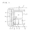
- Fig. 1 is a plan view of one embodiment of an arrangement for an intake duct in accordance with the present invention.
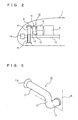
- Fig. 2 is a side view of the Fig. 1 arrangement.
- Fig. 3 is a perspective view of the intake duct of Fig. 1 shown discretely.
- Fig. 4 shows a vehicle having a body slightly bumping into an object in Fig. 1
- Fig. 5 is a side view of another embodiment of the intake duct shown in Fig. 2.
- Hereinafter the present invention in an embodiment will be described with reference to Figs. 1-4. This embodiment exemplifies a type of automobile or similar vehicle having a
body 1 having a front portion provided with anengine room 2. - As shown in Figs. 1 and 2,
engine room 2 accommodates anengine 3 as a matter of course, and aradiator 4, anintercooler 5, anair cleaner 6, abattery 7 and other similar equipment associated withengine 3. Note that the figures do not show accessories such as an alternator, a cooler compressor, a power steering and the like associated withengine 3. Furthermore in thefigures body 1 is assumed as including an engine hood and a bumper cover. Furthermore in the figures areference character 1a denotes a front bumper andreference characters -
Radiator 4 is situated inengine room 2 under the radiator'supper support 8 arranged inbody 1 at a front upper location. Intercooler 5 underlies the radiator'supper support 8 adjacent toradiator 4. -
Air cleaner 6 andbattery 7 are situated inengine room 2 adjacent to one side ofengine 3.Air cleaner 6 is situated inner than the radiator'supper support 8, separate therefrom and opposite thereto as seen in the fore-aft direction ofbody 1, andbattery 7 is arranged behindair cleaner 6. -
Air cleaner 6 has an air inlet with anintake duct 10 attached thereto. -
Intake duct 10 introduces external air intoair cleaner 6 and as shown in Fig. 2 it is located between the radiator'supper support 8 andair cleaner 6. - As shown in Figs. 1-3,
intake duct 10 has alinear portion 11 extending along the radiator'supper support 8 or the body's width with one end serving as aninlet 11a introducing external air, anintermediate portion 12 located closer to the other end oflinear portion 11 and extending downward, and aconnection 13 extending fromintermediate portion 12 rearward to connect toair cleaner 6. -
Intake duct 10 haslinear portion 11 situated to overlap the radiator'supper support 8, as seen from a front side ofbody 1 in projective view. -
Intake duct 10 thus provided is entirely formed of an elastic material. More specifically,intake duct 10 is suitably formed of a material implemented by an elastic material including an elastomer formed of polypropylene (PP) and ethylene-propylene rubber (EPDM) mixed together. - The elastomer serving as a material for
intake duct 10 is excellent in that it is not only equivalent to rubber and the like in flexibility, oil resistance, heat resistance, tensile strength and tear strength, but also smaller in weight than rubber and the like and recyclable. -
Such intake duct 10 is formed of the above described elastomer by a generally well known blow molding technique. This technique is well known and will not be described herein. - Thus
intake duct 10 is formed of elastomer and situated inengine room 2 at a front location between the radiator'supper support 8 andair cleaner 6 at a location intermediate as seen in the direction of the width ofbody 1 such that whenintake duct 10 is seen from a front side ofbody 1 in projectiveview intake duct 10 overlaps the radiator'supper support 8. - If for example as shown in Fig. 4 the radiator's
upper support 8 slightly bumps into anexternal object 20 and thus deforms towardengine room 2 by an amount, and togetherair cleaner 6 compressesintake duct 10 atlinear portion 11 in the fore-aft direction ofbody 1,linear portion 11 does not fracture and is instead only elastically compressed and deformed. - In contrast to a conventional intake duct formed for example of hard resin prone to fracture by impact load, the present intake duct can reduce the possibility that it will fracture into pieces which in turn thrust into and thus damage
radiator 4,intercooler 5 and the like, i.e., cause additional damage. The present intake duct can thus contribute to reduced damageability. - Furthermore,
intake duct 10 havinglinear portion 11 extending in the direction of the width ofbody 1 allows designing a structure ensuring that air is taken in efficiently and vibration and noise characteristics are ensured, i.e., it can be increased in length and diameter as soon as possible. Furthermore,intake duct 10 that does not overlie the radiator'supper support 8 allowsbody 1 to have a front portion designed to be reduced in height and hence designed with an increased degree of freedom. - Note that in the above described
embodiment intake duct 10 is entirely formed of an elastic material. Whenintake duct 10 is attached toair cleaner 6intake duct 10 can be elastically deformed and thus help an operation attaching the same. - Hereinafter the present invention will be described in another embodiment.
- (1)
Intake duct 10 may have at leastlinear portion 11 alone formed of elastic material. - (2)
Intake duct 10 may haveconnection 13 in the form of an accordion as shown in Fig. 5. Ifbody 1 has a front portion bumping into anobject intake duct 10 will havelinear portion 11 elastically deformed and inaddition connection 13 also elastically compressed and deformed in it axial direction.Connection 13 that can be elastically compressed and thus deformed can also be less prone to fracture. If the vehicle collides,connection 13 can be prevented from fracturing intopieces damaging radiator 4 and other similar equipment and also better absorb shock. - (3)
Intake duct 10 may havelinear portion 11 arranged obliquely rather than parallel to the longitudinal direction of the radiator'supper support 8. Ifbody 1 has a front portion bumping into anobject intake duct 10 only haslinear portion 11 partially, elastically deformed and can thus be prevented from fracture. - Although the present invention has been described and illustrated in detail, it is clearly understood that the same is by way of illustration and example only and is not to be taken by way of limitation, the scope of the present invention being limited only by the terms of the appended claims.
Claims (4)
- An arrangement in which in a vehicle's body internal to an engine room at a location inner than a radiator's upper support an air cleaner is situated separate from and opposite to said upper support in a fore-aft direction of said body and between said air cleaner and said upper support an intake duct is situated to introduce external air into said air cleaner, characterized in that:said intake duct has a linear portion extending in a longitudinal direction of said upper support, and overlapping said upper support, as seen from a front side of said body in projective view; andsaid intake duct at least has said linear portion formed of an elastic material.
- The arrangement according to claim 1, characterized in that said intake duct has said linear portion with one end serving as an inlet introducing external air, and also has an intermediate portion closer to the other end of said liner portion and extending downward, and a connection extending from said intermediate portion rearward and connected to said air cleaner.
- The arrangement according to claim 1 or 2, characterized in that said intake duct at least has said linear portion formed of said elastic material formed of polypropylene (PP) and ethylene-propylene rubber (EPDM) mixed together.
- An intake duct situated between a radiator's upper support of a vehicle's body and an air cleaner located in an engine room of said body at a position inner than said upper support, separate therefrom and opposite thereto as seen in a fore-aft direction of said body, to introduce external air into said air cleaner, characterized by having a linear portion extending in a longitudinal direction of said upper support, and overlapping said upper support, as seen from a front side of said body in projective view, and at least having said linear portion formed of an elastic material.
Applications Claiming Priority (1)
| Application Number | Priority Date | Filing Date | Title |
|---|---|---|---|
| JP2005041379A JP4412198B2 (en) | 2005-02-17 | 2005-02-17 | Arrangement structure of intake duct and intake duct |
Publications (3)
| Publication Number | Publication Date |
|---|---|
| EP1693239A2 true EP1693239A2 (en) | 2006-08-23 |
| EP1693239A3 EP1693239A3 (en) | 2007-10-31 |
| EP1693239B1 EP1693239B1 (en) | 2012-08-01 |
Family
ID=36407473
Family Applications (1)
| Application Number | Title | Priority Date | Filing Date |
|---|---|---|---|
| EP06003020A Expired - Lifetime EP1693239B1 (en) | 2005-02-17 | 2006-02-15 | Air intake duct for vehicle |
Country Status (2)
| Country | Link |
|---|---|
| EP (1) | EP1693239B1 (en) |
| JP (1) | JP4412198B2 (en) |
Cited By (3)
| Publication number | Priority date | Publication date | Assignee | Title |
|---|---|---|---|---|
| FR2917339A1 (en) * | 2007-06-13 | 2008-12-19 | Peugeot Citroen Automobiles Sa | Air supply structure for e.g. diesel type internal combustion engine, of motor vehicle, has air supply element with removable part for avoiding lateral pass of gauge, at structure, when removable part is removed from element |
| FR2918609A1 (en) * | 2007-07-11 | 2009-01-16 | Peugeot Citroen Automobiles Sa | Motor vehicle's front part, has air filter module with deformable part ensuring air filtering function, and another air filter module placed below hood and ensuring acoustic filtering function, where modules communicate with one another |
| US9027683B2 (en) | 2013-09-27 | 2015-05-12 | Toyota Motor Engineering & Manufacturing North America, Inc. | Elastically deformable air inlets and vehicles incorporating the same |
Families Citing this family (2)
| Publication number | Priority date | Publication date | Assignee | Title |
|---|---|---|---|---|
| JP2012197702A (en) * | 2011-03-18 | 2012-10-18 | Toyota Motor Corp | Intake manifold |
| JP6417860B2 (en) * | 2014-11-04 | 2018-11-07 | スズキ株式会社 | Intake device for internal combustion engine |
Citations (1)
| Publication number | Priority date | Publication date | Assignee | Title |
|---|---|---|---|---|
| EP0065183A1 (en) | 1981-05-11 | 1982-11-24 | Nissan Motor Co., Ltd. | Air duct structure of engine for motor vehicle |
Family Cites Families (5)
| Publication number | Priority date | Publication date | Assignee | Title |
|---|---|---|---|---|
| JPH0214912A (en) * | 1988-07-04 | 1990-01-18 | Nissan Motor Co Ltd | Installing method for resonator for vehicle |
| JP2526659Y2 (en) * | 1991-06-24 | 1997-02-19 | マツダ株式会社 | Vehicle intake duct intake structure |
| JPH09189273A (en) * | 1995-12-29 | 1997-07-22 | Isuzu Motors Ltd | Vehicle engine intake system |
| JPH11303620A (en) * | 1998-04-21 | 1999-11-02 | Inoac Corporation:Kk | Duct for vehicle |
| JP4045900B2 (en) * | 2002-09-03 | 2008-02-13 | 日産自動車株式会社 | Intake intake structure for vehicle engine and manufacturing method thereof |
-
2005
- 2005-02-17 JP JP2005041379A patent/JP4412198B2/en not_active Expired - Fee Related
-
2006
- 2006-02-15 EP EP06003020A patent/EP1693239B1/en not_active Expired - Lifetime
Patent Citations (1)
| Publication number | Priority date | Publication date | Assignee | Title |
|---|---|---|---|---|
| EP0065183A1 (en) | 1981-05-11 | 1982-11-24 | Nissan Motor Co., Ltd. | Air duct structure of engine for motor vehicle |
Cited By (3)
| Publication number | Priority date | Publication date | Assignee | Title |
|---|---|---|---|---|
| FR2917339A1 (en) * | 2007-06-13 | 2008-12-19 | Peugeot Citroen Automobiles Sa | Air supply structure for e.g. diesel type internal combustion engine, of motor vehicle, has air supply element with removable part for avoiding lateral pass of gauge, at structure, when removable part is removed from element |
| FR2918609A1 (en) * | 2007-07-11 | 2009-01-16 | Peugeot Citroen Automobiles Sa | Motor vehicle's front part, has air filter module with deformable part ensuring air filtering function, and another air filter module placed below hood and ensuring acoustic filtering function, where modules communicate with one another |
| US9027683B2 (en) | 2013-09-27 | 2015-05-12 | Toyota Motor Engineering & Manufacturing North America, Inc. | Elastically deformable air inlets and vehicles incorporating the same |
Also Published As
| Publication number | Publication date |
|---|---|
| JP4412198B2 (en) | 2010-02-10 |
| JP2006226197A (en) | 2006-08-31 |
| EP1693239B1 (en) | 2012-08-01 |
| EP1693239A3 (en) | 2007-10-31 |
Similar Documents
| Publication | Publication Date | Title |
|---|---|---|
| US7523798B2 (en) | Support structure of cooling air intake duct for intercooler of vehicle | |
| US8464546B2 (en) | Pipe structure of electric compressor | |
| US6880655B2 (en) | Air-intake structure around front grille for vehicle | |
| US7998232B2 (en) | Housing which can be secured to a motor vehicle with an integrated pedestrain protection function | |
| CN103161622A (en) | Intake system of vehicle engine installed in engine compartment | |
| US20120145272A1 (en) | Air duct | |
| US20170072785A1 (en) | Air duct for vehicle | |
| US7318469B2 (en) | Piping structure for refrigerant cycle system of vehicle | |
| US8807113B2 (en) | Device and method for integrating an air cleaner into a radiator fan shroud | |
| EP1693239B1 (en) | Air intake duct for vehicle | |
| US20090152902A1 (en) | Front structure of vehicle | |
| KR20190124636A (en) | Internal combustion engine and method for manufacturing internal combustion engine | |
| US7287518B2 (en) | Vehicle fuel supply construction | |
| US20090031980A1 (en) | Air cleaner intake duct | |
| JP4623421B2 (en) | Body front structure | |
| JP4046002B2 (en) | Engine fuel system protection device | |
| US5478098A (en) | Air intake device for automotive engine | |
| US11293344B2 (en) | Cover member mounting structure for engine | |
| CN102787954A (en) | Tubing structure for turbocharger for vehicle | |
| JPH10252588A (en) | Intake device for automobile engine | |
| JP2003035228A (en) | Engine intake system | |
| JP7786259B2 (en) | Multi-cylinder engine side structure | |
| JP4716511B2 (en) | Engine parts mounting device | |
| JP7786257B2 (en) | Multi-cylinder engine side structure | |
| KR102027057B1 (en) | Side outer panel assembly for side impact |
Legal Events
| Date | Code | Title | Description |
|---|---|---|---|
| PUAI | Public reference made under article 153(3) epc to a published international application that has entered the european phase |
Free format text: ORIGINAL CODE: 0009012 |
|
| 17P | Request for examination filed |
Effective date: 20060215 |
|
| AK | Designated contracting states |
Kind code of ref document: A2 Designated state(s): AT BE BG CH CY CZ DE DK EE ES FI FR GB GR HU IE IS IT LI LT LU LV MC NL PL PT RO SE SI SK TR |
|
| AX | Request for extension of the european patent |
Extension state: AL BA HR MK YU |
|
| PUAL | Search report despatched |
Free format text: ORIGINAL CODE: 0009013 |
|
| AK | Designated contracting states |
Kind code of ref document: A3 Designated state(s): AT BE BG CH CY CZ DE DK EE ES FI FR GB GR HU IE IS IT LI LT LU LV MC NL PL PT RO SE SI SK TR |
|
| AX | Request for extension of the european patent |
Extension state: AL BA HR MK YU |
|
| AKX | Designation fees paid |
Designated state(s): DE FR GB IT |
|
| 17Q | First examination report despatched |
Effective date: 20090216 |
|
| 17Q | First examination report despatched |
Effective date: 20100415 |
|
| 17Q | First examination report despatched |
Effective date: 20110302 |
|
| GRAP | Despatch of communication of intention to grant a patent |
Free format text: ORIGINAL CODE: EPIDOSNIGR1 |
|
| GRAS | Grant fee paid |
Free format text: ORIGINAL CODE: EPIDOSNIGR3 |
|
| GRAA | (expected) grant |
Free format text: ORIGINAL CODE: 0009210 |
|
| RIN1 | Information on inventor provided before grant (corrected) |
Inventor name: GOTO, ISAO Inventor name: YOSHIMURA, HITOSHI |
|
| AK | Designated contracting states |
Kind code of ref document: B1 Designated state(s): DE FR GB IT |
|
| REG | Reference to a national code |
Ref country code: GB Ref legal event code: FG4D |
|
| REG | Reference to a national code |
Ref country code: DE Ref legal event code: R096 Ref document number: 602006031025 Country of ref document: DE Effective date: 20120927 |
|
| RAP2 | Party data changed (patent owner data changed or rights of a patent transferred) |
Owner name: TOYOTA JIDOSHA KABUSHIKI KAISHA |
|
| PLBE | No opposition filed within time limit |
Free format text: ORIGINAL CODE: 0009261 |
|
| STAA | Information on the status of an ep patent application or granted ep patent |
Free format text: STATUS: NO OPPOSITION FILED WITHIN TIME LIMIT |
|
| 26N | No opposition filed |
Effective date: 20130503 |
|
| REG | Reference to a national code |
Ref country code: DE Ref legal event code: R097 Ref document number: 602006031025 Country of ref document: DE Effective date: 20130503 |
|
| REG | Reference to a national code |
Ref country code: GB Ref legal event code: 746 Effective date: 20130923 |
|
| REG | Reference to a national code |
Ref country code: DE Ref legal event code: R084 Ref document number: 602006031025 Country of ref document: DE Effective date: 20130919 |
|
| REG | Reference to a national code |
Ref country code: FR Ref legal event code: PLFP Year of fee payment: 11 |
|
| REG | Reference to a national code |
Ref country code: FR Ref legal event code: PLFP Year of fee payment: 12 |
|
| PGFP | Annual fee paid to national office [announced via postgrant information from national office to epo] |
Ref country code: FR Payment date: 20170112 Year of fee payment: 12 Ref country code: DE Payment date: 20170207 Year of fee payment: 12 |
|
| PGFP | Annual fee paid to national office [announced via postgrant information from national office to epo] |
Ref country code: GB Payment date: 20170215 Year of fee payment: 12 |
|
| PGFP | Annual fee paid to national office [announced via postgrant information from national office to epo] |
Ref country code: IT Payment date: 20170221 Year of fee payment: 12 |
|
| REG | Reference to a national code |
Ref country code: DE Ref legal event code: R119 Ref document number: 602006031025 Country of ref document: DE |
|
| GBPC | Gb: european patent ceased through non-payment of renewal fee |
Effective date: 20180215 |
|
| REG | Reference to a national code |
Ref country code: FR Ref legal event code: ST Effective date: 20181031 |
|
| PG25 | Lapsed in a contracting state [announced via postgrant information from national office to epo] |
Ref country code: DE Free format text: LAPSE BECAUSE OF NON-PAYMENT OF DUE FEES Effective date: 20180901 |
|
| PG25 | Lapsed in a contracting state [announced via postgrant information from national office to epo] |
Ref country code: FR Free format text: LAPSE BECAUSE OF NON-PAYMENT OF DUE FEES Effective date: 20180228 Ref country code: GB Free format text: LAPSE BECAUSE OF NON-PAYMENT OF DUE FEES Effective date: 20180215 Ref country code: IT Free format text: LAPSE BECAUSE OF NON-PAYMENT OF DUE FEES Effective date: 20180215 |