EP1693128A1 - Method and apparatus for molding by forging - Google Patents
Method and apparatus for molding by forging Download PDFInfo
- Publication number
- EP1693128A1 EP1693128A1 EP04819390A EP04819390A EP1693128A1 EP 1693128 A1 EP1693128 A1 EP 1693128A1 EP 04819390 A EP04819390 A EP 04819390A EP 04819390 A EP04819390 A EP 04819390A EP 1693128 A1 EP1693128 A1 EP 1693128A1
- Authority
- EP
- European Patent Office
- Prior art keywords
- lubricant
- workpiece
- forging
- spraying
- sprayed
- Prior art date
- Legal status (The legal status is an assumption and is not a legal conclusion. Google has not performed a legal analysis and makes no representation as to the accuracy of the status listed.)
- Withdrawn
Links
Images


Classifications
-
- B—PERFORMING OPERATIONS; TRANSPORTING
- B21—MECHANICAL METAL-WORKING WITHOUT ESSENTIALLY REMOVING MATERIAL; PUNCHING METAL
- B21K—MAKING FORGED OR PRESSED METAL PRODUCTS, e.g. HORSE-SHOES, RIVETS, BOLTS OR WHEELS
- B21K27/00—Handling devices, e.g. for feeding, aligning, discharging, Cutting-off means; Arrangement thereof
- B21K27/02—Feeding devices for rods, wire, or strips
- B21K27/04—Feeding devices for rods, wire, or strips allowing successive working steps
-
- B—PERFORMING OPERATIONS; TRANSPORTING
- B21—MECHANICAL METAL-WORKING WITHOUT ESSENTIALLY REMOVING MATERIAL; PUNCHING METAL
- B21J—FORGING; HAMMERING; PRESSING METAL; RIVETING; FORGE FURNACES
- B21J3/00—Lubricating during forging or pressing
-
- B—PERFORMING OPERATIONS; TRANSPORTING
- B21—MECHANICAL METAL-WORKING WITHOUT ESSENTIALLY REMOVING MATERIAL; PUNCHING METAL
- B21K—MAKING FORGED OR PRESSED METAL PRODUCTS, e.g. HORSE-SHOES, RIVETS, BOLTS OR WHEELS
- B21K1/00—Making machine elements
- B21K1/76—Making machine elements elements not mentioned in one of the preceding groups
- B21K1/762—Coupling members for conveying mechanical motion, e.g. universal joints
Definitions
- the present invention relates to a forging method and apparatus of forming a material at a temperature below its transformation point into a cup-shaped product such as a constant velocity universal joint outer race, and a shaft-shaped product.
- a cold forging method is commonly used where a material is formed at a temperature below its transformation point by a die and a punch (e.g., see Patent Document 1 listed below).
- the material undergoing the forging must be coated with lubricant film, or otherwise, the forging apparatus is seized.
- a cylindrical workpiece with an unwrought surface of approximately 75 in Rockwell hardness Scale B turns to have a forged surface of 100 or even higher in Rockwell hardness Scale B after it undergoes the first stage of profiling a core end, the second stage of preliminarily upsetting, and the third stage of further upsetting and immediately before the fourth stage of forming the workpiece into a cup by forging.
- the bonderizing is unsatisfactory as it drastically reduces a lubricant film thickness after a single step of forming, and the procedures with successive forming steps at a greater forming rate often bring about disappointing lubricating effects.
- any means for insufflating with the lubricant it is hard to uniformly coat the workpiece or the die, and if a greater forming rate causes the lubricant film to be discrete, the formed product may be defective, and this is also undesirable for work environments.
- oil bath forming which is a forging method where a material is soaked in a cavity filled with lubricant in advance (e.g., see Patent Document 2).
- lubricant is prone to be confined in space between the material and the bottom of the cavity during the forging process, depending on the material shape.
- providing such a drain is insufficient because after forming, the formed product may cling to the punch as it is raised together with the punch in preparation for the next press action, which may result in the formed product being pressed again by the punch.
- a drain duct leading to the external tank is made at the bottom of the cavity of the die to let the lubricant out, and additionally, a check valve is attached to the course of the drain duct so that it can open the duct when a pressure of the confined lubricant between the bottom of the cavity and the material reaches a predetermined level while it can close the duct when the pressure goes down below the predetermined level (e.g., see Patent Document 3).
- the lubricant residing in the space between the bottom of the cavity and the material is returned to the external tank via the drain duct by virtue of the opening of the check valve, and after completing the forming, the drain duct is closed, and the formed product in tight contact with the bottom of the cavity would not cling to the raised punch. Therefore, the formed product is left in the cavity.
- the present invention is made, allowing for disadvantages of lubricant deterioration and ignition during the conventional extrusion procedures mentioned above, and accordingly, it is an object of the present invention to provide a forming method and a forming apparatus that are, without extending a processing time compared with the conventional practice, capable of sufficiently lubricating a formed object and forming it safely without the lubricant igniting under pressure.
- a first invention is a forging method including a plurality of press steps for a formed product.
- a workpiece heated due to the machining in an earlier press step(s) undergoes spraying with lubricant more than once prior to a press step of forming the workpiece, the spraying with lubricant is conducted when the lubricant sprayed in a preceding spraying procedure has been dried, and eventually after the lubricant sprayed in the final spraying procedure has been dried, the press step of forming the workpiece is conducted.
- the lubricant is sprayed from another of the nozzles.
- the workpiece is a constant-velocity universal joint outer race.
- a temperature of the workpiece during the spraying with lubricant ranges from 150 to 250 °C when the workpiece is sprayed with lubricant.
- the lubricant used before a forging procedure is a water-dispersive lubricant containing a solid lubricant agent, a lubricative and dispersive adherent agent, and a wetting and vaporizing accelerating agent, and the lubricant used during the forging procedure is a solid lubricant agent.
- the formed product is cup-shaped.
- the formed product is shaft-shaped.
- a formed object can be sufficiently lubricated, and the forming is conducted at safety without the lubricant igniting under pressure.
- An extruding apparatus 10 is, as shown in Fig. 1, comprised of a workpiece supply 12 and a press 14.
- the workpiece supply 12 is successively loaded with billet or workpiece W and then retains a chain of the workpiece W in predetermined alignment position for a later sequential transfer.
- the press 14 has first to fourth press units installed serially equidistantly from one to another: the first press unit 20 acting as a forward extruder for profiling a core end, the second press unit 22 as a preliminary upsetting mechanism, the third press unit 24 as a finishing upsetting mechanism, and the fourth press unit 26 as a backward extruder for forming raw material in cup.
- first and second feed bars 30 and 32 On opposite sides of each of the first to fourth press units 20 to 26, a pair of first and second feed bars 30 and 32 extending longitudinally are juxtaposed.
- the first and second feed bars 30 and 32 are provided with eight grip claws 38 through grip controllers 36.
- the pairs of the eight grip claws 32 and their respective associated grip controllers 30 are opposed to their respective counterpart pairs to pinch the workpiece W in the first to fourth press units 20 to 26.
- the first and second feed bars 30, 32 are reciprocated by a feed bar control system (not shown) to conduct up-and-down shuttle movement over a stroke almost equivalent to a height of the workpiece W and fore-and-back shuttle movement over a stroke equivalent to intervals among the first to fourth press units 20 to 26.
- the first and second feed bars 30, 32 have nozzle-retaining frames 42 and 43 attached and separated from the grip controllers 36 which are dedicated to the third press unit 24, by means of associated nozzle controllers 40, and the nozzle retaining frames 42 have their respective distal ends provided with first and second lubricant nozzles N1 and N2, respectively.
- the first and second lubricant nozzles N1 and N2 are binary fluid nozzles that use high-pressure air to spray lubricant.
- the nozzle controllers 40 shift the first and second lubricant nozzles N1 and N2 to their respective work positions, namely, the upper dead spots.
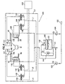
- a control system 100 for the nozzle controllers 40 has pipeline from a compressed air supply 102 connected through a first air decompressing valve 104 to a succeeding stage where the pipeline is branched in two ways; that is, one is routed through a first 5-port pilot switch valve 106 to an air cylinder 108 for the first feed bar 30 while the other is routed through a third 5-port pilot switch valve 110 to the first lubricant nozzle N1.
- the pipeline from the compressed air supply 102 is also connected through a second air decompressing valve 104 to an additional succeeding stage where the pipeline is branched in two ways; that is, one is routed through a second 5-port pilot switch valve 114 to an air cylinder 116 for the second feed bar 32 while the other is routed through a second 5-port pilot switch valve 120 to the second lubricant nozzle N2.
- the pipeline originating from the compressed air supply 102 is connected through a second air-decompressing valve 122 to spray air inlets 130 and 132 of the first and second lubricant nozzle N1 and N2.
- a lubricant vessel 140 hermetically containing lubricant L is provided with a stirrer 142 pneumatically activated by compressed air from the compressed air supply 102 and is supplied with compressed air through a third air decompressing valve 144.
- the lubricant L held in the lubricant vessel 140 is transferred to the first and second lubricant nozzles N1 and N2 via pipeline connected at the bottom of the vessel.
- the first and second 5-port pilot switch valves 106 have their respective electromagnetic valves 150 connected to a control panel 150.
- the first and second feed bars 30 and 32 fetch the workpiece W sequentially at a cycle, for example, of 20 spm out of the workpiece supply 12 and deliver it sequentially to the first to fourth press units 20 to 26.
- the first press unit 20 profiles a core end of a raw material by means of forward extrusion.
- the second press unit 22 also conducts forward extrusion to preliminarily upset the profiled core end.
- the third press unit 24 carries out the forward extrusion to upset and finish the core end.
- compressed air is supplied to the air cylinder 108 of the first nozzle-retaining frame 42 and the air cylinder 116 of the second nozzle-retaining frame 43.
- the air cylinders 108 and 116 respectively raise the first and second nozzle retaining frames 42 and 43, and as depicted in Fig. 4, the first and second lubricant nozzles N1 and N2 are shifted to their respective work position to spray lubricant onto the workpiece W.
- both the first and second lubricant nozzles N1 and N2 alternately spray the lubricant onto the single workpiece W, four times from one of the nozzles and totally eight times from both of the nozzles, for 0.14 seconds each time at an interval time of 0.01 seconds from one spraying to another.
- Spraying lubricant from more than one nozzles is desirably conducted on the basis of serial actions to avoid interference of the sprayed lubricant from one nozzle with the sprayed lubricant from another.
- the gripped workpiece W and the first and second lubricant nozzles N1 and N2, which are all fixed to the first and second feed bars 30 and 32, are naturally in fixed relative positions to one another, and the spraying manner is closely analogous to a condition where the lubricant is sprayed onto a stationary object.
- the workpiece W at the initial stage of the spraying is heated to approximately 200 °C due to forming heat developed during the steps of the profiling, preliminary upsetting, and finishing upsetting that the workpiece W has undergone.
- the lubricant L sprayed is instantaneously vaporized when it reaches the heated workpiece W.
- eight-layered lubricant coat is on the machined surface of the workpiece W, and thereafter, it undergoes backward extrusion in the fourth press unit 26 to advantageously attain the cup forming.
- Ikeuchi & Company, Ltd., Osaka, Japan were used to alternately spray lubricant onto the surface of horizontal carbon steel piece of 80 mm in diameter under the following conditions:
- the nozzles were diagonally and symmetrically opposed to each other 333 mm above the carbon steel piece at an angle of 45 degrees to its horizontal surface, and jetted the lubricant with 0.15 MPa in air pressure and 0.10 MPa in lubricant pressure.
- Table 1 providing measurements of adhesion of lubricant film on the surface of the object, ⁇ denotes lubricant film uniformly adhered over the entire surface of the object, ⁇ means the lubricant film adhered over an area less than 100 % and equal to or over 50 % of the entire surface, and x designates the lubricant film adhered over an area less than 50 % of the entire surface.
- the Table 1 also gives measurements of drying property of the sprayed lubricant where ⁇ was given if the lubricant dried instantaneously, ⁇ if it dried one to two seconds after the spraying, and x if it dried two or more seconds after the spraying.
- the desired lubricant temperature during the spraying ranges from 150 to 250 °C.
- the present invention is applicable to an extrusion procedure at a temperature equal to or below the transformation point of material for cup-shaped products such as a constant velocity universal joint outer race, and shaft-shaped products, as well as to a forming procedure for press products requiring high rigidity.
Landscapes
- Engineering & Computer Science (AREA)
- Mechanical Engineering (AREA)
- Forging (AREA)
Abstract
The invention is directed to provide a forming method and a forming apparatus that are, without extending a processing time compared with the conventional practice, capable of sufficiently lubricating a formed object and forming at safety without the lubricant igniting under pressure. In an extruding apparatus, a workpiece is successively transferred to a series of press stages, a conveying unit successively transferring the workpiece is provided with a nozzle for spraying the workpiece with lubricant, and the workpiece and the nozzle are located in fixed relative positions to each other in spraying the workpiece with the lubricant.
Description
- The present invention relates to a forging method and apparatus of forming a material at a temperature below its transformation point into a cup-shaped product such as a constant velocity universal joint outer race, and a shaft-shaped product.
- Among conventional forging methods for producing cup-shaped or shaft-shaped mechanical parts, a cold forging method is commonly used where a material is formed at a temperature below its transformation point by a die and a punch (e.g., see Patent Document 1 listed below). In this method, the material undergoing the forging must be coated with lubricant film, or otherwise, the forging apparatus is seized. A cylindrical workpiece with an unwrought surface of approximately 75 in Rockwell hardness Scale B turns to have a forged surface of 100 or even higher in Rockwell hardness Scale B after it undergoes the first stage of profiling a core end, the second stage of preliminarily upsetting, and the third stage of further upsetting and immediately before the fourth stage of forming the workpiece into a cup by forging.
- There is no way to forge a workpiece as hard as higher than 100 on Scale B, and an "intervening" process should be conducted between the third and fourth stages, including the steps of low-temperature annealing to drop the hardness, shot blasting to eliminate surface oxide film or oxidized scales and bonderizing to form chemical coating over the surface of the workpiece. Instead of bonderizing, insufflating the workpiece with lubricant may attain lubricating effects.
- Among the aforementioned lubricating methods, the bonderizing is unsatisfactory as it drastically reduces a lubricant film thickness after a single step of forming, and the procedures with successive forming steps at a greater forming rate often bring about disappointing lubricating effects. Moreover, with any means for insufflating with the lubricant, it is hard to uniformly coat the workpiece or the die, and if a greater forming rate causes the lubricant film to be discrete, the formed product may be defective, and this is also undesirable for work environments.
- In order to cope with these problems, oil bath forming has been proposed which is a forging method where a material is soaked in a cavity filled with lubricant in advance (e.g., see Patent Document 2). In the case of the oil bath forging, however, lubricant is prone to be confined in space between the material and the bottom of the cavity during the forging process, depending on the material shape. In such a situation, it is necessary to make an opening as a drain for lubricant at the bottom of the cavity of the die to smoothly drain the confined lubricant into an external tank. However, providing such a drain is insufficient because after forming, the formed product may cling to the punch as it is raised together with the punch in preparation for the next press action, which may result in the formed product being pressed again by the punch.
- In order to address the problem, a drain duct leading to the external tank is made at the bottom of the cavity of the die to let the lubricant out, and additionally, a check valve is attached to the course of the drain duct so that it can open the duct when a pressure of the confined lubricant between the bottom of the cavity and the material reaches a predetermined level while it can close the duct when the pressure goes down below the predetermined level (e.g., see Patent Document 3).
- With the improvement, the lubricant residing in the space between the bottom of the cavity and the material is returned to the external tank via the drain duct by virtue of the opening of the check valve, and after completing the forming, the drain duct is closed, and the formed product in tight contact with the bottom of the cavity would not cling to the raised punch. Therefore, the formed product is left in the cavity.
- Patent Document 1:
- Japanese Laid-Open Patent Publication No. 59-220243
- Patent Document 2:
- Japanese Patent Application No. 62-324515
- Patent Document 3:
- Japanese Laid-Open Patent Publication No. 02-187228
- In the above-mentioned extrusion disclosed in Patent Document 2, the intervening processes are time consuming, and the lubricating effects attained by the bonderizing may be lost due to the final extruding. Thus, it is necessary to re-bonderize the formed product prior to the steps of ioning and coining in the fifth stage of the forging procedures.
- In the extrusion disclosed in Patent Document 3, the adhesion of the liquid lubricant is weak, and it is necessary to repeat the bonderizing again before the ioning and coining steps in the fifth stage.
- Furthermore, when the fourth stage of the extrusion is carried out using the oil bath forging where the material is soaked in the lubricant in the cavity, heat resulted from pressurizing the workpiece causes the lubricant to ignite, which is a trouble that must be overcome from the viewpoint of safety management.
- The present invention is made, allowing for disadvantages of lubricant deterioration and ignition during the conventional extrusion procedures mentioned above, and accordingly, it is an object of the present invention to provide a forming method and a forming apparatus that are, without extending a processing time compared with the conventional practice, capable of sufficiently lubricating a formed object and forming it safely without the lubricant igniting under pressure.
- A first invention is a forging method including a plurality of press steps for a formed product. A workpiece heated due to the machining in an earlier press step(s) undergoes spraying with lubricant more than once prior to a press step of forming the workpiece, the spraying with lubricant is conducted when the lubricant sprayed in a preceding spraying procedure has been dried, and eventually after the lubricant sprayed in the final spraying procedure has been dried, the press step of forming the workpiece is conducted.
- Preferred embodiments of the first invention are characterized as follows:
- The workpiece is a constant-velocity universal joint outer race.
- A temperature of the workpiece ranges from 150 to 250 °C when the workpiece is sprayed with lubricant.
- The lubricant used before a forging procedure is a water-dispersive lubricant containing a solid lubricant agent, a lubricative and dispersive adherent agent, and a wetting and vaporizing accelerating agent, and the lubricant used during the forging procedure is a solid lubricant agent.
- The formed product is cup-shaped.
- The formed product is shaft-shaped.
- A second invention is a forming apparatus having an extruding apparatus in which a workpiece is successively transferred to a series of press stages, a conveying unit successively transferring the workpiece is provided with a nozzle for spraying the workpiece with lubricant, and the workpiece and the nozzle are located in fixed relative positions to each other in spraying the workpiece with the lubricant.
- Preferred embodiments of the second invention are characterized as follows:
- The spraying with lubricant is conducted intermittently.
- There are more than one of the nozzles from which the lubricant is sprayed in different directions, and the nozzles spray the lubricant in a sequential fashion.
- After the lubricant sprayed from one of the nozzles has been dried, the lubricant is sprayed from another of the nozzles.
- The workpiece is a constant-velocity universal joint outer race.
- A temperature of the workpiece during the spraying with lubricant ranges from 150 to 250 °C when the workpiece is sprayed with lubricant.
- The lubricant used before a forging procedure is a water-dispersive lubricant containing a solid lubricant agent, a lubricative and dispersive adherent agent, and a wetting and vaporizing accelerating agent, and the lubricant used during the forging procedure is a solid lubricant agent.
- The formed product is cup-shaped.
- The formed product is shaft-shaped.
- According to the present invention, without extending a processing time compared with the conventional practice, a formed object can be sufficiently lubricated, and the forming is conducted at safety without the lubricant igniting under pressure.
- An exemplary forming apparatus according to the present invention will be detailed in conjunction with the accompanying drawings.
- An
extruding apparatus 10 is, as shown in Fig. 1, comprised of aworkpiece supply 12 and apress 14. Theworkpiece supply 12 is successively loaded with billet or workpiece W and then retains a chain of the workpiece W in predetermined alignment position for a later sequential transfer. - As can be seen in Fig. 1, the
press 14 has first to fourth press units installed serially equidistantly from one to another: thefirst press unit 20 acting as a forward extruder for profiling a core end, thesecond press unit 22 as a preliminary upsetting mechanism, thethird press unit 24 as a finishing upsetting mechanism, and thefourth press unit 26 as a backward extruder for forming raw material in cup. - On opposite sides of each of the first to
fourth press units 20 to 26, a pair of first andsecond feed bars second feed bars grip claws 38 throughgrip controllers 36. The pairs of the eightgrip claws 32 and their respective associatedgrip controllers 30 are opposed to their respective counterpart pairs to pinch the workpiece W in the first tofourth press units 20 to 26. - The first and
second feed bars fourth press units 20 to 26. - The first and
second feed bars retaining frames grip controllers 36 which are dedicated to thethird press unit 24, by means of associatednozzle controllers 40, and thenozzle retaining frames 42 have their respective distal ends provided with first and second lubricant nozzles N1 and N2, respectively. The first and second lubricant nozzles N1 and N2 are binary fluid nozzles that use high-pressure air to spray lubricant. To avoid mutual interference among the first and second lubricant nozzles N1 and N2, the nozzle retainingframes feed bars feed bars nozzle controllers 40 shift the first and second lubricant nozzles N1 and N2 to their respective work positions, namely, the upper dead spots. - As will be recognized in Fig. 4, a
control system 100 for thenozzle controllers 40 has pipeline from acompressed air supply 102 connected through a firstair decompressing valve 104 to a succeeding stage where the pipeline is branched in two ways; that is, one is routed through a first 5-portpilot switch valve 106 to anair cylinder 108 for thefirst feed bar 30 while the other is routed through a third 5-portpilot switch valve 110 to the first lubricant nozzle N1. - The pipeline from the
compressed air supply 102 is also connected through a secondair decompressing valve 104 to an additional succeeding stage where the pipeline is branched in two ways; that is, one is routed through a second 5-portpilot switch valve 114 to anair cylinder 116 for thesecond feed bar 32 while the other is routed through a second 5-portpilot switch valve 120 to the second lubricant nozzle N2. - The pipeline originating from the
compressed air supply 102 is connected through a second air-decompressingvalve 122 to sprayair inlets - A
lubricant vessel 140 hermetically containing lubricant L is provided with astirrer 142 pneumatically activated by compressed air from thecompressed air supply 102 and is supplied with compressed air through a thirdair decompressing valve 144. The lubricant L held in thelubricant vessel 140 is transferred to the first and second lubricant nozzles N1 and N2 via pipeline connected at the bottom of the vessel. The first and second 5-portpilot switch valves 106 have their respectiveelectromagnetic valves 150 connected to acontrol panel 150. - The first and second feed bars 30 and 32 fetch the workpiece W sequentially at a cycle, for example, of 20 spm out of the
workpiece supply 12 and deliver it sequentially to the first tofourth press units 20 to 26. Thefirst press unit 20 profiles a core end of a raw material by means of forward extrusion. Thesecond press unit 22 also conducts forward extrusion to preliminarily upset the profiled core end. Thethird press unit 24 carries out the forward extrusion to upset and finish the core end. - After completing the upsetting by the
third press unit 24, compressed air is supplied to theair cylinder 108 of the first nozzle-retainingframe 42 and theair cylinder 116 of the second nozzle-retainingframe 43. In this way, theair cylinders nozzle retaining frames - Spraying lubricant from more than one nozzles is desirably conducted on the basis of serial actions to avoid interference of the sprayed lubricant from one nozzle with the sprayed lubricant from another.
- During the spraying, the gripped workpiece W and the first and second lubricant nozzles N1 and N2, which are all fixed to the first and second feed bars 30 and 32, are naturally in fixed relative positions to one another, and the spraying manner is closely analogous to a condition where the lubricant is sprayed onto a stationary object.
- The workpiece W at the initial stage of the spraying is heated to approximately 200 °C due to forming heat developed during the steps of the profiling, preliminary upsetting, and finishing upsetting that the workpiece W has undergone. Hence, the lubricant L sprayed is instantaneously vaporized when it reaches the heated workpiece W. As a consequence, eight-layered lubricant coat is on the machined surface of the workpiece W, and thereafter, it undergoes backward extrusion in the
fourth press unit 26 to advantageously attain the cup forming. - Application of waterborne lubricant in use of plastic forming is affected by the temperature of the lubricant, the time required for spraying the lubricant, and a dilution rate of the lubricant. For example, Table 1 below shows the results of a spray test where a pair of nozzles (BIMV4515 available from H. Ikeuchi & Company, Ltd., Osaka, Japan) were used to alternately spray lubricant onto the surface of horizontal carbon steel piece of 80 mm in diameter under the following conditions: The nozzles were diagonally and symmetrically opposed to each other 333 mm above the carbon steel piece at an angle of 45 degrees to its horizontal surface, and jetted the lubricant with 0.15 MPa in air pressure and 0.10 MPa in lubricant pressure.
- In Table 1 providing measurements of adhesion of lubricant film on the surface of the object, ○ denotes lubricant film uniformly adhered over the entire surface of the object, Δ means the lubricant film adhered over an area less than 100 % and equal to or over 50 % of the entire surface, and x designates the lubricant film adhered over an area less than 50 % of the entire surface. The Table 1 also gives measurements of drying property of the sprayed lubricant where ○ was given if the lubricant dried instantaneously, △ if it dried one to two seconds after the spraying, and x if it dried two or more seconds after the spraying.
TABLE 1 Temperature (°C) Time (sec) Number of Times Dilution Rate (times) Adhesion Drying Property 100 0.15 4 10 ○ x 125 0.15 4 10 ○ Δ 150 0.15 4 10 ○ ○ 175 0.15 4 10 ○ ○ 200 0.15 4 10 Δ ○ 200 0.15 4 2.5 ○ ○ 225 0.15 4 2.5 ○ ○ 250 0.15 4 2.5 ○ ○ 275 0.15 4 2.5 Δ ○ 300 0.15 4 2.5 x - - From the above test results, a conclusion can be drawn that the desired lubricant temperature during the spraying ranges from 150 to 250 °C.
- The present invention is applicable to an extrusion procedure at a temperature equal to or below the transformation point of material for cup-shaped products such as a constant velocity universal joint outer race, and shaft-shaped products, as well as to a forming procedure for press products requiring high rigidity.
-
- Fig. 1 is a plan view of an extrusion apparatus according to an embodiment of the present invention;
- Fig. 2 is a cross sectional view taken along the line II-II of Fig. 1;
- Fig. 3 is a diagram illustrating a progressively transformed workpiece in a sequence of stages in press units; and
- Fig. 4 is a circuit diagram illustrating a control system for nozzle controllers.
-
- W
- Workpiece
- L
- Lubricant
- N1
- First Lubricant Nozzle
- N2
- Second Lubricant Nozzle
- 10
- Extruding Apparatus
- 12
- Workpiece Supply
- 14
- Press
- 20
-
First Press Unit 20 - 22
- Second Press Unit
- 24
- Third Press Unit
- 26
- Fourth Press Unit
- 30
- First Feed Bar
- 32
- Second Feed Bar
- 36
- Controllers
- 38
- Grip Claws
- 40
- Nozzle Controller
- 42
- First Nozzle Retaining Frame
- 43
- Second Nozzle Retaining Frame
- 100
- Control System
- 102
- Compressed Air Supply
- 140
- Lubricant Vessel
Claims (15)
- A forging method including a plurality of press steps for a formed product, wherein a workpiece heated due to the machining in an earlier press step(s) undergoes spraying with lubricant more than once prior to a press step of forming the workpiece; the spraying with lubricant is conducted when the lubricant sprayed in a preceding spraying has been dried; and eventually after the lubricant sprayed in the final spraying has been dried, the press step of forming the workpiece is conducted.
- A forging method as defined in Claim 1, wherein the workpiece is a constant-velocity universal joint outer race.
- A forging method as defined in Claim 1, wherein a temperature of the workpiece ranges from 150 to 250 °C when the workpiece is sprayed with lubricant.
- A forging method as defined in Claim 1, wherein the lubricant used before a forging procedure is a water-dispersive lubricant containing a solid lubricant agent, a lubricative and dispersive adherent agent and a wetting and vaporizing accelerating agent, and the lubricant used during the forging procedure is a solid lubricant agent.
- A forging method as defined in Claim 1, wherein the formed product is cup-shaped.
- A forging method as defined in Claim 1, wherein the formed product is shaft-shaped.
- A forging apparatus comprising an extruding apparatus, wherein a workpiece is successively transferred to a series of press stages; a conveying unit for successively transferring the workpiece is provided with a nozzle for spraying the workpiece with lubricant; and the workpiece and the nozzle are located in fixed relative positions to each other in spraying the workpiece with the lubricant.
- A forging apparatus as defined in Claim 7, wherein the spraying with lubricant is conducted intermittently.
- A forging apparatus as defined in Claim 7, wherein there are more than one of the nozzles from which the lubricant is sprayed in different directions, and the nozzles spray the lubricant in a sequential fashion.
- A forging apparatus as defined in Claim 9, wherein after the lubricant sprayed from one of the nozzles has been dried, the lubricant is sprayed from another of the nozzles.
- A forging apparatus as defined in Claim 7, wherein the workpiece is a constant-velocity universal joint outer race.
- A forging apparatus as defined in Claim 7, wherein a temperature of the workpiece ranges from 150 to 250 °C when the workpiece is sprayed with lubricant.
- A forging apparatus as defined in Claim 7, wherein the lubricant used before a forging procedure is a water-dispersive lubricant containing a solid lubricant agent, a lubricative and dispersive adherent agent, and a wetting and vaporizing accelerating agent, and the lubricant used during the forging procedure is a solid lubricant agent.
- A forging apparatus as defined in Claim 7, wherein the formed product is cup-shaped.
- A forging apparatus as defined in Claim 7, wherein the formed product is shaft-shaped.
Applications Claiming Priority (3)
| Application Number | Priority Date | Filing Date | Title |
|---|---|---|---|
| JP2003395682A JP4368669B2 (en) | 2003-11-26 | 2003-11-26 | Forging equipment |
| JP2003395681A JP4611625B2 (en) | 2003-11-26 | 2003-11-26 | Forging method |
| PCT/JP2004/017464 WO2005051565A1 (en) | 2003-11-26 | 2004-11-25 | Method and apparatus for molding by forging |
Publications (2)
| Publication Number | Publication Date |
|---|---|
| EP1693128A1 true EP1693128A1 (en) | 2006-08-23 |
| EP1693128A4 EP1693128A4 (en) | 2009-04-01 |
Family
ID=34635605
Family Applications (1)
| Application Number | Title | Priority Date | Filing Date |
|---|---|---|---|
| EP04819390A Withdrawn EP1693128A4 (en) | 2003-11-26 | 2004-11-25 | Method and apparatus for molding by forging |
Country Status (3)
| Country | Link |
|---|---|
| US (1) | US20070079641A1 (en) |
| EP (1) | EP1693128A4 (en) |
| WO (1) | WO2005051565A1 (en) |
Families Citing this family (1)
| Publication number | Priority date | Publication date | Assignee | Title |
|---|---|---|---|---|
| US20210121906A1 (en) | 2019-10-25 | 2021-04-29 | Lincoln Global, Inc. | Programmable networked variable atomizer (pnva) system |
Family Cites Families (18)
| Publication number | Priority date | Publication date | Assignee | Title |
|---|---|---|---|---|
| US3841126A (en) * | 1972-03-22 | 1974-10-15 | Kobe Steel Ltd | Method of lubricating a work, especially a wire in a warm forging process |
| JPS5345303B2 (en) * | 1972-03-24 | 1978-12-05 | ||
| FR2334427A1 (en) * | 1975-12-09 | 1977-07-08 | Renault | MULTI-NOZZLE BLOCK FOR SPRAYING TOOLING SURFACES |
| JPS5811062A (en) * | 1981-07-13 | 1983-01-21 | Tezuka Kosan Kk | Lubricant applying device for punch |
| JPS61126940A (en) * | 1984-11-21 | 1986-06-14 | Musashi Seimitsu Kogyo Kk | Manufacture of bevel gear by warm forging |
| JPS61129249A (en) * | 1984-11-27 | 1986-06-17 | Musashi Seimitsu Kogyo Kk | Production of bevel gear |
| FR2648062B1 (en) * | 1989-06-07 | 1992-10-30 | Peugeot | IMPROVED AUTOMATIC TRANSFER AND FORGING INSTALLATION OF ANY METAL PARTS |
| JP3120488B2 (en) * | 1991-08-29 | 2000-12-25 | 大同特殊鋼株式会社 | Forging method |
| US5493886A (en) * | 1993-08-23 | 1996-02-27 | Cleveland State University | Elevated temperature metal forming lubrication method |
| US5531085A (en) * | 1994-05-05 | 1996-07-02 | Hayes; John W. | Die lubricant applicator |
| JPH11104780A (en) * | 1997-09-29 | 1999-04-20 | Daiwa Can Co Ltd | Lubricant application device |
| US7043955B2 (en) * | 1997-12-05 | 2006-05-16 | Honda Giken Kogyo Kabushiki Kaisha | Forging die apparatus |
| JP2002059241A (en) * | 2000-08-11 | 2002-02-26 | Toyota Motor Corp | Lubricant application device |
| JP3511015B2 (en) * | 2001-02-22 | 2004-03-29 | 西研グラフィックス株式会社 | Forging press equipment |
| JP4341879B2 (en) * | 2001-06-13 | 2009-10-14 | 株式会社豊田中央研究所 | Pressure molding method and pressure molded member |
| DE60206844T2 (en) * | 2001-06-13 | 2006-07-27 | Kabushiki Kaisha Toyota Chuo Kenkyusho | Method of forming under pressure and element produced thereby |
| US7090729B2 (en) * | 2001-06-28 | 2006-08-15 | Honda Giken Kogyo Kabushiki Kaisha | Outer ring member for constant velocity joint and method of manufacturing the member |
| JP2004314085A (en) * | 2003-04-11 | 2004-11-11 | Honda Motor Co Ltd | Cold-forging method |
-
2004
- 2004-11-25 WO PCT/JP2004/017464 patent/WO2005051565A1/en not_active Ceased
- 2004-11-25 EP EP04819390A patent/EP1693128A4/en not_active Withdrawn
- 2004-11-25 US US10/580,826 patent/US20070079641A1/en not_active Abandoned
Also Published As
| Publication number | Publication date |
|---|---|
| EP1693128A4 (en) | 2009-04-01 |
| WO2005051565A1 (en) | 2005-06-09 |
| US20070079641A1 (en) | 2007-04-12 |
Similar Documents
| Publication | Publication Date | Title |
|---|---|---|
| EP2198984B1 (en) | Piercing plug, method for regenerating piercing plug, and regeneration facility line for piercing plug | |
| US4312210A (en) | Warm forging method for cup-shaped pieces | |
| CN1329141C (en) | Methods for the cold extrusion of metallic elements with dead or through holes and plant for carrying out said methods | |
| CN104245170B (en) | Manufacturing equipment for piercing and rolling plugs | |
| JP7261267B2 (en) | Heat treatment method and heat treatment apparatus | |
| US7090729B2 (en) | Outer ring member for constant velocity joint and method of manufacturing the member | |
| SK165098A3 (en) | Process and device for producing camshafts | |
| CN114260350B (en) | Hot forming method for galvanized sheet | |
| JP4611625B2 (en) | Forging method | |
| WO1994014985A1 (en) | Constrained hardening apparatus and heat treatment apparatus | |
| EP1693128A1 (en) | Method and apparatus for molding by forging | |
| EP0913213B1 (en) | Metalworking method | |
| JP4368669B2 (en) | Forging equipment | |
| KR100602897B1 (en) | Metal member forming method by cold deformation | |
| US12569908B2 (en) | Process for producing blanks of rings | |
| JP2007136510A (en) | Forging method | |
| US860232A (en) | Manufacture of compound pipes and tubes. | |
| CN113000776A (en) | Half axle gear warm forging process | |
| CN121131751B (en) | Modularized efficient vacuum isothermal forming system and method | |
| CN113047089A (en) | Automatic production system and production method for thermal forming of spiral spike | |
| RU2319559C1 (en) | Wire production method | |
| SU804153A1 (en) | Method of monitoring stepped forging dimensions at broaching process | |
| JP2847015B2 (en) | Hot forging equipment | |
| CN109719154A (en) | A kind of processing technology of band steel | |
| CN116833345A (en) | An intelligent hot extrusion forming production line and extrusion forming process |
Legal Events
| Date | Code | Title | Description |
|---|---|---|---|
| PUAI | Public reference made under article 153(3) epc to a published international application that has entered the european phase |
Free format text: ORIGINAL CODE: 0009012 |
|
| 17P | Request for examination filed |
Effective date: 20060626 |
|
| AK | Designated contracting states |
Kind code of ref document: A1 Designated state(s): DE FR GB |
|
| RAP1 | Party data changed (applicant data changed or rights of an application transferred) |
Owner name: HONDA MOTOR CO., LTD. |
|
| DAX | Request for extension of the european patent (deleted) | ||
| RBV | Designated contracting states (corrected) |
Designated state(s): DE FR GB |
|
| A4 | Supplementary search report drawn up and despatched |
Effective date: 20090227 |
|
| STAA | Information on the status of an ep patent application or granted ep patent |
Free format text: STATUS: THE APPLICATION IS DEEMED TO BE WITHDRAWN |
|
| 18D | Application deemed to be withdrawn |
Effective date: 20090528 |