EP1691193A1 - Method for ultrasonic testing of a shadow area of an object in immersion - Google Patents
Method for ultrasonic testing of a shadow area of an object in immersion Download PDFInfo
- Publication number
- EP1691193A1 EP1691193A1 EP06290097A EP06290097A EP1691193A1 EP 1691193 A1 EP1691193 A1 EP 1691193A1 EP 06290097 A EP06290097 A EP 06290097A EP 06290097 A EP06290097 A EP 06290097A EP 1691193 A1 EP1691193 A1 EP 1691193A1
- Authority
- EP
- European Patent Office
- Prior art keywords
- axis
- focused
- workpiece
- angle
- focused beam
- Prior art date
- Legal status (The legal status is an assumption and is not a legal conclusion. Google has not performed a legal analysis and makes no representation as to the accuracy of the status listed.)
- Granted
Links
- 238000000034 method Methods 0.000 title claims abstract description 26
- 238000007654 immersion Methods 0.000 title claims abstract description 7
- 238000012360 testing method Methods 0.000 title claims description 8
- 230000007547 defect Effects 0.000 claims abstract description 27
- 238000002604 ultrasonography Methods 0.000 claims abstract description 15
- 230000007423 decrease Effects 0.000 claims description 8
- RTAQQCXQSZGOHL-UHFFFAOYSA-N Titanium Chemical compound [Ti] RTAQQCXQSZGOHL-UHFFFAOYSA-N 0.000 claims description 5
- 229910052719 titanium Inorganic materials 0.000 claims description 5
- 239000010936 titanium Substances 0.000 claims description 5
- 238000002592 echocardiography Methods 0.000 claims description 4
- 238000006073 displacement reaction Methods 0.000 claims 1
- 230000000873 masking effect Effects 0.000 abstract description 2
- XLYOFNOQVPJJNP-UHFFFAOYSA-N water Substances O XLYOFNOQVPJJNP-UHFFFAOYSA-N 0.000 description 11
- 230000008878 coupling Effects 0.000 description 1
- 238000010168 coupling process Methods 0.000 description 1
- 238000005859 coupling reaction Methods 0.000 description 1
- 238000001514 detection method Methods 0.000 description 1
- 238000013213 extrapolation Methods 0.000 description 1
- 239000007788 liquid Substances 0.000 description 1
- 239000000463 material Substances 0.000 description 1
- 238000005259 measurement Methods 0.000 description 1
- 230000001629 suppression Effects 0.000 description 1
Images


Classifications
-
- G—PHYSICS
- G01—MEASURING; TESTING
- G01N—INVESTIGATING OR ANALYSING MATERIALS BY DETERMINING THEIR CHEMICAL OR PHYSICAL PROPERTIES
- G01N29/00—Investigating or analysing materials by the use of ultrasonic, sonic or infrasonic waves; Visualisation of the interior of objects by transmitting ultrasonic or sonic waves through the object
- G01N29/22—Details, e.g. general constructional or apparatus details
- G01N29/26—Arrangements for orientation or scanning by relative movement of the head and the sensor
- G01N29/265—Arrangements for orientation or scanning by relative movement of the head and the sensor by moving the sensor relative to a stationary material
-
- G—PHYSICS
- G01—MEASURING; TESTING
- G01N—INVESTIGATING OR ANALYSING MATERIALS BY DETERMINING THEIR CHEMICAL OR PHYSICAL PROPERTIES
- G01N29/00—Investigating or analysing materials by the use of ultrasonic, sonic or infrasonic waves; Visualisation of the interior of objects by transmitting ultrasonic or sonic waves through the object
- G01N29/04—Analysing solids
- G01N29/043—Analysing solids in the interior, e.g. by shear waves
-
- G—PHYSICS
- G01—MEASURING; TESTING
- G01N—INVESTIGATING OR ANALYSING MATERIALS BY DETERMINING THEIR CHEMICAL OR PHYSICAL PROPERTIES
- G01N29/00—Investigating or analysing materials by the use of ultrasonic, sonic or infrasonic waves; Visualisation of the interior of objects by transmitting ultrasonic or sonic waves through the object
- G01N29/04—Analysing solids
- G01N29/11—Analysing solids by measuring attenuation of acoustic waves
-
- G—PHYSICS
- G01—MEASURING; TESTING
- G01N—INVESTIGATING OR ANALYSING MATERIALS BY DETERMINING THEIR CHEMICAL OR PHYSICAL PROPERTIES
- G01N29/00—Investigating or analysing materials by the use of ultrasonic, sonic or infrasonic waves; Visualisation of the interior of objects by transmitting ultrasonic or sonic waves through the object
- G01N29/22—Details, e.g. general constructional or apparatus details
- G01N29/221—Arrangements for directing or focusing the acoustical waves
-
- G—PHYSICS
- G01—MEASURING; TESTING
- G01N—INVESTIGATING OR ANALYSING MATERIALS BY DETERMINING THEIR CHEMICAL OR PHYSICAL PROPERTIES
- G01N29/00—Investigating or analysing materials by the use of ultrasonic, sonic or infrasonic waves; Visualisation of the interior of objects by transmitting ultrasonic or sonic waves through the object
- G01N29/22—Details, e.g. general constructional or apparatus details
- G01N29/225—Supports, positioning or alignment in moving situation
-
- G—PHYSICS
- G01—MEASURING; TESTING
- G01N—INVESTIGATING OR ANALYSING MATERIALS BY DETERMINING THEIR CHEMICAL OR PHYSICAL PROPERTIES
- G01N2291/00—Indexing codes associated with group G01N29/00
- G01N2291/01—Indexing codes associated with the measuring variable
- G01N2291/015—Attenuation, scattering
-
- G—PHYSICS
- G01—MEASURING; TESTING
- G01N—INVESTIGATING OR ANALYSING MATERIALS BY DETERMINING THEIR CHEMICAL OR PHYSICAL PROPERTIES
- G01N2291/00—Indexing codes associated with group G01N29/00
- G01N2291/04—Wave modes and trajectories
- G01N2291/044—Internal reflections (echoes), e.g. on walls or defects
-
- G—PHYSICS
- G01—MEASURING; TESTING
- G01N—INVESTIGATING OR ANALYSING MATERIALS BY DETERMINING THEIR CHEMICAL OR PHYSICAL PROPERTIES
- G01N2291/00—Indexing codes associated with group G01N29/00
- G01N2291/10—Number of transducers
- G01N2291/101—Number of transducers one transducer
-
- G—PHYSICS
- G01—MEASURING; TESTING
- G01N—INVESTIGATING OR ANALYSING MATERIALS BY DETERMINING THEIR CHEMICAL OR PHYSICAL PROPERTIES
- G01N2291/00—Indexing codes associated with group G01N29/00
- G01N2291/10—Number of transducers
- G01N2291/106—Number of transducers one or more transducer arrays
Definitions
- the present invention relates to a method of controlling an immersion piece by means of a focused ultrasonic wave beam for the detection of defects in the room such as for example bubbles, inclusions, etc.
- the transducer emits a focused ultrasonic wave beam that is partly reflected on the surface of the part and partly transmitted inside the part, the transmitted ultrasonic waves can meet on their path an internal defect capable of reflecting them.
- the echoes from these reflections are picked up by the transducer and their amplitudes represent the importance of the detected faults.
- ultrasonic testing of a workpiece comprises a relative movement between the workpiece and the transducer or a series of transducers, enabling the workpiece to be scanned by one or more focused ultrasound beams.
- the fault will be detected as an echo, but with a smaller and smaller amplitude when approaching the beam focused on the edge of the room, this amplitude being zero when the focused beam no longer meets the room.
- the part of the room in which the amplitude of the echo produced by the reflection of the beam focused on a defect decreases because of this phenomenon is a zone not controllable by the known methods and is called shadow zone or lateral dead zone of the room.
- the known technique does not make it possible to eliminate this lateral dead zone over the entire depth of the piece and it is therefore necessary to give it as a precaution a maximum value, for example of 12 millimeters, while it can be much lower in reality for example twice as small, which corresponds to a relatively large loss of material.
- the object of the invention is in particular to ultrasonically control an immersed part by eliminating the lateral shadow zones, this control being simple, effective and economical.
- the axis of the emitted focused beam being perpendicular to the surface of the part, characterized in that it consists in using an annular ultrasonic transducer with multi-element elements associated with electronic focusing means and, when the axis of the focused beam is close to an edge of the part and passes into a corresponding shadow zone capable of masking at least part of a defect present in this zone, to incline the axis of the focused beam toward the edge of the part relative to the normal to the the surface of the room, at an angle small enough not to change the amplitude of the wave reflected by the defect and large enough to suppress the shadow zone l ateral on all or almost all of the depth of the room.
- the method according to the invention makes it possible to detect a defect close to an edge of the part and situated in a zone of lateral shadow, in the same way as if this defect were outside the shadow zone.
- the signal reflected by the defect is returned to the transducer in the direction of incidence, so that the amplitude of the echo picked up by the transducer is substantially equal to that which would be reflected by an identical defect present at the same depth but outside the shadow zone and which would be detected by means of a beam emitted by the transducer perpendicular to the surface of the part.
- the entire volume of the part is thus controllable precisely.
- the method consists firstly of measuring, on standard pieces, first values of said angle from which the shadow area is suppressed at different depths in the part, and to select for the control an angle that is at least equal to or slightly greater than the maximum of the first measured values.
- It also consists in measuring, on a standard part, a second value of the angle of inclination, from which the amplitude of the wave reflected by a defect begins to decrease when this angle increases, and to be selected for the controls an angle of inclination of the focused beam axis which is between the maximum of the first measured values and said second value.
- the angle of inclination of the incident focused beam relative to the normal to the surface of the piece is approximately 3 °, for the suppression of the shadow zone in the case of a titanium piece.
- the method also includes preliminarily determining the extent of the shadow area from an edge of the workpiece, thereby controlling a major portion of that workpiece with a focused ultrasound beam oriented perpendicular to the workpiece surface, and to incline this focused beam only when one enters the shadow zone.
- FIG. 1 schematically represents a device 10 for ultrasonically inspecting a part 12 in immersion, comprising a tank 14 filled with water 16 in which are immersed the part 12 to be inspected and an ultrasonic transducer 18 generating an ultrasonic wave beam positioned perpendicular to a surface 22 of the workpiece 12, the transducer 18 being separated from this surface 22 of the workpiece by a height of water called "water column" 24.
- the transducer 18 is an ultrasonic phased array transducer associated with electronic focusing means and connected to control means, such as a microcomputer.
- the emitted ultrasonic waves are partly reflected on the surface 22 of the part and partly transmitted inside thereof, the ultrasonic waves transmitted in the part 12 can meet on their path a defect capable of reflecting them.
- a defect is for example a bubble, inclusion, etc., and is represented in standard pieces by a hole 26, 28, the bottom 30 is flat and located on the side of the surface 22 of the workpiece, the hole opening on the lower surface of the workpiece 12.
- the incident waves on the bottom of the holes or on the defects of the parts are reflected towards the multi-element transducer in their direction of incidence, even when this direction is not perpendicular to the surface of the parts.
- the echoes due to the reflections of the ultrasonic waves on the bottoms of the holes are picked up by the transducer 18 and are recorded and displayed on means 32 for displaying their amplitudes such as an oscilloscope, which are connected to the transducer 18.
- the transducer 18 is moved over the surface 22 of the part parallel thereto to a value of the predetermined water column 24.
- the amplitude of the wave reflected by a defect 26 present in this zone is much weaker than that of an identical defect 28 present at the same depth outside this zone 36. This results in a difficulty in locating and evaluating the importance of the defects present in this zone. 36.
- the method according to the invention makes it possible to accurately control the totality of a part 12 by means of a focused ultrasound wave beam by removing the lateral shadow zones of the part.
- axis 38 of the focused beam when the axis 38 of the focused beam is close to an edge 34 of the part and passes into a corresponding shadow zone 36 may at least partially mask a defect 26 present in this area 36, to tilt axis 38 of the beam focused towards the edge 34 of the workpiece relative to the normal to the surface 22 of the workpiece, of an angle sufficiently small not to modify the amplitude of the wave reflected by the defect 26 and sufficiently large to remove the lateral shadow zone 36 on all or almost all of the depth of the piece 12.
- a standard part 40 comprises a hole 46 with a flat bottom 47 sufficiently distant from the edges 34 of the part to be outside the corresponding lateral shadow zones, and another identical hole 52 with a flat bottom 53 sufficiently close to an edge 34 of the part to be masked by the corresponding shadow area 36, the flat bottoms 47, 53 of the holes 46, 52 being located at a depth p 1 of the surface of the piece 40.
- the shadow zone 36 may be set arbitrarily, for example at 12 mm, or determined by a technique which will be described in detail in the following.
- the transducer 18 is separated from the surface of the workpiece by a water column of a predetermined value and the axis 38 of the focused ultrasound beam is oriented perpendicular to the surface of the workpiece 40 and aligned with the hole 46 of the piece for measuring the maximum amplitude of the echo produced by the reflection of the focused beam on the flat bottom 47 of the hole.
- the means 32 are set to display this amplitude at 80% of the screen height.
- the transducer 18 is then moved in translation over the part 40 along the arrow 58, towards the hole 52 of the part and parallel to the surface thereof, until the focused ultrasound beam 20 is in the vicinity of the axis of the hole 52.
- the method then consists of inclining the axis 38 of the focused beam towards the edge 34 of the workpiece relative to the normal to the surface of the workpiece, by an angle ⁇ i for which the amplitude of the wave reflected on the The flat bottom 53 of the hole becomes maximum, that is to say substantially equal to the amplitude of the wave reflected on the flat bottom 47 of the hole 46 previously measured. For this angle of inclination, the shadow zone has been removed at the depth of the flat bottom 53 of the hole.
- the angle of inclination from which the shadow zone 36 is removed at this depth is determined by tilting progressively the axis 38 of the focused beam towards the edge 34 of the piece and visualizing on the means 32 the variation of the amplitude of the wave reflected on the bottom 53 of the hole.
- angles of inclination ⁇ 1 , ⁇ 2 and ⁇ 3 of the axis 38 of the focused beam from which the dead zone 36 disappears and the amplitude of the waves reflected on the flat bottoms 53, 55, 57 of the holes are thus determined. 52, 54 and 56 is maximum, and these determinations are repeated on other flat-bottomed holes located at increasing depths in the room.
- FIG. 5 is a graph showing the curve C1 of variation of the angle of inclination ⁇ i of the axis 38 of the focused beam relative to the normal to the surface of the part as a function of the depth p i of the flat bottom the hole on which the measurement is made. This curve is constructed by measuring the values of the angle of inclination ⁇ i for the depths p 1 , p 2 and p 3 and for a certain number of additional depths.
- the standard parts are made of titanium and the holes with flat cylindrical bottoms have a diameter of 0.4 mm.
- the angle of inclination increases from ⁇ 1 equal to approximately 2.10 °, corresponding to the depth p 1 of the hole 52 of approximately 15 mm, up to a maximum value equal to about 3.2 °. , corresponding to a hole depth of 31 mm, and then decreases to a value of 1.2 ° corresponding to a hole depth of approximately 140 mm.
- This curve C1 makes it possible to determine the value of the angle of inclination of the axis of the focused beam relative to the normal to the surface of the part, from which the lateral shadow zone is removed on the whole or almost the entire depth of the room. This value is given by the maximum value of the angle of inclination ⁇ i , obtained experimentally on standard parts.
- the method also includes measuring, on a standard part, a value of the angle of inclination of the axis of the focused beam, from which the amplitude of the wave reflected by a hole begins to decrease from its value. maximum when this angle increases.
- This value can be determined using any of the standard pieces that have been used for drawing the curve C1 of FIG.
- this value is about 3.5 ° and is represented in FIG. 5 by the line D1.
- Figures 6 and 7 are schematic sectional views illustrating a technique for determining the extent of a shadow zone corresponding to an edge of a workpiece.
- the transducer 18 is separated from the surface 22 of the part 12 by a water column of a predetermined value and the axis 38 of the focused beam is oriented perpendicular to the surface 22 of the part and aligned with a hole 28 at the bottom. plate formed in the room at a given depth and away from its edges 34. The amplitude of the wave reflected on the bottom of the hole is measured and displayed at 80% of the screen height of the means 32.
- An element 60 of deflection of the focused beam 20 is placed on the surface 22 of the workpiece and is moved towards the axis 38 of the beam focused to deflect a portion of this focused beam outside the pickup area of the transducer 18.
- the deflection element 60 is a prism having at least one reflection face 62 inclined, for example at 45 °, on the surface 22 of the part and on the axis 38 of the focused beam, this face 62 ending in an edge 64 in contact with the surface 22 of the workpiece.
- the prism 60 is moved stepwise along the arrow 66 along an axis that intersects the axis 38 of the focused ultrasound beam, between two extreme positions in which one of the prism 60 is externally tangent to the cross section.
- the beam focused on the surface 22 of the part as shown in Figure 6 where the prism 60 is in the position X 1 , and in the other of which it completely deviates the focused beam 20, as shown in Figure 7 where the prism is in the position X 2 .
- D 1 and d 2 denote the distances between the axis 38 of the focused beam and the edge 64 of the prism, respectively equal to
- the prism 60 is for example positioned by means of shims 68 interposed between the prism 60 and the edge 34 of the part, the shims 68 having very precise dimensions making it possible to fix with very great precision, for example of the order of one micrometer , the position of the edge 64 of the prism 60 relative to the axis 38 of the beam.
- FIG. 8 is a graph showing the curve C2 of variation of the amplitude of the echo produced by the reflection of the beam focused on the bottom of the hole as a function of the position of the edge 64 of the prism with respect to the axis 38 of the focused beam along the X axis. To construct this curve, the values of the echo amplitude for the positions of X 1 and X 2 and for a number of intermediate positions are recorded.
- the amplitude decreases from its maximum value corresponding to the position X 1 to a zero or substantially zero value corresponding to the position X 2 .
- the values of X 1 and more particularly of X 2 can. be difficult to obtain accurately. They can be determined by extrapolation using appropriate means for calculating linear or polynomial regression of the curve obtained experimentally.
- the method may consist of raising the two diametrically opposite positions of the edge 64 of the prism with respect to the axis 38 of the focused beam, for which the edge 64 of the prism is tangent to the effective section of the focused beam 20 at the surface. of the piece, the value of the amplitude of the echo produced by the reflection of the beam focused on the bottom of the hole being substantially maximum in these two positions.
- the prism 60 is moved on the surface 22 of the part along the arrow 66 to the position X 1 , then is disposed on the other side of the focused beam 20, symmetrically with respect to the axis 38, and is moved on the surface 22 of the part in the opposite direction to the arrow 66, to a position X ' 1 , equivalent to X 1 .
Abstract
Description
La présente invention concerne un procédé de contrôle d'une pièce en immersion au moyen d'un faisceau d'ondes ultrasonores focalisé pour la détection de défauts dans la pièce tels que par exemple des bulles, des inclusions, etc.The present invention relates to a method of controlling an immersion piece by means of a focused ultrasonic wave beam for the detection of defects in the room such as for example bubbles, inclusions, etc.
Cette technique est mise en oeuvre dans une cuve remplie d'un liquide de couplage acoustique tel que de l'eau, avec un transducteur ultrasonique qui est immergé dans l'eau et qui est orienté vers la pièce à contrôler perpendiculairement à une surface de celle-ci, le transducteur étant séparé de cette surface de la pièce par une hauteur d'eau appelée « colonne d'eau ».This technique is carried out in a tank filled with an acoustic coupling liquid such as water, with an ultrasonic transducer which is immersed in water and which is oriented towards the test piece perpendicularly to a surface of that here, the transducer being separated from this surface of the room by a height of water called "water column".
Le transducteur émet un faisceau d'ondes ultrasonores focalisé qui sont pour partie réfléchies à la surface de la pièce et pour partie transmises à l'intérieur de la pièce, les ondes ultrasonores transmises pouvant rencontrer sur leur trajectoire un défaut interne capable de les réfléchir. Les échos provenant de ces réflexions sont captés par le transducteur et leurs amplitudes représentent l'importance des défauts détectés.The transducer emits a focused ultrasonic wave beam that is partly reflected on the surface of the part and partly transmitted inside the part, the transmitted ultrasonic waves can meet on their path an internal defect capable of reflecting them. The echoes from these reflections are picked up by the transducer and their amplitudes represent the importance of the detected faults.
En pratique, le contrôle par ultrasons d'une pièce comprend un déplacement relatif entre la pièce et le transducteur ou une série de transducteurs, permettant de réaliser un balayage de la pièce par un ou des faisceaux d'ultrasons focalisé.In practice, ultrasonic testing of a workpiece comprises a relative movement between the workpiece and the transducer or a series of transducers, enabling the workpiece to be scanned by one or more focused ultrasound beams.
Lorsqu'un faisceau d'ultrasons focalisé est approché progressivement d'un bord de la pièce, une partie de plus en plus grande de ce faisceau dépasse du bord de la pièce, de sorte qu'une partie de l'énergie du faisceau focalisé est émise en dehors de la pièce et ne sera pas réfléchie par un défaut de la partie de la pièce couverte par le faisceau focalisé.When a focused ultrasound beam is gradually approaching an edge of the workpiece, a larger and larger portion of this beam protrudes from the edge of the workpiece, so that a portion of the focused beam energy is emitted outside the room and will not be reflected by a defect in the part of the room covered by the focused beam.
En conséquence, le défaut sera détecté sous forme d'un écho, mais avec une amplitude de plus en plus faible quand on approche le faisceau focalisé du bord de la pièce, cette amplitude étant nulle quand le faisceau focalisé ne rencontre plus la pièce.As a result, the fault will be detected as an echo, but with a smaller and smaller amplitude when approaching the beam focused on the edge of the room, this amplitude being zero when the focused beam no longer meets the room.
La partie de la pièce dans laquelle l'amplitude de l'écho produit par la réflexion du faisceau focalisé sur un défaut diminue en raison de ce phénomène est une zone non contrôlable par les procédés connus et est appelée zone d'ombre ou zone morte latérale de la pièce.The part of the room in which the amplitude of the echo produced by the reflection of the beam focused on a defect decreases because of this phenomenon is a zone not controllable by the known methods and is called shadow zone or lateral dead zone of the room.
La technique connue ne permet pas de supprimer cette zone morte latérale sur toute la profondeur de la pièce et on est donc amené à lui donner par précaution une valeur maximale, par exemple de 12 millimètres, alors qu'elle peut être beaucoup plus faible en réalité, par exemple deux fois plus faible, ce qui correspond à une perte de matière relativement importante.The known technique does not make it possible to eliminate this lateral dead zone over the entire depth of the piece and it is therefore necessary to give it as a precaution a maximum value, for example of 12 millimeters, while it can be much lower in reality for example twice as small, which corresponds to a relatively large loss of material.
L'invention a notamment pour but de contrôler par ultrasons une pièce en immersion en supprimant les zones d'ombre latérales, ce contrôle étant simple, efficace et économique.The object of the invention is in particular to ultrasonically control an immersed part by eliminating the lateral shadow zones, this control being simple, effective and economical.
Elle propose à cet effet un procédé de contrôle par ultrasons d'une pièce en immersion au moyen d'un transducteur émettant un faisceau d'ondes ultrasonores focalisé et captant les échos produits par les réflexions du faisceau focalisé sur d'éventuels défauts de cette pièce, l'axe du faisceau focalisé émis étant perpendiculaire à la surface de la pièce, caractérisé en ce qu'il consiste à utiliser un transducteur ultrasonique annulaire multiéléments associé à des moyens de focalisation électronique et, quand l'axe du faisceau focalisé est proche d'un bord de la pièce et passe dans une zone d'ombre correspondante susceptible de masquer au moins en partie un défaut présent dans cette zone, à incliner l'axe du faisceau focalisé vers le bord de la pièce par rapport à la normale à la surface de la pièce, d'un angle suffisamment faible pour ne pas modifier l'amplitude de l'onde réfléchie par le défaut et suffisamment grand pour supprimer la zone d'ombre latérale sur la totalité ou la quasi-totalité de la profondeur de la pièce.To this end, it proposes a method of ultrasonic testing of an immersed part by means of a transducer emitting a focused ultrasound wave beam and capturing the echoes produced by the reflections of the focused beam on possible defects in this part. , the axis of the emitted focused beam being perpendicular to the surface of the part, characterized in that it consists in using an annular ultrasonic transducer with multi-element elements associated with electronic focusing means and, when the axis of the focused beam is close to an edge of the part and passes into a corresponding shadow zone capable of masking at least part of a defect present in this zone, to incline the axis of the focused beam toward the edge of the part relative to the normal to the the surface of the room, at an angle small enough not to change the amplitude of the wave reflected by the defect and large enough to suppress the shadow zone l ateral on all or almost all of the depth of the room.
Le procédé selon l'invention permet de détecter un défaut proche d'un bord de la pièce et situé dans une zone d'ombre latérale, de la même façon que si ce défaut était en dehors de la zone d'ombre. Le signal réfléchi par le défaut est renvoyé vers le transducteur dans la direction d'incidence, de sorte que l'amplitude de l'écho capté par le transducteur est sensiblement égale à celle qui serait réfléchie par un défaut identique présent à la même profondeur mais en dehors de la zone d'ombre et qui serait détecté au moyen d'un faisceau émis par le transducteur perpendiculairement à la surface de la pièce. La totalité du volume de la pièce est ainsi contrôlable de manière précise.The method according to the invention makes it possible to detect a defect close to an edge of the part and situated in a zone of lateral shadow, in the same way as if this defect were outside the shadow zone. The signal reflected by the defect is returned to the transducer in the direction of incidence, so that the amplitude of the echo picked up by the transducer is substantially equal to that which would be reflected by an identical defect present at the same depth but outside the shadow zone and which would be detected by means of a beam emitted by the transducer perpendicular to the surface of the part. The entire volume of the part is thus controllable precisely.
Selon une autre caractéristique de l'invention, le procédé consiste au préalable à mesurer, sur des pièces étalons, des premières valeurs dudit angle à partir desquelles la zone d'ombre est supprimée à différentes profondeurs dans la pièce, et à sélectionner pour le contrôle un angle qui est au moins égal ou légèrement supérieur au maximum des premières valeurs mesurées.According to another characteristic of the invention, the method consists firstly of measuring, on standard pieces, first values of said angle from which the shadow area is suppressed at different depths in the part, and to select for the control an angle that is at least equal to or slightly greater than the maximum of the first measured values.
Il consiste également à mesurer, sur une pièce étalon, une seconde valeur de l'angle d'inclinaison, à partir de laquelle l'amplitude de l'onde réfléchie par un défaut commence à diminuer quand cet angle augmente, et à sélectionner pour le contrôle un angle d'inclinaison de l'axe du faisceau focalisé qui est compris entre le maximum des premières valeurs mesurées et ladite seconde valeur.It also consists in measuring, on a standard part, a second value of the angle of inclination, from which the amplitude of the wave reflected by a defect begins to decrease when this angle increases, and to be selected for the controls an angle of inclination of the focused beam axis which is between the maximum of the first measured values and said second value.
En pratique, l'angle d'inclinaison du faisceau focalisé incident par rapport à la normale à la surface de la pièce est de 3° environ, pour la suppression de la zone d'ombre dans le cas d'une pièce en titane.In practice, the angle of inclination of the incident focused beam relative to the normal to the surface of the piece is approximately 3 °, for the suppression of the shadow zone in the case of a titanium piece.
Le procédé consiste également à déterminer préalablement l'étendue de la zone d'ombre depuis un bord de la pièce, ce qui permet de contrôler une majeure partie de cette pièce avec un faisceau d'ultrasons focalisé orienté perpendiculairement à la surface de la pièce, et de n'incliner ce faisceau focalisé que quand on pénètre dans la zone d'ombre.The method also includes preliminarily determining the extent of the shadow area from an edge of the workpiece, thereby controlling a major portion of that workpiece with a focused ultrasound beam oriented perpendicular to the workpiece surface, and to incline this focused beam only when one enters the shadow zone.
D'autres caractéristiques, détails et avantages de l'invention apparaîtront à la lecture de la description suivante faite à titre d'exemple non limitatif en référence aux dessins annexés dans lesquels :
- la figure 1 est une vue schématique en coupe d'un dispositif de contrôle par ultrasons d'une pièce en immersion ;
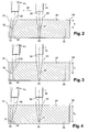
- les figures 2 à 4 sont des vues schématiques en coupe de pièces étalons, illustrant une étape du procédé selon l'invention de contrôle par ultrasons de la pièce ;
- la figure 5 est un graphe représentant la variation de l'angle d'inclinaison du faisceau d'ultrasons focalisé en fonction de la profondeur de trous dans les pièces étalons ;
- les figures 6 et 7 sont des vues schématiques en coupe de la pièce, illustrant une technique de détermination de l'étendue d'une zone d'ombre latérale ;
- la figure 8 est un graphe représentant l'évolution de l'amplitude d'un écho du faisceau focalisé en fonction de la position d'un élément déplacé sur la surface de la pièce par rapport au faisceau.
- Figure 1 is a schematic sectional view of a device for ultrasonic testing of a part in immersion;
- Figures 2 to 4 are schematic sectional views of standard parts, illustrating a step of the method according to the invention ultrasonic testing of the part;
- FIG. 5 is a graph showing the variation of the angle of inclination of the focused ultrasound beam as a function of the depth of holes in the standard pieces;
- Figures 6 and 7 are schematic sectional views of the part, illustrating a technique for determining the extent of a side-shadow area;
- FIG. 8 is a graph showing the evolution of the amplitude of an echo of the focused beam as a function of the position of an element displaced on the surface of the part relative to the beam.
La figure 1 représente schématiquement un dispositif 10 de contrôle par ultrasons d'une pièce 12 en immersion, comprenant une cuve 14 remplie d'eau 16 dans laquelle sont immergés la pièce 12 à contrôler et un transducteur ultrasonique 18 générant un faisceau d'ondes ultrasonores focalisé 20 orienté perpendiculairement à une surface 22 de la pièce 12, le transducteur 18 étant séparé de cette surface 22 de la pièce par une hauteur d'eau appelée « colonne d'eau » 24.FIG. 1 schematically represents a
Le transducteur 18 est un transducteur ultrasonique multiéléments associé à des moyens de focalisation électronique et relié à des moyens de commande, tels qu'un micro-ordinateur.The
Les ondes ultrasonores émises sont pour partie réfléchies à la surface 22 de la pièce et pour partie transmises à l'intérieur de celle-ci, les ondes ultrasonores transmises dans la pièce 12 pouvant rencontrer sur leur trajectoire un défaut capable de les réfléchir. Un défaut est par exemple une bulle, une inclusion, etc, et est représenté dans des pièces étalons par un trou 26, 28 dont le fond 30 est plat et situé du coté de la surface 22 de la pièce, le trou débouchant sur la surface inférieure de la pièce 12.The emitted ultrasonic waves are partly reflected on the
Les ondes incidentes sur les fonds des trous ou sur les défauts des pièces sont réfléchies vers le transducteur multiéléments dans leur direction d'incidence, même lorsque cette direction n'est pas perpendiculaire à la surface des pièces. Les échos dus aux réflexions des ondes ultrasonores sur les fonds 30 des trous sont captés par le transducteur 18 et sont enregistrés et affichés sur des moyens 32 de visualisation de leurs amplitudes tels qu'un oscilloscope, qui sont reliés au transducteur 18.The incident waves on the bottom of the holes or on the defects of the parts are reflected towards the multi-element transducer in their direction of incidence, even when this direction is not perpendicular to the surface of the parts. The echoes due to the reflections of the ultrasonic waves on the bottoms of the holes are picked up by the
Lors d'un contrôle par ultrasons de la pièce 12, le transducteur 18 est déplacé au dessus de la surface 22 de la pièce parallèlement à celle-ci à une valeur de la colonne d'eau 24 prédéterminée.During ultrasonic testing of the
Lorsque le faisceau d'ultrasons focalisé 20 est près d'un bord 34 de la pièce et passe dans une zone d'ombre correspondante, schématiquement délimitée en figure 1 par des lignes 36 en traits pointillés, l'amplitude de l'onde réfléchie par un défaut 26 présent dans cette zone est beaucoup plus faible que celle d'un défaut 28 identique présent à la même profondeur en dehors de cette zone 36. Il en résulte une difficulté à localiser et à évaluer l'importance des défauts présents dans cette zone 36.When the focused
Le procédé selon l'invention permet de contrôler avec précision la totalité d'une pièce 12 au moyen d'un faisceau d'ondes ultrasonores focalisé en supprimant les zones d'ombre latérales de la pièce.The method according to the invention makes it possible to accurately control the totality of a
Il consiste, quand l'axe 38 du faisceau focalisé est proche d'un bord 34 de la pièce et passe dans une zone d'ombre 36 correspondante susceptible de masquer au moins en partie un défaut 26 présent dans cette zone 36, à incliner l'axe 38 du faisceau focalisé vers le bord 34 de la pièce par rapport à la normale à la surface 22 de la pièce, d'un angle suffisamment faible pour ne pas modifier l'amplitude de l'onde réfléchie par le défaut 26 et suffisamment grand pour supprimer la zone d'ombre latérale 36 sur la totalité ou la quasi-totalité de la profondeur de la pièce 12.It consists, when the
Les valeurs de cet angle sont déterminées sur des pièces étalons, comme représenté aux figures 2 à 4.The values of this angle are determined on standard parts, as shown in FIGS. 2 to 4.
En figure 2, une pièce étalon 40 comprend un trou 46 à fond plat 47 suffisamment distant des bords 34 de la pièce pour être en dehors des zones d'ombre latérales correspondantes, et un autre trou 52 identique à fond plat 53 suffisamment proche d'un bord 34 de la pièce pour être masqué par la zone d'ombre 36 correspondante, les fonds plats 47, 53 des trous 46, 52 étant situés à une profondeur p1 de la surface de la pièce 40.In FIG. 2, a
La zone d'ombre 36 peut être fixée arbitrairement, par exemple à 12mm, ou être déterminée par une technique qui sera décrite en détail dans ce qui suit.The
Le transducteur 18 est séparé de la surface de la pièce par une colonne d'eau d'une valeur prédéterminée et l'axe 38 du faisceau d'ultrasons focalisé est orienté perpendiculairement à la surface de la pièce 40 et aligné sur le trou 46 de la pièce pour mesurer l'amplitude maximale de l'écho produit par la réflexion du faisceau focalisé sur le fond plat 47 du trou. En pratique, les moyens 32 sont réglés pour afficher cette amplitude à 80% de la hauteur d'écran.The
Le transducteur 18 est ensuite déplacé en translation au dessus de la pièce 40 suivant la flèche 58, en direction du trou 52 de la pièce et parallèlement à la surface de celle-ci, jusqu'à ce que le faisceau d'ultrasons focalisé 20 soit au voisinage de l'axe du trou 52.The
Le procédé consiste alors à incliner l'axe 38 du faisceau focalisé vers le bord 34 de la pièce par rapport à la normale à la surface de la pièce, d'un angle α i pour lequel l'amplitude de l'onde réfléchie sur le fond plat 53 du trou redevient maximale, c'est-à-dire sensiblement égale à l'amplitude de l'onde réfléchie sur le fond plat 47 du trou 46 précédemment mesurée. Pour cet angle d'inclinaison, la zone d'ombre a été supprimée à la profondeur du fond plat 53 du trou.The method then consists of inclining the
En pratique, l'angle d'inclinaison à partir duquel la zone d'ombre 36 est supprimée à cette profondeur est déterminé en inclinant progressivement l'axe 38 du faisceau focalisé vers le bord 34 de la pièce et en visualisant sur les moyens 32 la variation de l'amplitude de l'onde réfléchie sur le fond 53 du trou.In practice, the angle of inclination from which the
En figures 3 et 4, on procède de la même manière que décrite précédemment sur des pièces étalons 42, 44 dont les fonds plats 49 et 55, et 51 et 57 des trous 48 et 54, et 50 et 56, respectivement, sont à des profondeurs p2 et p3 différentes entre elles et de la profondeur p1.In Figures 3 and 4, one proceeds in the same manner as described above on
On détermine ainsi les angles d'inclinaison α 1, α 2 et α 3 de l'axe 38 du faisceau focalisé à partir desquels la zone morte 36 disparaît et l'amplitude des ondes réfléchies sur les fonds plats 53, 55, 57 des trous 52, 54 et 56 est maximale, et on refait ces déterminations sur d'autres trous à fond plat situés à des profondeurs croissantes dans la pièce.The angles of inclination α 1 , α 2 and α 3 of the
La figure 5 est un graphe représentant la courbe C1 de variation de l'angle d'inclinaison α i de l'axe 38 du faisceau focalisé par rapport à la normale à la surface de la pièce en fonction de la profondeur pi du fond plat du trou sur lequel la mesure est faite. On construit cette courbe par mesure des valeurs de l'angle d'inclinaison α i pour les profondeurs p1, p2 et p3 et pour un certain nombre de profondeurs supplémentaires.FIG. 5 is a graph showing the curve C1 of variation of the angle of inclination α i of the
Dans cet exemple, les pièces étalons sont en titane et les trous à fonds plats cylindriques ont un diamètre de 0,4mm.In this example, the standard parts are made of titanium and the holes with flat cylindrical bottoms have a diameter of 0.4 mm.
On voit en figure 5 que l'angle d'inclinaison augmente depuis α 1 égal à 2,10° environ, correspondant à la profondeur p1 du trou 52 de 15mm environ, jusqu'à une valeur maximale égale à 3,2° environ, correspondant à une profondeur de trou de 31 mm, et décroît ensuite jusqu'à une valeur de 1,2° correspondant à une profondeur de trou de 140mm environ.It can be seen in FIG. 5 that the angle of inclination increases from α 1 equal to approximately 2.10 °, corresponding to the depth p 1 of the
Cette courbe C1 permet de déterminer la valeur de l'angle d'inclinaison de l'axe du faisceau focalisé par rapport à la normale à la surface de la pièce, à partir de laquelle la zone d'ombre latérale est supprimée sur la totalité ou la quasi-totalité de la profondeur de la pièce. Cette valeur est donnée par la valeur maximale de l'angle d'inclinaison α i, obtenue expérimentalement sur des pièces étalons.This curve C1 makes it possible to determine the value of the angle of inclination of the axis of the focused beam relative to the normal to the surface of the part, from which the lateral shadow zone is removed on the whole or almost the entire depth of the room. This value is given by the maximum value of the angle of inclination α i , obtained experimentally on standard parts.
Pour une pièce en titane, il suffit donc d'incliner l'axe du faisceau focalisé à son approche des bords de la pièce, d'un angle au moins égal ou préférentiellement légèrement supérieur à 3,2° pour pouvoir supprimer les zones d'ombre latérales.For a titanium workpiece, it is therefore sufficient to incline the axis of the focused beam when approaching the edges of the workpiece, by an angle at least equal to or preferably slightly greater than 3.2 ° in order to be able to remove the work zones. side shadow.
Le procédé consiste également à mesurer, sur une pièce étalon, une valeur de l'angle d'inclinaison de l'axe du faisceau focalisé, à partir de laquelle l'amplitude de l'onde réfléchie par un trou commence à diminuer depuis sa valeur maximale quand cet angle augmente.The method also includes measuring, on a standard part, a value of the angle of inclination of the axis of the focused beam, from which the amplitude of the wave reflected by a hole begins to decrease from its value. maximum when this angle increases.
Cette valeur peut être déterminée en utilisant l'une quelconque des pièces étalons qui ont servi pour le tracé de la courbe C1 de la figure 5.This value can be determined using any of the standard pieces that have been used for drawing the curve C1 of FIG.
Pour une pièce en titane, cette valeur est de 3,5° environ et est représentée en figure 5 par la droite D1.For a titanium piece, this value is about 3.5 ° and is represented in FIG. 5 by the line D1.
On peut donc, en pratique, incliner l'axe du faisceau d'ultrasons focalisé vers le bord de la pièce par rapport à la normale à la surface de la pièce, d'un angle compris entre la valeur maximale obtenue expérimentalement, qui est de 3,2°, et la valeur au-delà de laquelle l'amplitude de l'onde réfléchie sur un trou décroît, qui est de 3,5°. Cette plage de valeurs permet de supprimer la zone morte latérale sur la totalité de la profondeur de la pièce.It is therefore possible, in practice, to incline the axis of the ultrasound beam focused towards the edge of the workpiece relative to the normal to the surface of the workpiece, by an angle between the maximum value obtained experimentally, which is 3.2 °, and the value beyond which the amplitude of the wave reflected on a hole decreases, which is 3.5 °. This range of values removes the lateral dead zone over the entire depth of the part.
Les figures 6 et 7 sont des vues schématiques en coupe illustrant une technique de détermination de l'étendue d'une zone d'ombre correspondant à un bord d'une pièce.Figures 6 and 7 are schematic sectional views illustrating a technique for determining the extent of a shadow zone corresponding to an edge of a workpiece.
Le transducteur 18 est séparé de la surface 22 de la pièce 12 par une colonne d'eau d'une valeur prédéterminée et l'axe 38 du faisceau focalisé est orienté perpendiculairement à la surface 22 de la pièce et aligné sur un trou 28 à fond plat formé dans la pièce à une profondeur donnée et à distance de ses bords 34. L'amplitude de l'onde réfléchie sur le fond 30 du trou est mesurée et affichée à 80% de la hauteur d'écran des moyens 32.The
Un élément 60 de déviation du faisceau focalisé 20 est posé sur la surface 22 de la pièce et est déplacé en direction de l'axe 38 du faisceau focalisé 20 pour dévier une partie de ce faisceau focalisé en dehors de la zone de captation du transducteur 18.An
Dans l'exemple représenté, l'élément de déviation 60 est un prisme présentant au moins une face de réflexion 62 inclinée, par exemple à 45°, sur la surface 22 de la pièce et sur l'axe 38 du faisceau focalisé, cette face 62 se terminant par un bord 64 en contact avec la surface 22 de la pièce.In the example shown, the
Le prisme 60 est déplacé pas à pas suivant la flèche 66 le long d'un axe qui coupe l'axe 38 du faisceau d'ultrasons focalisé, entre deux positions extrêmes dans l'une desquelles le prisme 60 est extérieurement tangent à la section efficace du faisceau focalisé sur la surface 22 de la pièce, comme représenté en figure 6 où le prisme 60 est dans la position X1, et dans l'autre desquelles il dévie entièrement le faisceau focalisé 20, comme représenté en figure 7 où le prisme est dans la position X2. On définit par d1 et d2 les distances entre l'axe 38 du faisceau focalisé et le bord 64 du prisme, égales à respectivement |X1| et |X2|.The
Le prisme 60 est par exemple positionné au moyen de cales 68 interposées entre le prisme 60 et le bord 34 de la pièce, les cales 68 ayant des dimensions très précises permettant de fixer avec une très grande précision, par exemple de l'ordre du micromètre, la position du bord 64 du prisme 60 par rapport à l'axe 38 du faisceau.The
La figure 8 est un graphe représentant la courbe C2 de variation de l'amplitude de l'écho produit par la réflexion du faisceau focalisé sur le fond 30 du trou en fonction de la position du bord 64 du prisme par rapport à l'axe 38 du faisceau focalisé le long de l'axe X. Pour construire cette courbe, on relève les valeurs de l'amplitude de l'écho pour les positions de X1 et X2 et pour un certain nombre de positions intermédiaires.FIG. 8 is a graph showing the curve C2 of variation of the amplitude of the echo produced by the reflection of the beam focused on the bottom of the hole as a function of the position of the
L'amplitude décroît depuis sa valeur maximale correspondant à la position X1 jusqu'à une valeur nulle ou sensiblement nulle correspondant à la position X2.The amplitude decreases from its maximum value corresponding to the position X 1 to a zero or substantially zero value corresponding to the position X 2 .
La dimension de la zone d'ombre est égale au rayon R de la section efficace du faisceau focalisé 20 à la surface de la pièce qui est défini par l'expression : ![]()
![]()
Dans l'exemple illustré en figure 8, pour une valeur de la colonne d'eau de 40,8mm entre un transducteur Panametrics V322-239 440 de focale F = 8 pouces (203,2mm) et de diamètre d = 1 pouce (25,4mm), et la surface 22 de la pièce, la dimension de la zone d'ombre est égale à : ![]()
![]()
En pratique, les valeurs de X1 et plus particulièrement de X2 peuvent . être difficiles à obtenir avec précision. Elles peuvent être déterminées par extrapolation en utilisant des moyens appropriés de calcul de régression linéaire ou polynomiale de la courbe obtenue expérimentalement.In practice, the values of X 1 and more particularly of X 2 can. be difficult to obtain accurately. They can be determined by extrapolation using appropriate means for calculating linear or polynomial regression of the curve obtained experimentally.
En variante, le procédé peut consister à relever les deux positions du bord 64 du prisme diamétralement opposées par rapport à l'axe 38 du faisceau focalisé, pour lesquelles le bord 64 du prisme est tangent à la section efficace du faisceau focalisé 20 à la surface de la pièce, la valeur de l'amplitude de l'écho produit par la réflexion du faisceau focalisé sur le fond du trou étant sensiblement maximale dans ces deux positions.As a variant, the method may consist of raising the two diametrically opposite positions of the
Pour cela, le prisme 60 est déplacé sur la surface 22 de la pièce suivant la flèche 66 jusqu'à la position X1, puis est disposé de l'autre côte du faisceau focalisé 20, symétriquement par rapport à l'axe 38, et est déplacé sur la surface 22 de la pièce dans le sens opposé à la flèche 66, jusqu'à une position X'1, équivalente à X1.For this, the
La distance entre ces deux positions X1 et X'1 permet de déterminer la dimension de la zone d'ombre qui est égale à : ![]()
![]()
Claims (7)
Applications Claiming Priority (1)
| Application Number | Priority Date | Filing Date | Title |
|---|---|---|---|
| FR0500835A FR2881228B1 (en) | 2005-01-27 | 2005-01-27 | ULTRASONIC CONTROL METHOD FOR IMMERSION PIECE |
Publications (2)
| Publication Number | Publication Date |
|---|---|
| EP1691193A1 true EP1691193A1 (en) | 2006-08-16 |
| EP1691193B1 EP1691193B1 (en) | 2009-03-11 |
Family
ID=35149216
Family Applications (1)
| Application Number | Title | Priority Date | Filing Date |
|---|---|---|---|
| EP06290097A Active EP1691193B1 (en) | 2005-01-27 | 2006-01-16 | Method for ultrasonic testing of a shadow area of an immersed object |
Country Status (5)
| Country | Link |
|---|---|
| US (1) | US7421901B2 (en) |
| EP (1) | EP1691193B1 (en) |
| DE (1) | DE602006005522D1 (en) |
| FR (1) | FR2881228B1 (en) |
| RU (1) | RU2363944C2 (en) |
Families Citing this family (3)
| Publication number | Priority date | Publication date | Assignee | Title |
|---|---|---|---|---|
| RU2491535C1 (en) * | 2011-12-22 | 2013-08-27 | Открытое акционерное общество Акционерная компания по транспорту нефти "Транснефть" | Ultrasound immersion two-element converter |
| CN105319270A (en) * | 2015-10-16 | 2016-02-10 | 西宁特殊钢股份有限公司 | Detection device and method for large-particle occluded foreign substances in steel |
| US10684261B2 (en) * | 2016-04-01 | 2020-06-16 | General Electric Company | Ultrasonic bar and tube end testing with linear axis robot |
Citations (2)
| Publication number | Priority date | Publication date | Assignee | Title |
|---|---|---|---|---|
| JPS6285860A (en) * | 1985-10-11 | 1987-04-20 | Nippon Steel Corp | Ultrasonic flaw detecting method for end part of seam welded tube |
| US5565627A (en) * | 1994-10-11 | 1996-10-15 | Xecutek Corporation | Ultrasonic edge detector and control system |
Family Cites Families (4)
| Publication number | Priority date | Publication date | Assignee | Title |
|---|---|---|---|---|
| DE3789869T2 (en) * | 1987-06-08 | 1994-12-22 | Hitachi Construction Machinery | METHOD FOR MEASURING THE DEPTH OF SURFACE ERROR DEFECTS OF A SOLID MATERIAL USING ULTRASOUND WAVES. |
| US5497662A (en) * | 1993-09-07 | 1996-03-12 | General Electric Company | Method and apparatus for measuring and controlling refracted angle of ultrasonic waves |
| AU2003203256A1 (en) * | 2002-01-17 | 2003-07-30 | Nsk Ltd. | Bearing steel, method for evaluating large-sized inclusions in the steel, and rolling bearing |
| FR2880425B1 (en) * | 2005-01-06 | 2007-02-16 | Snecma Moteurs Sa | DETERMINING THE EXTENT OF A LATERAL SHADOW AREA IN AN ULTRASONIC CONTROL METHOD |
-
2005
- 2005-01-27 FR FR0500835A patent/FR2881228B1/en not_active Expired - Fee Related
-
2006
- 2006-01-16 DE DE602006005522T patent/DE602006005522D1/en active Active
- 2006-01-16 EP EP06290097A patent/EP1691193B1/en active Active
- 2006-01-20 US US11/335,639 patent/US7421901B2/en active Active
- 2006-01-26 RU RU2006102340/28A patent/RU2363944C2/en active
Patent Citations (2)
| Publication number | Priority date | Publication date | Assignee | Title |
|---|---|---|---|---|
| JPS6285860A (en) * | 1985-10-11 | 1987-04-20 | Nippon Steel Corp | Ultrasonic flaw detecting method for end part of seam welded tube |
| US5565627A (en) * | 1994-10-11 | 1996-10-15 | Xecutek Corporation | Ultrasonic edge detector and control system |
Non-Patent Citations (2)
| Title |
|---|
| J. KRAUTKRÄMER, H. KRAUTKRÄMER, ULTRASONIC TESTING OF MATERIALS, 1983, Springer-Verag, Berlin Heidelberg New York, XP002352087 * |
| PATENT ABSTRACTS OF JAPAN vol. 011, no. 291 (P - 618) 19 September 1987 (1987-09-19) * |
Also Published As
| Publication number | Publication date |
|---|---|
| US20060162457A1 (en) | 2006-07-27 |
| US7421901B2 (en) | 2008-09-09 |
| DE602006005522D1 (en) | 2009-04-23 |
| RU2363944C2 (en) | 2009-08-10 |
| FR2881228B1 (en) | 2007-09-28 |
| FR2881228A1 (en) | 2006-07-28 |
| RU2006102340A (en) | 2007-08-20 |
| EP1691193B1 (en) | 2009-03-11 |
Similar Documents
| Publication | Publication Date | Title |
|---|---|---|
| US11353430B2 (en) | Phased array probe and method for testing a spot-weld | |
| EP1516178B1 (en) | Method for ultrasonic control of weld joints | |
| WO2014147344A1 (en) | Device and method for the non-destructive control of tubular products using electroacoustic phased networks, in particular on site | |
| EP3574316B1 (en) | Multielement method and device for testing parts with ultrasound | |
| EP1691193B1 (en) | Method for ultrasonic testing of a shadow area of an immersed object | |
| EP0099816B1 (en) | Method and apparatus for ultrasonic echography | |
| Reverdy et al. | Advantages and complementarity of phased-array technology and total focusing method | |
| EP1705483B1 (en) | Determination of the expanse of a lateral shadow area in a method of ultrasound testing | |
| JP2000146928A (en) | Method for inspecting spot welding | |
| EP0588732B1 (en) | Method of ultrasonic testing of a metal piece | |
| WO2008043888A1 (en) | Device for the ultrasound control of a part | |
| FR2883640A1 (en) | Ultrasonic examination device for SPFDB type blade, has tank filled with water, and transducer emitting beam of ultrasonic waves with specific frequency, where water column between transducer and blade is equal to focal length of transducer | |
| EP3387422A1 (en) | Method for ultrasonic inspection of an object | |
| EP1782058A2 (en) | System for ultrasonic cartography by transmission, using at least one piezoelectric film | |
| WO2001071339A1 (en) | Method for assessing resilience of a welded assembly and corresponding analysis apparatus for measuring surface ultrasonic wave speeds | |
| JP4636967B2 (en) | Ultrasonic flaw detection method | |
| EP3289348B1 (en) | Method for controlling welds by ultrasound | |
| FR3098302A1 (en) | Surface wave imaging device | |
| EP2166306B1 (en) | Device and method for controlling the dimensions of a fuel rod cladding tube of a nuclear fuel control cluster in a nuclear reactor | |
| JP2010151501A (en) | Method of inspecting flaw by ultrasonic waves, and probe unit for ultrasonic flaw detector | |
| CA3108506A1 (en) | Multi-element ultrasound interior line examination device | |
| JPS6138459A (en) | Ultrasonic flaw detection method |
Legal Events
| Date | Code | Title | Description |
|---|---|---|---|
| PUAI | Public reference made under article 153(3) epc to a published international application that has entered the european phase |
Free format text: ORIGINAL CODE: 0009012 |
|
| AK | Designated contracting states |
Kind code of ref document: A1 Designated state(s): AT BE BG CH CY CZ DE DK EE ES FI FR GB GR HU IE IS IT LI LT LU LV MC NL PL PT RO SE SI SK TR |
|
| AX | Request for extension of the european patent |
Extension state: AL BA HR MK YU |
|
| 17P | Request for examination filed |
Effective date: 20060925 |
|
| AKX | Designation fees paid |
Designated state(s): DE FR GB |
|
| GRAP | Despatch of communication of intention to grant a patent |
Free format text: ORIGINAL CODE: EPIDOSNIGR1 |
|
| RTI1 | Title (correction) |
Free format text: METHOD FOR ULTRASONIC TESTING OF A SHADOW AREA OF AN IMMERSED OBJECT |
|
| RIN1 | Information on inventor provided before grant (corrected) |
Inventor name: COULETTE, RICHARD MICHAEL Inventor name: CHATELLIER, JEAN-YVES FRANCOIS ROGER |
|
| GRAS | Grant fee paid |
Free format text: ORIGINAL CODE: EPIDOSNIGR3 |
|
| GRAA | (expected) grant |
Free format text: ORIGINAL CODE: 0009210 |
|
| AK | Designated contracting states |
Kind code of ref document: B1 Designated state(s): DE FR GB |
|
| REG | Reference to a national code |
Ref country code: GB Ref legal event code: FG4D Free format text: NOT ENGLISH |
|
| REF | Corresponds to: |
Ref document number: 602006005522 Country of ref document: DE Date of ref document: 20090423 Kind code of ref document: P |
|
| PLBE | No opposition filed within time limit |
Free format text: ORIGINAL CODE: 0009261 |
|
| STAA | Information on the status of an ep patent application or granted ep patent |
Free format text: STATUS: NO OPPOSITION FILED WITHIN TIME LIMIT |
|
| 26N | No opposition filed |
Effective date: 20091214 |
|
| REG | Reference to a national code |
Ref country code: FR Ref legal event code: PLFP Year of fee payment: 11 |
|
| REG | Reference to a national code |
Ref country code: FR Ref legal event code: PLFP Year of fee payment: 12 |
|
| REG | Reference to a national code |
Ref country code: FR Ref legal event code: PLFP Year of fee payment: 13 |
|
| REG | Reference to a national code |
Ref country code: FR Ref legal event code: CD Owner name: SAFRAN AIRCRAFT ENGINES Effective date: 20170717 |
|
| PGFP | Annual fee paid to national office [announced via postgrant information from national office to epo] |
Ref country code: DE Payment date: 20221220 Year of fee payment: 18 |
|
| PGFP | Annual fee paid to national office [announced via postgrant information from national office to epo] |
Ref country code: GB Payment date: 20231219 Year of fee payment: 19 |
|
| PGFP | Annual fee paid to national office [announced via postgrant information from national office to epo] |
Ref country code: FR Payment date: 20231219 Year of fee payment: 19 |