EP1691003A2 - Light system with a covering slab and a lighting body - Google Patents
Light system with a covering slab and a lighting body Download PDFInfo
- Publication number
- EP1691003A2 EP1691003A2 EP20050028778 EP05028778A EP1691003A2 EP 1691003 A2 EP1691003 A2 EP 1691003A2 EP 20050028778 EP20050028778 EP 20050028778 EP 05028778 A EP05028778 A EP 05028778A EP 1691003 A2 EP1691003 A2 EP 1691003A2
- Authority
- EP
- European Patent Office
- Prior art keywords
- circuit board
- covering plate
- printed circuit
- edge
- lighting system
- Prior art date
- Legal status (The legal status is an assumption and is not a legal conclusion. Google has not performed a legal analysis and makes no representation as to the accuracy of the status listed.)
- Withdrawn
Links
Images


Classifications
-
- G—PHYSICS
- G09—EDUCATION; CRYPTOGRAPHY; DISPLAY; ADVERTISING; SEALS
- G09F—DISPLAYING; ADVERTISING; SIGNS; LABELS OR NAME-PLATES; SEALS
- G09F13/00—Illuminated signs; Luminous advertising
-
- E—FIXED CONSTRUCTIONS
- E04—BUILDING
- E04F—FINISHING WORK ON BUILDINGS, e.g. STAIRS, FLOORS
- E04F13/00—Coverings or linings, e.g. for walls or ceilings
- E04F13/07—Coverings or linings, e.g. for walls or ceilings composed of covering or lining elements; Sub-structures therefor; Fastening means therefor
- E04F13/08—Coverings or linings, e.g. for walls or ceilings composed of covering or lining elements; Sub-structures therefor; Fastening means therefor composed of a plurality of similar covering or lining elements
-
- E—FIXED CONSTRUCTIONS
- E04—BUILDING
- E04F—FINISHING WORK ON BUILDINGS, e.g. STAIRS, FLOORS
- E04F15/00—Flooring
- E04F15/02—Flooring or floor layers composed of a number of similar elements
-
- G—PHYSICS
- G02—OPTICS
- G02B—OPTICAL ELEMENTS, SYSTEMS OR APPARATUS
- G02B6/00—Light guides; Structural details of arrangements comprising light guides and other optical elements, e.g. couplings
- G02B6/0001—Light guides; Structural details of arrangements comprising light guides and other optical elements, e.g. couplings specially adapted for lighting devices or systems
- G02B6/0011—Light guides; Structural details of arrangements comprising light guides and other optical elements, e.g. couplings specially adapted for lighting devices or systems the light guides being planar or of plate-like form
- G02B6/0075—Arrangements of multiple light guides
- G02B6/0078—Side-by-side arrangements, e.g. for large area displays
-
- E—FIXED CONSTRUCTIONS
- E04—BUILDING
- E04F—FINISHING WORK ON BUILDINGS, e.g. STAIRS, FLOORS
- E04F11/00—Stairways, ramps, or like structures; Balustrades; Handrails
- E04F11/02—Stairways; Layouts thereof
- E04F11/104—Treads
- E04F2011/1046—Miscellaneous features of treads not otherwise provided for
- E04F2011/1048—Miscellaneous features of treads not otherwise provided for with lighting means
-
- E—FIXED CONSTRUCTIONS
- E04—BUILDING
- E04F—FINISHING WORK ON BUILDINGS, e.g. STAIRS, FLOORS
- E04F2290/00—Specially adapted covering, lining or flooring elements not otherwise provided for
- E04F2290/02—Specially adapted covering, lining or flooring elements not otherwise provided for for accommodating service installations or utility lines, e.g. heating conduits, electrical lines, lighting devices or service outlets
- E04F2290/026—Specially adapted covering, lining or flooring elements not otherwise provided for for accommodating service installations or utility lines, e.g. heating conduits, electrical lines, lighting devices or service outlets for lighting
-
- F—MECHANICAL ENGINEERING; LIGHTING; HEATING; WEAPONS; BLASTING
- F21—LIGHTING
- F21V—FUNCTIONAL FEATURES OR DETAILS OF LIGHTING DEVICES OR SYSTEMS THEREOF; STRUCTURAL COMBINATIONS OF LIGHTING DEVICES WITH OTHER ARTICLES, NOT OTHERWISE PROVIDED FOR
- F21V33/00—Structural combinations of lighting devices with other articles, not otherwise provided for
- F21V33/006—General building constructions or finishing work for buildings, e.g. roofs, gutters, stairs or floors; Garden equipment; Sunshades or parasols
Definitions
- the invention relates to a lighting system comprising a covering plate with at least one luminous element.
- Fields of application of the invention are in the field of functionalization of wall or floor coverings, preferably tiles or tiles, for the production of surfaces with one or more light sources, in particular of astatic and / or informative character.
- An example of the use of the invention lies in the design of driveways or sidewalks, in the aesthetic design of surfaces in function rooms, entrance areas and / or the aesthetic or informative design of building facades and areas in the living area.
- Light sources with an electrically powered light source such as incandescent lamps, light-emitting diodes / SMD, organic light-emitting diodes (oLEDs), metal halide lamps, fluorescent tubes, laser or gas discharge lamps offer the possibility to convert electrical energy into radiation.
- Boards for occupying walls or floors are mostly industrially manufactured components that can be used for the manufacture, stabilization, protection or aesthetic cladding of structurally-manufactured or natural surfaces. Especially widespread are tiles or tiles. If such covering plates are combined with one or more illuminants, they generally offer the possibility of fixing the light source.
- a disadvantage of the known lighting systems is that the mechanical processing of the floor or wall coverings for their preparation is time-consuming and technically complicated tool or at least a professional knowledge of the wiring must be assumed. It is therefore an object of the present invention to provide a simple and inexpensive lighting system that allows for quick assembly and easy wiring, its use, a kit containing the components of the lighting system, and a simple method of functionalizing surfaces with one or more Lichtkörpem. This object is achieved by the measures described in the claims.
- a covering plate (1) is combined in a simple manner with a luminous element.
- the core of the invention is a printed circuit board (2) which is fixed to the covering plate and which carries at least one luminous element (3).
- the material from which the top plate disclosed in the invention is formed is preferably of natural or synthetic origin, but may also be a combination of both.
- the covering plate advantageously consists of no or at least only slightly electrically conductive substances such as clay, ceramics, glass, wood or stone, for example formed as marble, in addition to the natural availability and price often a simple industrial production and processing of the covering plate enable.
- particularly suitable covering tiles are in particular tiles and tiles. If the tiles or tiles are covered on at least one side with a water-repellent glaze, there is also the advantage of protecting walls or floors from moisture by laying them.
- the covering plate can also be formed from a combination of different natural materials, such. B. artificial stone.
- cover plates which are formed from organic-chemical materials
- the materials may be artificially produced, in particular by chemical modification of natural materials or inorganic and organic raw materials, such as linoleum or PVC. Since such synthetic materials often have advantageous properties such as resistance to oxidation, rot, Weathering influences and chemicals have, for a variety of uses of the invention also covering plates, which are formed from a combination of natural and synthetic materials, such as treated with synthetic lacquer wood.
- the spatial dimensions of the covering plate disclosed in the invention can be adapted to individual requirements, advantageously flat or flat covering plates are used.
- the printed circuit board can be configured in various ways, preferably as a single-layer or multilayer printed circuit board.
- thin printed circuit boards preferably those with a height of less than 3.5 mm, are suitable.
- the circuit board can have a wide variety of technical properties, for example, particularly suitable for the invention of printed circuit boards in the at least one feed for electrical energy or electrical energy with electrical information, in particular in the form of electrical conductors integrated. This also has the advantage that even a simple connection of one or more lighting systems to at least one electrical circuit is made possible.
- the fixation of the circuit board to the covering plate can be done in various ways, adaptable to the material used in each case the covering plate and the conductor plate.
- connections by double-sided adhesive strip material, and / or conclusive connections which are formed by a cured material, for example adhesive, component or building material adhesive, but also other fixations, for example by screwing the printed circuit board or mechanical clamping to the covering plate / between preferred the covering plates are suitable.
- the circuit board can advantageously be fixed below the covering plate, that it projects beyond the edge / seam / edge of the lining plate and / or flush with the edge of the lining plate and / or not flush with the lining plate but already ends below the lining plate.
- the printed circuit board with the protruding surface carries at least one luminous element
- this has the essential Advantage that the luminous element is fixed in a simple manner laterally from the covering plate.
- This also makes a particularly simple assembly possible, in particular if the luminous body is fastened in the region in which there are more than two covering plates in spatial proximity, for example the tile cross with four covering plates or in the joints between at least two covering plates.
- at least one, preferably continuous, recess in the lining plate is formed, which is located above the fixed printed circuit board is particularly favorable.
- the one or more recess (s) can be formed in different ways depending on the need, is advantageous in particular a configuration as a hole in or through the covering plate.
- the recess (4) is provided above the printed circuit board or is inserted into this, preferably such that a direct access to elements of the printed circuit board, in particular light and or electric conductors and / or the described luminous body (s) is formed.
- An advantage of this development of the invention is in particular a simple production and use of covering plates, which have at least one visible light source within the covering plate. If the printed circuit board carries the luminous element in the region of the recess, then a particularly practical and simple fixation of the luminous element is made possible, and thus a preferred production of the lighting system according to the invention.
- At least one luminous element and / or connecting cable for connection to electrical lines are provided on the region of the printed circuit board projecting beyond the edge of the covering plate.
- the luminous body disclosed within the combination of features according to the invention may have a great variety of technical properties and dimensions, particularly luminous bodies which at least in one of their spatial dimensions after fixing on the printed circuit board do not exceed the height of the facing plate, whereby a simple production of planes, the With the light system are made possible.
- the luminous element can be equipped with a wide variety of light sources.
- the luminous body preferably contains at least one light source, which is electrically powered. Even with a simple electrical supply, the luminous element or luminous bodies (eg light-emitting diodes) can be controlled in terms of brightness.
- the lighting system is connected to an electrical bus system or is in communication with this.
- the design of the bus system can be adapted to the different uses.
- the bus system is able to supply the electrical energy for all system components as well as the electrical control signals for the printed circuit boards on the electrical bus lines (at least two-wire system), so that the filament (s) (eg RGB light-emitting diode ) can be controlled via the relevant printed circuit board in addressability, light color and light intensity or are.
- the filament (s) eg RGB light-emitting diode
- Particularly suitable for the invention are in particular 2-wire bus systems.
- the electrical bus system according to the invention has, inter alia, the advantageous property that it allows a particularly simple installation and manageable wiring of the lighting system.
- Particularly suitable in this case is a system with two electrically insulated conductors / cables / conductors extending in the joint region and / or below the lining plate, which carrier supports at least one luminous element and / or an electronic SMD (Surface Mounted Device) via the printed circuit board (s). Assembly or chip is supplied with power and / or electrical / electronic control signals.
- SMD Surface Mounted Device
- the printed circuit board is connected to at least one or more control elements, or / and at least one particular electronic receiver chip.
- the receiver chip can be fixed, inter alia, from outside to the circuit board or is already integrated in the circuit board. However, the receiver chip can also be arranged adjacent to the printed circuit board, for example below the covering plate, or at a spatial distance, for example on / below another printed circuit board or covering plate.
- the control can control monochromatic luminous elements (eg LED) on printed circuit boards via at least one two-wire system in terms of brightness, temporal sequence (eg blinking) and energy.
- the bus system control controls RGB luminaires (eg RGB LED) / circuit board (s) in light-brightness, time sequence, light color and energy via at least one two-wire system, whereby each individual luminaire can be addressed.
- RGB luminaires eg RGB LED
- circuit board s
- the control has the advantageous property that the lighting system can be adapted to a wide variety of applications.
- the control allows the simple implementation of external, preferably electrical, signals for individual control of the lighting system.
- the control element is supplied with electrical energy, can be located below the covering surface or in spatial distance from the covering surface and controlled by remote control (radio, infrared) or galvanic / with electrical conductors.
- the control signals can u.a. an addressability of the printed circuit boards / filament) by individual or group-wise control, and / or a brightness control (eg monochrome or RGB (red, green, blue) or light emitting diodes (LEDs)) and / or a color control / Leuchtmaschine- Control, in particular the color specification / of possible RGB illuminants.
- a brightness control eg monochrome or RGB (red, green, blue) or light emitting diodes (LEDs)
- / or a color control / Leuchtmaschine- Control in particular the color specification / of possible RGB illuminants.
- the at least one luminous element is formed as one or more light-emitting diodes. This has, in comparison to conventional luminaires such as incandescent lamps, the advantage of a particularly long life of the filament and a low power consumption when using the light system according to the invention.
- the height of which exceeds or exceeds the height of the luminous element is the use of an SMD light-emitting diode in combination with one or more light guides, whereby a particularly simple assembly and / or fixing of the light exit height is ensured even with such covering plates and / or joints, which lower or exceed the height of the luminous element.
- the use of SMD LEDs in combination with one or more optical fibers may also be advantageous or necessary as required in other embodiments of the tiles and / or joints
- a particularly simple to implement light system also provides that the luminous element or the light emitting diode and / or optical fiber, together with the stainless steel sleeve planar life with the surface of the covering plate and / or the joint closes.
- the lining plate is designed as a tile or tile and the printed circuit board fixed to the covering plate, that over the edge of the covering plate projecting portion of the circuit board does not exceed the usual width of joints between tiles or tiles.
- This has the advantage according to the invention of a particularly simple handling during installation as well as the simple electrical connection of the lighting system, which includes more than one tile or tile, for example to an electrical circuit.
- the electrical lines of the lighting system in the joints and or below the covering plate (s) between two covering plates out and preferably at least partially integrated in the or the circuit boards, whereby a particularly favorable routing of the lighting system, for example the so-called thin bed process is guaranteed.
- the luminous element can also feed several of the at least partially guided with the circuit boards optical fiber, whereby a multiplication of the outgoing light signals is made possible.
- the covering plate is formed transparent or partially transparent.
- the light from the light source preferably arranged laterally of the covering plate can penetrate directly into the covering plate, in particular when light guides are guided starting from the luminous body below the at least partially transparent covering plate.
- the light can be visible to the viewer as one or more light sources above or in the covering plate, even if the illuminating body itself is hidden for the observer, for example in a joint between two lining plates.
- the luminous element is formed by a plurality of light-emitting diodes. This has the advantage that a wide variety of lighting effects or information can be communicated by the lighting system, in particular when the light-emitting diodes are electrically selectively controlled individually or in bundles via the integrated circuit means in the circuit board.
- the lining plate is provided with a mark / information, which is preferably on a slightly removable from the lining plate material, such as a self-adhesive film, and in particular information on the below the lining plate or to be attached Circuit board, preferably makes the associated lines for electrical power and / or optical fibers mediated.
- a mark / information is preferably on a slightly removable from the lining plate material, such as a self-adhesive film, and in particular information on the below the lining plate or to be attached Circuit board, preferably makes the associated lines for electrical power and / or optical fibers mediated.
- the recess above the circuit board / in the covering plate is provided with a light element that communicates with the circuit board via the light and / or electric conductors.
- the recess may be formed, for example, as a socket enclosing translucent material, wherein in the translucent material, which may consist for example of glass and / or a plastic, optical elements, such as lenses, prisms, mirrors, reflektierende Folle (n) and / or electric filament or amplifier, can be integrated, or these form the translucent material.
- the covering plate is provided with more than one circuit board. This has the advantageous property that at least two different signals can be simultaneously communicated to the lighting system or parts of the lighting system from at least one facing panel or from this into radiation and / or a simple control and / or cabling is made possible even by more complicated lighting systems.
- At least one printed circuit board is provided with at least one adhesive and / or protective layer.
- the layer can be formed, for example, on a preferably sanded (top or bottom) surface of the printed circuit board as a tacky structure, in particular for building / tile adhesive, silicone / plastic adhesive, mortar bed:
- the layer, the circuit board also protect against solvents, in particular water and / or dissolved chemical substances- and / or other external influences, for example when the layer contains silicone or is completely formed from silicone, so that a long life of the circuit board is ensured.
- the protective layer (non-sanded side) can also be covered with a peelable film to allow easy fixing below the covering plate, so that an easy production or assembly of the lighting system / circuit board (s) can be made possible, especially if the film is temporally is removed shortly before the attachment of the circuit board on the preferably unbesandeten surface of the circuit board. If more than one side of the circuit board provided with an adhesive and / or protective layer, also a particularly simple attachment of the lighting system according to the invention, for example in an adhesive or adhesive bed, can be achieved beyond.
- At least one lining plate is provided with at least one level compensation, which corresponds to the height of at least one printed circuit board.
- the level compensation can be used as a material such.
- B. ceramic which is provided on one side with an adhesive layer, which is adhesive ready by peeling off an adhesive film and can be glued to the underside of the covering plate.
- the formations of the material can be arbitrary, suitable are, inter alia, rings, cylinders or cuboids.
- a level compensation which is formed as a spatial, eg milled, recess in the covering plate, in which the circuit board is inserted or is.
- the level compensation formed as a recess in the lining plate for receiving a printed circuit board especially flat surfaces of the recess are advantageous because they are a particularly simple attachment of the circuit board, for example.
- the adhesive surface (foil) of the circuit board and / or adhesive / Allow building material adhesive With the adhesive surface (foil) of the circuit board and / or adhesive / Allow building material adhesive.
- Another embodiment of the invention relates to a lighting system which consists of at least two covering plates, which are interconnected by grout material.
- This lighting system has the advantage that it allows a particularly simple interlocking connection between the at least two covering plates, wherein it may be particularly advantageous to conduct possibly necessary connection cable within the joint material, since this is a particularly simple and defined fastening or shuttering of the connection cable in Grout material allows.
- control part used for light control in which in particular the power supply at 220 V is integrated, in particular up to 512 different wires / joint lines can be controlled, wherein in each case 512 different luminous elements can be controlled via each wire / joint line.
- control parts for lighting control are suitable over which more than 512 different wires / joints lines can be controlled or over each wire / joint line more than 512 different filaments are controllable.
- An advantage of the invention is in particular the technical possibility of interchangeability of the luminous / lighting means (e.g., LED), z.
- a particularly suitable variant of the printed circuit board may include the possibility of interchangeability, in particular when using suitable connecting means, e.g. Jacks.
- cables are firmly soldered to the circuit boards.
- These cables can in the joint or under the lining plates by suitable connections, such as. As soldering, pressing, insulation displacement, spot welding, be electrically connected.
- suitable connections such as. As soldering, pressing, insulation displacement, spot welding, be electrically connected.
- the variant that several circuit boards are electrically connected to each other by fixed cable lengths (ready-made variant). Then even eliminates the above electrical connections
- the electrical control of the circuit board (s) instead takes place directly from one (or possibly more) central box (s), in central box (s) in real-time operation as a common time base.
- the invention is also particularly advantageous if only one luminous element is used / controlled per covering plate.
- the luminous element or bodies can be formed in a wide variety of configurations or be visible, for example by means of a mask, attachment, omission, cut-out or recess, e.g. in the joint material or in the material of the covering plate, etc. in a variety of configurations appear or be visible, e.g. as a star, heart, pictogram, etc.
- the printed circuit board in particular does not terminate at the edge of the tile / facing board, but projects beyond the edge of the tile / facing board, in particular if the luminous dot (s) / filament are carried in the joint area by the printed circuit board, so that a particularly simple implementation and handling of the invention is made possible.
- the cable guide (s) of the connection cable in the region of the joint (s) is of particular advantage.
- kits for the production of the light system according to the invention which contains at least one printed circuit board and / or a luminous element and, as needed, additional elements (power supplies, cables / wires and controls).
- additional elements power supplies, cables / wires and controls.
- Favorable insbeosndere is also included in the kit pre-assembled contiguous area / net / tissue / adhesive on which or are already several covering plates.
- the covering plate and / or the printed circuit board and / or luminous element is / are modified by one or more of the features described above, whereby the corresponding advantages according to the invention can be realized.
- the kit of the invention now allows a special easy installation and use of the new lighting system, in particular if it contains passport-compatible parts and / or a description or instructions.
- the kit can also be designed so that the components, in particular the covering plate and / or printed circuit board, and / or the luminous body are pre-assembled, for example, when the circuit board is already fixed to the covering plate and / or if the connecting means / cable of Luminaire are already attached to the intended contacts.
- a kit in which the covering plate and / or printed circuit board and / or lighting and / or connecting means are coated with a peelable film, whereby the installer of the lighting system with a short handle, the removal of the film, a particularly simple installation of the lighting system is made possible, in particular by an additional layer which adheres sufficiently well on construction adhesives / building materials.
- a sanded / structured additional layer is advantageous in order to ensure good adhesion in the (tiling) adhesive bed.
- a further aspect of the invention relates to a method for laying a lighting system according to the invention, in which a surface, for example a floor / path or a facade / wall, is covered with at least one covering panel, on the underside of which at least one printed circuit board is fixed in such a way, that the printed circuit board projects beyond the edge / seam / edge of the covering plate, and that the printed circuit board is or is connected to at least one luminous element.
- This method according to the invention has the advantage that it enables in the simplest way, the realization of the lighting system according to the invention.
- the lighting system When installing the lighting system can be connected to an electrical circuit as a particularly favorable development at least one luminous element.
- This has the advantage that the lighting elements in the simplest way electrical energy is supplied, which is fed, for example, from an external power source.
- a use of the light system according to the invention can also be advantageous in particular in that at least one luminous element is supplied with electrical energy.
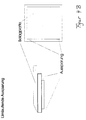
- FIG. 1 shows a covering plate (1) to which a printed circuit board (2) is fixed and which carries a luminous body (3).
- a typical example of the manufacture and installation of the lighting system according to the invention is given below. It is adhered at least one circuit board below a tile (ceramic element / component): On the circuit board is an adhesive surface (for sticking the circuit board to the tile), which is covered with a protective film or a protective paper and by peeling off the film or of the paper exposed is so that the circuit board is ready for adhesive / is. There are also stops on the circuit board that allow precise, precise and quick positioning and sticking. It is a 2-wire bus system used, the two of the board incoming and two outgoing cables in at least one cable / wire ring summarized (eg rolled) and is attached to the top of a tape / Strips.
- the adhesive strip / strip has at least one adhesive side / area which is exposed by peeling off a protective film / paper located thereon and is adhesively fixed on the tile and does not hinder or at least only minimally hinder the further construction process of tile laying.
- the incoming and outgoing cables of the bus system are detached from the tile surface and connected in the joint by a suitable electrical connection, the electrical connection (s) being protected by a moisture and / or moisture barrier alkaline effects (in particular by the Baustoff- or construction adhesive) is protected / is.
- the cables After the cables have been placed in the joints between the tiles (ceramic elements / components), if necessary also with a springy clamping material, joints can easily be grouted.
- the tile joint can be pulled free of the construction adhesive / laying material with a spatula according to the joint width and depth, as long as the adhesive Nerarbeitungsmaterial is not yet cured. This may be necessary, especially for larger areas, in order to lay correspondingly sufficient cable cross-sections.
Landscapes
- Engineering & Computer Science (AREA)
- Architecture (AREA)
- Physics & Mathematics (AREA)
- Civil Engineering (AREA)
- Structural Engineering (AREA)
- General Physics & Mathematics (AREA)
- Optics & Photonics (AREA)
- Theoretical Computer Science (AREA)
- Arrangement Of Elements, Cooling, Sealing, Or The Like Of Lighting Devices (AREA)
- Non-Portable Lighting Devices Or Systems Thereof (AREA)
Abstract
Description
Die Erfindung betrifft ein Lichtsystem aus einer Belagplatte mit mindestens einem Leuchtkörper. Anwendungsgebiete der Erfindung liegen im Bereich der Funktionalisierung von Wand- oder Bodenbelägen, vorzugsweise Kacheln oder Fliesen, zur Herstellung von Flächen mit einer oder mehreren Lichtquellen, insbesondere mit astatischem und/oder informativem Charakter. Ein Beispiel für die Verwendung der Erfindung liegt in der Ausgestaltung von Fahr- oder Gehwegen, in der ästhetischen Ausgestaltung von Flächen in Veranstaltungsräumen, Eingangsbereichen und/oder der ästhetischen oder informativen Ausgestaltung von Gebäudefassaden und Flächen im Wohnbereich.The invention relates to a lighting system comprising a covering plate with at least one luminous element. Fields of application of the invention are in the field of functionalization of wall or floor coverings, preferably tiles or tiles, for the production of surfaces with one or more light sources, in particular of astatic and / or informative character. An example of the use of the invention lies in the design of driveways or sidewalks, in the aesthetic design of surfaces in function rooms, entrance areas and / or the aesthetic or informative design of building facades and areas in the living area.
Leuchtkörper mit einer elektrisch gespeisten Lichtquelle wie etwa Glühlampen, Leuchtdioden / SMD, organische Licht-emittierende Dioden (oLEDs), Metalldampflampen, Leuchtstoffröhren, Laser oder Gasentladungslampen bieten die Möglichkeit, elektrische Energie in Strahlung umzuwandeln.
Platten zur Belegung von Wänden oder Böden sind zumeist industriell gefertigte Bauelemente, die zur Herstellung, Stabilisierung, zum Schutz oder zur ästhetischen Verkleidung von baulich gefertigten oder natürlichen Oberflächen verwendet werden können. Weit verbreitet sind dabei insbesondere Kacheln oder Fliesen. Werden solche Belagplatten mit einer oder mehreren Leuchtkörpern kombiniert, bieten sie ganz allgemein die Möglichkeit, die Lichtquelle zu fixieren.Light sources with an electrically powered light source such as incandescent lamps, light-emitting diodes / SMD, organic light-emitting diodes (oLEDs), metal halide lamps, fluorescent tubes, laser or gas discharge lamps offer the possibility to convert electrical energy into radiation.
Boards for occupying walls or floors are mostly industrially manufactured components that can be used for the manufacture, stabilization, protection or aesthetic cladding of structurally-manufactured or natural surfaces. Especially widespread are tiles or tiles. If such covering plates are combined with one or more illuminants, they generally offer the possibility of fixing the light source.
In der Praxis sind Systeme bekannt, bei denen mit Hilfe mechanischer Bearbeitung räumliche Aussparungen in die Belagplatte eingefügt werden, um dort einen Leuchtkörper zu befestigen oder um eine Verbindung mit einer von der Aussparung räumlich entfernten Lichtquelle zu schaffen. Aus der Druckschrift EP1469141 ist eine Kachel bekannt, die mit einer Aussparung versehen ist, in die ein Leuchtkörper eingebracht wird oder die mit einer solchen verbunden ist.
Aus dem Dokument DE10013496 ist weiterhin ein Prinzip bekannt, mit dessen Hilfe optisch durchlässige Einleger in Fußboden- oder Wandbelägen mit einer räumlich entfernten Lichtquelle verbunden sind.In practice, systems are known in which by means of mechanical processing spatial recesses are inserted into the covering plate in order to fix a luminous body or to create a connection to a spatially remote from the recess light source. From the document EP1469141 a tile is known, which is provided with a recess into which a luminous body is introduced or which is connected to such.
From the document DE10013496 a principle is still known, with the help of optically permeable depositors are connected in floor or wall coverings with a spatially distant light source.
Nachteilig an den bekannten Lichtsystemen ist jedoch, daß die mechanische Bearbeitung der Boden- oder Wandbeläge zu ihrer Herstellung zeitlich und werkzeugtechnisch aufwendig ist oder zumindestens ein fachmännisches Grundwissen für die Verkabelung vorausgesetzt werden muß. Aufgabe der vorliegenden Erfindung ist es daher, ein einfaches und kostengünstiges Lichtsystem anzugeben, das eine schnelle Montage und eine einfache Verkabelung ermöglicht, seine Verwendung, einen Bausatz, der die Bestandteile des Lichtsystems enthält, sowie ein einfaches Verfahren zur Funktionalisierung von Oberflächen mit einer oder mehreren Lichtkörpem. Diese Aufgabe wird durch die in den Ansprüchen beschriebenen Maßnahmen gelöst.A disadvantage of the known lighting systems, however, is that the mechanical processing of the floor or wall coverings for their preparation is time-consuming and technically complicated tool or at least a professional knowledge of the wiring must be assumed. It is therefore an object of the present invention to provide a simple and inexpensive lighting system that allows for quick assembly and easy wiring, its use, a kit containing the components of the lighting system, and a simple method of functionalizing surfaces with one or more Lichtkörpem. This object is achieved by the measures described in the claims.
Nach einem Aspekt der Erfindung wird eine Belagplatte (1) auf einfache Weise mit einem Leuchtkörper kombiniert. Kernstück der Erfindung ist dabei eine Leiterplatte (2), die an der Belagplatte fixiert ist und die wenigstens einen Leuchtkörper (3) trägt.According to one aspect of the invention, a covering plate (1) is combined in a simple manner with a luminous element. The core of the invention is a printed circuit board (2) which is fixed to the covering plate and which carries at least one luminous element (3).
Das Material, aus dem die in der Erfindung offenbarte Belagplatte gebildet ist, ist vorzugsweise natürlichen oder synthetischen Ursprungs, kann aber auch eine Kombination aus beiden darstellen. Die Belagplatte besteht dabei vorteilhafterweise aus nicht oder zumindestens nur geringfügig elektrisch leitenden Substanzen wie etwa Ton, Keramik, Glas, Holz, oder Stein, zum Beispiel als Marmor gebildet, die neben der natürlichen Verfügbarkeit und dem Preis oftmals eine einfache industrielle Fertigung und Verarbeitung der Belagplatte ermöglichen. Für die Erfindung besonders geeignete Belagplatten sind insbesondere Kacheln und Fliesen. Sind die Kacheln oder Fliesen zumindestens auf einer Seite mit einer wasserabweisenden Glasur bedeckt, besteht darüber hinaus der Vorteil, durch ihre Verlegung Wände oder Böden vor Feuchtigkeit zu schützen. Die Belagplatte kann auch aus einer Kombination unterschiedlicher natürlicher Materialien gebildet sein, wie z. B. Kunststein.
Für verschiendenste Anwendungen der Erfindung bieten sich auch Belagplatten an, die aus organisch-chemischen Werkstoffen gebildet sind, wobei die Werkstoffe insbesondere durch chemische Veränderung von Naturstoffen oder aus anorganischen und organischen Rohstoffen künstlich hergestellt sein können, wie beispielsweise Linoleum oder PVC. Da solche synthetischen Materialien oftmals vorteilhafte Eigenschaften wie Beständigkeit gegen Oxidation, Fäulnis, Witterungseinflüsse und Chemikalien aufweisen, bieten sich für unterschiedlichste Verwendungen der Erfindung auch Belagplatten an, die aus einer Kombination natürlicher und synthetischer Materialien gebildet sind, beispielsweise mit Kunstlack behandeltes Holz.
Die räumlichen Abmessungen der in der Erfindung offenbarten Belagplatte können dem individuellen Bedarf angepasst sein, vorteilhafterweise werden dabei flache beziehungsweise ebene Belagplatten verwendet. Neben dem Nutzen eines geringen Materialverbrauchs und einer einfachen Handhabung, kann die Verwendung von flachen oder ebenen Belagplatten darüber hinaus die Fixierung der in der vorliegenden Erfindung offenbarten Leiterplatte an die Belagplatte zumindestens erleichtern. Die Leiterplatte kann verschiedenartig ausgestaltet sein, vorzugsweise als eine ein- oder mehrschichtige Leiterplatte. Für eine einfache Herstellung des erfindungsgemäßen Lichtsystems bieten sich dabei insbesondere dünne Leiterplatten an, vorzugsweise solche mit einer Höhe von weniger als 3,5 mm. Die Leiterplatte kann über unterschiedlichste technische Eigenschaften verfügen, für die Erfindung besonders geeignet sind beispielsweise Leiterplatten in die wenigstens eine Zuführung für Elektroenergie oder Elektroenergie mit elektrischer information insbesondere in Form von elektrischen Leitern, integriert ist. Dies hat zudem den Vorteil, dass auch eine einfache Verbindung von einer oder mehreren Lichtsystemen an wenigstens einen elektrischen Stromkreis ermöglicht wird.The material from which the top plate disclosed in the invention is formed is preferably of natural or synthetic origin, but may also be a combination of both. The covering plate advantageously consists of no or at least only slightly electrically conductive substances such as clay, ceramics, glass, wood or stone, for example formed as marble, in addition to the natural availability and price often a simple industrial production and processing of the covering plate enable. For the invention particularly suitable covering tiles are in particular tiles and tiles. If the tiles or tiles are covered on at least one side with a water-repellent glaze, there is also the advantage of protecting walls or floors from moisture by laying them. The covering plate can also be formed from a combination of different natural materials, such. B. artificial stone.
For verschiendenste applications of the invention also offer cover plates, which are formed from organic-chemical materials, the materials may be artificially produced, in particular by chemical modification of natural materials or inorganic and organic raw materials, such as linoleum or PVC. Since such synthetic materials often have advantageous properties such as resistance to oxidation, rot, Weathering influences and chemicals have, for a variety of uses of the invention also covering plates, which are formed from a combination of natural and synthetic materials, such as treated with synthetic lacquer wood.
The spatial dimensions of the covering plate disclosed in the invention can be adapted to individual requirements, advantageously flat or flat covering plates are used. In addition to the benefits of low material consumption and ease of handling, the use of flat or flat topping plates may also facilitate at least the fixation of the printed circuit board disclosed in the present invention to the topping plate. The printed circuit board can be configured in various ways, preferably as a single-layer or multilayer printed circuit board. For a simple production of the light system according to the invention, in particular thin printed circuit boards, preferably those with a height of less than 3.5 mm, are suitable. The circuit board can have a wide variety of technical properties, for example, particularly suitable for the invention of printed circuit boards in the at least one feed for electrical energy or electrical energy with electrical information, in particular in the form of electrical conductors integrated. This also has the advantage that even a simple connection of one or more lighting systems to at least one electrical circuit is made possible.
Die Fixierung der Leiterplatte an die Belagplatte kann auf verschiedenste Art und Weise erfolgen, anpassbar an das jeweils verwendete Material der Belagplatte und der Leiterpatte. Bevorzugt sind dabei insbesondere Verbindungen durch doppelseitig klebendes Bandmaterial, und/oder schlüssige Verbindungen die von einem ausgehärteten Material, beispielsweise Klebstoff, Komponenten- oder Baustoffkleber ausgebildet sind, aber auch andere Fixierungen, beispielsweise durch eine Verschraubung der Leiterplatte oder mechanische Klemmung an die Belagplatte / zwischen den Belagplatten sind geeignet.
Die Leiterplatte kann vorteilhafterweise unterhalb der Belagplatte fixiert sein, dass sie über den Rand/Naht/Kante der Belagplatte übersteht und/oder bündig mit der Kante der Belagplatte abschließt und/oder nicht bündig mit der Belagplatte abschließt sondern schon unterhalb der Belagplatte endet. Trägt die Leiterplatte mit der überstehenden Fläche wenigstens einen Leuchtkörper, hat dies den wesentlichen Vorteil, dass der Leuchtkörper auf einfache Weise seitlich von der Belagplatte fixiert ist. Dadurch wird auch eine besonders einfache Montage ermöglicht, insbesondere wenn der Leuchtkörper in dem Bereich befestigt ist, bei dem sich mehr als zwei Belagplatten in räumlicher Nähe befinden, zum Beispiel dem Fliesenkreuz bei vier Belagplatten oder in den Fugen zwischen mindestens zwei Belagplatten. Besonders günstig ist daneben auch eine Ausgestaltung, bei der mindestens eine, vorzugsweise durchgängige, Aussparung in der Belagplate gebildet ist, die sich oberhalb der fixierten Leiterplatte befindet. Die eine oder mehrere Aussparung(en) kann dabei je nach Bedarf auf unterschiedliche Weise gebildet sein, vorteilhaft ist dabei insbesondere eine Ausgestaltung als Bohrung in der bzw. durch die Belagplatte. Dabei ist die Aussparung (4) oberhalb der Leiterplatte vorgesehen oder wird in diese eingefügt, vorzugsweise derart, dass ein direkter Zugang zu Elementen der Leiterplatte, insbesondere Licht- und oder Elektroleitern sowie/oder den beschriebenen Leuchtkörper(n), gebildet ist. Vorteilhaft an dieser Weiterbildung der Erfindung ist insbesondere eine einfache Herstellung und Verwendung von Belagplatten, die über wenigstens eine sichtbare Lichtquelle innerhalb der Belagplatte verfügen.
Trägt die Leiterplatte den Leuchtkörper in dem Bereich der Aussparung, so wird in besonders praktische und einfache Fixierung des Leuchtkörpers ermöglicht und somit eine bevorzugte Herstellung des erfindungsgemäßen Lichtsystems. Darüber hinaus kann neben einer Fixierung der Leiterplatte an den Leuchtkörper bzw- Belagplatte auch der Leuchtkörper bereits montagetechnisch vor der Verlegung des Lichtsystems an die Leiterplatte fixiert beziehungsweise mit elektrisch leitenden Elementen der Leiterplatte kontaktiert sein, so dass eine besonders einfache Handhabung der offenbarten Erfindung und Verbindung mit benachbart angeordneten Lichtsystemen ermöglicht wird.
In einer vorteilhaften Weiterbildung der Erfindung sind dazu an dem über den Rand der Belagplatte vorstehende Bereich der Leiterplatte mindestens ein Leuchtkörper und/oder Anschlusskabel zum Anschluß an elektrische Leitungen vorgesehen.
Der innerhalb der erfindungsgemäßen Merkmalskombination offenbarte Leuchtkörper kann über verschiedenste technische Eigenschaften sowie Abmessungen verfügen, besonders geeignet sind insbesondere Leuchtkörper, die zumindestens in einer ihrer räumlichen Dimension nach der Fixierung auf der Leiterplatte nicht die Höhe der Belagplatte überschreiten, wodurch eine einfache Herstellung von Ebenen, die mit dem Lichtsystem ausgestaltet sind, ermöglicht wird. Der Leuchtkörper kann erfindungsgemäß mit unterschiedlichsten Lichtquellen ausgestattet sein, bevorzugt beinhaltet der Leuchtkörper dabei wenigstens eine Lichtquelle, die elektrisch gespeist wird. Auch bei einer einfachen elektrischen Speisung kann der oder die Leuchtkörper (z. B. Leuchtdioden) in der Helligkeit gesteuert werden.
Nach einer vorteilhaften Weiterbildung der Erfindung ist das Lichtsystem an ein elektrisches Bussystem angeschlossen oder steht mit diesem in Verbindung. Die Ausgestaltung des Bussystem kann dabei den unterschiedlichen Verwendungszwecken angepaßt sein. Das Bussystem ist in der Lage auf den elektrischen Bus-Leitungen (mind. Zweileiter System) einerseits die elektrische Energie für alle Systemkomponenten als auch die elektrischen Steuersignale für die Leiterplatten zu liefern, so dass der oder die Leuchtkörper (z. B. RGB - Leuchtdiode) über die betreffende Leiterplatte in Adressierbarkeit, Lichtfarbe und Lichtintensität ansteuerbar ist bzw. sind. Besonders geeignet für die Erfindung sind insbesondere 2-Draht-Bussysteme. Das erfindungsgemäße elektrische Bussystem hat unter anderem die vorteilhafte Eigenschaft, daß es eine besonders einfache Verlegung und überschaubare Verkabelung des Lichtsystems ermöglicht. Geeignet ist dabei insbesondere ein System mit zwei im Fugenbereich und/oder unterhalb der Belagplatte verlaufenden isoliert elektrisch leitenden Adern/Kabeln/Leitern, die über die Leiterplatte(n) als Träger für mindestens einen Leuchtkörper und/oder eine elektronische SMD (Surface Mounted Device)-Baugruppe oder -Chip mit Energie und/oder elektrischen/elektronischen Steuerungssignalen versorgt wird.The fixation of the circuit board to the covering plate can be done in various ways, adaptable to the material used in each case the covering plate and the conductor plate. In particular, connections by double-sided adhesive strip material, and / or conclusive connections which are formed by a cured material, for example adhesive, component or building material adhesive, but also other fixations, for example by screwing the printed circuit board or mechanical clamping to the covering plate / between preferred the covering plates are suitable.
The circuit board can advantageously be fixed below the covering plate, that it projects beyond the edge / seam / edge of the lining plate and / or flush with the edge of the lining plate and / or not flush with the lining plate but already ends below the lining plate. If the printed circuit board with the protruding surface carries at least one luminous element, this has the essential Advantage that the luminous element is fixed in a simple manner laterally from the covering plate. This also makes a particularly simple assembly possible, in particular if the luminous body is fastened in the region in which there are more than two covering plates in spatial proximity, for example the tile cross with four covering plates or in the joints between at least two covering plates. In addition, an embodiment in which at least one, preferably continuous, recess in the lining plate is formed, which is located above the fixed printed circuit board is particularly favorable. The one or more recess (s) can be formed in different ways depending on the need, is advantageous in particular a configuration as a hole in or through the covering plate. In this case, the recess (4) is provided above the printed circuit board or is inserted into this, preferably such that a direct access to elements of the printed circuit board, in particular light and or electric conductors and / or the described luminous body (s) is formed. An advantage of this development of the invention is in particular a simple production and use of covering plates, which have at least one visible light source within the covering plate.
If the printed circuit board carries the luminous element in the region of the recess, then a particularly practical and simple fixation of the luminous element is made possible, and thus a preferred production of the lighting system according to the invention. In addition, in addition to a fixation of the circuit board to the filament or lining plate and the filament already montageetechnically fixed before the installation of the light system to the circuit board or be contacted with electrically conductive elements of the circuit board, so that a particularly simple handling of the disclosed invention and connection with adjacent arranged lighting systems is made possible.
In an advantageous development of the invention, at least one luminous element and / or connecting cable for connection to electrical lines are provided on the region of the printed circuit board projecting beyond the edge of the covering plate.
The luminous body disclosed within the combination of features according to the invention may have a great variety of technical properties and dimensions, particularly luminous bodies which at least in one of their spatial dimensions after fixing on the printed circuit board do not exceed the height of the facing plate, whereby a simple production of planes, the With the light system are made possible. According to the invention, the luminous element can be equipped with a wide variety of light sources. The luminous body preferably contains at least one light source, which is electrically powered. Even with a simple electrical supply, the luminous element or luminous bodies (eg light-emitting diodes) can be controlled in terms of brightness.
According to an advantageous embodiment of the invention, the lighting system is connected to an electrical bus system or is in communication with this. The design of the bus system can be adapted to the different uses. The bus system is able to supply the electrical energy for all system components as well as the electrical control signals for the printed circuit boards on the electrical bus lines (at least two-wire system), so that the filament (s) (eg RGB light-emitting diode ) can be controlled via the relevant printed circuit board in addressability, light color and light intensity or are. Particularly suitable for the invention are in particular 2-wire bus systems. The electrical bus system according to the invention has, inter alia, the advantageous property that it allows a particularly simple installation and manageable wiring of the lighting system. Particularly suitable in this case is a system with two electrically insulated conductors / cables / conductors extending in the joint region and / or below the lining plate, which carrier supports at least one luminous element and / or an electronic SMD (Surface Mounted Device) via the printed circuit board (s). Assembly or chip is supplied with power and / or electrical / electronic control signals.
In einer anderen vorteilhaften Weiterbildung der Erfindung steht die Leiterplatte mit wenigstens einem oder mehreren Steuerelementen, oder/und mindestens einem insbesondere elektronischen Empfänger-Chip, in Verbindung.
Der Empfänger-Chip kann dabei unter anderem von außen an die Leiterplatte fixiert sein oder ist bereits in der Leiterplatte integriert. Der Empfänger-Chip kann aber auch benachbart zur Leiterplatte, z.B. unterhalb der Belagplatte, oder in räumlicher Entfernung, z.B. auf/unter einer anderen Leiterplatte bzw. Belagplatte angeordnet sein.
Das Steuerelement kann einfarbige Leuchtkörper (z. B. LED) auf Leiterplatten über mindestens ein Zweileiter- System in Helligkeit, zeitlicher Abfolge (z. B. Blinken) und Energie steuern.In another advantageous development of the invention, the printed circuit board is connected to at least one or more control elements, or / and at least one particular electronic receiver chip.
The receiver chip can be fixed, inter alia, from outside to the circuit board or is already integrated in the circuit board. However, the receiver chip can also be arranged adjacent to the printed circuit board, for example below the covering plate, or at a spatial distance, for example on / below another printed circuit board or covering plate.
The control can control monochromatic luminous elements (eg LED) on printed circuit boards via at least one two-wire system in terms of brightness, temporal sequence (eg blinking) and energy.
Das Bus-System-Steuerelement steuert über mindestens ein Zweileitersystem RGB - Leuchtkörper (z. B. RGB-LED)/Leiterplatte(n) in Licht-Helligkeit, zeitlicher Abfolge, Licht-Farbe und Energie wobei jeder einzelne Leuchtkörper adressierbar ist.The bus system control controls RGB luminaires (eg RGB LED) / circuit board (s) in light-brightness, time sequence, light color and energy via at least one two-wire system, whereby each individual luminaire can be addressed.
Das Steuerelement hat die vorteilhafte Eigenschaft, daß das Lichtsystem für die verschiedendsten Anwendungsmöglichkeiten anpaßbar ist. Beispielsweise ermöglicht das Steuerelement die einfache Umsetzung äußerer, vorzugsweise elektrischer, Signale zur individuellen Steuerung des Lichtsystems.
Das Steuerelement ist mit elektrischer Energie versorgt, kann sich unterhalb der Belagfläche oder in räumlicher Entfernung zu der Belagfläche befinden und per Fernsteuerung (Funk-, Infrarot-) oder galvanisch / mit elektrischen Leitern angesteuert werden.The control has the advantageous property that the lighting system can be adapted to a wide variety of applications. For example, the control allows the simple implementation of external, preferably electrical, signals for individual control of the lighting system.
The control element is supplied with electrical energy, can be located below the covering surface or in spatial distance from the covering surface and controlled by remote control (radio, infrared) or galvanic / with electrical conductors.
Die Steuerungssignale können dabei u.a. eine Adressierbarkeit der Leiterplatten/Leuchtkörper) durch einzelne oder gruppenweise Ansteuerung ermöglichen, und/oder eine Helligkeitssteuerung (z.B. bei einfarbig oder RGB- (Rot, Grün, Blau)-Leuchtkörpern oder Lichtemittierenden Dioden (LEDs)) und/oder eine Farbsteuerung/Leuchtfarben-Steuerung, insbesondere die Farbvorgabe / von möglichen RGB-Leuchtkörpern.The control signals can u.a. an addressability of the printed circuit boards / filament) by individual or group-wise control, and / or a brightness control (eg monochrome or RGB (red, green, blue) or light emitting diodes (LEDs)) and / or a color control / Leuchtfarben- Control, in particular the color specification / of possible RGB illuminants.
In einer besonders geeigneten Fortbildung der Erfindung ist der wenigstens eine Leuchtkörper als eine oder mehrere Leuchtdioden gebildet. Dies hat, im Vergleich zu herkömmlichen Leuchtkörpern wie beispielsweise Glühlampen, den Vorteil einer besonders langen Haltbarkeit des Leuchtkörpers sowie eines geringen Stromverbrauchs bei der Verwendung des erfindungsgemäßen Lichtsystems.In a particularly suitable development of the invention, the at least one luminous element is formed as one or more light-emitting diodes. This has, in comparison to conventional luminaires such as incandescent lamps, the advantage of a particularly long life of the filament and a low power consumption when using the light system according to the invention.
Günstig ist dabei insbesondere eine Lagerung wenigstens einer Leuchtdiode in einer Edeistahlhülse, die vorzugsweise mit der Leiterplatte in mechanischen und/oder elektrischen Kontakt steht oder mit dieser, insbesondere durch Kabel oder andere elektrische Leiter verbunden ist- Vorteilhaft, insbesondere bei Belagplatten und/oder Fugen, deren Höhe die Höhe des Leuchtkörpers ünter- bzw. überschreitet, ist die Verwendung einer SMD-Leuchtdiode in Kombination mit einem oderen mehreren Lichtleitern., wodurch eine besonders einfache Montage und/oder Festlegung der Lichtaustrittshöhe auch bei solchen Belagplatten und/oder Fugen gewährleistet wird, die die Höhe des Leuchtkörpers ünter- bzw. überschreiten. Allgemein kann die Verwendung von SMD-Leuchtdioden in Kombination mit einem oderen mehreren Lichtleitern je nach Bedarf auch bei anderen Ausgestaltungen der Belagplatten und/oder Fugen von Vorteil oder erforderlich sein
Ein besonders einfach umzusetzendes Lichtsystem sieht darüber hinaus vor, daß der Leuchtkörper bzw. die Leuchtdiode und/oder Lichleiter zusammen mit der Edelstahlhülse planarleben mit der Oberfläche der Belagplatte und/oder der Fuge abschließt.In this case, it is advantageous in particular to mount at least one light-emitting diode in an Edeistahl sleeve, which is preferably in mechanical and / or electrical contact with the printed circuit board or is connected to it, in particular by cables or other electrical conductors. Advantageously, in particular for covering panels and / or joints, the height of which exceeds or exceeds the height of the luminous element is the use of an SMD light-emitting diode in combination with one or more light guides, whereby a particularly simple assembly and / or fixing of the light exit height is ensured even with such covering plates and / or joints, which lower or exceed the height of the luminous element. In general, the use of SMD LEDs in combination with one or more optical fibers may also be advantageous or necessary as required in other embodiments of the tiles and / or joints
A particularly simple to implement light system also provides that the luminous element or the light emitting diode and / or optical fiber, together with the stainless steel sleeve planar life with the surface of the covering plate and / or the joint closes.
Nach einer anderen vorteilhaften Weiterbildung der Erfindung ist die Belagplatte als eine Kachel oder Fliese ausgestaltet und die Leiterplatte derart an die Belagplatte fixiert, dass der über den Rand der Belagplatte überstehende Bereich der Leiterplatte nicht die übliche Breite von Fugen zwischen Kacheln oder Fliesen überschreitet. Dies hat den erfindungsgemäßen Vorteil einer besonders einfachen Handhabung bei der Verlegung sowie der einfachen elektrischen Verbindung des Lichtsystems, das mehr als eine Kachel oder Fliese beinhaltet, beispielsweise an einen elektrischen Stromkreis.
In einer weiteren besonders geeigneten Fortbildung der Erfindung sind die elektrischen Leitungen des Lichtsystems in den Fugen und oder unterhalb der Belagplatte(n) zwischen zwei Belagplatten geführt und vorzugsweise zumindestens teilweise in der oder den Leiterplatten integriert, wodurch eine besonders günstige Verlegung des Lichtsystems, beispielsweise nach dem sogenannten Dünnbettverfahren, gewährleistet ist.
In vorteilhafter Weiterbildung der Erfindung ist die Leiterplatte auf der dem Boden der Belagplatte zugewandten Seite mit mindestens einem Lichtleiter, z.B. Glasfaser, versehen, der vorzugsweise von dem in der erfindungsgemäßen Merkmalskombination vorgesehenen Leuchtkörper gespeist wird, wodurch die einfache Möglichkeit einer gezielten Zuführung von Licht unter die Belagplatte und/oder der lichtleitenden Verbindung zwischen mehr als einer Belagplatte gegeben ist. Darüber hinaus kann der Leuchtkörper auch mehrere der zumindestens teilweise mit den Leiterplatten geführten Lichtleiter speisen, wodurch eine Vervielfachung der ausgehenden Lichtsignale ermöglicht wird.
In einer besonders geeigneten Fortbildung der Erfindung ist die Belagplatte durchsichtig oder teilweise durchsichtig gebildet. Dies hat den erfindungsgemäßen Vorteil, dass das Licht von der vorzugsweise seitlich der Belagplatte angeordneten Lichtquelle direkt in die Belagplatte dringen kann, insbesondere wenn Lichtleiter ausgehend von dem Leuchtkörper unterhalb der zumindestens teilweise durchsichtigen Belagplatte geführt sind. Dadurch kann das Licht für den Betrachter als eine oder mehrere Lichtquellen oberhalb bzw. in der Belagplatte sichtbar werden, auch wenn der Leuchtkörper selbst für den Beobachter verborgen, beispielsweise in einer Fuge zwischen zwei Belagplatten, gelagert ist.
In einer anderen vorteilhaften Weiterbildung der Erfindung ist der Leuchtkörper durch mehrere Leuchtdioden gebildet. Dies hat den Vorteil, dass unterschiedlichste Lichteffekte oder Informationen durch das Lichtsystem vermittelbar sind, insbesondere wenn die Leuchtdioden über die in der Leiterplatte integrierten Anschlußmittel einzeln oder in Bündeln elektrisch gezielt ansteuerbar sind. In einer für verschiedene Anwendungsmöglichkeiten besonders günstigen Fortbildung der Erfindung ist die Belagplatte mit einer Markierung/Information versehen, die sich vorzugsweise auf einem leicht von der Belagplatte entfernbaren Material, beispielsweise einer selbstklebenden Folie, befindet und insbesondere Informationen über die unterhalb der Belagplatte befindlichen oder zu befestigende Leiterplatte, vorzugsweise den damit verbundenen Leitungen für elektrischen Strom und/oder Lichtleitern vermittelbar macht. Dadurch wird beispielsweise für den Verleger des Lichtsystems oder für gegebenenfalls zeitlich nach der Verlegung vorgesehene Änderungen des Lichtsystems, beispielsweise durch Einfügungen von Aussparungen zum Zugriff und/oder zur Freilegung von unterhalb der Belagplatte befindlichen Licht- oder Elektroleitern auf einfache Weise ermöglicht.
In einer besonders geeigneten Weiterbildung der Erfindung ist die Aussparung oberhalb der Leiterplatte / in der Belagplatte mit einem Lichtelement versehen, daß über die Licht- und/oder Elektroleiter mit der Leiterplatte in Verbindung steht. Die Aussparung kann dabei beispielsweise als eine Fassung gebildet sein, die lichtdurchlässiges Material umschließt, wobei in dem lichtdurchlässigen Material, das beispielsweise aus Glas und/oder einem Kunststoff bestehen kann, optische Elemente, z.B. Linsen, Prismen, Spiegel, refelktierende Folle(n) und/oder elektrische Leuchtkörper bzw. verstärker, integriert sein können, bzw. diese das lichtdurchlässige Material bilden. Dieser Aspekt der Erfindung ermöglicht es auf besonders einfache Weise, die Erfindung an die verschiedensten Bedürfnisse und gewünschten optischen Eindrücke anzupassen.According to another advantageous embodiment of the invention, the lining plate is designed as a tile or tile and the printed circuit board fixed to the covering plate, that over the edge of the covering plate projecting portion of the circuit board does not exceed the usual width of joints between tiles or tiles. This has the advantage according to the invention of a particularly simple handling during installation as well as the simple electrical connection of the lighting system, which includes more than one tile or tile, for example to an electrical circuit.
In a further particularly suitable development of the invention, the electrical lines of the lighting system in the joints and or below the covering plate (s) between two covering plates out and preferably at least partially integrated in the or the circuit boards, whereby a particularly favorable routing of the lighting system, for example the so-called thin bed process is guaranteed.
In an advantageous embodiment of the invention, the circuit board on the bottom of the facing plate facing side with at least one optical fiber, eg glass fiber, provided, which is preferably fed by the light feature provided in the feature combination of the invention, whereby the simple possibility of a targeted supply of light under the Plating plate and / or the light-conducting connection between more than one covering plate is given. In addition, the luminous element can also feed several of the at least partially guided with the circuit boards optical fiber, whereby a multiplication of the outgoing light signals is made possible.
In a particularly suitable embodiment of the invention, the covering plate is formed transparent or partially transparent. This has the inventive Advantage that the light from the light source preferably arranged laterally of the covering plate can penetrate directly into the covering plate, in particular when light guides are guided starting from the luminous body below the at least partially transparent covering plate. As a result, the light can be visible to the viewer as one or more light sources above or in the covering plate, even if the illuminating body itself is hidden for the observer, for example in a joint between two lining plates.
In another advantageous embodiment of the invention, the luminous element is formed by a plurality of light-emitting diodes. This has the advantage that a wide variety of lighting effects or information can be communicated by the lighting system, in particular when the light-emitting diodes are electrically selectively controlled individually or in bundles via the integrated circuit means in the circuit board. In a particularly favorable for various applications training of the invention, the lining plate is provided with a mark / information, which is preferably on a slightly removable from the lining plate material, such as a self-adhesive film, and in particular information on the below the lining plate or to be attached Circuit board, preferably makes the associated lines for electrical power and / or optical fibers mediated. This makes it possible, for example, for the publisher of the lighting system or possibly provided for in time after the installation changes the lighting system, for example by inserting recesses for access and / or exposure of located below the covering plate light or electric conductors in a simple manner.
In a particularly suitable embodiment of the invention, the recess above the circuit board / in the covering plate is provided with a light element that communicates with the circuit board via the light and / or electric conductors. The recess may be formed, for example, as a socket enclosing translucent material, wherein in the translucent material, which may consist for example of glass and / or a plastic, optical elements, such as lenses, prisms, mirrors, reflektierende Folle (n) and / or electric filament or amplifier, can be integrated, or these form the translucent material. This aspect of the invention makes it possible in a particularly simple way to adapt the invention to the most diverse needs and desired optical impressions.
In einer weiteren günstigen Fortbildung der Erfindung ist die Belagplatte mit mehr als einer Leiterplatte versehen. Dies hat die vorteilhafte Eigenschaft, daß mindestens zwei unterschiedliche Signale gleichzeitig an das Lichtsystem oder Teilen des Lichtsystems von zu mindestens einer Belagplatte vermittelbar bzw. von diesem in Strahlung umsetzbar sind und/oder eine einfache Ansteuerung und/oder Verkabelung auch von komplizierteren Lichtsystemen ermöglicht wird.In a further favorable development of the invention, the covering plate is provided with more than one circuit board. This has the advantageous property that at least two different signals can be simultaneously communicated to the lighting system or parts of the lighting system from at least one facing panel or from this into radiation and / or a simple control and / or cabling is made possible even by more complicated lighting systems.
In einer anderen vorteilhaften Weiterbildung der Erfindung ist zumindest eine Leiterplatte mit wenigstens einer Haft- und/oder Schutzschicht versehen. Dies hat den Vorteil, daß es beispielsweise eine einfache Fixierung der Leifierplatte an die Belagplatte ermöglicht. Die Schicht kann dabei beispielsweise auf einer vorzugsweise besandeten (Ober- bzw. Unter-)FlächelSeite der-Leiterplatte als eine klebbare Struktur, insbesondere für Bau-/Fliesenkleber, Silikon-/Kunststoffkleber, Mörtelbett gebildet sein: Darüber hinaus kann die Schicht die Leiterplatte auch gegen Lösungsmittel, insbesondere Wasser und/oder gelöste chemische Substanzen- und/oder andere äußere Einflüsse schützen, beispielsweise wenn die Schicht Silikon enthält oder vollständig aus Silikon gebildet ist, so daß eine lange Lebensdauer der Leiterplatte gewährleistet wird. Vorteilhafterweise kann dabei die Schutzschicht (unbesandete Seite) auch mit einer abziehbaren Folie bedeckt sein, um ein einfaches Fixieren unterhalb der Belagplatte zu ermöglichen, so dass eine einfache Herstellung oder Montage des Lichtsystems/Leiterplatte(n) ermöglicht werden kann, insbesondere wenn die Folie zeitlich kurz vor der Befestigung der Leiterplatte an der vorzugsweise unbesandeten Fläche der Leiterplatte entfernt wird. Ist mehr als eine Seite der Leiterplatte mit einer Haft- und/oder Schutzschicht versehen, kann darüber hinaus auch eine besonders einfache Befestigung des erfindungsgemäßen Lichtsystems, beispielsweise in einem Haft- oder Klebebett, erzielt werden.In another advantageous development of the invention, at least one printed circuit board is provided with at least one adhesive and / or protective layer. This has the advantage that it allows, for example, a simple fixation of the Leifier plate to the covering plate. The layer can be formed, for example, on a preferably sanded (top or bottom) surface of the printed circuit board as a tacky structure, in particular for building / tile adhesive, silicone / plastic adhesive, mortar bed: In addition, the layer, the circuit board also protect against solvents, in particular water and / or dissolved chemical substances- and / or other external influences, for example when the layer contains silicone or is completely formed from silicone, so that a long life of the circuit board is ensured. Advantageously, the protective layer (non-sanded side) can also be covered with a peelable film to allow easy fixing below the covering plate, so that an easy production or assembly of the lighting system / circuit board (s) can be made possible, especially if the film is temporally is removed shortly before the attachment of the circuit board on the preferably unbesandeten surface of the circuit board. If more than one side of the circuit board provided with an adhesive and / or protective layer, also a particularly simple attachment of the lighting system according to the invention, for example in an adhesive or adhesive bed, can be achieved beyond.
In einer anderen günstigen Fortbildung ist wenigstens eine Belagplatte mit mindestens einem Niveauausgleich versehen, der der Höhe wenigstens einer Leiterplatte entspricht. Der Niveauausgleich kann dabei als Werkstoff wie z. B. Keramik gebildet sein, der einseitig mit einer Klebeschicht versehen ist, die durch abziehen einer Klebefolie klebebereit ist und auf die Unterseite der Belagplatte geklebt werden kann. Die Ausformungen des Werkstoffs können dabei beliebig sein, geeignet sind u.a. Ringe, Zylinder oder Quader. Möglich ist auch ein Niveauausgleich, der als eine räumliche, z.B. gefräste, Aussparung in der Belagplatte gebildet ist, in die die Leiterplatte eingelassen wird bzw. ist. Ist der Niveauausgleich als Aussparung in der Belagplatte zur Aufnahme einer Leiterplatte gebildet, sind insbesondere auch ebene Flächen der Aussparung von Vorteil, da sie eine besonders einfache Befestigung der Leiterplatte, bspw. mit der klebbaren Fläche (Folie) der Leiterplatte und/oder mit Kleber / Baustoffkleber ermöglichen.In another favorable development at least one lining plate is provided with at least one level compensation, which corresponds to the height of at least one printed circuit board. The level compensation can be used as a material such. B. ceramic, which is provided on one side with an adhesive layer, which is adhesive ready by peeling off an adhesive film and can be glued to the underside of the covering plate. The formations of the material can be arbitrary, suitable are, inter alia, rings, cylinders or cuboids. Also possible is a level compensation, which is formed as a spatial, eg milled, recess in the covering plate, in which the circuit board is inserted or is. If the level compensation formed as a recess in the lining plate for receiving a printed circuit board, especially flat surfaces of the recess are advantageous because they are a particularly simple attachment of the circuit board, for example. With the adhesive surface (foil) of the circuit board and / or adhesive / Allow building material adhesive.
Eine andere Ausgestaltung der Erfindung betrifft ein Lichtsystem das aus mindestens zwei Belagplatten besteht, die durch Fugenmaterial miteinander verbunden sind. Dieses Lichtsystem hat den Vorteil, daß es eine besonders einfache schlüssige Verbindung zwischen den mindestens zwei Belagplatten ermöglicht, wobei es insbesondere vorteilhaft sein kann, evt. nötige Anschlußkabel innerhalb des Fugenmaterials zu führen, da dies eine besonders einfache und definierte Befestigung oder Verschalung der Anschlußkabel im Fugenmaterial ermöglicht.Another embodiment of the invention relates to a lighting system which consists of at least two covering plates, which are interconnected by grout material. This lighting system has the advantage that it allows a particularly simple interlocking connection between the at least two covering plates, wherein it may be particularly advantageous to conduct possibly necessary connection cable within the joint material, since this is a particularly simple and defined fastening or shuttering of the connection cable in Grout material allows.
Typisch sind beispielsweise folgende drei Ausführungsformen der Erfindung:
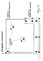
- a) Über einen Lichtdimmer, der als per Hand bedienbare Impulsbreitensteuerung/Lichtsteuerung gebildet ist, steht die Leiterplatte mit einer elektrischen Spannungsversorgung in Verbindung, so dass der Leuchtkörper (z.B. LED) in einer Farbe mit verschiedenen Helligkeiten leuchten kann.
- b) Über einen Lichtdimmer, der als per Hand bedienbare Farbsteuerung/Lichtsteuerung gebildet ist, steht die Leiterplatte mit einer elektrischen Spannungsversorgung in Verbindung, so dass der (z.B. RGB-) Leuchtkörper prinzipiell in allen Farben und Helligkeiten steuerbar/einstellbar ist.
- c) Über eine Lichtsteuerung steht die Leiterplatte mit einem PC (Personal Computer) oder einem Laptop bzw. Notebook in Verbindung, so dass der (z.B, RGB-) Leuchtkörper, ggf. über ein Lichtsteuerungsprogramm, in allen Farben, allen Helligkeiten und adressierbar steuerbar/einstellbar ist, bspw. ein (Licht-) Filmablauf oder Lichtsequenzen regelbar sind.
- a) About a light dimmer, which is formed as a manually operated pulse width control / light control, the circuit board is connected to an electrical power supply, so that the lamp (eg LED) in a color with different brightnesses can shine.
- b) About a light dimmer, which is formed as a manually operated color control / light control, the circuit board is connected to an electrical power supply, so that the (eg RGB) luminous element in principle, in all colors and brightnesses controllable / adjustable.
- c) A light control, the circuit board is connected to a PC (personal computer) or a laptop or notebook so that the (eg, RGB) luminous body, possibly via a lighting control program, in all colors, all brightnesses and addressable controllable / is adjustable, for example, a (light) film sequence or light sequences are adjustable.
Über das dabei verwendete Steuerungsteil zur Lichtsteuerung, in dem insbesondere auch die Stromversorgung bei 220 V integriert ist, lassen sich insbesondere bis zu 512 verschiedene Drähte/Fugenlinien ansteuern, wobei über jeden Draht/Fugenlinie wiederum 512 unterschiedliche Leuchtkörper steuerbar sind.
Aber auch andere Steuerungsteile zur Lichtsteuerung sind geeignet, über die mehr als 512 verschiedene Drähte/Fugenlinien ansteuerbar sind bzw. über jeden Draht/Fugenlinie mehr als 512 unterschiedliche Leuchtkörper steuerbar sind.By means of the control part used for light control, in which in particular the power supply at 220 V is integrated, in particular up to 512 different wires / joint lines can be controlled, wherein in each case 512 different luminous elements can be controlled via each wire / joint line.
But other control parts for lighting control are suitable over which more than 512 different wires / joints lines can be controlled or over each wire / joint line more than 512 different filaments are controllable.
Vorteilhaft an der Erfindung ist insbesondere die technische Möglichkeit der Austauschbarkeit der Leuchtkörper/Leuchtmittel (z.B. LED) , z. B. kann nach Defekten eine besonders geeignete Variante der Leiterplatte die Möglichkeit der Austauschbarkeit beinhalten, insbesondere bei Verwendung geeigneter Verbindungseinrichtungen, z.B. Steckfassungen.An advantage of the invention is in particular the technical possibility of interchangeability of the luminous / lighting means (e.g., LED), z. For example, after defects, a particularly suitable variant of the printed circuit board may include the possibility of interchangeability, in particular when using suitable connecting means, e.g. Jacks.
Besonders geeignet ist für die Erfindung aber insbesondere, wenn die Kabel fest an der Leiterplatten, angelötet sind. Diese Kabel können in der Fuge oder unter der Belagplatten durch geeignete Verbindungen, wie z. B. Löten, Pressen, Schneidklemmen, Punktschweißen, elektrisch miteinander verbunden sein. Geeignet ist auch die Variante, dass mehrere Leiterplatten miteinander durch feste Kabellängen elektrisch verbunden sind (konfektionierte Variante). Dann entfallen sogar die oben genannten elektrischen VerbindungenParticularly suitable for the invention but especially if the cables are firmly soldered to the circuit boards. These cables can in the joint or under the lining plates by suitable connections, such as. As soldering, pressing, insulation displacement, spot welding, be electrically connected. Also suitable is the variant that several circuit boards are electrically connected to each other by fixed cable lengths (ready-made variant). Then even eliminates the above electrical connections
Ein besonderer Vorteil der Erfindung ist, dass keine der Zentralbox (= Steuerung bzw. Steuerungsteil) nachgeschaltete(n) Hilfsbox(en) oder ähnliche Vorrichtungen notwendig sind. Die elektrische Ansteuerung der Leiterplatte(n) erfolgt stattdessen direkt von einer (oder ggf. mehreren) Zentralbox(en), bei Zentralbox(en) im Echtzeitbetrieb als gemeinsame Zeitbasis.A particular advantage of the invention is that no central box (= control or control part) downstream (s) auxiliary box (s) or similar devices are necessary. The electrical control of the circuit board (s) instead takes place directly from one (or possibly more) central box (s), in central box (s) in real-time operation as a common time base.
Im Ansteuersystem ist es bevorzugt die einfache Variante:
- manuell einstellbare Zentralbox(en) (für einfache Ansprüche) oder
- PC gesteuerte Zentralbox(en) geben (für gehobene Ansprüche) sein.
- manually adjustable central box (s) (for simple use) or
- PC controlled central box (s) give (for high demands) its.
Besonders vorteilhaft ist die Erfindung aber auch auch, wenn lediglich ein Leuchtkörper pro Belagplatte verwendet/angesteuert wird.However, the invention is also particularly advantageous if only one luminous element is used / controlled per covering plate.
Erfindungsgemäß kann der bzw. die Leuchtkörper in den unterschiedlichsten Ausgestaltungen gebildet oder sicht bar sein, bspw. durch eine Maske,.Aufsatz, Auslassung, Ausfräsung bzw. Aussparung, z.B. im Fugenmaterial oder im Material der Belagplatte, usw. in den unterschiedlichsten Ausgestaltungen erscheinen bzw. sichtbar sein, z.B. als Stern, Herz, Piktogramm usw.According to the invention, the luminous element or bodies can be formed in a wide variety of configurations or be visible, for example by means of a mask, attachment, omission, cut-out or recess, e.g. in the joint material or in the material of the covering plate, etc. in a variety of configurations appear or be visible, e.g. as a star, heart, pictogram, etc.
Im Vergleich zum Stand der Technik schließt erfidungsgemäß die Leiterplatte insbesondere nicht am Rand der Fliese/Belagplatte ab, sondern ragt über den Rand der Fliese/ Belagplatte hinaus, insbesondere wenn der/die Leuchtpunkt(e)/Leuchtkörper im Fugenbereich von der Leiterplatte getragen werden, so dass eine besonders einfache Umsetzung und Handhabung der Erfindung ermöglicht wird.Compared to the prior art, according to the invention, the printed circuit board in particular does not terminate at the edge of the tile / facing board, but projects beyond the edge of the tile / facing board, in particular if the luminous dot (s) / filament are carried in the joint area by the printed circuit board, so that a particularly simple implementation and handling of the invention is made possible.
Insbesondere die Kabelführung(en) der Anschlusskabel im Bereich der Fuge(en) ist dabei von besonderem Vorteil.In particular, the cable guide (s) of the connection cable in the region of the joint (s) is of particular advantage.
Als elektronische Steuerung der Leuchtkörper ist für die unterscheidlichsten Anforderungen erfindungsgemäß insbesondere eine Bussystem-Ansteuerung geeignet.As electronic control of the luminous element according to the invention, in particular a bus system control is suitable for the most different requirements.
Ein anderer Aspekt der Erfindung betrifft einen Bausatz zur Herstellung des erfindungsgemäßen Lichtsystems, der wenigstens eine Leiterplatte und/oder einen Leuchtkörper sowie, nach Bedarf, Zusatzelemente (Netzteile, Kabel/Leitungen und Steuerelemente) enthält. Günstig ist insbeosndere auch eine im Bausatz beinhaltetete vormontierte zusammenhängende Fläche / Netz / Gewebe / Kleber, auf der bzw. dem sich bereits mehrere Belagplatten befinden. Vorteilhaft ist insbesondere auch, wenn die Belagplatte und/der Leiterplatte und/oder Leuchtkörper durch eine oder mehrere der oben beschriebenen Merkmale modifiziert ist/sind, wodurch die entsprechenden erfindungsgemäßen Vorteile realisiert werden können. Der erfindungsgemäße Bausatz ermöglicht nun eine besondere einfache Montage und Verwendung des neuen Lichtsystems, insbesondere wenn er paßgerechte Teile und/oder eine Beschreibung bzw. Anleitung enthält. Vorteilhafterweise kann der Bausatz auch so ausgestaltet sein, daß die Bestandteile, insbesondere die Belagplatte und/oder Leiterplatte, und/oder der Leuchtkörper vormontiert sind, zum Beispiel wenn die Leiterplatte bereits an der Belagplatte fixiert ist und/oder wenn die Anschlussmittel/-kabel des Leuchtkörpers bereits an den vorgesehenen Kontakten befestigt sind. Möglich ist dementsprechend auch ein Bausatz, bei dem die Belagplatte und/oder Leiterplatte und/oder Leuchtkörper und/oder Anschlußmittel mit einer abziehbaren Folie überzogen sind, wodurch für den Monteur des Lichtsystems mit einem kurzem Handgriff, dem Abziehen der Folie, eine besonders einfache Montage des Lichtsystems ermöglicht wird, insbesondere auch durch eine Zusatzschicht, die auf Bauklebern/Baustoffen ausreichend gut haftet. Vorteilhaft ist in diesem Zusammehang eine besandete/strukturierte Zusatzschicht, um ein gutes Kleben im (Fliesen-)Klebebett zu gewährleisten.Another aspect of the invention relates to a kit for the production of the light system according to the invention, which contains at least one printed circuit board and / or a luminous element and, as needed, additional elements (power supplies, cables / wires and controls). Favorable insbeosndere is also included in the kit pre-assembled contiguous area / net / tissue / adhesive on which or are already several covering plates. In particular, it is also advantageous if the covering plate and / or the printed circuit board and / or luminous element is / are modified by one or more of the features described above, whereby the corresponding advantages according to the invention can be realized. The kit of the invention now allows a special easy installation and use of the new lighting system, in particular if it contains passport-compatible parts and / or a description or instructions. Advantageously, the kit can also be designed so that the components, in particular the covering plate and / or printed circuit board, and / or the luminous body are pre-assembled, for example, when the circuit board is already fixed to the covering plate and / or if the connecting means / cable of Luminaire are already attached to the intended contacts. Accordingly, it is also possible a kit in which the covering plate and / or printed circuit board and / or lighting and / or connecting means are coated with a peelable film, whereby the installer of the lighting system with a short handle, the removal of the film, a particularly simple installation of the lighting system is made possible, in particular by an additional layer which adheres sufficiently well on construction adhesives / building materials. In this context, a sanded / structured additional layer is advantageous in order to ensure good adhesion in the (tiling) adhesive bed.
Ein weiterer Aspekt der Erfindung betrifft ein Verfahren zur Verlegung eines erfindungsgemäßen Lichtsystems, bei dem eine Oberfläche, beispielsweise ein Boden/Weg oder eine Fassade/Wand, mit wenigstens einer Belagplatte belegt wird, an deren Unterseite mindestens eine Leiterplatte derart fixiert wird bzw. ist, daß die Leiterplatte über den Rand/Naht/Kante der Belagplatte übersteht, und daß die Leiterplatte mit wenigstens einem Leuchtkörper verbunden wird bzw. ist. Dieses erfindungsgemäße Verfahren hat den Vorteil, daß es auf einfachste Weise, die Realisierung des erfindungsgemäßen Lichtsystems ermöglicht. Darüber hinaus kann es für die Verlegung und/oder Installation auch von Vorteil sein, wenn wenigstens ein Bauteil gemäß den oben geschilderten Maßnahmen modifiziert ist und/oder die Bauteile in einem Bausatz zusammengefaßt find.A further aspect of the invention relates to a method for laying a lighting system according to the invention, in which a surface, for example a floor / path or a facade / wall, is covered with at least one covering panel, on the underside of which at least one printed circuit board is fixed in such a way, that the printed circuit board projects beyond the edge / seam / edge of the covering plate, and that the printed circuit board is or is connected to at least one luminous element. This method according to the invention has the advantage that it enables in the simplest way, the realization of the lighting system according to the invention. In addition, it may also be advantageous for the installation and / or installation, if at least one component is modified according to the above-described measures and / or the components are combined in a kit.
Bei der Installation des Lichtsystems kann als besonders günstige Fortbildung wenigstens ein Leuchtkörper an einen elektrischen Stromkreis angeschlossen werden. Dies hat den Vorteil, daß den Leuchtkörpern auf einfachste Weise elektrische Energie zuführbar wird, die beispielsweise von einer externen Stromquelle gespeist wird.When installing the lighting system can be connected to an electrical circuit as a particularly favorable development at least one luminous element. This has the advantage that the lighting elements in the simplest way electrical energy is supplied, which is fed, for example, from an external power source.
Vorteilhaft kann auch insbesondere eine Verwendung des erfindungsgemäßen Lichtsystems sein, indem wenigstens ein Leuchtkörper mit elektrischer Energie gespeist wird. Dadurch wird es auf besonders einfache Weise ermöglicht, daß der wenigstens eine Leuchtkörper elektrische Energie u.a. in optische Strahlung umwandeln kann, aber auch eine externe Steuerung der sichtbaren optischen Strahlung wird möglich, indem dem Leuchtkörper oder seinem(/n) Steuerelement(en) nicht dauerhaft elektrische Energie zugeführt wird.
Dabei kann es in Weiterbildung der Erfindung besonders günstig sein, wenn die elektrische Energie die dem Lichtsystem bzw. seinen Steuerelementen zugeführt wird, zeitlich gesteuert wird. So wird es zum Beispiel möglich, durch eine zeitliche Taktung des zugeführten Stroms entweder dem Steuerelement Informationen zu übermitteln und/oder das Lichtsystem gewünschte optische Effekte umsetzen zu lassen.
Besonders günstig ist auch eine andere Fortbildung der erfindungsgemäßen Verwendung des Lichtsystems, indem der wenigstens eine Leuchtkörper elektrische. Information, mit der er oder sein(e) Steuerelement(e) gespeist wird, in Licht überträgt. Dies hat den Vorteil, daß dadurch die gewünschten optischen Effekte des erfindungsgemäßen Lichtsystems erreicht werden, je nachdem mit welcher elektrischen Information, die im Prinzip beliebig beschaffen sein kann und nach den Erfordernissen anpassbar ist, der Leuchtkörper bzw. sein(e) Steuerelement(e) gespeist wird. Dadurch ist es beispielsweise möglich, daß die optische Strahlung des Leuchtkörpers in ihrer Helligkeit und Farbe zeitlich variiert wird.A use of the light system according to the invention can also be advantageous in particular in that at least one luminous element is supplied with electrical energy. This makes it possible in a particularly simple manner that the at least one luminous element can convert electrical energy, inter alia, into optical radiation, but also an external control of the visible optical radiation is possible by the filament or its (s) control (s) not permanent electrical energy is supplied.
It may be particularly advantageous in development of the invention, when the electrical energy is supplied to the lighting system or its controls, is controlled in time. Thus, it becomes possible, for example, to transmit information to the control element by means of a temporal clocking of the supplied current and / or to let the lighting system implement desired optical effects.
Another development of the inventive use of the light system by the at least one luminous body electrical. Information with which he or his (e) control (s) is fed, transmits in light. This has the advantage that thereby the desired optical effects of the lighting system according to the invention can be achieved, depending on which electrical information, which may be arbitrary in principle and is adaptable to the requirements, the filament or its (e) control (s) is fed. This makes it possible, for example, that the optical radiation of the filament is varied in time in their brightness and color.
Ein Beispiel für das erfindungsgemäße Lichtsystem wird in Abbildung 1 gegeben, die eine Belagplatte (1) zeigt, an der eine Leiterplatte (2) fixiert ist und welche einen Leuchtkörper (3) trägt.An example of the lighting system according to the invention is given in Figure 1, which shows a covering plate (1) to which a printed circuit board (2) is fixed and which carries a luminous body (3).
Ein typisches Beispiel für die Herstellung und Installation des erfindungsgemäßen Lichtsystems wird nachfolgend gegeben.
Es wird mindestens eine Leiterplatte unterhalb einer Fliese (keramisches Element/Bauelement) aufgeklebt: Auf der Leiterplatte befindet sich eine Klebefläche (zum Aufkleben der Leiterplatte an die Fliese), die mit einer Schutzfolie bzw. einem Schutzpapier bedeckt ist und durch Abziehen der Folie bzw. des Papiers freigelegt wird, so daß die Leiterplatte klebebereit wird/ist. Auf der Leiterplatte befinden sich außerdem Anschläge, die ein genaues masshaltiges und schnelles Positionieren und Aufkleben gestatten. Es wird ein 2-Draht-Bussystem verwendet, dessen zwei an der Leiterplatte ankommende und zwei abgehende Kabel in mindestens einem Kabel-/Draht-Ring zusammengefaßt (z.B. gerollt) sind und auf der Oberseite eines Klebestreifens/-Strips befestigt ist. Der Klebestreifen/-Strip verfügt über wenigstens eine klebende Seite/Bereich, die durch Abziehen einer darauf befindlichen Schutzfolie/-papier freigelegt und klebend auf der Fliese fixiert ist/wird und den weiteren Bauablauf des Fliesenverlegens nicht oder zumindestens nur minimal behindert.A typical example of the manufacture and installation of the lighting system according to the invention is given below.
It is adhered at least one circuit board below a tile (ceramic element / component): On the circuit board is an adhesive surface (for sticking the circuit board to the tile), which is covered with a protective film or a protective paper and by peeling off the film or of the paper exposed is so that the circuit board is ready for adhesive / is. There are also stops on the circuit board that allow precise, precise and quick positioning and sticking. It is a 2-wire bus system used, the two of the board incoming and two outgoing cables in at least one cable / wire ring summarized (eg rolled) and is attached to the top of a tape / Strips. The adhesive strip / strip has at least one adhesive side / area which is exposed by peeling off a protective film / paper located thereon and is adhesively fixed on the tile and does not hinder or at least only minimally hinder the further construction process of tile laying.
Nach dem Verlegen der Fliese werden die an der Leiterplatte ankommenden und die abgehenden Kabel des Bussystems von der Fliesenoberfläche gelöst und in der Fuge durch eine geeignete elektrische Verbindungsart verbunden, wobei die elektrische(n) Verbindung(en) durch eine Schutzschicht gegen Feuchtigkeit und/oder alkalische Einwirkungen (insbesondere durch den Baustoff- oder Baukleber) geschützt wird/ist.
Nachdem die Kabel in die Fugen zwischen den Fliesen (keramische Elemente/Bauelemente) verbracht sind, wenn erforderlich auch mit einem federnden Klemmmaterial, kann problemlos mit Fugenmaterial verfugt werden.
Zusätzlich kann nach dem Verlegen/Kleben der Fliesen die Fliesenfuge (Fuge zwischen den keramischen Elementen/Bauelementen) vom Baukleber/Verlegematerial mit einem Spatel entsprechend der Fugenbreite und -tiefe freigezogen werden, solange das Klebe-Nerarbeitungsmaterial noch nicht ausgehärtet ist.
Dies kann notwendig werden, insbesondere bei größeren Flächen, um entsprechend ausreichende Kabelquerschnitte zu verlegen.After laying the tile, the incoming and outgoing cables of the bus system are detached from the tile surface and connected in the joint by a suitable electrical connection, the electrical connection (s) being protected by a moisture and / or moisture barrier alkaline effects (in particular by the Baustoff- or construction adhesive) is protected / is.
After the cables have been placed in the joints between the tiles (ceramic elements / components), if necessary also with a springy clamping material, joints can easily be grouted.
In addition, after the laying / bonding of the tiles, the tile joint (joint between the ceramic elements / components) can be pulled free of the construction adhesive / laying material with a spatula according to the joint width and depth, as long as the adhesive Nerarbeitungsmaterial is not yet cured.
This may be necessary, especially for larger areas, in order to lay correspondingly sufficient cable cross-sections.
Die nachfolgend gegebenen Zeichnungen zeigen Ausführungsbeispiele des zuvor beschriebenen erfindungsgemäßen Lichtsystems. Dabei zeigt
Figur 1 ein Lichtsystem mit Belagplatte (1), Leiterplatte (2) und Leuchtkörper (3).Figur 2 eine typische Anordnug eines verlegten/verbauten Lichtsystems mit Bussanschlüssen. Kreise mit dreigeteilten Flächen repräsentieren RGB-Leuchtmittel, Pfeile stellen Anschlußmittel bzw. Kabel (zwei- oder mehradrig) dar.Figur 3 verschiedene Arten von möglichen Leiterplattenformen, die als überlappende Flächen auf den quadratisch gezeichneten Belagplatten dargestellt sind. Die gezeigten Leiterplatten können voll oder zumindest teilweise in Aussparungen gelagert sein. Details entsprechender Aussparung können zur Verdeutlichung aus den Figuren 4 A und 4 B entnommen werden.- Figur 4 A und Figur 4 B Detailzeichnungen (Aufblick und Seitenansicht) einer Längs-(Figur 4 A) und einer umlaufenden (Figur 4 B) Aussparung, die zur Fixierung/Lagerung von Leiterplatten geeignet sind.
Figur 5 verschiedene Ansichten bzw. Ausschnitte .von zwei Lichtsystemen. In der oberen Hälfte der Figur 5 wird ein Lichtsystem gezeigt, bei dem von oben sichtbare RGB-Leuchtkörper in Aussparungen (in der sich eine Hülse zur Aufnahme des Leuchtkörpers befinden kann) gelagert sind, die innerhalb der Belagplatte gebildet sind, wobei die Leuchtkörper jeweils mit einer Leiterplatte in Verbindung stehen, die an der Unterseite der Belagplatte fixiert ist. In der unteren Hälfte der Figur 5 ist ein Lichtsystem dargestellt, bei dem ein Leuchtkörper mit Hilfe einer die Belagplatte überlappenden Leiterplatte an der Ecke (z.B. im Fugenkreuz) einer Belagplatte angeschlossen/gelagert ist.
In dem oben dargestellten Lichtsystem inFigur 5 erfolgt der Niveausausgleich bezüglich der fixierten Leiterplatte(n) jeweils durch Aussparungen in der Leiterplatte, in dem unten dargestellten Lichtsystem durch rund gebildete Ausgleichsstücke, die sich auf der Unterseite der Belagplatte befinden.- Figur 6 beispielhaft die Verkabelung eines erfindungsgemäßen Lichtsystems mit Hilfe von Klebestreifen (repräsentiert durch schwarzflächige Rechtecke), die die Leiterplatten an der Unterseite der Belagplatte fixieren. Belagplatte, RGB-Leuchtmittel und Leiterplatte sind entsprechend den vorangehenden Figuren dargestellt. Die Leiterplatten sind dabei durch Anschlußmittel bzw. Kabel (ein- oder mehradrig) verbunden, die als Schlangenlinien gezeichnet sind. Die in der vorstehenden Beschreibung, den Ansprüchen und der Zeichnung offenbarten Merkmale der Erfindung können sowohl einzeln als auch in beliebiger Kombination für die Verwirklichung der Erfindung in ihren verschiedenen Ausführungsformen von Bedeutung sein.
- 1 shows a lighting system with lining plate (1), printed circuit board (2) and luminous body (3).
- Figure 2 shows a typical Anordnug a laid / installed lighting system with bus terminals. Circles with three-part surfaces represent RGB bulbs, arrows represent connecting means or cables (two- or multi-core).
- Figure 3 shows different types of possible printed circuit board shapes, which are shown as overlapping surfaces on the square-lined covering plates. The printed circuit boards shown can be fully or at least partially stored in recesses. Details of corresponding recess can be seen for clarity from Figures 4 A and 4 B.
- Figure 4 A and Figure 4 B detail drawings (view and side view) of a longitudinal (Figure 4 A) and a circumferential (Figure 4 B) recess, which are suitable for fixing / storage of printed circuit boards.
- FIG. 5 shows different views or sections of two lighting systems. In the upper half of Figure 5, a lighting system is shown, are visible from the top visible RGB illuminants in recesses (in which a sleeve for receiving the filament may be located), which are formed within the covering plate, wherein the filaments each with a printed circuit board, which is fixed to the underside of the covering plate. In the lower half of Figure 5, a lighting system is shown, in which a filament with the aid of a cover plate overlapping circuit board at the corner (eg in the joint cross) of a covering plate is connected / stored.
In the lighting system shown in FIG. 5, the level compensation with respect to the fixed printed circuit board (s) is effected in each case by recesses in the printed circuit board, in the lighting system shown below by round compensating pieces which are located on the underside of the covering sheet. - FIG. 6 shows, by way of example, the wiring of a lighting system according to the invention with the aid of adhesive strips (represented by black rectangles), which fix the circuit boards to the underside of the covering plate. Cover plate, RGB illuminant and circuit board are shown in accordance with the preceding figures. The circuit boards are connected by connecting means or cable (single or multi-core), which are drawn as serpentine lines. The features of the invention disclosed in the foregoing description, in the claims and in the drawing may be of importance both individually and in any combination for the realization of the invention in its various embodiments.
Claims (10)
Applications Claiming Priority (2)
| Application Number | Priority Date | Filing Date | Title |
|---|---|---|---|
| DE102004063780 | 2004-12-30 | ||
| DE102005039781A DE102005039781A1 (en) | 2004-12-30 | 2005-08-22 | Lighting system for e.g. wall covering, has covering plate with illuminant, and conductor board with height less than specific millimeter, where plate is slightly conductive substances, and is tiles and flagstones covered on side with glaze |
Publications (1)
| Publication Number | Publication Date |
|---|---|
| EP1691003A2 true EP1691003A2 (en) | 2006-08-16 |
Family
ID=36406028
Family Applications (1)
| Application Number | Title | Priority Date | Filing Date |
|---|---|---|---|
| EP20050028778 Withdrawn EP1691003A2 (en) | 2004-12-30 | 2005-12-30 | Light system with a covering slab and a lighting body |
Country Status (2)
| Country | Link |
|---|---|
| EP (1) | EP1691003A2 (en) |
| DE (1) | DE102005039781A1 (en) |
Cited By (9)
| Publication number | Priority date | Publication date | Assignee | Title |
|---|---|---|---|---|
| EP1916549A1 (en) * | 2006-10-26 | 2008-04-30 | Minebea Co., Ltd. | Spread illuminating apparatus of multiple panel type |
| WO2008113724A1 (en) * | 2007-03-19 | 2008-09-25 | Osram Gesellschaft mit beschränkter Haftung | Light module for a glass component frame system and glass component frame system |
| DE202008013063U1 (en) | 2008-10-04 | 2008-12-24 | Project Luna Object Interieur Gmbh | Device comprising an illuminable area |
| EP2172129A2 (en) | 2008-10-04 | 2010-04-07 | Project Luna Object Interieur GmbH | Device comprising an illuminable area |
| ITPR20100005A1 (en) * | 2010-01-26 | 2011-07-27 | Area Prefabbricati S P A | PREFABRICATED ELEMENT WITH LUMINOUS BODIES AND PROCEDURE FOR PRODUCING THE PREFABRICATED ELEMENT |
| US8356909B2 (en) | 2008-01-10 | 2013-01-22 | Koninklijke Philips Electronics N.V. | Illuminated tiling system |
| WO2014055604A1 (en) * | 2012-10-04 | 2014-04-10 | GE Lighting Solutions, LLC | Led-based light fixture |
| FR3036167A1 (en) * | 2015-05-13 | 2016-11-18 | Atelier Alain Ellouz | DIFFUSING LIGHT DEVICE |
| DE102019001925A1 (en) * | 2019-03-19 | 2020-09-24 | Siegfried König | SK tile lamps, wall and ceiling lamps made from tiles |
Families Citing this family (3)
| Publication number | Priority date | Publication date | Assignee | Title |
|---|---|---|---|---|
| DE102009025424A1 (en) * | 2009-06-16 | 2010-12-23 | Erco Gmbh | Recessed luminaire, particularly signal-, indicator- or orientation light for fitting at building wall, particularly for installation in building wall or for mounting at building wall, has lamp housing, light outlet opening, and sealing d |
| DE102015120000A1 (en) * | 2015-11-18 | 2017-05-18 | Würth Elektronik Ics Gmbh & Co. Kg | Sensor assembly, sensor system and storage device |
| CN106869425A (en) * | 2017-03-21 | 2017-06-20 | 无锡市卡德姆机械科技有限公司 | Outdoor anti-ponding Emergency Ladder pedal |
Citations (2)
| Publication number | Priority date | Publication date | Assignee | Title |
|---|---|---|---|---|
| DE10013496A1 (en) | 2000-03-20 | 2001-10-11 | Guido Hasecke | Floor or wall covering made of ceramic, wood, linoleum, plastic, natural or artificial stone |
| EP1469141A1 (en) | 2003-04-17 | 2004-10-20 | Koninklijke Mosa B.V. | Tile provided with a lighting element |
-
2005
- 2005-08-22 DE DE102005039781A patent/DE102005039781A1/en not_active Withdrawn
- 2005-12-30 EP EP20050028778 patent/EP1691003A2/en not_active Withdrawn
Patent Citations (2)
| Publication number | Priority date | Publication date | Assignee | Title |
|---|---|---|---|---|
| DE10013496A1 (en) | 2000-03-20 | 2001-10-11 | Guido Hasecke | Floor or wall covering made of ceramic, wood, linoleum, plastic, natural or artificial stone |
| EP1469141A1 (en) | 2003-04-17 | 2004-10-20 | Koninklijke Mosa B.V. | Tile provided with a lighting element |
Cited By (12)
| Publication number | Priority date | Publication date | Assignee | Title |
|---|---|---|---|---|
| EP1916549A1 (en) * | 2006-10-26 | 2008-04-30 | Minebea Co., Ltd. | Spread illuminating apparatus of multiple panel type |
| US7588364B2 (en) | 2006-10-26 | 2009-09-15 | Minebea Co., Ltd. | Spread illuminating apparatus of multiple panel type |
| WO2008113724A1 (en) * | 2007-03-19 | 2008-09-25 | Osram Gesellschaft mit beschränkter Haftung | Light module for a glass component frame system and glass component frame system |
| US8356909B2 (en) | 2008-01-10 | 2013-01-22 | Koninklijke Philips Electronics N.V. | Illuminated tiling system |
| DE202008013063U1 (en) | 2008-10-04 | 2008-12-24 | Project Luna Object Interieur Gmbh | Device comprising an illuminable area |
| EP2172129A2 (en) | 2008-10-04 | 2010-04-07 | Project Luna Object Interieur GmbH | Device comprising an illuminable area |
| DE102008059555A1 (en) | 2008-10-04 | 2010-04-08 | Project Luna Object Interieur Gmbh | Device comprising an illuminable area |
| ITPR20100005A1 (en) * | 2010-01-26 | 2011-07-27 | Area Prefabbricati S P A | PREFABRICATED ELEMENT WITH LUMINOUS BODIES AND PROCEDURE FOR PRODUCING THE PREFABRICATED ELEMENT |
| WO2014055604A1 (en) * | 2012-10-04 | 2014-04-10 | GE Lighting Solutions, LLC | Led-based light fixture |
| US9297506B2 (en) | 2012-10-04 | 2016-03-29 | GE Lighting Solutions, LLC | LED-based light fixture |
| FR3036167A1 (en) * | 2015-05-13 | 2016-11-18 | Atelier Alain Ellouz | DIFFUSING LIGHT DEVICE |
| DE102019001925A1 (en) * | 2019-03-19 | 2020-09-24 | Siegfried König | SK tile lamps, wall and ceiling lamps made from tiles |
Also Published As
| Publication number | Publication date |
|---|---|
| DE102005039781A1 (en) | 2006-07-20 |
Similar Documents
| Publication | Publication Date | Title |
|---|---|---|
| EP1691003A2 (en) | Light system with a covering slab and a lighting body | |
| EP3071877B1 (en) | Lamp comprising at least one oled lighting means | |
| EP2078895B1 (en) | Lighting system | |
| WO2007115737A1 (en) | Lighting arrangement | |
| WO2007122141A1 (en) | Electrical installation device | |
| DE102005002783A1 (en) | Illuminated tile for indoor or outdoor use, has light source such as LED which transmits light into underside of e.g. glass tile plate | |
| EP3312506A1 (en) | Chainable, fully cast, flexible, light emitting diode strip and method for producing the same | |
| DE202005013299U1 (en) | Light system with non-conducting connection and cover plate | |
| DE202011000426U1 (en) | Light channel with heat dissipation and light channel arrangement | |
| DE102009036382A1 (en) | Light plate system made of light plate elements for covering / stone levels to be laid horizontally to vertically and their interconnection | |
| DE102006046197B4 (en) | Illuminant and lighting device with such a light source | |
| DE4300819A1 (en) | Cladding element with illuminating strip | |
| DE102010007325A1 (en) | Light system has light plate element, device for connecting multiple light plate elements for presentation of electrical power and information signals and coating plane | |
| EP1341142B1 (en) | LED illuminant | |
| DE102008058997A1 (en) | Building board for use in building board carrier for covering walls, floors or covers, comprises channel formed over upper surface of building board, in which lighting element is integrated | |
| WO2013149274A1 (en) | Glass composite with functional element | |
| DE102006006573B4 (en) | Recessed luminaire for tiled surfaces | |
| DE20314228U1 (en) | Illuminated tile has transparent and/or opaque material on at least part of top, and edge region on which LEDs are arranged in light conducting contact with transparent material of tile | |
| EP3133334B1 (en) | Modular lighting system having communication means | |
| DE202004020281U1 (en) | Lighting system for floor and wall coverings has cover plate and edge projecting conductor plate carrying a light | |
| DE202007000289U1 (en) | Glass tile with red-green-blue LED lighting for decorative purposes has at least one light source illuminating entire spectrum from side | |
| CH710411A1 (en) | Eisfeld lighting. | |
| EP2761114A1 (en) | Water basin with illuminated edge stones | |
| DE10355120A1 (en) | Advertising panel has sheet of internally lighted transparent material | |
| DE202004005078U1 (en) | Built in lights for glass building components have electroluminescent lights as foils on a carrier or directly onto the glass cover |
Legal Events
| Date | Code | Title | Description |
|---|---|---|---|
| PUAI | Public reference made under article 153(3) epc to a published international application that has entered the european phase |
Free format text: ORIGINAL CODE: 0009012 |
|
| AK | Designated contracting states |
Kind code of ref document: A2 Designated state(s): AT BE BG CH CY CZ DE DK EE ES FI FR GB GR HU IE IS IT LI LT LU LV MC NL PL PT RO SE SI SK TR |
|
| AX | Request for extension of the european patent |
Extension state: AL BA HR MK YU |
|
| STAA | Information on the status of an ep patent application or granted ep patent |
Free format text: STATUS: THE APPLICATION IS DEEMED TO BE WITHDRAWN |
|
| 18D | Application deemed to be withdrawn |
Effective date: 20080701 |