EP1688861A2 - Codeleser - Google Patents
Codeleser Download PDFInfo
- Publication number
- EP1688861A2 EP1688861A2 EP06000754A EP06000754A EP1688861A2 EP 1688861 A2 EP1688861 A2 EP 1688861A2 EP 06000754 A EP06000754 A EP 06000754A EP 06000754 A EP06000754 A EP 06000754A EP 1688861 A2 EP1688861 A2 EP 1688861A2
- Authority
- EP
- European Patent Office
- Prior art keywords
- code reader
- light
- light source
- receiving optics
- exit surface
- Prior art date
- Legal status (The legal status is an assumption and is not a legal conclusion. Google has not performed a legal analysis and makes no representation as to the accuracy of the status listed.)
- Granted
Links
Images



Classifications
-
- G—PHYSICS
- G06—COMPUTING OR CALCULATING; COUNTING
- G06K—GRAPHICAL DATA READING; PRESENTATION OF DATA; RECORD CARRIERS; HANDLING RECORD CARRIERS
- G06K7/00—Methods or arrangements for sensing record carriers, e.g. for reading patterns
- G06K7/10—Methods or arrangements for sensing record carriers, e.g. for reading patterns by electromagnetic radiation, e.g. optical sensing; by corpuscular radiation
- G06K7/10544—Methods or arrangements for sensing record carriers, e.g. for reading patterns by electromagnetic radiation, e.g. optical sensing; by corpuscular radiation by scanning of the records by radiation in the optical part of the electromagnetic spectrum
- G06K7/10712—Fixed beam scanning
- G06K7/10722—Photodetector array or CCD scanning
- G06K7/10732—Light sources
-
- G—PHYSICS
- G06—COMPUTING OR CALCULATING; COUNTING
- G06K—GRAPHICAL DATA READING; PRESENTATION OF DATA; RECORD CARRIERS; HANDLING RECORD CARRIERS
- G06K7/00—Methods or arrangements for sensing record carriers, e.g. for reading patterns
- G06K7/10—Methods or arrangements for sensing record carriers, e.g. for reading patterns by electromagnetic radiation, e.g. optical sensing; by corpuscular radiation
- G06K7/10544—Methods or arrangements for sensing record carriers, e.g. for reading patterns by electromagnetic radiation, e.g. optical sensing; by corpuscular radiation by scanning of the records by radiation in the optical part of the electromagnetic spectrum
Definitions
- the invention relates to a code reader with an integrated light source for illuminating a reading area, as well as with a sensor matrix and an upstream receiving optical system.
- Such code readers are known from the prior art in many embodiments and are also used inter alia to read codes which have been applied directly to the respective carrier material by deformation thereof.
- Such codings which are known, for example, as so-called DPM (Direct Part Marking) codes, are produced, for example, by processing the carrier material with a high-energy laser or by means of dot-peening. Both methods have in common that recesses or depressions in the carrier material are produced at respectively desired locations, which then ultimately correspond in their overall arrangement to the desired code.
- DPM codes are used in particular for two-dimensional codes which, for example, consist of points arranged within a surface, wherein each point corresponds to a recess or depression in the carrier material.
- DPM codings The reading of DPM codings is difficult if the code reader is arranged vertically above the coding, since the light source integrated in the code reader then illuminates the coding at an angle of incidence which at least largely coincides with the optical axis of the code reader, with the result that that between the ones with recesses provided areas of the support material and those areas which have no recesses, no strong contrast difference occurs. Accordingly, one usually does not work here with a light source integrated in the code reader, but rather with an external, separately provided light source, which illuminates the coding at a very oblique angle of incidence in the sense of a dark field illumination.
- a disadvantage of the described known arrangements for reading DPM codes is thus the fact that the existing in a code reader integrated light source can not be used and in addition an external light source must be provided which provides the described oblique illumination of the coding. In addition, this external light source must be adjusted correctly relative to the code reader, which means an additional expense.
- An object of the invention is to develop a code reader of the type mentioned in such a way that it is also suitable for reading DPM codes without the provision of a separate light source from the code reader, the respective coding should be recognized in particular with the greatest possible certainty.
- the light exit surface is generally located approximately in the area of the optical receiver of the code reader and not in its depth of field which is comparatively far away from the optical receiver. Accordingly, such a known arrangement of the light exit surface in the region of the receiving optics always leads to an illumination of the code to be read at an angle of incidence which substantially coincides with the optical axis of the receiving optics.
- such a code reader is now modified in such a way that the light exit surface is arranged farther away from the receiving optics, namely in the region of the depth of field, specifically, as a rule, slightly in front of the depth of field, which ultimately means that the light exit surface is very close to that of reading coding, since the coding in the depth of field of the receiving optics must be arranged in order to ensure correct reading of the same can. Due to the spatial proximity between light exit surface and coding, it is then possible according to the invention to illuminate the coding at a very oblique angle of incidence such that radiation which is reflected by those areas of the carrier material which have no recesses does not reach the receiving optics.
- the angle between the optical axis of the receiving optics and the incident on the encoding light beams is usefully between 70 ° and 95 °, in particular between 80 ° and 85 °.
- the provision of a separate light source is advantageously avoided, which reduces the overall economic outlay of the arrangement and, moreover, according to the prior art, also saves necessary adjustments between the light source and the code reader.
- an easy-to-handle, compact device to be housed in a single housing which, without the need for any additional components, is suitable for easily reading DPM codes. This is achieved by the fact that the light exit surface of the light source integrated in the code reader is located significantly closer to the depth of field of the receiving optics than to the receiving optics themselves.
- the light exit surface extends substantially parallel to the optical axis of the receiving optics. In such an orientation of the light exit surface can be generated particularly effective light radiation which extends obliquely to the surface of the coding.
- the light exit surface may also be inclined relative to the optical axis of the receiving optics, but it is advantageous in any case, if the light exit surface is not perpendicular to the optical axis of the receiving optics, as it would not be impossible in the latter case, but still difficult, the desired oblique To realize irradiation of the light originating from the light source of the code reader.
- the light source is located in the region of the receiving optics and / or the sensor matrix, wherein light-guiding elements are arranged between the light source and the light exit surface.
- the light sources are namely arranged in code readers according to the prior art usually in the field of receiving optics and / or in the region of the sensor matrix, so that said light guide elements can be positioned so that it emits the light emitted from the existing light source to the inventively provided light exit surface conduct. The provision of an additional light source to the already existing in a code reader according to the prior art light source is therefore no longer necessary.
- This embodiment can be realized particularly advantageously if the light-guiding elements and the light-emitting surface are accommodated in an attachment detachable from the remaining code reader components.
- This article which then has only reflective surfaces and an example designed as a translucent disc light exit surface, can be produced inexpensively and coupled in a simple manner with code readers according to the prior art.
- a code reader according to the invention can be realized with very little economic outlay.
- the above-mentioned light-guiding elements are preferably formed as optical waveguides and / or as an arrangement of reflective surfaces.
- the light source used according to the invention can consist of an arrangement of a plurality of LEDs, which are arranged around the optical axis of the receiving optics, in particular annularly around the optical axis of the receiving optics. If the radiation emitted by these LEDs is then conducted in a suitable manner, for example via optical waveguides or reflecting surfaces, to the light exit surface, an annular, oblique irradiation of the code to be read can be achieved, in which the coding is illuminated virtually from all directions.
- the LEDs are associated with lenses and / or diaphragms and / or ring reflectors for generating a radiation directed in the direction of the light-guiding elements.
- each LED can be assigned its own lens and / or its own aperture and / or its own ring reflector. In this way, the light radiation can be directed efficiently and with few losses efficiently to the light exit surface provided according to the invention.
- the light source which consists in particular of an arrangement of a plurality of LEDs, including the light exit surface may be in or near the depth of field of the receiving optics. If such an arrangement is to be used in conjunction with prior art code readers which already have an integrated light source, the light source already present in the code reader can be deactivated, since the light source present in the depth of field of the receiving optics for the desired oblique illumination to be read codings provides. Likewise, both light sources can also be activated alternately or together in order to produce different contrast situations, which then ultimately enable an even more secure recognition of a coding by comparing the images recorded with different contrast situations.
- the light source can be provided together with its associated light exit surface in a detachable from the rest of the code reader components essay, which in turn simplifies use with a code reader according to the prior art.
- the light source and the receiving optics are accommodated in an optical head which, together with the light exit surface positioned according to the invention, can be adjusted in different positions relative to the remaining code reader components.
- a suitably trained code reader for example, optionally work with front or side light emission and thus be adapted to the particular conditions of use.
- the optical head with light source and receiving optics then forms, together with the inventively provided light exit surface and optionally provided light-guiding elements a unit which can be positioned relative to the remaining code reader components in the respectively required manner.
- the coding shown in Fig. 1 was embossed into a metal carrier and consists of a square array of wells arranged in a predetermined pattern, each well being created by a needle pressed into the metal carrier. Below the square field is an arrangement of several numbers, which are also formed from individual wells.
- the coding according to FIG. 1 can not be recognized particularly well since it was recorded by a code reader in the case of frontal illumination, that is to say in the case of a direction of illumination perpendicular to the carrier material.
- FIG. 2 shows a schematic representation of an arrangement according to the prior art, which is suitable for improved reading of DPM codes, that is to say for example also a coding according to FIG. 1.
- This arrangement consists of a camera 2 with integrated sensor matrix, wherein the sensor matrix is preceded by a receiving optics 4. Below and in the field of view of the camera 2, an object 6 is provided which carries a DPM coding on its surface facing the camera 2.
- annular illumination arrangement 8 is provided which is located significantly closer to the object 6 than to the camera 2.
- the diameter of the illumination assembly 8 is chosen such that the annularly arranged light sources of the illumination assembly 8 is not perpendicular above the coding, but outside the Encoding are located.
- the illumination arrangement 8 is therefore suitable for illuminating the coding located on the object 6 in the direction of the arrows shown in FIG. 2 obliquely from above, so that light reflected from the object 6 does not enter the receiving optics 4 of the camera 2 (see dot-dashed lines) Arrow of Fig. 2).
- FIG. 3 shows that the contrasts between the recessed regions of the carrier material and those regions which have no depressions are significantly greater than the corresponding contrasts according to FIG. 1.
- Fig. 4a shows in three-dimensional view a code reader which is used for reading codes which have no recesses or depressions.
- a code reader 10 has in its frontal region an optical head 12, which has three rectangular side surfaces and two opposite, triangular faces. One of the side surfaces is formed as a light exit surface 14.
- the optical head 12 is a sensor matrix, which is preceded by a receiving optics. Individual LEDs are arranged around the receiving optics as light sources, which serve to illuminate the coding to be read.
- the light generated by the LEDs emerges in the direction of the arrow, that is to say laterally out of the code reader 10.
- Fig. 4b which shows the code reader 10 of FIG. 4a in a reduced scale, illustrates that the optical head 12 can be mounted in a twisted relation to FIG. 4a arrangement on the code reader 10 such that the light generated by the LEDs frontally from the Code reader 10 exits, as illustrated by the arrow shown in Fig. 4b.
- the code reader according to FIGS. 4 a and 4 b can accordingly be used by a suitable orientation of its optical head 12 for different applications or installation situations.
- the code reader 10 according to FIGS. 4a and 4b can be modified according to the invention by the provision of an attachment on the optical head 12.
- Such an attachment may be formed, for example, according to FIGS. 5 to 7.
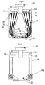
- FIG. 5 shows a section through an optical head 16 and an attached attachment 18, which serves to realize the principle according to the invention.
- the optical head 16 includes a sensor matrix 20 and a receiving optics 22 designed as an objective, which is arranged upstream of the sensor matrix 20.
- the receiving optics 22 extends through a printed circuit board 24 which, on its underside facing away from the sensor matrix 20, carries a multiplicity of LEDs 26 which are arranged around the receiving optics 22.
- the optical head 16 may be completed on its side facing the article 28 with a transmissive disk.
- Attached to the optical head 16 is the aforementioned attachment 18, which extends from the optical head 16 almost to the object 28.
- the cap 18 encloses a substantially annular cavity which the optical axis 30 surrounds the receiving optical system 22, wherein in the attachment 18 a central, with increasing distance from the optical head 16 magnification ß ernde opening 32 is provided which ensures that the object 28 or from the coding arranged thereon light can pass unhindered to the receiving optics 22.
- the inner surfaces 34 of the annular cavity are formed to be reflective or at least reflective so that they are capable of directing light coming from the LEDs 26 within the cavity into its end region facing the article 28. This is illustrated by the light beams shown as arrows according to FIG. 5, which are drawn in the left region of the cavity.
- the attachment 18 In its lower end region, the attachment 18 has an annular light exit surface 36 which does not extend vertically above the code to be read, but extends outside or laterally thereof.
- the reflective inner surfaces 34 of the attachment 18 are arranged such that the light coming from the LEDs 26 is ultimately conducted into the area of the light exit surface 36, where it is inclined in an orientation to the surface of the object 28 or the object thereon located coding from the parallel to the optical axis 30 of the receiving optics 22 extending light exit surface 36 exits, so that ultimately an illumination of the coding according to the already explained in connection with FIG. 2 principle.
- the attachment 18 can in this case represent a separate component which can be coupled to an optical head 12 according to FIGS. 4 a and 4 b and can be connected together with it in the respectively desired orientation with a code reader 10.
- an attachment 18 according to FIG. 5 does not require any power supply and otherwise requires no intervention in the optical head 16, so that it can be mechanically mounted in an extremely simple manner on an optical head 16 and connected thereto.
- FIG. 6 shows a configuration corresponding to the design of the optical head 16 and the shape of the attachment 18 of FIG. 5, so that corresponding reference numerals are also used here.
- optical waveguides 38 are provided, which are held in the end regions of a holding plate 40 in the optical head 16. Specifically, a separate optical waveguide 38 is provided for each LED 26, which ensures that the light from the respective LED 26 in the region of the light exit surface 36, so that the guided light directly from the optical waveguides 38 obliquely to the surface of the article 28 can emerge and thus provides a lighting that largely corresponds to that of FIG. 5.
- a corresponding holding element 42 for example a circular ring, in which the ends of the optical waveguides 38 are fixed.
- a shading element 44 which is e.g. may have a circular ring shape, and extending perpendicular to the optical axis of the receiving optics 22. This shading element 44 serves to prevent light emerging from the ends of the optical waveguides 38 from reaching the receiving optics 22 directly and without reflection from the object 28.
- FIG. 7 has an optical head 16, which is identical to an optical head 16 according to FIG. 5.
- This optical head 16 is coupled according to FIG. 7 with an attachment 18 ', which, like the attachments 18 according to FIGS. 5 and 6, extends almost to the object 28.
- the attachment 18 ' has substantially the shape of a circular cylinder and has at its lower, the article 28 end facing an annular light source 46, which is formed so that from her exiting light obliquely incident on the surface of the article 28.
- the light source 46 must be supplied by the code reader via the optical head 16 with voltage.
- an arrangement according to FIG. 7 can be implemented such that the light source 46 and the LEDs 26 can be activated alternately or jointly.
- FIGS. 8 and 9 each show an optical head 16, as it can be used in conjunction with arrangements according to FIGS. 4 to 7.
- each LED 26 is preceded by a separate lens 48 which, starting from each LED 26, generates directional radiation which, for example, is particularly efficient on reflective inner surfaces 34 an essay 18 shown in FIG. 5 can be passed.
- a corresponding effect can be achieved if the lenses 48 according to FIG. 9 are replaced by diaphragms 50 or ring reflectors.
Landscapes
- Physics & Mathematics (AREA)
- Engineering & Computer Science (AREA)
- Electromagnetism (AREA)
- Artificial Intelligence (AREA)
- Toxicology (AREA)
- General Health & Medical Sciences (AREA)
- Health & Medical Sciences (AREA)
- Computer Vision & Pattern Recognition (AREA)
- General Physics & Mathematics (AREA)
- Theoretical Computer Science (AREA)
- Image Input (AREA)
- Length Measuring Devices By Optical Means (AREA)
- Facsimile Scanning Arrangements (AREA)
Abstract
Description
- Die Erfindung betrifft einen Codeleser mit einer integrierten Lichtquelle zur Ausleuchtung eines Lesebereichs, sowie mit einer Sensormatrix und einer dieser vorgelagerten Empfangsoptik.
- Derartige Codeleser sind aus dem Stand der Technik in vielfachen Ausführungsformen bekannt und werden unter anderem auch dafür eingesetzt, Codierungen zu lesen, die direkt auf das jeweilige Trägermaterial durch eine Verformung desselben aufgebracht wurden. Derartige Codierungen, die beispielsweise als so genannte DPM-Codierungen (Direct Part Marking-Codierungen) bekannt sind, werden beispielsweise erzeugt, indem das Trägermaterial mit einem Hochenergie-Laser oder mittels Nadelprägen ("dot peening") bearbeitet wird. Beiden Verfahren ist gemeinsam, dass an jeweils gewünschten Stellen Ausnehmungen bzw. Vertiefungen im Trägermaterial erzeugt werden, welche dann letztlich in ihrer Gesamtanordnung dem gewünschten Code entsprechen.
DPM-Codierungen werden insbesondere für zweidimensionale Codes eingesetzt, welche beispielsweise aus innerhalb einer Fläche gezielt angeordneten Punkten bestehen, wobei jeder Punkt einer Ausnehmung bzw. Vertiefung im Trägermaterial entspricht. - Das Lesen von DPM-Codierungen gestaltet sich schwierig, wenn der Codeleser senkrecht über der Codierung angeordnet wird, da die im Codeleser integrierte Lichtquelle die Codierung dann unter einem Einfallswinkel beleuchtet, welcher zumindest weitgehend mit der optischen Achse des Codelesers zusammenfällt, was zur Folge hat, dass zwischen den mit Ausnehmungen versehenen Bereichen des Trägermaterials und denjenigen Bereichen, die keine Ausnehmungen aufweisen, kein starker Kontrastunterschied auftritt. Dementsprechend arbeitet man hier üblicherweise nicht mit einer im Codeleser integrierten Lichtquelle, sondern vielmehr mit einer externen, separat vorzusehenden Lichtquelle, die im Sinne einer Dunkelfeldbeleuchtung die Codierung unter einem sehr schrägen Einfallswinkel beleuchtet. Diejenigen Bereiche des Trägermaterials, die keine Ausnehmungen aufweisen, erzeugen in diesem Fall dann eine sehr flache Lichtreflexion, so dass das reflektierte Licht nicht zum Codeleser gelangt und die genannten Bereiche im Codeleser letztlich dunkel erscheinen. Das schräg auf die Ausnehmungen auftreffende Licht wird bei einem schrägen Lichteinfall hingegen in ausreichendem Maße zum Codeleser reflektiert, so dass die Ausnehmungen im Codeleser letztlich hell erscheinen und klar von denjenigen - dunkel erscheinenden - Bereichen unterschieden werden können, die keine Ausnehmungen aufweisen.
- Nachteilig an den beschriebenen bekannten Anordnungen zum Lesen von DPM-Codierungen ist somit die Tatsache, dass die üblicherweise in einem Codeleser vorhandene integrierte Lichtquelle nicht verwendet werden kann und zusätzlich eine externe Lichtquelle vorgesehen werden muss, welche für die beschriebene schräge Beleuchtung der Codierung sorgt. Diese externe Lichtquelle muss darüber hinaus relativ zum Codeleser korrekt justiert werden, was einen zusätzlichen Aufwand bedeutet.
- Eine Aufgabe der Erfindung besteht darin, einen Codeleser der eingangs genannten Art derart weiterzubilden, dass er ohne die Vorsehung einer vom Codeleser getrennten Lichtquelle auch zum Lesen von DPM-Codierungen geeignet ist, wobei die jeweilige Codierung insbesondere mit größtmöglicher Sicherheit erkannt werden soll.
- Diese Aufgabe wird erfindungsgemäß durch die Merkmale des Anspruchs 1 und insbesondere dadurch gelöst, dass sich die Lichtaustrittsfläche der im Codeleser integrierten Lichtquelle im Schärfentiefebereich oder nahe vor dem Schärfentiefebereich der Empfangsoptik des Codelesers befindet.
- Bei aus dem Stand der Technik bekannten Codelesern befindet sich die Lichtaustrittsfläche in der Regel ungefähr im Bereich der Empfangsoptik des Codelesers und nicht in dessen von der Empfangsoptik vergleichsweise weit entferntem Schärfentiefebereich. Eine derartige bekannte Anordnung der Lichtaustrittsfläche im Bereich der Empfangsoptik führt dementsprechend auch immer zu einer Beleuchtung der zu lesenden Codierung unter einem Einfallswinkel, welcher mit der optischen Achse der Empfangsoptik im Wesentlichen übereinstimmt. Erfindungsgemäß wird nun ein solcher Codeleser derart modifiziert, dass die Lichtaustrittsfläche weiter entfernt von der Empfangsoptik, nämlich in im Bereich des Schärfentiefebereichs, konkret in der Regel etwas vor dem Schärfentiefebereich, angeordnet wird, was letztlich bedeutet, dass sich die Lichtaustrittsfläche sehr nahe bei der zu lesenden Codierung befindet, da auch die Codierung im Schärfentiefebereich der Empfangsoptik angeordnet werden muss, um ein korrektes Lesen derselben sicherstellen zu können. Aufgrund der räumlichen Nähe zwischen Lichtaustrittsfläche und Codierung wird es dann erfindungsgemäß möglich, die Codierung unter einem sehr schrägen Einfallswinkel derart zu beleuchten, dass Strahlung, die von solchen Bereichen des Trägermaterials reflektiert wird, welche keine Ausnehmungen aufweisen, nicht zur Empfangsoptik gelangt. Zur Empfangsoptik gelangen in erwünschter Weise nur solche Strahlungsanteile, welche von den Ausnehmungen reflektiert werden, so dass die Codierung einwandfrei erkannt werden kann. Der Winkel zwischen der optischen Achse der Empfangsoptik und den auf die Codierung auftreffenden Lichtstrahlen beträgt sinnvollerweise zwischen 70° und 95°, insbesondere zwischen 80° und 85°.
- Erfindungsgemäß wird also die Vorsehung einer separaten Lichtquelle auf vorteilhafte Art und Weise vermieden, was den wirtschaftlichen Gesamtaufwand der Anordnung verringert und zudem auch gemäß Stand der Technik noch nötige Justiervorgänge zwischen Lichtquelle und Codeleser einspart. Gemäß der Erfindung wird ein in einem einzigen Gehäuse unterzubringendes, einfach handhabbares, kompaktes Gerät bereitgestellt, welches ohne das Erfordernis irgendwelcher zusätzlicher Bauteile dazu geeignet ist, DPM-Codierungen problemlos zu lesen. Erreicht wird dies dadurch, dass sich die Lichtaustrittsfläche der im Codeleser integrierten Lichtquelle deutlich näher am Schärfentiefebereich der Empfangsoptik als an der Empfangsoptik selbst befindet.
- Bevorzugt ist es, wenn sich die Lichtaustrittsfläche im Wesentlichen parallel zur optischen Achse der Empfangsoptik erstreckt. Bei einer derartigen Ausrichtung der Lichtaustrittsfläche kann besonders wirksam Lichtstrahlung erzeugt werden, welche schräg zur Oberfläche der Codierung verläuft. Die Lichtaustrittsfläche kann auch gegenüber der optischen Achse der Empfangsoptik geneigt verlaufen, vorteilhaft ist es aber in jedem Fall, wenn die Lichtaustrittsfläche nicht senkrecht zur optischen Achse der Empfangsoptik verläuft, da es im letztgenannten Fall zwar nicht unmöglich, aber dennoch schwierig wäre, die gewünschte schräge Einstrahlung des von der Lichtquelle des Codelesers stammenden Lichts zu realisieren.
- Besonders vorteilhaft ist es, wenn ein von den restlichen Codeleser-Bestandteilen lösbarer Aufsatz vorgesehen ist, welcher die Lichtaustrittsfläche aufweist. In diesem Fall können dann herkömmliche Codeleser gemäß Stand der Technik erfindungsgemäß modifiziert oder nachgerüstet werden, indem sie mit einem Aufsatz der genannten Art versehen werden, welcher auf geeignete Weise dafür sorgt, dass Licht aus der im Aufsatz befindlichen Lichtaustrittsfläche austritt und dann letztlich schräg auf die zu lesende Codierung auftrifft.
- Bei einer bevorzugten Ausführungsform der Erfindung befindet sich die Lichtquelle im Bereich der Empfangsoptik und/oder der Sensormatrix, wobei zwischen Lichtquelle und Lichtaustrittsfläche Lichtleitelemente angeordnet sind. In diesem Fall ist es dann beispielsweise möglich, wiederum herkömmliche Codeleser gemäß Stand der Technik einzusetzen und auch die in derartigen Codelesern integrierte Lichtquelle zu benutzen. Die Lichtquellen werden nämlich bei Codelesern gemäß Stand der Technik in der Regel im Bereich der Empfangsoptik und/oder im Bereich der Sensormatrix angeordnet, so dass die genannten Lichtleitelemente so positioniert werden können, dass sie das von der vorhandenen Lichtquelle abgestrahlte Licht zu der erfindungsgemäß vorgesehenen Lichtaustrittsfläche leiten. Die Vorsehung einer zusätzlichen Lichtquelle zu der in einem Codeleser gemäß Stand der Technik bereits vorhandenen Lichtquelle ist demgemäß nicht mehr nötig. Diese Ausführungsform lässt sich besonders vorteilhaft realisieren, wenn die Lichtleitelemente sowie die Lichtaustrittsfläche in einem von den restlichen Codeleser-Bestandteilen lösbaren Aufsatz untergebracht werden. Dieser Aufsatz, der dann lediglich reflektierende Flächen und eine beispielsweise als lichtdurchlässige Scheibe ausgestaltete Lichtaustrittsfläche aufweist, kann kostengünstig hergestellt und auf einfache Weise mit Codelesern gemäß Stand der Technik gekoppelt werden. So lässt sich ein erfindungsgemäßer Codeleser mit sehr geringem wirtschaftlichem Aufwand realisieren.
- Die vorstehend erwähnten Lichtleitelemente werden bevorzugt als Lichtwellenleiter und/oder als Anordnung reflektierender Flächen ausgebildet.
- Die erfindungsgemäß eingesetzte Lichtquelle kann aus einer Anordnung von mehreren LEDs bestehen, welche um die optische Achse der Empfangsoptik, insbesondere ringförmig um die optische Achse der Empfangsoptik angeordnet sind. Wenn die von diesen LEDs ausgesandte Strahlung dann in geeigneter Weise, beispielsweise über Lichtwellenleiter oder reflektierende Flächen, zur Lichtaustrittsfläche geleitet wird, lässt sich eine ringförmige, schräge Bestrahlung der zu lesenden Codierung erreichen, bei der die Codierung praktisch aus allen Richtungen beleuchtet wird.
- Insbesondere beim Einsatz von Lichtwellenleitern, aber auch bei der Verwendung reflektierender Flächen als Lichtleitelemente ist es bevorzugt, wenn den LEDs Linsen und/oder Blenden und/oder Ringreflektoren zur Erzeugung einer in Richtung der Lichtleitelemente gerichteten Strahlung zugeordnet sind. Insbesondere kann dabei jeder LED jeweils eine eigene Linse und/oder eine eigene Blende und/oder ein eigener Ringreflektor zugeordnet werden. Auf diese Weise lässt sich die Lichtstrahlung gezielt und mit wenigen Verlusten effizient zu der erfindungsgemäß vorgesehenen Lichtaustrittsfläche leiten.
- Bei einer weiteren Ausführungsform der Erfindung kann sich die Lichtquelle, die insbesondere aus einer Anordnung von mehreren LEDs besteht, einschließlich der Lichtaustrittsfläche im oder nahe vor dem Schärfentiefebereich der Empfangsoptik befinden. Wenn eine derartige Anordnung in Verbindung mit Codelesern gemäß Stand der Technik, welche bereits eine integrierte Lichtquelle aufweisen, eingesetzt werden soll, kann die im Codeleser bereits vorhandene Lichtquelle deaktiviert werden, da die im Schärfentiefebereich der Empfangsoptik vorhandene Lichtquelle für die gewünschte schräge Beleuchtung zu lesender Codierungen sorgt. Ebenso können beide Lichtquellen aber auch wechselweise oder gemeinsam aktiviert werden, um so unterschiedliche Kontrastsituationen zu erzeugen, die dann letztlich ein noch sichereres Erkennen einer Codierung durch einen Vergleich der mit verschiedenen Kontrastsituationen aufgenommenen Bilder ermöglichen.
- Auch bei Vorsehung der Lichtquelle im Schärfentiefebereich der Empfangsoptik kann die Lichtquelle gemeinsam mit der ihr zugeordneten Lichtaustrittsfläche in einem von den restlichen Codeleser-Bestandteilen lösbaren Aufsatz vorgesehen werden, was wiederum die Verwendung mit einem Codeleser gemäß Stand der Technik vereinfacht.
- Besonders bevorzugt ist es, wenn die Lichtquelle und die Empfangsoptik in einem Optikkopf untergebracht werden, welcher gemeinsam mit der erfindungsgemäß positionierten Lichtaustrittsfläche relativ zu den restlichen Codeleser-Bestandteilen in unterschiedlichen Positionen justierbar ist. Auf diese Weise kann ein entsprechend ausgebildeter Codeleser beispielsweise wahlweise mit frontseitigem oder mit seitlichem Lichtaustritt arbeiten und somit an die jeweiligen Einsatzbedingungen angepasst werden. Der Optikkopf mit Lichtquelle und Empfangsoptik bildet dann gemeinsam mit der erfindungsgemäß vorgesehenen Lichtaustrittsfläche und den gegebenenfalls vorgesehenen Lichtleitelementen eine Einheit, welche relativ zu den restlichen Codeleser-Bestandteilen in der jeweils erforderlichen Weise positioniert werden kann.
- Weitere bevorzugte Ausführungsformen der Erfindung sind in den Unteransprüchen beschrieben.
- Die Erfindung wird nachfolgend anhand von Ausführungsbeispielen unter Bezugnahme auf die Zeichnungen erläutert; in diesen zeigen:
- Fig. 1
- ein mit frontaler Beleuchtung aufgenommenes Bild einer DPM-Codierung,
- Fig. 2
- eine Anordnung gemäß Stand der Technik zum Lesen von DPM-Codierungen,
- Fig. 3
- das Bild einer Codierung gemäß Fig. 1, welches von einer Anordnung gemäß Fig. 2 aufgenommen wurde,
- Fig. 4a
- eine dreidimensionale Ansicht eines Codelesers gemäß Stand der Technik mit lösbarem Optikkopf,
- Fig. 4b
- ein Codeleser gemäß Fig. 4a, bei dem die Position des Optikkopfes gegenüber Fig. 4a verändert wurde,
- Fig. 5
- einen Schnitt durch eine erfindungsgemäße Anordnung mit reflektierenden Flächen,
- Fig. 6
- eine Schnittdarstellung einer Anordnung gemäß Fig. 5, bei der die reflektierenden Flächen durch Lichtwellenleiter ersetzt sind,
- Fig. 7
- eine Schnittdarstellung einer erfindungsgemäßen Anordnung mit im Schärfentiefebereich der Empfangsoptik vorgesehenen Lichtquellen,
- Fig. 8
- einen erfindungsgemäß einsetzbaren Optikkopf mit den LEDs des Optikkopfes vorgeordneten Linsen, und
- Fig. 9
- einen erfindungsgemäß einsetzbaren Optikkopf mit den LEDs des Optikkopfes vorgeordneten Blenden.
- Die in Fig. 1 dargestellte Codierung wurde mittels Nadelprägen in einen Metallträger eingebracht und besteht aus einem quadratischen Feld von in einem vorgegebenen Muster angeordneten Vertiefungen, wobei jede Vertiefung durch eine in den Metallträger eingedrückte Nadel erzeugt wurde. Unterhalb des quadratischen Feldes befindet sich eine Anordnung von mehreren Zahlen, die ebenfalls aus einzelnen Vertiefungen gebildet werden.
- Die Codierung gemäß Fig. 1 ist nicht besonders gut zu erkennen, da sie von einem Codeleser bei frontaler Beleuchtung, das heißt bei einer senkrecht zum Trägermaterial verlaufenden Beleuchtungsrichtung, aufgenommen wurde.
- Fig. 2 zeigt eine schematische Darstellung einer Anordnung gemäß Stand der Technik, welche zu einem verbesserten Lesen von DPM-Codierungen, also beispielsweise auch einer Codierung gemäß Fig. 1, geeignet ist. Diese Anordnung besteht aus einer Kamera 2 mit integrierter Sensormatrix, wobei der Sensormatrix eine Empfangsoptik 4 vorgelagert ist. Unterhalb und im Gesichtsfeld der Kamera 2 ist ein Gegenstand 6 vorgesehen, welcher auf seiner der Kamera 2 zugewandten Oberfläche eine DPM-Codierung trägt.
- Ferner ist eine ringförmige Beleuchtungsanordnung 8 vorgesehen, welche sich deutlich näher am Gegenstand 6 als an der Kamera 2 befindet. Der Durchmesser der Beleuchtungsanordnung 8 ist dabei derart gewählt, dass sich die ringförmig angeordneten Lichtquellen der Beleuchtungsanordnung 8 nicht senkrecht oberhalb der Codierung, sondern außerhalb der Codierung befinden. Die Beleuchtungsanordnung 8 ist somit dazu geeignet, die auf dem Gegenstand 6 befindliche Codierung in Richtung der in Fig. 2 eingezeichneten Pfeile von schräg oben zu beleuchten, so dass vom Gegenstand 6 spiegelnd reflektiertes Licht nicht in die Empfangsoptik 4 der Kamera 2 gelangt (siehe strichpunktierter Pfeil der Fig. 2).
- Lediglich derjenige Lichtanteil, der von den Vertiefungen der Codierung reflektiert wird, gelangt zu einem wesentlichen Anteil entlang des Pfeils A zur Empfangsoptik 4 der Kamera 2, so dass die Vertiefungen von der Kamera 2 problemlos erkannt werden können.
- Eine Codierung gemäß Fig. 1, welche von einer Anordnung gemäß Fig. 2 aufgenommen wurde, ist aus Fig. 3 ersichtlich. Fig. 3 zeigt, dass die Kontraste zwischen den mit Vertiefungen versehenen Bereichen des Trägermaterials und denjenigen Bereichen, die keine Vertiefungen aufweisen, deutlich größer sind, als die entsprechenden Kontraste gemäß Fig. 1.
- Wie eingangs bereits erläutert, ist an der Anordnung gemäß Fig. 2 jedoch von Nachteil, dass eine separate Beleuchtungsanordnung 8 vorgesehen werden muss, welche überdies relativ zur Kamera 2 korrekt zu justieren ist.
- Fig. 4a zeigt in dreidimensionaler Ansicht einen Codeleser, der zum Lesen von Codierungen verwendet wird, die keinerlei Ausnehmungen oder Vertiefungen aufweisen. Ein derartiger Codeleser 10 besitzt in seinem stirnseitigen Bereich einen Optikkopf 12, welcher drei rechteckige Seitenflächen und zwei einander gegenüberliegende, dreieckige Stirnflächen aufweist. Eine der Seitenflächen ist dabei als Lichtaustrittsfläche 14 ausgebildet.
- Im Optikkopf 12 befindet sich eine Sensormatrix, der eine Empfangsoptik vorgelagert ist. Um die Empfangsoptik herum sind als Lichtquellen einzelne LEDs angeordnet, welche zur Beleuchtung der zu lesenden Codierung dienen.
- Bei einer Orientierung des Optikkopfes 12 gemäß Fig. 4a tritt das von den LEDs erzeugte Licht in Pfeilrichtung, also seitlich aus dem Codeleser 10 aus.
- Fig. 4b, welche den Codeleser 10 gemäß Fig. 4a in verkleinerter Darstellung zeigt, veranschaulicht, dass der Optikkopf 12 auch in einer gegenüber Fig. 4a verdrehten Anordnung am Codeleser 10 derart befestigt werden kann, dass das von den LEDs erzeugte Licht stirnseitig aus dem Codeleser 10 austritt, wie es der in Fig. 4b eingezeichnete Pfeil veranschaulicht.
- Der Codeleser gemäß den Fig. 4a und 4b kann dementsprechend durch eine geeignete Orientierung seines Optikkopfes 12 für unterschiedliche Anwendungsfälle bzw. Einbausituationen eingesetzt werden. Insbesondere lässt sich der Codeleser 10 gemäß den Fig. 4a und 4b durch die Vorsehung eines Aufsatzes am Optikkopf 12 erfindungsgemäß modifizieren. Ein solcher Aufsatz kann beispielsweise gemäß den Figuren 5 bis 7 ausgebildet sein.
- Fig. 5 zeigt einen Schnitt durch einen Optikkopf 16 sowie einen daran befestigten Aufsatz 18, welcher zur Verwirklichung des erfindungsgemäßen Prinzips dient.
- Der Optikkopf 16 beinhaltet eine Sensormatrix 20 sowie eine als Objektiv ausgestaltete Empfangsoptik 22, die der Sensormatrix 20 vorgelagert ist.
- Die Empfangsoptik 22 erstreckt sich dabei durch eine Platine 24 hindurch, die auf ihrer der Sensormatrix 20 abgewandten Unterseite eine Vielzahl von LEDs 26 trägt, die um die Empfangsoptik 22 herum angeordnet sind.
- Im Gesichtsfelder Sensormatrix 20 bzw. der Einheit aus Sensormatrix 20 und Empfangsoptik 22 befindet sich ein Gegenstand 28, auf welchem eine DPM-Codierung angebracht ist. Der Optikkopf 16 kann auf seiner dem Gegenstand 28 zugewandten Seite mit einer durchlässigen Scheibe abgeschlossen sein.
- Am Optikkopf 16 ist der genannte Aufsatz 18 befestigt, welcher sich vom Optikkopf 16 bis fast zum Gegenstand 28 erstreckt. Dabei umschließt der Aufsatz 18 einen im Wesentlichen ringförmigen Hohlraum, welcher die optische Achse 30 der Empfangsoptik 22 umgibt, wobei im Aufsatz 18 eine zentrale, sich mit zunehmendem Abstand vom Optikkopf 16 vergrößernde Öffnung 32 vorgesehen ist, die sicherstellt, dass vom Gegenstand 28 bzw. von der darauf angeordneten Codierung kommendes Licht ungehindert zur Empfangsoptik 22 gelangen kann.
- Die Innenflächen 34 des ringförmigen Hohlraums sind spiegelnd oder zumindest reflektierend ausgebildet, so dass sie dazu geeignet sind, von den LEDs 26 kommendes Licht innerhalb des Hohlraums in seinen dem Gegenstand 28 zugewandten Endbereich zu leiten. Dies veranschaulichen die als Pfeile dargestellten Lichtstrahlen gemäß Fig. 5, die im linken Bereich des Hohlraums eingezeichnet sind.
- In seinem unteren Endbereich besitzt der Aufsatz 18 eine kreisringförmige Lichtaustrittsfläche 36, welche sich nicht senkrecht oberhalb der zu lesenden Codierung, sondern außerhalb bzw. seitlich derselben erstreckt.
- Wie Fig. 5 verdeutlicht, sind die reflektierenden Innenflächen 34 des Aufsatzes 18 so angeordnet, dass das von den LEDs 26 kommende Licht letztlich in den Bereich der Lichtaustrittsfläche 36 geleitet wird, wo es in einer Orientierung schräg zur Oberfläche des Gegenstands 28 bzw. der darauf befindlichen Codierung aus der parallel zur optischen Achse 30 der Empfangsoptik 22 verlaufenden Lichtaustrittsfläche 36 austritt, so dass letztlich eine Beleuchtung der Codierung entsprechend dem in Verbindung mit Fig. 2 bereits erläuterten Prinzip erfolgt.
- Der Aufsatz 18 kann dabei ein separates Bauteil darstellen, welches mit einem Optikkopf 12 gemäß den Fig. 4a und 4b koppelbar und gemeinsam mit diesem in der jeweils gewünschten Orientierung mit einem Codeleser 10 verbindbar ist. Besonders vorteilhaft ist in diesem Zusammenhang, dass ein Aufsatz 18 gemäß Fig. 5 keinerlei Stromversorgung benötigt und auch sonst kein Eingreifen in dem Optikkopf 16 erfordert, so dass er in äußerst einfacher Weise auf einen Optikkopf 16 mechanisch aufgesetzt und mit diesem verbunden werden kann.
- Fig. 6 zeigt eine in der Ausbildung des Optikkopfs 16 und der Form des Aufsatzes 18 der Fig. 5 entsprechende Anordnung, so dass hier auch entsprechende Bezugszeichen verwendet sind.
- Der Unterschied gegenüber Fig. 5 besteht darin, dass anstelle der reflektierenden Innenflächen 34 Lichtwellenleiter 38 vorgesehen sind, die im Optikkopf 16 in deren Endbereichen von einer Halteplatte 40 gehalten sind. Konkret ist für jede LED 26 ein separater Lichtwellenleiter 38 vorgesehen, welcher dafür sorgt, das Licht von der jeweiligen LED 26 in den Bereich der Lichtaustrittsfläche 36 zu leiten, so dass das derart geführte Licht direkt aus den Lichtwellenleitern 38 schräg zur Oberfläche des Gegenstands 28 austreten kann und somit für eine Beleuchtung sorgt, die derjenigen gemäß Fig. 5 weitgehend entspricht. Um für die richtige Orientierung der Lichtwellenleiter 38 im Bereich der Lichtaustrittsfläche 36 zu sorgen, ist auch dort ein entsprechendes, beispielsweise kreisringförmig ausgebildetes Halteelement 42 vorhanden, in welchem die Enden der Lichtwellenleiter 38 fixiert sind.
- Oberhalb der Lichtaustrittsfläche 36 steht radial nach innen ein Abschattungselement 44 hervor, welches z.B. eine Kreisringform besitzen kann, und sich senkrecht zur optischen Achse der Empfangsoptik 22 erstreckt. Dieses Abschattungselement 44 dient dazu, zu verhindern, dass aus den Enden der Lichtwellenleiter 38 austretendes Licht direkt und ohne Reflexion am Gegenstand 28 zur Empfangsoptik 22 gelangt.
- Die in Fig. 7 dargestellte Anordnung besitzt einen Optikkopf 16, welcher identisch zu einem Optikkopf 16 gemäß Fig. 5 ausgebildet ist. Dieser Optikkopf 16 ist gemäß Fig. 7 mit einem Aufsatz 18' gekoppelt, welcher sich ebenso wie die Aufsätze 18 gemäß den Fig. 5 und 6 fast bis zum Gegenstand 28 erstreckt. Der Aufsatz 18' weist im Wesentlichen die Form eines Kreiszylinders auf und besitzt an seinem unteren, dem Gegenstand 28 zugewandten Endbereich eine kreisringförmige Lichtquelle 46, welche so ausgebildet ist, dass aus ihr austretendes Licht schräg auf die Oberfläche des Gegenstands 28 auftrifft. Die Lichtquelle 46 muss dabei vom Codeleser über den Optikkopf 16 mit Spannung versorgt werden. Alternativ ist es auch möglich, im Aufsatz 18' eine Spannungsquelle in Form einer Batterie oder eines Akkus vorzusehen.
- Wie bereits erläutert, kann eine Anordnung gemäß Fig. 7 so ausgeführt werden, dass die Lichtquelle 46 und die LEDs 26 wechselweise oder auch gemeinsam aktiviert werden können.
- Die Fig. 8 und 9 zeigen jeweils einen Optikkopf 16, wie er in Verbindung mit Anordnungen gemäß den Fig. 4 bis 7 zum Einsatz gelangen kann.
- Der Optikkopf gemäß Fig. 8 ist gegenüber dem Optikkopf 16 der Fig. 5 bis 7 dadurch verbessert, dass jeder LED 26 eine eigene Linse 48 vorgeschaltet ist, die ausgehend von jeder LED 26 eine gerichtete Strahlung erzeugt, die beispielsweise besonders effizient auf reflektierende Innenflächen 34 eines Aufsatzes 18 gemäß Fig. 5 geleitet werden kann.
- Ein entsprechender Effekt lässt sich erzielen, wenn die Linsen 48 gemäß Fig. 9 durch Blenden 50 oder Ringreflektoren ersetzt werden.
-
- 2
- Kamera
- 4
- Empfangsoptik
- 6
- Gegenstand
- 8
- Beleuchtungsanordnung
- 10
- Codeleser
- 12
- Optikkopf
- 14
- Lichtaustrittsfläche
- 16
- Lichtoptikkopf
- 18
- Aufsatz
- 20
- Sensormatrix
- 22
- Empfangsoptik
- 24
- Platine
- 26
- LEDs
- 28
- Gegenstand
- 30
- optische Achse
- 32
- Öffnung
- 34
- Innenflächen
- 36
- Lichtaustrittsfläche
- 38
- Lichtwellenleiter
- 40
- Halteplatte
- 42
- Halteelement
- 44
- Abschattungselement
- 46
- Lichtquelle
- 48
- Linsen
- 50
- Blenden
Claims (10)
- Codeleser mit einer integrierten Lichtquelle (26, 46) zur Ausleuchtung eines Lesebereichs, einer Sensormatrix (20) und einer dieser vorgelagerten Empfangsoptik (22),
dadurch gekennzeichnet ,
dass sich die Lichtaustrittsfläche (36) der Lichtquelle (26, 46) im Schärfentiefebereich oder nahe vor dem Schärfentiefebereich der Empfangsoptik (22) befindet. - Codeleser nach Anspruch 1,
dadurch gekennzeichnet ,
dass sich die Lichtaustrittsfläche (36) in wesentlichen parallel zur optischen Achse (30) der Empfangsoptik (22) erstreckt. - Codeleser nach einem der vorhergehenden Ansprüche,
dadurch gekennzeichnet ,
dass ein von den restlichen Codeleser-Bestandteilen lösbarer Aufsatz (18, 18') vorgesehen ist, welcher die Lichtaustrittsfläche (36) aufweist. - Codeleser nach einem der vorhergehenden Ansprüche,
dadurch gekennzeichnet ,
dass sich die Lichtquelle (26) im Bereich der Empfangsoptik (22) und/oder der Sensormatrix (20) befindet, wobei zwischen Lichtquelle (26) und Lichtaustrittsfläche (36) Lichtleitelemente (34, 38) angeordnet sind. - Codeleser nach Anspruch 4,
dadurch gekennzeichnet,
dass die Lichtleitelemente als Lichtwellenleiter (38) und/oder als Anordnung reflektierender Flächen (34) ausgebildet sind. - Codeleser nach einem der vorhergehenden Ansprüche,
dadurch gekennzeichnet ,
dass die Lichtquelle (26) aus einer Anordnung von mehreren LEDs (26) besteht, welche um die optische Achse (30) der Empfangsoptik (22) angeordnet sind. - Codeleser nach einem der Ansprüche 4 bis 6,
dadurch gekennzeichnet ,
dass den LEDs (26) Linsen (48) und/oder Blenden (50) zur Erzeugung einer in Richtung der Lichtleitelemente (34, 38) gerichteten Strahlung zugeordnet sind, wobei insbesondere jeder LED (26) jeweils eine Linse (48) und/oder eine Blende (50) und/oder ein Ringreflektor zugeordnet ist. - Codeleser nach einem der Ansprüche 1 bis 3,
dadurch gekennzeichnet ,
dass sich die Lichtquelle (46), die insbesondere aus einer Anordnung von mehreren LEDs besteht, einschließlich der Lichtaustrittsfläche (36) im oder nahe vor dem Schärfentiefebereich der Empfangsoptik (22) befindet. - Codeleser nach Anspruch 8,
dadurch gekennzeichnet ,
dass die Lichtquelle (46) gemeinsam mit der ihr zugeordneten Lichtaustrittfläche (36) in einem vom den restlichen Codeleser-Bestandteilen lösbaren Aufsatz (18') vorgesehen ist. - Codeleser nach einem der vorhergehenden Ansprüche,
dadurch gekennzeichnet ,
dass die Lichtquelle (26, 46) und die Empfangsoptik (22) in einem Optikkopf untergebracht sind, welcher relativ zu den restlichen Codeleser-Bestandteilen in unterschiedlichen Positionen justierbar ist.
Priority Applications (1)
| Application Number | Priority Date | Filing Date | Title |
|---|---|---|---|
| EP11003461A EP2343669A1 (de) | 2005-02-07 | 2006-01-13 | Codeleser |
Applications Claiming Priority (1)
| Application Number | Priority Date | Filing Date | Title |
|---|---|---|---|
| DE102005005536A DE102005005536A1 (de) | 2005-02-07 | 2005-02-07 | Codeleser |
Related Child Applications (1)
| Application Number | Title | Priority Date | Filing Date |
|---|---|---|---|
| EP11003461.8 Division-Into | 2011-04-27 |
Publications (3)
| Publication Number | Publication Date |
|---|---|
| EP1688861A2 true EP1688861A2 (de) | 2006-08-09 |
| EP1688861A3 EP1688861A3 (de) | 2007-12-19 |
| EP1688861B1 EP1688861B1 (de) | 2011-09-07 |
Family
ID=36283686
Family Applications (2)
| Application Number | Title | Priority Date | Filing Date |
|---|---|---|---|
| EP11003461A Withdrawn EP2343669A1 (de) | 2005-02-07 | 2006-01-13 | Codeleser |
| EP06000754A Expired - Lifetime EP1688861B1 (de) | 2005-02-07 | 2006-01-13 | Codeleser |
Family Applications Before (1)
| Application Number | Title | Priority Date | Filing Date |
|---|---|---|---|
| EP11003461A Withdrawn EP2343669A1 (de) | 2005-02-07 | 2006-01-13 | Codeleser |
Country Status (4)
| Country | Link |
|---|---|
| US (1) | US7510120B2 (de) |
| EP (2) | EP2343669A1 (de) |
| AT (1) | ATE523853T1 (de) |
| DE (1) | DE102005005536A1 (de) |
Cited By (3)
| Publication number | Priority date | Publication date | Assignee | Title |
|---|---|---|---|---|
| WO2008042324A2 (en) | 2006-09-29 | 2008-04-10 | Microscan Systems, Inc. | Systems and/or devices for camera-based inspections |
| EP2913623A1 (de) * | 2014-02-27 | 2015-09-02 | GEA Seguridad, S.L. | Leser für Waffenbeschriftung |
| WO2022152908A1 (de) * | 2021-01-18 | 2022-07-21 | Ioss Intelligente Optische Sensoren & Systeme Gmbh | Verfahren und system zur verifikation einer oberflächenstruktur eines objekts und passives vorsatzmodul |
Families Citing this family (25)
| Publication number | Priority date | Publication date | Assignee | Title |
|---|---|---|---|---|
| US7886979B2 (en) * | 2006-09-19 | 2011-02-15 | Microscan Systems, Inc. | Methods for illuminating barcodes |
| US7857224B2 (en) | 2006-09-19 | 2010-12-28 | Microscan Systems, Inc. | Devices and/or systems for automatically imaging barcodes |
| US7822335B1 (en) | 2006-09-21 | 2010-10-26 | Microscan Systems, Inc. | Lens protector |
| US8032017B2 (en) * | 2006-09-29 | 2011-10-04 | Microscan Systems, Inc. | Methods for providing diffuse light |
| US7978970B2 (en) * | 2006-09-29 | 2011-07-12 | Microscan Systems, Inc. | Systems and/or devices for providing diffuse light |
| US7877003B2 (en) * | 2007-06-20 | 2011-01-25 | Microscan Systems, Inc. | Devices, systems, and methods regarding images |
| DE102007043609B4 (de) | 2007-09-13 | 2014-05-28 | Ioss Intelligente Optische Sensoren & Systeme Gmbh | Integrierte Beleuchtungsvorrichtung für einen optischen Codeleser |
| US8028913B2 (en) * | 2007-09-28 | 2011-10-04 | Symbol Technologies, Inc. | Arrangement for and method of uniformly illuminating direct part markings to be imaged and electro-optically read |
| US8894260B2 (en) * | 2009-03-31 | 2014-11-25 | Sicpa Holding Sa | Annular light guide illuminator and optical scanner |
| US8000594B2 (en) * | 2009-07-02 | 2011-08-16 | Microscan Systems, Inc. | Diffuse reflective illuminator |
| US8768159B2 (en) | 2009-07-10 | 2014-07-01 | Microscan Systems, Inc. | Combination dark field and bright field illuminator |
| US8107808B2 (en) | 2009-07-10 | 2012-01-31 | Microscan Systems, Inc. | Combination dark field and bright field illuminator |
| DE202010006634U1 (de) | 2010-05-10 | 2011-10-05 | Sick Ag | Optoelektronische Lesevorrichtung zur Erfassung von Codes |
| DE102010032469B4 (de) | 2010-07-28 | 2014-12-04 | Ioss Intelligente Optische Sensoren & Systeme Gmbh | Verfahren und Vorrichtung zum Lesen von Codes auf Solarzellen-Wafern |
| US9185306B1 (en) | 2014-05-15 | 2015-11-10 | Symbol Technologies, Llc | Imaging module and reader for, and method of, illuminating and imaging targets to be read over an extended range of working distances |
| US9811705B1 (en) | 2016-05-10 | 2017-11-07 | Datalogic Ip Tech S.R.L. | Illumination system with active element for generating different illumination patterns for a data reader |
| CN106022195B (zh) * | 2016-06-07 | 2018-10-12 | 曾林旺 | 360度全角广域扫描头 |
| US9569653B1 (en) | 2016-06-13 | 2017-02-14 | Datalogic IP Tech, S.r.l. | Dark field illumination system obtained in a tilted plane |
| CN107944315B (zh) | 2016-10-12 | 2023-08-04 | 手持产品公司 | 移动成像条形码扫描仪 |
| WO2018209580A1 (en) | 2017-05-17 | 2018-11-22 | Hand Held Products, Inc. | Multi-functional optical illuminators |
| EP3635611B1 (de) | 2017-06-06 | 2021-04-21 | Sicpa Holding Sa | Beleuchtungsvorrichtung für ein optisches system einer leseeinrichtung |
| US10216969B2 (en) | 2017-07-10 | 2019-02-26 | Hand Held Products, Inc. | Illuminator for directly providing dark field and bright field illumination |
| US10210364B1 (en) | 2017-10-31 | 2019-02-19 | Hand Held Products, Inc. | Direct part marking scanners including dome diffusers with edge illumination assemblies |
| DE102018103544B3 (de) | 2018-02-16 | 2018-10-18 | Sick Ag | Kamera und Verfahren zur Erfassung von Bilddaten |
| DE102020134734A1 (de) | 2020-12-22 | 2022-06-23 | Ioss Intelligente Optische Sensoren & Systeme Gmbh | Vorsatzoptik, System und Verfahren zur Verwendung einer Vorsatzoptik |
Citations (2)
| Publication number | Priority date | Publication date | Assignee | Title |
|---|---|---|---|---|
| WO1999049347A1 (en) | 1998-03-20 | 1999-09-30 | Auto Image Id, Inc. | Target illumination device |
| US20020000472A1 (en) | 1999-08-04 | 2002-01-03 | John R. Hattersley | Optical symbol scanner with low angle illumination |
Family Cites Families (33)
| Publication number | Priority date | Publication date | Assignee | Title |
|---|---|---|---|---|
| US5477044A (en) * | 1994-07-22 | 1995-12-19 | Intermec Corporation | Symbology reader with a variable orientation head |
| US5825011A (en) * | 1994-12-26 | 1998-10-20 | Kabushiki Kaisha Tec | Handle like reading unit for use in code reading apparatus and having plural light reflectors and direct light shielding plate |
| US5786586A (en) * | 1995-01-17 | 1998-07-28 | Welch Allyn, Inc. | Hand-held optical reader having a detachable lens-guide assembly |
| US5874686A (en) * | 1995-10-31 | 1999-02-23 | Ghias; Asif U. | Apparatus and method for searching a melody |
| US6105869A (en) * | 1997-10-31 | 2000-08-22 | Microscan Systems, Incorporated | Symbol reading device including optics for uniformly illuminating symbology |
| US6247645B1 (en) * | 1999-01-25 | 2001-06-19 | International Business Machines Corporation | Optical reader with combined housing and light pipe |
| US6408272B1 (en) * | 1999-04-12 | 2002-06-18 | General Magic, Inc. | Distributed voice user interface |
| US6595422B1 (en) * | 1999-06-23 | 2003-07-22 | Assure Systems, Inc. | Bar code reader |
| GB9918611D0 (en) * | 1999-08-07 | 1999-10-13 | Sibelius Software Ltd | Music database searching |
| US6941275B1 (en) * | 1999-10-07 | 2005-09-06 | Remi Swierczek | Music identification system |
| US7392185B2 (en) * | 1999-11-12 | 2008-06-24 | Phoenix Solutions, Inc. | Speech based learning/training system using semantic decoding |
| US20030182113A1 (en) * | 1999-11-22 | 2003-09-25 | Xuedong Huang | Distributed speech recognition for mobile communication devices |
| WO2001069575A1 (en) * | 2000-03-13 | 2001-09-20 | Perception Digital Technology (Bvi) Limited | Melody retrieval system |
| GB2364480B (en) * | 2000-06-30 | 2004-07-14 | Mitel Corp | Method of using speech recognition to initiate a wireless application (WAP) session |
| FI20002161L (fi) * | 2000-09-29 | 2002-03-30 | Nokia Mobile Phones Ltd | Menetelmä ja järjestelmä melodian tunnistamiseksi |
| US7027987B1 (en) * | 2001-02-07 | 2006-04-11 | Google Inc. | Voice interface for a search engine |
| DE10113426A1 (de) * | 2001-03-19 | 2002-09-26 | Gavitec Gmbh | Lesegerät mit einer Bildaufnahmeeinheit zum Lesen eines Codes und Verfahren zum Lesen eines Codes |
| JP4003483B2 (ja) * | 2002-02-28 | 2007-11-07 | 株式会社デンソーウェーブ | 情報コード読取装置 |
| US20030171926A1 (en) * | 2002-03-07 | 2003-09-11 | Narasimha Suresh | System for information storage, retrieval and voice based content search and methods thereof |
| CN1703734A (zh) * | 2002-10-11 | 2005-11-30 | 松下电器产业株式会社 | 从声音确定音符的方法和装置 |
| JP4258232B2 (ja) * | 2003-03-03 | 2009-04-30 | 株式会社デンソーウェーブ | 光学的情報読取装置 |
| US7028901B2 (en) * | 2003-07-17 | 2006-04-18 | Symbol Technologies, Inc. | System and method for reading and decoding optical codes using multiple color illumination |
| US6824061B1 (en) * | 2003-08-01 | 2004-11-30 | Industrial Data Entry Automation System Incorporated | Phosphorescent optical symbol scanner |
| US20050086052A1 (en) * | 2003-10-16 | 2005-04-21 | Hsuan-Huei Shih | Humming transcription system and methodology |
| US7823783B2 (en) * | 2003-10-24 | 2010-11-02 | Cognex Technology And Investment Corporation | Light pipe illumination system and method |
| US20050111633A1 (en) * | 2003-11-25 | 2005-05-26 | Osborne Jason T. | System and method for voice enabled information retrieval |
| WO2005057429A1 (en) * | 2003-12-08 | 2005-06-23 | Koninklijke Philips Electronics N.V. | Searching in a melody database |
| US20050215239A1 (en) * | 2004-03-26 | 2005-09-29 | Nokia Corporation | Feature extraction in a networked portable device |
| US7617984B2 (en) * | 2004-12-16 | 2009-11-17 | Cognex Technology And Investment Corporation | Hand held symbology reader illumination diffuser |
| JP4287386B2 (ja) * | 2005-01-31 | 2009-07-01 | 株式会社東芝 | 情報検索システム、方法及びプログラム |
| KR20060112633A (ko) * | 2005-04-28 | 2006-11-01 | (주)나요미디어 | 노래 평가 시스템 및 방법 |
| EP1785891A1 (de) * | 2005-11-09 | 2007-05-16 | Sony Deutschland GmbH | Musikabfrage mittels 3D-Suchalgorithmus |
| US7788279B2 (en) * | 2005-11-10 | 2010-08-31 | Soundhound, Inc. | System and method for storing and retrieving non-text-based information |
-
2005
- 2005-02-07 DE DE102005005536A patent/DE102005005536A1/de not_active Withdrawn
-
2006
- 2006-01-13 EP EP11003461A patent/EP2343669A1/de not_active Withdrawn
- 2006-01-13 EP EP06000754A patent/EP1688861B1/de not_active Expired - Lifetime
- 2006-01-13 AT AT06000754T patent/ATE523853T1/de active
- 2006-01-25 US US11/339,382 patent/US7510120B2/en active Active
Patent Citations (2)
| Publication number | Priority date | Publication date | Assignee | Title |
|---|---|---|---|---|
| WO1999049347A1 (en) | 1998-03-20 | 1999-09-30 | Auto Image Id, Inc. | Target illumination device |
| US20020000472A1 (en) | 1999-08-04 | 2002-01-03 | John R. Hattersley | Optical symbol scanner with low angle illumination |
Cited By (5)
| Publication number | Priority date | Publication date | Assignee | Title |
|---|---|---|---|---|
| WO2008042324A2 (en) | 2006-09-29 | 2008-04-10 | Microscan Systems, Inc. | Systems and/or devices for camera-based inspections |
| WO2008042324A3 (en) * | 2006-09-29 | 2008-07-03 | Siemens Energy & Automat | Systems and/or devices for camera-based inspections |
| US8374498B2 (en) | 2006-09-29 | 2013-02-12 | Microscan Systems, Inc. | Systems and/or devices for camera-based inspections |
| EP2913623A1 (de) * | 2014-02-27 | 2015-09-02 | GEA Seguridad, S.L. | Leser für Waffenbeschriftung |
| WO2022152908A1 (de) * | 2021-01-18 | 2022-07-21 | Ioss Intelligente Optische Sensoren & Systeme Gmbh | Verfahren und system zur verifikation einer oberflächenstruktur eines objekts und passives vorsatzmodul |
Also Published As
| Publication number | Publication date |
|---|---|
| EP1688861A3 (de) | 2007-12-19 |
| EP1688861B1 (de) | 2011-09-07 |
| EP2343669A1 (de) | 2011-07-13 |
| ATE523853T1 (de) | 2011-09-15 |
| DE102005005536A1 (de) | 2006-08-10 |
| US20060175409A1 (en) | 2006-08-10 |
| US7510120B2 (en) | 2009-03-31 |
Similar Documents
| Publication | Publication Date | Title |
|---|---|---|
| EP1688861B1 (de) | Codeleser | |
| DE19834374B4 (de) | Drehknopf eines Steuergerätes | |
| EP1880139B1 (de) | Led-beleuchtungsmodul | |
| DE10291122B4 (de) | Lesegerät mit einer Bildaufnahmeeinheit zum Lesen eines Codes und Verfahren zum Lesen eines Codes | |
| EP2507579B1 (de) | Visiereinrichtung | |
| DE69033501T2 (de) | Beleuchtungskörper mit Linse zur Strahlformung | |
| DE102005019093A1 (de) | Fahrzeugleuchte mit einem mehrgliedrig gebildeten Lichtleiter | |
| DE102010021939A1 (de) | Beleuchtungsvorrichtung für Fahrzeuge | |
| DE112011101860B4 (de) | Außenspiegel-Anordnung mit einem Gehäuse umfassend eine Schaltkreisplatine mit einer Mehrzahl an lichtemittierenden Dioden | |
| EP2502784B1 (de) | Fahrzeugleuchte, insbesondere zur Beleuchtung des Innenraums des Fahrzeugs | |
| DE102008036845A1 (de) | Beleuchtungsvorrichtung | |
| DE102013108800B4 (de) | Beleuchtungsvorrichtung und Verfahren zum Erzeugen eines Beleuchtungsfeldes | |
| DE102017108545A1 (de) | Leuchte für eine Kraftfahrzeugkarosserie | |
| DE102011112285A1 (de) | Lichtformung mittels LED-Lichtquelle | |
| DE102013007856A1 (de) | Lichtleitkörper und Leuchtvorrichtung mit dem Lichtleitkörper | |
| EP2871411B2 (de) | Optisches Element für eine Leuchte, sowie Leuchte | |
| DE102009015382B4 (de) | Beleuchtungseinrichtung für einen Zeiger eines Zeigerinstruments, Zeigerinstrument und Kraftfahrzeug | |
| EP2850362B1 (de) | Kontrollleuchte | |
| EP3211470B1 (de) | Vorrichtung zur beleuchtung einer zielmarke | |
| EP0978683A1 (de) | OPtishe Anzeigevorrichtung | |
| EP1507228B1 (de) | Optischer Codeleser | |
| DE102017127355B4 (de) | Leuchte für eine Kraftfahrzeugkarosserie | |
| DE102018133386A1 (de) | Leuchte | |
| EP2052284B1 (de) | Fahrzeugscheinwerfer | |
| EP0741275B1 (de) | Optisches Zielhilfegerät |
Legal Events
| Date | Code | Title | Description |
|---|---|---|---|
| PUAI | Public reference made under article 153(3) epc to a published international application that has entered the european phase |
Free format text: ORIGINAL CODE: 0009012 |
|
| AK | Designated contracting states |
Kind code of ref document: A2 Designated state(s): AT BE BG CH CY CZ DE DK EE ES FI FR GB GR HU IE IS IT LI LT LU LV MC NL PL PT RO SE SI SK TR |
|
| AX | Request for extension of the european patent |
Extension state: AL BA HR MK YU |
|
| RAP1 | Party data changed (applicant data changed or rights of an application transferred) |
Owner name: SICK AG |
|
| PUAL | Search report despatched |
Free format text: ORIGINAL CODE: 0009013 |
|
| AK | Designated contracting states |
Kind code of ref document: A3 Designated state(s): AT BE BG CH CY CZ DE DK EE ES FI FR GB GR HU IE IS IT LI LT LU LV MC NL PL PT RO SE SI SK TR |
|
| AX | Request for extension of the european patent |
Extension state: AL BA HR MK YU |
|
| 17P | Request for examination filed |
Effective date: 20080519 |
|
| AKX | Designation fees paid |
Designated state(s): AT BE BG CH CY CZ DE DK EE ES FI FR GB GR HU IE IS IT LI LT LU LV MC NL PL PT RO SE SI SK TR |
|
| 17Q | First examination report despatched |
Effective date: 20100226 |
|
| GRAP | Despatch of communication of intention to grant a patent |
Free format text: ORIGINAL CODE: EPIDOSNIGR1 |
|
| GRAS | Grant fee paid |
Free format text: ORIGINAL CODE: EPIDOSNIGR3 |
|
| GRAA | (expected) grant |
Free format text: ORIGINAL CODE: 0009210 |
|
| REG | Reference to a national code |
Ref country code: GB Ref legal event code: FG4D Free format text: NOT ENGLISH |
|
| REG | Reference to a national code |
Ref country code: CH Ref legal event code: EP |
|
| REG | Reference to a national code |
Ref country code: IE Ref legal event code: FG4D Free format text: LANGUAGE OF EP DOCUMENT: GERMAN |
|
| REG | Reference to a national code |
Ref country code: DE Ref legal event code: R096 Ref document number: 502006010095 Country of ref document: DE Effective date: 20111103 |
|
| REG | Reference to a national code |
Ref country code: NL Ref legal event code: VDEP Effective date: 20110907 |
|
| PG25 | Lapsed in a contracting state [announced via postgrant information from national office to epo] |
Ref country code: SE Free format text: LAPSE BECAUSE OF FAILURE TO SUBMIT A TRANSLATION OF THE DESCRIPTION OR TO PAY THE FEE WITHIN THE PRESCRIBED TIME-LIMIT Effective date: 20110907 Ref country code: FI Free format text: LAPSE BECAUSE OF FAILURE TO SUBMIT A TRANSLATION OF THE DESCRIPTION OR TO PAY THE FEE WITHIN THE PRESCRIBED TIME-LIMIT Effective date: 20110907 Ref country code: LT Free format text: LAPSE BECAUSE OF FAILURE TO SUBMIT A TRANSLATION OF THE DESCRIPTION OR TO PAY THE FEE WITHIN THE PRESCRIBED TIME-LIMIT Effective date: 20110907 |
|
| LTIE | Lt: invalidation of european patent or patent extension |
Effective date: 20110907 |
|
| PG25 | Lapsed in a contracting state [announced via postgrant information from national office to epo] |
Ref country code: LV Free format text: LAPSE BECAUSE OF FAILURE TO SUBMIT A TRANSLATION OF THE DESCRIPTION OR TO PAY THE FEE WITHIN THE PRESCRIBED TIME-LIMIT Effective date: 20110907 Ref country code: CY Free format text: LAPSE BECAUSE OF FAILURE TO SUBMIT A TRANSLATION OF THE DESCRIPTION OR TO PAY THE FEE WITHIN THE PRESCRIBED TIME-LIMIT Effective date: 20110907 Ref country code: SI Free format text: LAPSE BECAUSE OF FAILURE TO SUBMIT A TRANSLATION OF THE DESCRIPTION OR TO PAY THE FEE WITHIN THE PRESCRIBED TIME-LIMIT Effective date: 20110907 Ref country code: GR Free format text: LAPSE BECAUSE OF FAILURE TO SUBMIT A TRANSLATION OF THE DESCRIPTION OR TO PAY THE FEE WITHIN THE PRESCRIBED TIME-LIMIT Effective date: 20111208 |
|
| REG | Reference to a national code |
Ref country code: IE Ref legal event code: FD4D |
|
| PG25 | Lapsed in a contracting state [announced via postgrant information from national office to epo] |
Ref country code: IE Free format text: LAPSE BECAUSE OF FAILURE TO SUBMIT A TRANSLATION OF THE DESCRIPTION OR TO PAY THE FEE WITHIN THE PRESCRIBED TIME-LIMIT Effective date: 20110907 Ref country code: CZ Free format text: LAPSE BECAUSE OF FAILURE TO SUBMIT A TRANSLATION OF THE DESCRIPTION OR TO PAY THE FEE WITHIN THE PRESCRIBED TIME-LIMIT Effective date: 20110907 Ref country code: SK Free format text: LAPSE BECAUSE OF FAILURE TO SUBMIT A TRANSLATION OF THE DESCRIPTION OR TO PAY THE FEE WITHIN THE PRESCRIBED TIME-LIMIT Effective date: 20110907 Ref country code: IS Free format text: LAPSE BECAUSE OF FAILURE TO SUBMIT A TRANSLATION OF THE DESCRIPTION OR TO PAY THE FEE WITHIN THE PRESCRIBED TIME-LIMIT Effective date: 20120107 |
|
| PG25 | Lapsed in a contracting state [announced via postgrant information from national office to epo] |
Ref country code: PT Free format text: LAPSE BECAUSE OF FAILURE TO SUBMIT A TRANSLATION OF THE DESCRIPTION OR TO PAY THE FEE WITHIN THE PRESCRIBED TIME-LIMIT Effective date: 20120109 Ref country code: PL Free format text: LAPSE BECAUSE OF FAILURE TO SUBMIT A TRANSLATION OF THE DESCRIPTION OR TO PAY THE FEE WITHIN THE PRESCRIBED TIME-LIMIT Effective date: 20110907 Ref country code: RO Free format text: LAPSE BECAUSE OF FAILURE TO SUBMIT A TRANSLATION OF THE DESCRIPTION OR TO PAY THE FEE WITHIN THE PRESCRIBED TIME-LIMIT Effective date: 20110907 Ref country code: EE Free format text: LAPSE BECAUSE OF FAILURE TO SUBMIT A TRANSLATION OF THE DESCRIPTION OR TO PAY THE FEE WITHIN THE PRESCRIBED TIME-LIMIT Effective date: 20110907 Ref country code: NL Free format text: LAPSE BECAUSE OF FAILURE TO SUBMIT A TRANSLATION OF THE DESCRIPTION OR TO PAY THE FEE WITHIN THE PRESCRIBED TIME-LIMIT Effective date: 20110907 |
|
| PLBE | No opposition filed within time limit |
Free format text: ORIGINAL CODE: 0009261 |
|
| STAA | Information on the status of an ep patent application or granted ep patent |
Free format text: STATUS: NO OPPOSITION FILED WITHIN TIME LIMIT |
|
| PG25 | Lapsed in a contracting state [announced via postgrant information from national office to epo] |
Ref country code: DK Free format text: LAPSE BECAUSE OF FAILURE TO SUBMIT A TRANSLATION OF THE DESCRIPTION OR TO PAY THE FEE WITHIN THE PRESCRIBED TIME-LIMIT Effective date: 20110907 |
|
| 26N | No opposition filed |
Effective date: 20120611 |
|
| PG25 | Lapsed in a contracting state [announced via postgrant information from national office to epo] |
Ref country code: MC Free format text: LAPSE BECAUSE OF NON-PAYMENT OF DUE FEES Effective date: 20120131 |
|
| REG | Reference to a national code |
Ref country code: DE Ref legal event code: R097 Ref document number: 502006010095 Country of ref document: DE Effective date: 20120611 |
|
| PG25 | Lapsed in a contracting state [announced via postgrant information from national office to epo] |
Ref country code: ES Free format text: LAPSE BECAUSE OF FAILURE TO SUBMIT A TRANSLATION OF THE DESCRIPTION OR TO PAY THE FEE WITHIN THE PRESCRIBED TIME-LIMIT Effective date: 20111218 |
|
| PGFP | Annual fee paid to national office [announced via postgrant information from national office to epo] |
Ref country code: BE Payment date: 20130121 Year of fee payment: 8 |
|
| PG25 | Lapsed in a contracting state [announced via postgrant information from national office to epo] |
Ref country code: BG Free format text: LAPSE BECAUSE OF FAILURE TO SUBMIT A TRANSLATION OF THE DESCRIPTION OR TO PAY THE FEE WITHIN THE PRESCRIBED TIME-LIMIT Effective date: 20111207 |
|
| PGFP | Annual fee paid to national office [announced via postgrant information from national office to epo] |
Ref country code: AT Payment date: 20130121 Year of fee payment: 8 |
|
| PG25 | Lapsed in a contracting state [announced via postgrant information from national office to epo] |
Ref country code: TR Free format text: LAPSE BECAUSE OF FAILURE TO SUBMIT A TRANSLATION OF THE DESCRIPTION OR TO PAY THE FEE WITHIN THE PRESCRIBED TIME-LIMIT Effective date: 20110907 |
|
| PGFP | Annual fee paid to national office [announced via postgrant information from national office to epo] |
Ref country code: CH Payment date: 20140124 Year of fee payment: 9 |
|
| PG25 | Lapsed in a contracting state [announced via postgrant information from national office to epo] |
Ref country code: LU Free format text: LAPSE BECAUSE OF NON-PAYMENT OF DUE FEES Effective date: 20120113 |
|
| BERE | Be: lapsed |
Owner name: SICK A.G. Effective date: 20140131 |
|
| PG25 | Lapsed in a contracting state [announced via postgrant information from national office to epo] |
Ref country code: HU Free format text: LAPSE BECAUSE OF FAILURE TO SUBMIT A TRANSLATION OF THE DESCRIPTION OR TO PAY THE FEE WITHIN THE PRESCRIBED TIME-LIMIT Effective date: 20060113 |
|
| REG | Reference to a national code |
Ref country code: AT Ref legal event code: MM01 Ref document number: 523853 Country of ref document: AT Kind code of ref document: T Effective date: 20140113 |
|
| PG25 | Lapsed in a contracting state [announced via postgrant information from national office to epo] |
Ref country code: AT Free format text: LAPSE BECAUSE OF NON-PAYMENT OF DUE FEES Effective date: 20140113 |
|
| REG | Reference to a national code |
Ref country code: FR Ref legal event code: PLFP Year of fee payment: 10 |
|
| PG25 | Lapsed in a contracting state [announced via postgrant information from national office to epo] |
Ref country code: BE Free format text: LAPSE BECAUSE OF NON-PAYMENT OF DUE FEES Effective date: 20140131 |
|
| PGFP | Annual fee paid to national office [announced via postgrant information from national office to epo] |
Ref country code: GB Payment date: 20150123 Year of fee payment: 10 Ref country code: FR Payment date: 20150115 Year of fee payment: 10 |
|
| REG | Reference to a national code |
Ref country code: CH Ref legal event code: PL |
|
| PG25 | Lapsed in a contracting state [announced via postgrant information from national office to epo] |
Ref country code: CH Free format text: LAPSE BECAUSE OF NON-PAYMENT OF DUE FEES Effective date: 20150131 Ref country code: LI Free format text: LAPSE BECAUSE OF NON-PAYMENT OF DUE FEES Effective date: 20150131 |
|
| GBPC | Gb: european patent ceased through non-payment of renewal fee |
Effective date: 20160113 |
|
| REG | Reference to a national code |
Ref country code: FR Ref legal event code: ST Effective date: 20160930 |
|
| PG25 | Lapsed in a contracting state [announced via postgrant information from national office to epo] |
Ref country code: GB Free format text: LAPSE BECAUSE OF NON-PAYMENT OF DUE FEES Effective date: 20160113 |
|
| PG25 | Lapsed in a contracting state [announced via postgrant information from national office to epo] |
Ref country code: FR Free format text: LAPSE BECAUSE OF NON-PAYMENT OF DUE FEES Effective date: 20160201 |
|
| PGFP | Annual fee paid to national office [announced via postgrant information from national office to epo] |
Ref country code: IT Payment date: 20200122 Year of fee payment: 15 |
|
| PG25 | Lapsed in a contracting state [announced via postgrant information from national office to epo] |
Ref country code: IT Free format text: LAPSE BECAUSE OF NON-PAYMENT OF DUE FEES Effective date: 20210113 |
|
| PGFP | Annual fee paid to national office [announced via postgrant information from national office to epo] |
Ref country code: DE Payment date: 20220120 Year of fee payment: 17 |
|
| REG | Reference to a national code |
Ref country code: DE Ref legal event code: R119 Ref document number: 502006010095 Country of ref document: DE |
|
| PG25 | Lapsed in a contracting state [announced via postgrant information from national office to epo] |
Ref country code: DE Free format text: LAPSE BECAUSE OF NON-PAYMENT OF DUE FEES Effective date: 20230801 |