EP2913623A1 - Leser für Waffenbeschriftung - Google Patents
Leser für Waffenbeschriftung Download PDFInfo
- Publication number
- EP2913623A1 EP2913623A1 EP14382068.6A EP14382068A EP2913623A1 EP 2913623 A1 EP2913623 A1 EP 2913623A1 EP 14382068 A EP14382068 A EP 14382068A EP 2913623 A1 EP2913623 A1 EP 2913623A1
- Authority
- EP
- European Patent Office
- Prior art keywords
- weapon
- marking
- spotlights
- camera
- marking reader
- Prior art date
- Legal status (The legal status is an assumption and is not a legal conclusion. Google has not performed a legal analysis and makes no representation as to the accuracy of the status listed.)
- Withdrawn
Links
- 238000007689 inspection Methods 0.000 abstract description 3
- 230000000295 complement effect Effects 0.000 description 1
- 230000002950 deficient Effects 0.000 description 1
- 238000005286 illumination Methods 0.000 description 1
- 238000011017 operating method Methods 0.000 description 1
Images
Classifications
-
- F—MECHANICAL ENGINEERING; LIGHTING; HEATING; WEAPONS; BLASTING
- F42—AMMUNITION; BLASTING
- F42B—EXPLOSIVE CHARGES, e.g. FOR BLASTING, FIREWORKS, AMMUNITION
- F42B35/00—Testing or checking of ammunition
-
- F—MECHANICAL ENGINEERING; LIGHTING; HEATING; WEAPONS; BLASTING
- F41—WEAPONS
- F41A—FUNCTIONAL FEATURES OR DETAILS COMMON TO BOTH SMALLARMS AND ORDNANCE, e.g. CANNONS; MOUNTINGS FOR SMALLARMS OR ORDNANCE
- F41A31/00—Testing arrangements
-
- G—PHYSICS
- G03—PHOTOGRAPHY; CINEMATOGRAPHY; ANALOGOUS TECHNIQUES USING WAVES OTHER THAN OPTICAL WAVES; ELECTROGRAPHY; HOLOGRAPHY
- G03B—APPARATUS OR ARRANGEMENTS FOR TAKING PHOTOGRAPHS OR FOR PROJECTING OR VIEWING THEM; APPARATUS OR ARRANGEMENTS EMPLOYING ANALOGOUS TECHNIQUES USING WAVES OTHER THAN OPTICAL WAVES; ACCESSORIES THEREFOR
- G03B15/00—Special procedures for taking photographs; Apparatus therefor
- G03B15/02—Illuminating scene
Definitions
- the object of the present invention is a weapon marking reader, i.e., a device that allows reading the markings made in weapons corresponding to the serial numbers of said weapons.
- the present invention is characterized by the special constructive features of the reader which allow both housing the means required for reading the weapon markings and the best arrangement thereof for the ends sought.
- weapon markings can be read safely, effectively and remotely in an automated manner without requiring the presence of any personnel.
- the present invention is comprised in the field of data reading and recognition means by means of cameras and the like.
- Reading markings in weapons to comply with certain formalities is a task which usually poses several complications for officials in charge of said formalities.
- the marking is often defective or it has deteriorated to the point that reading it with the unaided eye is not easy.
- the object of the present invention is to develop a weapon marking reading device where the reading is carried out automatically and reliably, without requiring the presence of any law enforcement official, developing a reader like the reader that is described below and the essential features of which are included in claim 1.
- the object of the present invention is a weapon marking reader consisting of a T-shaped structure with side flaps bent downwards on a rectangular base, the dimensions of which can be variable, depending on the purpose of the system and the type of weapons that are going to be used (pistols, rifles, etc.). It is a structure that creates an inner three-dimensional space in which the part of the weapon containing the marking to be read will be placed. The image of the marking is captured by means of a camera located at a suitable distance.
- the primary marking of general interest in weapons is the serial number, although it is not the only one.
- the system lights it up such that the marked surface can be seen in detail through the camera located in the upper part of the structure, facilitating reading and identification thereof.
- the reader comprises a vertical support structure fixed to a base, and at the upper end of which it has an inverted U-shaped upper structure with divergent sloping flaps, and on the inner face of which lighting means are arranged, whereas a camera is arranged at the bottom of the upper structure.
- the reader has control means comprising software for controlling the system and allowing the real time display, enlargement and capture of the images with the weapon markings.
- the camera is small-sized in order to be housed in the structure, but it has high enough resolution to enable displaying and enlarging the image of the marking, such that the reading and identification of the content of the marking is much easier.
- the system has been designed such that in order for the marking to be captured with enough quality to identify it, said system does not have to be at an exact distance from the camera, but rather there are margins within which the content of the marking can be identified.
- the iris aperture had to be reduced to achieve greater depth of field, which means that the image darkens and for proper viewing additional lighting must be used. At least 5 cm of depth of field have been assured, whereby the iris aperture is at most F/4.
- the system is complemented with specific software that manages the system and allows the real time display, enlargement and capture of the images with the weapon markings.
- This software can be loaded in a standard PC with a monitor for display.
- Said software can be customized in order to adapt to the specific needs which lead to using the system and the operating procedure that will be followed once the information is obtained.
- the base on which the weapon is supported is important given that it must eliminate reflections that may be caused by the spotlights on it.
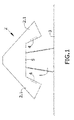
- Figure 1 shows the weapon marking reader where it can be seen that the reader is generally T-shaped from a frontal view, comprising a vertical support (1) on the upper end of which there is an inverted U-shaped upper structure (2) with diverging sides or sloping flaps (2.1), inside which spotlights (4) are housed, whereas at the bottom of the upper structure (2) a camera (5) is arranged.
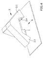
- the sloping flaps (2.1) of the upper structure (2) have a slope such that the projection of the light radiated by the spotlights (4) is concentrated in a central area (6) ( Figures 3 and 4 ).
- the assembly is fixed and supported on a base (3) by means of the vertical support (3).
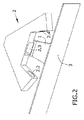
- Figure 2 shows the upper structure (2) of the reader and the cavities made thereon, having cavities (2.2) in the inner faces of the sloping flaps (2.1) where the spotlights (4) are housed ( Figure 1 ), whereas there is a cavity (2.3) at the bottom of the inverted U shape of the upper structure where the camera (5) is housed.
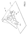
- Figure 3 shows the inside of the upper structure (2) of the reader, pointing out how a central space (6) is defined between the base (3) and the upper structure (2) where the illumination from the spotlights (4) converges with the recording area of the camera (5).
- Said central space (6) is for placing the part of the weapon containing the marking to be read by means of a camera (5) located at a distance such that it allows capturing the image of the marking.
- the camera has a resolution of at least 1280X1024 with a minimum sensor size of 1:8" and an optic thereof of 6 and 12 mm. To enable assuring a size of 64 pixels high in the character of the marking to be read, the camera is located at most 23 cm from the image to be captured.
- the spotlights used (4) can be LED-type spotlights, which, despite their low consumption, sufficiently light up the area where the camera can read the marked surfaces. This is done with two spotlights of at least 290 lumens.
- the structure furthermore means that the angle of incidence of the light emitted by the spotlights on the weapon is the best angle of incidence for most weapon types.
- the most suitable projection angle is around 65° with respect to the horizontal, calculated so as to optimize functionality, the light satisfactorily highlights most markings, regardless of the type of marking and especially regardless of the surface on which said marking is located, and regardless of the finish, material, color, curvature, shine, reflection, etc., making them readily visible, legible and interpretable.
- said base of the reader does not reflect the light
- said base is lined with a ribbed, non-reflective black plastic material minimizing shine and reflections in areas that are not of interest as they are not part of the weapon.
Landscapes
- Engineering & Computer Science (AREA)
- General Engineering & Computer Science (AREA)
- Physics & Mathematics (AREA)
- General Physics & Mathematics (AREA)
- Aiming, Guidance, Guns With A Light Source, Armor, Camouflage, And Targets (AREA)
Priority Applications (1)
| Application Number | Priority Date | Filing Date | Title |
|---|---|---|---|
| EP14382068.6A EP2913623A1 (de) | 2014-02-27 | 2014-02-27 | Leser für Waffenbeschriftung |
Applications Claiming Priority (1)
| Application Number | Priority Date | Filing Date | Title |
|---|---|---|---|
| EP14382068.6A EP2913623A1 (de) | 2014-02-27 | 2014-02-27 | Leser für Waffenbeschriftung |
Publications (1)
| Publication Number | Publication Date |
|---|---|
| EP2913623A1 true EP2913623A1 (de) | 2015-09-02 |
Family
ID=50280335
Family Applications (1)
| Application Number | Title | Priority Date | Filing Date |
|---|---|---|---|
| EP14382068.6A Withdrawn EP2913623A1 (de) | 2014-02-27 | 2014-02-27 | Leser für Waffenbeschriftung |
Country Status (1)
| Country | Link |
|---|---|
| EP (1) | EP2913623A1 (de) |
Cited By (1)
| Publication number | Priority date | Publication date | Assignee | Title |
|---|---|---|---|---|
| CN114506460A (zh) * | 2022-03-15 | 2022-05-17 | 中国商用飞机有限责任公司 | 用于监测襟翼故障的系统及方法 |
Citations (11)
| Publication number | Priority date | Publication date | Assignee | Title |
|---|---|---|---|---|
| WO1992015010A1 (en) * | 1991-02-20 | 1992-09-03 | Pressco Technology, Inc. | Engineered lighting system for tdi inspection |
| WO1999022224A1 (en) * | 1997-10-29 | 1999-05-06 | Vista Computer Vision Ltd. | Illumination system for object inspection |
| EP0974924A2 (de) * | 1998-07-24 | 2000-01-26 | Eastman Kodak Company | Datenlesevorrichtung und Lesesystem mit sichtbaren zenterlosen Zielen |
| US7068808B1 (en) * | 1998-06-10 | 2006-06-27 | Prokoski Francine J | Method and apparatus for alignment, comparison and identification of characteristic tool marks, including ballistic signatures |
| EP1688861A2 (de) * | 2005-02-07 | 2006-08-09 | Sick Ag | Codeleser |
| US20080137323A1 (en) * | 2006-09-29 | 2008-06-12 | Pastore Timothy M | Methods for camera-based inspections |
| US20080137324A1 (en) * | 2006-09-29 | 2008-06-12 | Pastore Timothy M | Systems and/or devices for providing diffuse light |
| US20080137325A1 (en) * | 2006-09-29 | 2008-06-12 | Pastore Timothy M | Methods for providing diffuse light |
| US20100103661A1 (en) * | 2008-10-27 | 2010-04-29 | Yih-Chih Chiou | Machine Vision Inspection System and Light Source Module thereof |
| US7822263B1 (en) * | 2005-12-28 | 2010-10-26 | Prokoski Francine J | Method and apparatus for alignment, comparison and identification of characteristic tool marks, including ballistic signatures |
| US20140028867A1 (en) * | 2012-07-25 | 2014-01-30 | Douglas Alan Erickson | Illuminating Device for Close-up Photographing |
-
2014
- 2014-02-27 EP EP14382068.6A patent/EP2913623A1/de not_active Withdrawn
Patent Citations (11)
| Publication number | Priority date | Publication date | Assignee | Title |
|---|---|---|---|---|
| WO1992015010A1 (en) * | 1991-02-20 | 1992-09-03 | Pressco Technology, Inc. | Engineered lighting system for tdi inspection |
| WO1999022224A1 (en) * | 1997-10-29 | 1999-05-06 | Vista Computer Vision Ltd. | Illumination system for object inspection |
| US7068808B1 (en) * | 1998-06-10 | 2006-06-27 | Prokoski Francine J | Method and apparatus for alignment, comparison and identification of characteristic tool marks, including ballistic signatures |
| EP0974924A2 (de) * | 1998-07-24 | 2000-01-26 | Eastman Kodak Company | Datenlesevorrichtung und Lesesystem mit sichtbaren zenterlosen Zielen |
| EP1688861A2 (de) * | 2005-02-07 | 2006-08-09 | Sick Ag | Codeleser |
| US7822263B1 (en) * | 2005-12-28 | 2010-10-26 | Prokoski Francine J | Method and apparatus for alignment, comparison and identification of characteristic tool marks, including ballistic signatures |
| US20080137323A1 (en) * | 2006-09-29 | 2008-06-12 | Pastore Timothy M | Methods for camera-based inspections |
| US20080137324A1 (en) * | 2006-09-29 | 2008-06-12 | Pastore Timothy M | Systems and/or devices for providing diffuse light |
| US20080137325A1 (en) * | 2006-09-29 | 2008-06-12 | Pastore Timothy M | Methods for providing diffuse light |
| US20100103661A1 (en) * | 2008-10-27 | 2010-04-29 | Yih-Chih Chiou | Machine Vision Inspection System and Light Source Module thereof |
| US20140028867A1 (en) * | 2012-07-25 | 2014-01-30 | Douglas Alan Erickson | Illuminating Device for Close-up Photographing |
Cited By (2)
| Publication number | Priority date | Publication date | Assignee | Title |
|---|---|---|---|---|
| CN114506460A (zh) * | 2022-03-15 | 2022-05-17 | 中国商用飞机有限责任公司 | 用于监测襟翼故障的系统及方法 |
| CN114506460B (zh) * | 2022-03-15 | 2024-05-10 | 中国商用飞机有限责任公司 | 用于监测襟翼故障的系统及方法 |
Similar Documents
| Publication | Publication Date | Title |
|---|---|---|
| US10715712B2 (en) | Barcode readers and component arrangements thereof | |
| US10791276B2 (en) | Automated local positioning system calibration using optically readable markers | |
| US20150269403A1 (en) | Barcode reader having multiple sets of imaging optics | |
| KR101932152B1 (ko) | 촬상 판독기 내부에 미리 결정된 각도 관계로 인쇄 회로 기판을 지지하기 위한 촬상 모듈, 및 조립 방법 | |
| EP2856409B1 (de) | Produktechtheitsprüfvorrichtung mit einer eingebauten lichtemittierenden vorrichtung und einer kamera | |
| ATE405808T1 (de) | Zieleinrichtung für eine schusswaffe | |
| US20120167439A1 (en) | System, method and computer program product for aiming target | |
| EP3081926B1 (de) | System und verfahren zur erfassung von bildern einer oberflächentextur | |
| KR102134751B1 (ko) | 정자 간이 검사 키트, 시스템 및 정자의 간이 검사 방법 | |
| US10623541B2 (en) | External device and mounting structure for mounting to electronic device | |
| AU2017204329B2 (en) | Imaging module and reader for, and method of, reading a target over a field of view by image capture with a visually prominent indicator of a center zone of the field of view | |
| US10628646B1 (en) | Off-axis dual-sensor vision system camera and method for using the same | |
| ES2968246T3 (es) | Método de autenticación de documentos por medio de un terminal móvil de telecomunicaciones | |
| FI3891711T3 (fi) | Menetelmä liekinilmaisimen optista kohdistamista ja näkökentän eheyden tarkistamista varten sekä järjestelmä | |
| TW201725065A (zh) | 自動計分鏢靶裝置及其飛鏢自動計分方法 | |
| US20180270460A1 (en) | Projector system | |
| US9267762B2 (en) | System and method for marksmanship training | |
| EP2891920B1 (de) | Lichtverstärkende Komponente und fotografische Vorrichtung damit | |
| EP2913623A1 (de) | Leser für Waffenbeschriftung | |
| EP1996976B1 (de) | Kamerabeleuchtung für ein elektronisches vergrösserungsglas | |
| LT6979B (lt) | Ginklo kulkos kritimo ir atstumo nustatymo sistema | |
| US20110141345A1 (en) | Projected Light Scale for Forensic Photography | |
| JP2015008374A (ja) | 携帯端末、撮影方法及びプログラム | |
| EP3688401B1 (de) | Wärmevisiere | |
| JP2013106238A (ja) | マーカの検出および追跡装置 |
Legal Events
| Date | Code | Title | Description |
|---|---|---|---|
| PUAI | Public reference made under article 153(3) epc to a published international application that has entered the european phase |
Free format text: ORIGINAL CODE: 0009012 |
|
| AK | Designated contracting states |
Kind code of ref document: A1 Designated state(s): AL AT BE BG CH CY CZ DE DK EE ES FI FR GB GR HR HU IE IS IT LI LT LU LV MC MK MT NL NO PL PT RO RS SE SI SK SM TR |
|
| AX | Request for extension of the european patent |
Extension state: BA ME |
|
| STAA | Information on the status of an ep patent application or granted ep patent |
Free format text: STATUS: THE APPLICATION IS DEEMED TO BE WITHDRAWN |
|
| 18D | Application deemed to be withdrawn |
Effective date: 20160303 |