EP1688106A2 - Orthopedic device for correcting abnormal positions of toes - Google Patents
Orthopedic device for correcting abnormal positions of toes Download PDFInfo
- Publication number
- EP1688106A2 EP1688106A2 EP06008529A EP06008529A EP1688106A2 EP 1688106 A2 EP1688106 A2 EP 1688106A2 EP 06008529 A EP06008529 A EP 06008529A EP 06008529 A EP06008529 A EP 06008529A EP 1688106 A2 EP1688106 A2 EP 1688106A2
- Authority
- EP
- European Patent Office
- Prior art keywords
- hinge
- joint
- rail
- foot
- ring
- Prior art date
- Legal status (The legal status is an assumption and is not a legal conclusion. Google has not performed a legal analysis and makes no representation as to the accuracy of the status listed.)
- Granted
Links
Images


Classifications
-
- A—HUMAN NECESSITIES
- A61—MEDICAL OR VETERINARY SCIENCE; HYGIENE
- A61F—FILTERS IMPLANTABLE INTO BLOOD VESSELS; PROSTHESES; DEVICES PROVIDING PATENCY TO, OR PREVENTING COLLAPSING OF, TUBULAR STRUCTURES OF THE BODY, e.g. STENTS; ORTHOPAEDIC, NURSING OR CONTRACEPTIVE DEVICES; FOMENTATION; TREATMENT OR PROTECTION OF EYES OR EARS; BANDAGES, DRESSINGS OR ABSORBENT PADS; FIRST-AID KITS
- A61F5/00—Orthopaedic methods or devices for non-surgical treatment of bones or joints; Nursing devices; Anti-rape devices
- A61F5/01—Orthopaedic devices, e.g. splints, casts or braces
- A61F5/10—Devices for correcting deformities of the fingers
-
- A—HUMAN NECESSITIES
- A61—MEDICAL OR VETERINARY SCIENCE; HYGIENE
- A61F—FILTERS IMPLANTABLE INTO BLOOD VESSELS; PROSTHESES; DEVICES PROVIDING PATENCY TO, OR PREVENTING COLLAPSING OF, TUBULAR STRUCTURES OF THE BODY, e.g. STENTS; ORTHOPAEDIC, NURSING OR CONTRACEPTIVE DEVICES; FOMENTATION; TREATMENT OR PROTECTION OF EYES OR EARS; BANDAGES, DRESSINGS OR ABSORBENT PADS; FIRST-AID KITS
- A61F5/00—Orthopaedic methods or devices for non-surgical treatment of bones or joints; Nursing devices; Anti-rape devices
- A61F5/01—Orthopaedic devices, e.g. splints, casts or braces
- A61F5/0102—Orthopaedic devices, e.g. splints, casts or braces specially adapted for correcting deformities of the limbs or for supporting them; Ortheses, e.g. with articulations
-
- A—HUMAN NECESSITIES
- A61—MEDICAL OR VETERINARY SCIENCE; HYGIENE
- A61F—FILTERS IMPLANTABLE INTO BLOOD VESSELS; PROSTHESES; DEVICES PROVIDING PATENCY TO, OR PREVENTING COLLAPSING OF, TUBULAR STRUCTURES OF THE BODY, e.g. STENTS; ORTHOPAEDIC, NURSING OR CONTRACEPTIVE DEVICES; FOMENTATION; TREATMENT OR PROTECTION OF EYES OR EARS; BANDAGES, DRESSINGS OR ABSORBENT PADS; FIRST-AID KITS
- A61F5/00—Orthopaedic methods or devices for non-surgical treatment of bones or joints; Nursing devices; Anti-rape devices
- A61F5/01—Orthopaedic devices, e.g. splints, casts or braces
- A61F5/019—Toe correcting or spreading devices
Definitions
- the invention relates to an orthopedic device for correcting toe deformities according to the preamble of claim 1.
- bale rail which acts as a bending spring acting along the inner side of the foot and has at its toe end a ring eyelet, which serves to accommodate the big toe.
- a Ümbiegung At the opposite end of the bale rail has a Ümbiegung, which can be placed around the heel. This allows a big toe to spend from a bent toe misalignment in the normal position.
- This rail has significant disadvantages, for. B. it is perceived by the wearers as extremely uncomfortable in comfort, so that they are very reluctant to create what the treatment success is not guaranteed.
- German Utility Model DE 8 902 545.8 U1 discloses a device for treating big toes which has a stocking with a big toe compartment surrounding the big toe and a rail running along the inside of the foot which is arranged in a pocket sewn onto the socks.
- Such a device for the treatment of big toes is intended for treatment in the night or sleep time.
- the disadvantage is that the freedom of movement of the splintered great toe in the flexion-extension direction of movement of the big toe is prevented.
- This device is thus not suitable for a long-term treatment. Wearing this device in a shoe is very uncomfortable for a patient and severely limits the freedom of movement.
- spreading devices are known, which are designed as a wedge and are arranged in the intermediate space between the big toe and the second toe, so that the big toe is pressed towards the inside of the foot.
- These devices have the disadvantage that they can be supported to exert force on the adjacent toes and thus cause or promote misalignment of the neighboring toes.
- the object of the invention is to provide a device with the valgus malposition of toes, d. H. Malpositions of one or more toes towards the foot outside, can be treated. Furthermore, the device should be portable, in particular portable without significant impairment in everyday life. The treatment success should be improved over the prior art.
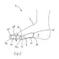
- a first embodiment of the device 1 according to the invention has a sock 2 or the like covering element for the foot which is open in the toe area.
- the sock 2 has an opening which is delimited by a boundary edge 3.
- the device 1 according to the invention has a big toe pick-up, for example a Big toe compartment 4, which is integrally connected to the stocking 2 or attached to this stocking 2.
- the big toe compartment 4 surrounds the big toe circumferentially preferably completely and is designed to be open in the area of the free toe end.
- the big toe compartment 4 is designed to be closed at the front, since this ensures better protection against slippage of the big toe compartment 4 relative to the big toe.
- the device 1 In the area of the metatarsus, the device 1 according to the invention has a first annular bandage 5 which preferably completely surrounds the metatarsus and is expediently connected to the stocking 2.
- the first ring bandage 5 surrounds the stocking 2 in the region of the midfoot on the outside.
- a second annular bandage 6 Surrounding the big toe compartment 4 in the region of the free end of the big toe is a second annular bandage 6, which circumferentially preferably completely surrounds the big toe.
- the ring bandages 5 and 6 are preferably made of a flexible, pliable, circular zugstarren, d. H. Tensile in the circumferential direction, formed material, for example, a fabric tape or a karstarren adhesive tape.
- both the first ring bandage 5 and the second ring bandage 6 is partially not connected to the stocking 2 or the big toe compartment 4, so that between the ring bandages 5, 6 and the big toe compartment 4 and the stocking 2 attachment / receiving devices 8a, 8b, for example, pockets, are formed.
- foot inner side 7 the longitudinal side of a foot is defined, which points to the adjacent foot.
- the outside of the foot is the inner side of the opposite longitudinal side of the foot.
- a bending rail 9 extends along the inside of the foot 7 from the receiving device 8b to the receiving device 8a.
- the bending rail 9 is designed as an articulated bending rail and has a first articulated rail leg 10 and a second articulated rail leg 11, which are pivotably connected about a pivot axis 12 by means of a hinge device 13 are.
- the hinge device 13 is arranged with respect to the sock 2 or the foot such that the pivot axis 12 is approximately at the hinge axis of the big toe joint in the flexion extension direction 20, i. in the natural diffraction direction, ie the dorsal and plantar flexion direction. From the joint device 13, the first joint rail leg 10 extends into the receiving device 8a.
- the joint device 13 in the patient is arranged approximately in the region of a foot-side bulge (pseudoexostosis) typical of the hallux valgus malpositions, which often protrudes beyond the foot circumference contour on the inside of the foot.
- a force F1 which acts in the mediolateral direction towards the inner side of the foot is exerted on it.
- a force F2 is exerted in the opposite direction over the bulge.
- a supporting force F3 resulting from the forces F1 and F2 is received by the first annular bandage 5 in the receiving device 8b.
- a pad 14 in particular a splaying foot pad, is expediently inserted behind the base joints of the toes for retrocapital support of the metatarsus. This causes a supportive erection of the transverse arch, which has a further positive influence on the correction of toe misalignments.
- the device 1 according to the invention consists only of the annular bandages 5, 6, the bending bar 9 and, if necessary, the pad 14, so that the bending bar 9 at least partially rests directly on the patient's skin.
- This simplest embodiment of the device 1 according to the invention has proven to be particularly effective, since an unintentional slipping of the device 1 relative to the patient's foot is prevented precisely by the absence of the stocking interlayer. Thus, by omitting the stocking surprisingly a high level of comfort is realized.
- a device 1 without a stocking represents the most cost-effective embodiment in the production.
- the ring bandages 4, 5 are each connected to the associated joint rail leg 10, 11.
- the receiving devices 8a and 8b are designed as pockets sewn onto the sock 2 or the like.
- the stocking 2 it is expedient to form the stocking 2 as a so-called compression stocking, so that even without the ring bandages 5, 6 a sufficiently large power transmission, d. H. a sufficiently large introduction of the forces F1 and F3 is ensured in the foot.
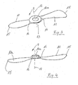
- the hinge device 13 is essentially in three parts from the first joint rail leg 10, the second joint rail leg 11 and a joint rail leg connection device 14a, in particular a hollow rivet constructed.
- the joint rail legs 10, 11 each have a free end 15 and a hinge-side end 16.
- the joint-side ends 16 have approximately a spherical cap shape, which are designed to correspond to one another in such a way that the respective joint-side ends 16 of the joint rail legs 10, 11 are interengageable in a form-fitting manner. From the spherical cap-shaped joint-side ends 16, which are connected by means of the rivet 14a, the hinge device 13 is formed, which has a high stability in the mediolateral direction by the spherical cap-shaped configuration of the joint-side ends 16.
- the bulging of the joint device 13 is advantageous by the bulging of the joint device 13 as a combinatorial effect that in this way an individual adaptation of the joint device 14a to the foot contour of the patient in the area of the big toe joint is possible in a simple manner.
- This is particularly advantageous since, in the region of the metatarsophalangeal joint, in the presence of a hallux valgus malposition, bulging bulges (that is to say a so-called pseudoexostosis) are often present on the foot.
- the calotte shape, depth, size and the diameter of the calotte are individually matched to the patient's foot.
- the joint rail legs 10, 11, which extend away from the joint device 13, are advantageously designed in cross-section or their entire spatial shape adapted to the foot contour.
- For the formation of the joint-side ends 16 of the hinge rail legs 10, 11 are not only spherical cap-shaped spatial forms, but any type of about the axis 12 rotationally symmetrical, mutually corresponding spatial forms, in particular frusto-conical or in cross-section parabolic shape, suitable.
- the material for the bending rail 9 and the joint rail legs 10, 11 is particularly suitable metal or plastic, with a carbon fiber reinforced thin plate has proved to be particularly favorable, since this is easily malleable under heat and after cooling a large spring force at thinner Has material thickness.
- the rigidity of the bending bar 9 in the mediolateral direction is additionally increased by an uneven cross-sectional shape of the legs 10, 11.
- a device 1 according to the invention that on the inside of the foot or on the big toe to be corrected, only a very thin material support is to be attached, so that the device 1 according to the invention can be worn in ordinary footwear without significant impairment.
- the freedom of movement of the big toe is likewise not limited, since in the device 1 according to the invention it is possible to move the toe in the natural flexion extension direction 20 or in this direction its freedom of movement is not restricted (cf. , Thus, this device 1 is particularly suitable for a continuous treatment both during the day and at night, since the patient feels no significant obstruction by the device 1.
- the hinge rail legs 10, 11 are uneven, d. H. for example, bent with constant thickness formed from a plate material, wherein the shape is adapted to the individual foot contour of the patient. Furthermore, it is of course possible, the joint rail legs 10, 11 in their cross-section lens-shaped, in particular such a lenticular form that the material thickness decreases towards the edges of the joint rail legs 10, 11, so that the geometric adjustment of the bending rail 9 is individually further improved to the patient's foot.
- the orthopedic device 1 according to the invention for the correction of misalignments of several adjacent toes is further developed by z. B. depart from the ring bandage 6 to the big toe traction device in the mediolateral direction and act on one or more adjacent toes, which are also surrounded for example by a toe ring bandage.
- the correction force of the bending rail 9 can be transmitted in the mediolateral direction in a simple manner from the big toe on adjacent toes.
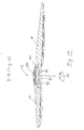
- a further embodiment of the articulated rail 9 of the device 1 according to the invention (FIG. 7) likewise has a first articulated rail leg 10 and a second articulated rail leg 11, which are pivotably connected to one another about a pivot axis 12 by means of a hinge device 13.
- the first joint rail leg 10 is arranged in the case of the arrangement of the device 1 in the region of the big toe of the patient on the inside of the foot.
- the second joint rail leg 11 is arranged in this case in the region of the midfoot of the patient on the inside of the foot.
- the first joint rail leg 10 has an outer side facing away from the foot 50 and an inner side 51 pointing towards the foot.
- the first joint rail leg 10 has a substantially plate-shaped spatial shape curved in the longitudinal and transverse direction, with a first longitudinal boundary edge 52 and a second longitudinal boundary edge 53 and a narrow boundary edge 54. Adjacent to the longitudinal boundary edges 52, 53 extending the hinge rail leg 10 has slot-shaped openings 55, so that a central web 56 and edge webs 57 are formed.
- the bulges of the joint rail leg 10 in its longitudinal and transverse directions are adapted to the anatomical conditions of a foot.
- the annular bandage 6 is provided, which is connected to the joint rail leg 10.
- the ring bandage 6 has a loop body 60 and free ends 61.
- the loop body 60 serves to wrap around the big toe of the patient.
- the free ends 61 are from the inside 51 ago through the slot-shaped openings 55, this by cross, guided, and the edge webs 57 releasably secured to an outer side of the loop body 60.
- this has a joint ring 70, whose center axis is the pivot axis 12.
- the joint ring 70 is preferably integrally connected to the first joint rail leg 10.
- the joint ring 70 has an outer side 71, an inner side 72 and a ring step 73 extending from the inner side 72 in the direction of the pivot axis 9.
- the second hinge rail leg 11 has an outer side 80 and an inner side 81 and a first longitudinal boundary edge 82 and a second longitudinal boundary edge 83 and a narrow side boundary edge 84.
- the second hinge rail leg 11 is constructed in terms of its spatial shape substantially as a longitudinally and transversely curved plate-shaped body, the Volumes in the longitudinal and transverse directions are adapted to the anatomical conditions in the area of the metatarsus on an inner side of the foot.
- the second joint rail leg 11, as well as the first joint rail leg 10 are each tapered in material thickness, so that, for example, FIG. B. is formed in a cross-section approximately lenticular Räumform.
- the second hinge rail legs 11 slot-shaped openings 85, so that a central web 86 and edge webs 87 and between the edge webs, 87 and the middle web 86 arranged intermediate webs 88 are formed.
- the joint-side end 16 of the second joint rail leg 11 is preferably integrally connected to the joint rail leg 11 and is designed as a hinge plate 90 which forms the hinge device 13 with the joint ring 70 of the first joint rail leg 10.
- the hinge plate 90 faces the foot skin and rests on it.
- the hinge ring 70 is set outside against the hinge plate 90.
- the hinge plate 90 has concentric with the ring opening of the hinge ring 7 on an annular ridge 91, which extends from the hinge plate 90 a piece in the direction of the interior of the hinge ring 70.
- the annular web 91 is seated without clearance or almost free of play within the annular step 73 of the hinge ring 70, so that a radial guidance of the hinge plate 90 and the hinge ring 70 is ensured to each other.
- Ravynasensegmente 92 ( Figure 9) are integrally formed on the ring land 91, which cooperate with an upper surface of the annular step 73 and thus ensure an axial fixing of the joint rail legs 10 and 11 to each other.
- the arrangement of the latching nose segments 92 will be described in more detail in connection with FIG. 9.
- the hinge plate 90 has a dome-shaped in cross section, in particular spherical cap-shaped spatial form and has a side facing the foot 93 and a hinged to the hinge ring 94 outside 94, which is corresponding to the inside 93 also, in particular in the area outside the ring land 91, dome-shaped or partially formed dome-shaped.
- the hinge ring 70 on one of the outside 71 opposite inner side 75 which is formed in its spatial form such that it rests flat on the corresponding inner side 93 of the hinge plate 90 in the region outside the annular web 91.
- the annular web 91 has at its free end a further latching ring 96 or latching ring segments which serve for fastening a cover-like closure device 100 (cf. FIGS. 8, 10).
- the cover-like closure device 100 has counter-latching means 101 corresponding to the latching web 96, so that the closure device can be positively connected to the hinge plate 90 or its annular web 91.
- the closure device 100 has an outer side 102, which is formed in its spatial form such that a harmonious transition from the upper side 73 of the joint ring 70 is ensured.
- the closure device 100 serves to close the open joint device and thus to protect against contamination and / or damage.
- the closure device 100 is inserted with play to the inside 72 of the hinge ring to avoid unwanted noise and / or excessive friction.
- an easy-to-install hinge device 13 is created, which has an extremely high bending load capacity with low material thickness and also manages with only a few components.
- the formation of the joint device 13 in the manner of a ring joint that in the joint device 13 high bending forces and bending moments can be introduced without affecting their ease or to promote their excessive wear. This is mainly due to the large span, which is made possible by an outside engagement of the Rastnasensegmente 92 in an inner side annular step 72 of the hinge ring 70.
- the hinge rail 9 is formed essentially of only two individual parts, which ensure the function of the rail 9.
- the closure device 100 has only a closure function and is not necessary for the formation of the joint.
- Particularly advantageous in such an embodiment of the joint device 13 is that in the region of the metatarsophalangeal joint against a possibly existing pseudoexostosis of the patient's foot inside 93 of the hinge plate 90 has a smooth surface, ie no protruding or protruding portions or edges, which significantly increases the comfort .
- the dome-shaped configuration the greatest possible pressure relief of sensitive areas of the foot (pseudoexostosis) and thus a pain relief of the patient is ensured, since the initiated pressure force F 2 is distributed over a large area.
- the inside 51, the inside 93 and the inside 81 of the joint rail components 10, 11 have a steady, stepless and smooth course, so that the wearing comfort on the foot is further improved.
- the slot-shaped openings 55 and 85 have toothings 55a on their flank surfaces which constitute a slip-resistance for the annular bandages 6 to be threaded through.
- the joint rail legs 10 and 11 close in their longitudinal extent with the pivot axis 12 at an angle ⁇ or ⁇ (see FIG. 11).
- the angles ⁇ and ⁇ are chosen such that the joint rail 9 can be applied to a patient's foot so that the pivot axis 12 is approximately aligned with the anatomical joint axis of the big toe joint, so that upon pivotal movement of the joint with the joint rail legs 10 and 11 attached to the foot Kinematically largely adapted to the anatomical conditions of the great toe joint pivotal movement of the hinge rail 9 is made possible.
- the angles .alpha. And .beta are chosen such that the joint rail 9 can be applied to a patient's foot so that the pivot axis 12 is approximately aligned with the anatomical joint axis of the big toe joint, so that upon pivotal movement of the joint with the joint rail legs 10 and 11 attached to the foot Kinematically largely adapted to the anatomical conditions of the great toe joint pivotal movement of the hinge rail 9 is
- angles ⁇ and ⁇ are selected in such a way that a correction for a orthopedic normal position can be achieved for a big toe (hallux valgus position) which is tilted to the foot outside.
- hallux valgus position hallux valgus position
- the selection of the angles ⁇ and ⁇ according to the above criteria is of course possible for all outlined in this application embodiments and not limited to the embodiment of FIGS. 7 to 11.
- the desired correction force has a range between 75 ° and 115 ° for the angle ⁇ proven. Within this range, a large part of the occurring hallux valgus and hallux varus inclinations can be corrected. Of course, in extreme individual cases, an angle ⁇ outside this range may be necessary. For the angle ⁇ has an angle of about 70 ° to 110 ° proven to correct most of the commonly occurring hallux valgus and / or hallux varus positions. Of course, too for the angle ⁇ , that in individual cases it can be chosen larger or smaller.
- FIG. 12 A further embodiment of the hinge rail 9 of the device 1 according to the invention (FIG. 12) is constructed essentially identically to the embodiment according to FIGS. 7 and is based on the same active principle with regard to the correction of the toe misalignments.
- the joint device 13 In contrast to the embodiment according to FIGS. 7 to 11, in the embodiment according to FIGS. 12 to 17, only the joint device 13 is configured somewhat differently.
- the inner side 72 of the hinge ring 70 is slightly larger in its axial longitudinal extent.
- the annular web 91 of the hinge plate 90 has only the Rastnasensegmente 92, but not on the patch Rastnasensege segments 96 for holding the closure device 100th
- the closure device 100 (cf. FIG. 13) is inserted into the joint ring 70 in such a way that an outer ring wall 105 of the closure device 100 interacts with the inner side 72 of the joint ring 70 in such a way that the closure device 100 is secured by means of a clamping seat, possibly also by means of a glued seat Joint ring 70 is attached.
- a clamping seat possibly also by means of a glued seat Joint ring 70 is attached.
- the hinge surfaces 94 of the hinge plate 90 and the corresponding surface 75 of the hinge ring 70 are formed as planar annular surfaces, which simplifies design to the effect that the radial guidance of the hinge ring 70 with respect to the hinge plate 90 takes place exclusively via an outer side 91a of the annular web 91 and via an inner side 73a of the annular step 73.
- FIG. 17 The embodiment of the joint rail 9 according to FIGS. 12 and 13 with an inserted closure device 100 is shown in the longitudinal sectional illustration according to FIG. 17.
- a further embodiment of the hinge device 13 (FIG. 18) of the hinge rail 9 of the device 1 according to the invention is likewise constructed as a so-called annular disc joint with a hinge plate 90 and a hinge ring 70.
- the hinge plate 90 has an inner surface 93 facing the foot skin and an opposite outer side 94. From the outer side 94, a piece extends in the direction away from the foot of the patient, an annular ridge 91, which has a Ringstegau touch Structure 91 a.
- the annular web outer surface 91a serves for the radial guidance of the joint ring 70 and cooperates with or without play with a joint ring inner side 73a.
- the hinge plate 90 is preferably calotte-shaped, in particular spherical-cap-shaped, and has outside of the annular web 91 a partial region of the outer side 94 which serves as a joint sliding surface and cooperates with a corresponding joint sliding surface 78 of the joint ring 70.
- the Gelenkgleit vom have a Kalottenabitess-shaped spatial form.
- the height of the annular step 73 of the joint ring 70 is selected such that an upper side 73b of the annular step terminates flush with a top side 91b of the annular web 91 or projects slightly beyond it.
- a radial guidance of the joint rail legs 10, 11 is ensured by the interaction of the annular webs 91 and the hinge ring 70 with their surfaces 91a and 73a.
- the axial fixing of the hinge rail legs 10, 11 and the hinge ring relative to the hinge plate 90 is ensured as follows.
- the closure device 100 is developed in addition to its closure function of the hinge device 13 as a thrust bearing.
- the closure device 100 has a closure device body 103 which, as in the above-described embodiments, essentially covers the joint device 13 and thus protects it against soiling. From the closure device body 103, opposite the top side 102, there extends an annular web 105, which is dimensioned in diameter such that it can be inserted inside the annular web 91 of the hinge plate 90 in the space bounded by the annular web 91.
- the closure device 100 has a circumferential projection 106 which is dimensioned in the radial direction such that it projects radially beyond the annular web 91 and rests on the annular step top side 73b of the annular step without play or with little axial play.
- an underside 107 of the annular projection 106 which cooperates with the upper side 73b of the annular step 73, serves as an axial abutment.
- the closure device 100 is expediently adhesively bonded or otherwise securely fastened to the hinge plate or its annular web 91 at one or more of its contact surfaces.
- this hinge device 9 has the particular advantage that the most sensitive areas of the foot adjacent surfaces 93, z. B. in the area of a pseudoexostosis, are smooth, ie that no supernatants or depressions irritate the local skin areas.
- the joint design according to FIG. 18 has a particularly high flexural rigidity and can not be readily dismantled even by abusive overstretching of the splint, ie, that due to improper treatment by the patient, e.g. B. by twisting, bending over or the like, it is excluded that the two joint rail legs 10, 11 are separable from each other.
- an impact-resistant and skin-friendly plastic z. B. from the group of polycarbonates, proven.
- the annular bandage 6 in the area of the big toe serves as a fastening device and has the loop body 60 as well as free ends 61.
- the loop body 60 together with the first hinge rail leg 10, defines an interior space 62 in which the toe of the patient is arranged.
- the free ends 61 are guided from the inner side 51 through the slot-shaped openings 55 and around the edge web 57, this surrounding, wrapped around.
- the free end 61 of the annular bandage 6 adjacent to the hinge rail leg 10 comes outside with the loop body 60 to the plant.
- the free end 61 is suitably releasably secured by means of a hook and loop fastener 63 on the outside of the loop body.
- This type of attachment of the free end 61 can be on both free ends 61 of the ring bandage 6 are applied. However, it may be useful to beat a free end 61 around an edge web 57 and, if necessary, to firmly sew it with the loop body 60 and to connect only another free end 61 to the loop body 60 by means of a Velcro connection or the like.
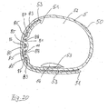
- the ring bandage 5 serves as a fastening device and as a bandage for supporting and rebuilding the transverse arch of the foot and is also connected to a loop body 50 forming the second joint rail leg 11.
- the ring bandage 5 also has free ends 51.
- a free end 51 is guided from the inside 81 through the first slot-shaped opening 85 near the bottom of the foot and penetrates them, lies outside on the first intermediate web 88 and penetrates the second slot opening 85 from the outside 80 ago, lies in the region of the central web 86th on the inside 81 and penetrates the next slot-shaped opening 85 from the inside 81 toward the outside, on the second gutter 88 on the outside and penetrates the last slot opening 85 from the outside 80 forth inwards.
- the protruding free end 51 is arranged, for example, in the region of the instep of the foot.
- the remainder of the annular bandage 5, which is not involved in the threading by the second articular track leg 11, guides the patient's foot around the foot bottom and foot top, overlaps the second articular rail leg 11 in the area of the slot openings 85, and is free in the second End 51 attached to the outside of the loop body 50.
- Velcro fasteners in particular hook-and-loop fasteners or mushroom hook and loop fasteners 53, have proven to be suitable as fastening means.
- the pad 14 is expediently also connected to the annular bandage 5 via hook and loop connection elements 53 in the region of the underside of the foot of the patient.
- a further embodiment of the threading of the annular bandage 5 by the second joint rail leg 11 takes place in such a way that a first free end passes through a slot opening 85 from the inner side 81, encompassing the edge web 87 in the area of the underside of the foot and on the outside at the Loop body in the foot base is connected to this by means of connecting elements 53.
- the other free end 51 is guided in the region of the upper side of the foot 81 from the inside 81 by a randliche slot opening 85, outside abuts the first gutter 88 and penetrates another slot-shaped opening 85 in the direction of the inner side 81, lies inside on the central web 86, wraps around this through a further opening 85 and is on the outside in the direction of the foot top, the hinge rail legs 11 partially overlapping, out.
- the free end 51 can thus be secured by means of closure elements 53 on the outside of the loop body 50.
- the annular bandage guide according to FIG. 21 has the advantage that the free ends are in each case arranged on the outside of the loop body 50, so that there is no step in the amount of material thickness plus the connecting elements 51 towards the foot and thus pressure points on the foot are avoided. Also in this embodiment, it is of course possible to guide the fußober workede free end only by a randliche slot opening 85, so that this surrounds the edge web 87 and the outside can be attached to the loop body 50. In this case, the threading or wrapping around the ring bandage 5 corresponds to the ring bandage 6 in the region of the big toe. Also, in this embodiment, in the region of the underside of the foot, the pad 14 can be fastened by means of Velcro elements 53 to an inner side of the loop body 50, in particular detachably.
- the non-rigid, floating within the device 1 to the inside of the foot has the advantage that the device 1 can adapt individually to the anatomical boundary conditions, i. e.g. that the pivot axis 12 of the joint rail 9 aligns automatically after the application of the device 1 in alignment with the anatomical joint axis of the great toe joint.
Abstract
Description
Die Erfindung betrifft eine orthopädische Vorrichtung zur Korrektur von Zehenfehlstellungen nach dem Oberbegriff des Anspruchs 1.The invention relates to an orthopedic device for correcting toe deformities according to the preamble of
Aus der DE 100 34 354 A1 ist eine Fußbandage zur Behandlung von Fehlstellungen des Großzehs, beispielsweise von Hallux valgus, bekannt. Sie weist eine in Fußlängsrichtung dehnbare Aufnahmeeinrichtung für den Großzeh auf, welche mit einem freien Ende an einem im Bereich des Mittelfußes angeordnete, diesen umgebende Ringbandage angebunden ist, sodass auf den Großzeh eine redressierende Kraft in Richtung der anatomischen Sollstellung des Zehs wirkt.From DE 100 34 354 A1 a foot bandage for the treatment of malpositions of the big toe, for example of hallux valgus, known. It has a stretchable in Fußlängsrichtung receiving device for the big toe, which is connected to a free end of a arranged in the region of the metatarsus, this surrounding ring bandage, so acting on the big toe a redressierende force in the direction of the anatomical desired position of the toe.
Solche Vorrichtungen werden erfahrungsgemäß nur ungern und unzuverlässig vom Patienten angelegt, weil sie stark auftragen und im normalen Schuhwerk als hinderlich oder nach längerer Tragedauer sogar lästig oder schmerzhaft empfunden werden. Hierdurch ist der Behandlungserfolg bei Anwendung einer derartigen Bandage nicht sichergestellt.Such devices are experience reluctant and unreliable created by the patient because they apply strong and in normal footwear as a hindrance or after prolonged wearing time even annoying or painful. As a result, the treatment success is not ensured when using such a bandage.
Aus der DE 1 881 215 U1 ist eine Ballenschiene bekannt, welche als Biegefeder wirkend entlang der Fußinnenseite verläuft und an ihrem zehenseitigen Ende eine Ringöse aufweist, welche zur Aufnahme des Großzehs dient. Am gegenüberliegenden Ende weist die Ballenschiene eine Ümbiegung auf, welche sich um die Ferse legen lässt. Hierdurch lässt sich eine Großzehe aus einer eingebogenen Zehenfehlstellung in die Normalstellung verbringen. Diese Schiene weist erhebliche Nachteile auf, z. B. wird sie von den Trägern als extrem unbequem im Tragekomfort empfunden, sodass diese nur sehr ungern angelegt wird, was den Behandlungserfolg nicht gewährleistet.'From DE 1 881 215 U1 a bale rail is known which acts as a bending spring acting along the inner side of the foot and has at its toe end a ring eyelet, which serves to accommodate the big toe. At the opposite end of the bale rail has a Ümbiegung, which can be placed around the heel. This allows a big toe to spend from a bent toe misalignment in the normal position. This rail has significant disadvantages, for. B. it is perceived by the wearers as extremely uncomfortable in comfort, so that they are very reluctant to create what the treatment success is not guaranteed.
Aus dem deutschen Gebrauchsmuster DE 8 902 545.8 U1 ist eine Vorrichtung zur Behandlung von Großzehen bekannt, welche einen Strumpf mit einem den Großzehen umgebenden Großzehenfach aufweist und eine entlang der Fußinnenseite verlaufende Schiene aufweist, welche in einer auf den Socken aufgenähten Tasche angeordnet ist. Eine derartige Vorrichtung zur Behandlung von Großzehen ist zur Behandlung in der Nacht- bzw. Schlafzeit gedacht. Nachteilig ist, dass die Bewegungsfreiheit der geschienten Großzehe in der Flexion-Extension-Bewegungsrichtung des Großzehs unterbunden ist. Diese Vorrichtung eignet sich somit nicht für eine Dauerbehandlung. Ein Tragen dieser Vorrichtung in einem Schuh ist für einen Patienten sehr unangenehm und schränkt die Bewegungsfreiheit stark ein.German Utility Model DE 8 902 545.8 U1 discloses a device for treating big toes which has a stocking with a big toe compartment surrounding the big toe and a rail running along the inside of the foot which is arranged in a pocket sewn onto the socks. Such a device for the treatment of big toes is intended for treatment in the night or sleep time. The disadvantage is that the freedom of movement of the splintered great toe in the flexion-extension direction of movement of the big toe is prevented. This device is thus not suitable for a long-term treatment. Wearing this device in a shoe is very uncomfortable for a patient and severely limits the freedom of movement.
Weiterhin sind Spreizvorrichtungen bekannt, die als Keil ausgebildet sind und im Zwischenraum zwischen dem Großzeh und dem zweiten Zeh angeordnet sind, sodass der Großzeh zur Fußinnenseite hin gedrückt wird. Diese Vorrichtungen haben den Nachteil, dass sie sich zur Kraftausübung an den benachbarten Zehen abstützen und somit eine Fehlstellung der Nachbarzehen verursachen oder fördern können.Furthermore, spreading devices are known, which are designed as a wedge and are arranged in the intermediate space between the big toe and the second toe, so that the big toe is pressed towards the inside of the foot. These devices have the disadvantage that they can be supported to exert force on the adjacent toes and thus cause or promote misalignment of the neighboring toes.
Aufgabe der Erfindung ist es, eine Vorrichtung zu schaffen, mit der Valgus-Fehlstellungen von Zehen, d. h. Fehlstellungen von einer oder mehreren Zehen zur Fußaußenseite hin, behandelt werden können. Weiterhin soll die Vorrichtung angenehm tragbar, insbesondere ohne nennenswerte Beeinträchtigung im Alltag tragbar sein. Der Behandlungserfolg soll gegenüber dem Stand der Technik verbessert werden.The object of the invention is to provide a device with the valgus malposition of toes, d. H. Malpositions of one or more toes towards the foot outside, can be treated. Furthermore, the device should be portable, in particular portable without significant impairment in everyday life. The treatment success should be improved over the prior art.
Diese Aufgabe wird mit einer orthopädischen Vorrichtung zur Korrektur von Zehenfehlstellungen mit den Merkmalen des Anspruchs 1 gelöst. Vorteilhafte Weiterbildungen der Erfindung sind in den Unteransprüchen angegeben.This object is achieved with an orthopedic device for correcting toe deformities with the features of
Im Folgenden wird die Erfindung anhand der Zeichnungen beispielhaft näher erläutert. Es zeigen:
- Fig. 1
- schematisch eine Unteransicht auf eine erste erfindungsgemäße Vorrichtung;
- Fig. 1a
- schematisch eine Unteransicht auf eine zweite besonders bevorzugte Ausführungsform der erfindungsgemäßen Vorrichtung;
- Fig. 2
- schematisch die erfindungsgemäße Vorrichtung gem. Fig. 1 in einer Ansicht auf die Fußinnenseite;
- Fig. 3
- schematisch eine Gelenkschiene der erfindungsgemäßen Vorrichtung in einer perspektivischen Detailansicht;
- Fig. 4
- schematisch die Gelenkschiene aus Fig. 3 in einer Draufsicht;
- Fig. 5
- schematisch eine Ausschnittsansicht auf einen Vorderfußbereich (Zehe und Mittelfuß) einer dritten Ausführungsform einer erfindungsgemäßen Vorrichtung in einer gestreckten Stellung;
- Fig. 6
- schematisch eine Ausschnittsansicht auf einen Vorderfußbereich (Zehe und Mittelfuß) der dritten Ausführungsform einer erfindungsgemäßen Vorrichtung in einer abgewinkelten Stellung;
- Fig. 7
- eine perspektivische Ansicht einer weiteren Ausführungsform der Gelenkschiene der erfindungsgemäßen Vorrichtung;
- Fig. 8
- die Gelenkschiene gemäß Fig. 7 mit einer abgedeckten Gelenkeinrichtung;
- Fig. 9
- einen Querschnitt durch die Gelenkeinrichtung der Gelenkschiene gemäß Fig. 7, entlang der Linie A-A in Fig. 7;
- Fig. 10
- einen Querschnitt durch die Gelenkeinrichtung der Gelenkschiene gemäß Fig. 8 entlang der Linie A-A in Fig. 8;
- Fig. 11
- einen Längsschnitt durch die Gelenkschiene gemäß Fig. 8 entlang der Linie B-B in Fig. 8;
- Fig. 12
- eine perspektivische Darstellung einer weiteren Ausführungsform der Gelenkschiene der erfindungsgemäßen Vorrichtung;
- Fig. 13
- eine perspektivische Darstellung der Gelenkschiene gemäß Fig. 12 mit einer abgedeckten Gelenkeinrichtung;
- Fig. 14
- einen Querschnitt durch die Gelenkeinrichtung der Gelenkschiene gemäß Fig. 12 entlang der Linie A-A;
- Fig. 15
- einen'Querschnitt durch die Gelenkeinrichtung der Gelenkschiene gemäß Fig. 13 entlang der Linie A-A;
- Fig. 16
- einen Längsschnitt durch die Gelenkschiene gemäß Fig. 12 entlang der Linie B-B;
- Fig. 17
- einen Längsschnitt durch die Gelenkschiene gemäß Fig. 13 entlang der Linie B-B;
- Fig. 18
- eine weitere Ausführungsform einer Gelenkeinrichtung der Gelenkschiene in einem teilgeschnittenen Längsschnitt;
- Fig. 19
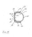
- einen Querschnitt durch einen Gelenkschienenschenkel und eine zugehörige Ringbandage im Bereich des Großzehs;
- Fig. 20
- einen Querschnitt durch einen Gelenkschienenschenkel und eine Ringbandage der erfindungsgemäßen Vorrichtung im Bereich des Mittelfußes;
- Fig. 21
- einen zweiten Querschnitt durch einen Gelenkschienenschenkel und die zugehörige Ringbandage der erfindungsgemäßen Vorrichtung im Bereich des Mittelfußes.
- Fig. 1
- schematically a bottom view of a first device according to the invention;
- Fig. 1a
- schematically a bottom view of a second particularly preferred embodiment of the device according to the invention;
- Fig. 2
- schematically the device according to the invention. Fig. 1 in a view of the foot inside;
- Fig. 3
- schematically a joint rail of the device according to the invention in a perspective detail view;
- Fig. 4
- schematically the hinge rail of Figure 3 in a plan view.
- Fig. 5
- schematically a sectional view of a forefoot (toe and metatarsus) of a third embodiment a device according to the invention in an extended position;
- Fig. 6
- 1 is a schematic sectional view of a forefoot area (toe and metatarsus) of the third embodiment of a device according to the invention in an angled position;
- Fig. 7
- a perspective view of another embodiment of the hinge rail of the device according to the invention;
- Fig. 8
- the hinge rail of Figure 7 with a covered hinge device.
- Fig. 9
- a cross section through the hinge means of the hinge rail of Figure 7, taken along the line AA in Fig. 7.
- Fig. 10
- a cross section through the hinge means of the hinge rail of Figure 8 along the line AA in Fig. 8.
- Fig. 11
- a longitudinal section through the hinge rail of Figure 8 along the line BB in Fig. 8.
- Fig. 12
- a perspective view of another embodiment of the hinge rail of the device according to the invention;
- Fig. 13
- a perspective view of the hinge rail of Figure 12 with a covered hinge device.
- Fig. 14
- a cross section through the hinge means of the hinge rail of Figure 12 along the line AA.
- Fig. 15
- eine'Querschnitt through the hinge means of the hinge rail of Figure 13 along the line AA.
- Fig. 16
- a longitudinal section through the hinge rail of Figure 12 along the line BB.
- Fig. 17
- a longitudinal section through the hinge rail of Figure 13 along the line BB.
- Fig. 18
- a further embodiment of a hinge device of the joint rail in a partially cut longitudinal section;
- Fig. 19
- a cross section through a joint rail leg and an associated ring bandage in the area of the big toe;
- Fig. 20
- a cross section through a joint rail leg and a ring bandage of the device according to the invention in the region of the metatarsus;
- Fig. 21
- a second cross section through a joint rail leg and the associated ring bandage of the device according to the invention in the region of the metatarsus.
Eine erste Ausführungsform der erfindungsgemäßen Vorrichtung 1 (Fig. 1) weist einen im Zehenbereich offenen Strumpf 2 oder dergleichen Umhüllungselement für den Fuß auf. Im Bereich der Zehen weist der Strumpf 2 eine Öffnung auf, welche durch eine Begrenzungskante 3 begrenzt ist. Weiterhin weist die erfindungsgemäße Vorrichtung 1 eine Großzehenaufnahme, z.B. ein Großzehenfach 4 auf, welches mit dem Strumpf 2 einstückig verbunden oder an diesen Strumpf 2 angesetzt ist. Das Großzehenfach 4 umgibt den Großzeh umfänglich vorzugsweise vollständig und ist im Bereich des freien Zehenendes offen ausgestaltet. Bevorzugt ist das Großzehenfach 4 jedoch vorne geschlossen ausgebildet, da dies einen besseren Schutz gegen Verrutschen des Großzehenfachs 4 relativ zum Großzeh gewährleistet.A first embodiment of the
Im Bereich des Mittelfußes weist die erfindungsgemäße Vorrichtung 1 eine erste Ringbandage 5 auf, welche den Mittelfuß vorzugsweise vollständig umgibt und zweckmäßigerweise mit dem Strumpf 2 verbunden ist. Vorteilhafterweise umgibt die erste Ringbandage 5 den Strumpf 2 im Bereich des Mittelfußes außenseitig.In the area of the metatarsus, the
Das Großzehenfach 4 im Bereich des freien Endes der Großzehe umgebend ist eine zweite Ringbandage 6 angeordnet, welche den Großzeh umfänglich bevorzugt vollständig umgibt. Die Ringbandagen 5 und 6 sind vorzugsweise aus einem biegsamen, schmiegsamen, zirkulär zugstarren, d. h. in Umfangsrichtung zugstarren, Material ausgebildet, beispielsweise aus einem Gewebeband oder einem zugstarren Klebeband. Im Bereich einer Fußinnenseite 7 ist sowohl die erste Ringbandage 5 als auch die zweite Ringbandage 6 teilbereichsweise nicht mit dem Strumpf 2 bzw. dem Großzehenfach 4 verbunden, sodass zwischen den Ringbandagen 5, 6 und dem Großzehenfach 4 bzw. dem Strumpf 2 Befestigungs-/Aufnahmeeinrichtungen 8a, 8b, beispielsweise Einstecktaschen, ausgebildet sind.Surrounding the
Als Fußinnenseite 7 ist die Längsseite eines Fußes definiert, welche zum benachbarten Fuß weist. Die Außenseite des Fußes ist die der Innenseite gegenüberliegende Längsseite des Fußes.As foot
Entlang der Fußinnenseite 7 erstreckt sich von der Aufnahmeeinrichtung 8b hin zur Aufnahmeeinrichtung 8a eine Biegeschiene 9. Die Biegeschiene 9 ist als Gelenkbiegeschiene ausgebildet und weist einen ersten Gelenkschienenschenkel 10 und einen zweiten Gelenkschienenschenkel 11 auf, welche um eine Schwenkachse 12 schwenkbar mittels einer Gelenkeinrichtung 13 gelenkig verbunden sind. Die Gelenkeinrichtung 13 ist bezüglich des Strumpfes 2 bzw. des Fußes derart angeordnet, dass die Schwenkachse 12 in etwa der Gelenkachse des Großzehengrundgelenks in der Flexion-Extensionsrichtung 20 , d.h. in der natürlichen Beugerichtung, also der dorsalen und plantaren Beugerichtung entspricht. Von der Gelenkeinrichtung 13 aus erstreckt sich der erste Gelenkschienenschenkel 10 bis in die Aufnahmeeinrichtung 8a. Von der Gelenkeinrichtung 13 aus erstreckt sich der zweite Gelenkschienenschenkel 11 bis in die zweite Aufnahmeeinrichtung 8b. Somit ist die Gelenkeinrichtung 13 beim Patienten in etwa im Bereich einer fußinnenseitigen, für die Hallux-valgus-Fehlstellungen typischen Ausbuchtung (Pseudoexostose) angeordnet, welche oftmals fußinnenseitig über die Sollfußumfangskontur hervorsteht. Somit wird beim Tragen einer erfindungsgemäßen Vorrichtung 1 im Bereich der Großzehe auf diese eine Kraft F1, welche in Mediolateralrichtung hin zur Fußinnenseite wirkt, ausgeübt. Im Bereich des Zehengrundgelenks wird über die Ausbuchtung eine Kraft F2 in entgegengesetzter Richtung ausgeübt. Eine aus den Kräften F1 und F2 resultierende Abstützkraft F3 wird in der Aufnahmeeinrichtung 8b von der ersten Ringbandage 5 aufgenommen.A bending
Im Bereich der Fußsohle ist zweckmäßigerweise hinter den Grundgelenken der Zehen zur retrokapitalen Abstützung des Mittelfußes eine Pelotte 14, insbesondere eine Spreizfußpelotte eingesetzt. Diese bewirkt ein unterstützendes Aufrichten des Quergewölbes, was einen weiteren positiven Einfluss auf die Korrektur der Zehenfehlstellungen hat.In the area of the sole of the foot, a
Bei der ersten Ausführungsform gemäß Fig. 1 mit den Ringbandagen 5, 6 ist auch die Verwendung eines normalen Strumpfes 2 bzw. einer normalen Strumpfstrickung möglich und zweckmäßig, da die zirkular zugstarren Ringbandagen 5, 6 eine ausreichend große Kraftübertragung gewährleisten.In the first embodiment of FIG. 1 with the
In einer einfachst denkbaren besonders bevorzugten Ausführungsform (Fig. 1a) besteht die erfindungsgemäße Vorrichtung 1 lediglich aus den Ringbandagen 5, 6, der Biegeschiene 9 und ggfs. der Pelotte 14, sodass die Biegeschiene 9 zumindest teilweise direkt auf der Fußhaut des Patienten aufliegt. Diese einfachste Ausführungsform der erfindungsgemäßen Vorrichtung 1 hat sich besonders bewährt, da ein unbeabsichtigtes Verrutschen der Vorrichtung 1 relativ zum Fuß des Patienten gerade durch das Fehlen der Strumpfzwischenlage verhindert ist. Somit ist durch das Weglassen des Strumpfes überraschenderweise ein hoher Tragekomfort verwirklicht. Außerdem stellt eine Vorrichtung 1 ohne einen Strumpf die in der Herstellung kostengünstigste Ausführungsform dar. Bei der Ausführungsform gemäß Fig. 1a sind die Ringbandagen 4, 5 jeweils mit dem zugehörigen Gelenkschienenschenkel 10, 11 verbunden.In a most conceivable particularly preferred embodiment (FIG. 1 a), the
Gemäß einer dritten Ausführungsform der erfindungsgemäßen Vorrichtung (Fig. 2, 5, 6) sind die Aufnahmeeinrichtungen 8a und 8b als auf den Strumpf 2 aufgenähte oder dergleichen befestigte Taschen ausgebildet. Bei dieser Ausführungsform ist es zweckmäßig, den Strumpf 2 als so genannten Kompressionsstrumpf auszubilden, damit auch ohne die Ringbandagen 5, 6 eine ausreichend große Kraftübertragung, d. h. eine ausreichend große Einleitung der Kräfte F1 und F3 in den Fuß gewährleistet ist.According to a third embodiment of the device according to the invention (FIGS. 2, 5, 6), the receiving
Die Gelenkeinrichtung 13 ist im Wesentlichen dreiteilig aus dem ersten Gelenkschienenschenkel 10, dem zweiten Gelenkschienenschenkel 11 und einer Gelenkschienenschenkelverbindungseinrichtung 14a, insbesondere einer Hohlniet, aufgebaut. Die Gelenkschienenschenkel 10, 11 weisen jeweils ein freies Ende 15 und ein gelenkseitiges Ende 16 auf. Die gelenkseitigen Enden 16 weisen in etwa eine Kugelkalottenraumform auf, welche zueinander derart korrespondierend ausgebildet sind, dass die jeweils gelenkseitigen Enden 16 der Gelenkschienenschenkel 10, 11 formschlüssig passend ineinanderlegbar sind. Aus den kugelkalottenförmigen gelenkseitigen Enden 16, welche mittels der Hohlniet 14a verbunden sind, ist die Gelenkeinrichtung 13 gebildet, welche durch die kugelkalottenförmige Ausgestaltung der gelenkseitigen Enden 16 eine hohe Stabilität in der Mediolateralrichtung aufweist.The
Weiterhin ist durch die Ausbeulung der Gelenkeinrichtung 13 als kombinatorische Wirkung von Vorteil, dass hierdurch in einfacher Art und Weise eine individuelle Anpassung der Gelenkeinrichtung 14a an die Fußkontur des Patienten im Bereich des Großzehengrundgelenks möglich ist. Dies ist besonders vorteilhaft, da im Bereich des Großzehengrundgelenks bei Vorliegen einer Hallux-valgus-Fehlstellung oftmals ballenförmige Ausbuchtungen (d. h. eine sogenannte Pseudoexostose) am Fuß vorliegen. In besonders bevorzugter Art und Weise ist die Kalottenform, -tiefe, -größe und der Kalottendurchmesser individuell auf den Patientenfuß abgestimmt.Furthermore, it is advantageous by the bulging of the
Die Gelenkschienenschenkel 10, 11, welche sich von der Gelenkeinrichtung 13 weg erstrecken, sind vorteilhafterweise im Querschnitt bzw. ihrer gesamten Raumform an die Fußkontur angepasst ausgebildet. Für die Ausbildung der gelenkseitigen Enden 16 der Gelenkschienenschenkel 10, 11 sind nicht nur kugelkalottenförmige Raumformen, sondern jede Art von um die Achse 12 rotationssymmetrische, zueinander korrespondierende Raumformen, insbesondere kegelstumpfförmige oder im Querschnitt parabelförmige Raumformen, geeignet.The
Als Material für die Biegeschiene 9 bzw. die Gelenkschienenschenkel 10, 11 eignet sich insbesondere Metall oder Kunststoff, wobei sich eine Kohlefaser-verstärkte dünne Platte als besonders günstig erwiesen hat, da diese unter Hitzeeinwirkung leicht formbar ist und nach dem Abkühlen eine große Federkraft bei dünner Materialstärke aufweist. Die Steifigkeit der Biegeschiene 9 in Mediolateralrichtung ist zusätzlich durch eine unebene Querschnittsform der Schenkel 10, 11 erhöht. Somit kann mit einer erfindungsgemäßen Vorrichtung mit einer Biegeschiene 9 zum einen ein hoher Tragekomfort erreicht werden, weil die Biegeschiene 9 individuell an den Fuß des Patienten anpassbar sind, und zum anderen wird hierdurch eine erhöhte Federhärte in Mediolateralrichtung erreicht, sodass im Wesentlichen hieraus resultierend ein überraschenderweise hoher Behandlungserfolg realisiert werden kann.As the material for the bending
Weiterhin ist für eine erfindungsgemäße Vorrichtung 1 gewährleistet, dass an der Fußinnenseite bzw. an der zu korrigierenden Großzehe eine nur sehr dünne Materialauflage anzubringen ist, sodass die erfindungsgemäße Vorrichtung 1 ohne nennenswerte Beeinträchtigung in üblichem Schuhwerk getragen werden kann. Die Bewegungsfreiheit der Großzehe ist dadurch ebenfalls nicht eingeschränkt, da bei der erfindungsgemäßen Vorrichtung 1 die Möglichkeit besteht, die Zehe in der natürlichen Flexion-Extensionsrichtung 20 zu bewegen bzw. in diese Richtung ihre Bewegungsfreiheit nicht eingeschränkt ist (vgl. Fig. 5, 6). Somit eignet sich diese Vorrichtung 1 insbesondere für eine Dauerbehandlung sowohl tags als auch nachts, da der Patient keine nennenswerte Behinderung durch die Vorrichtung 1 verspürt.Furthermore, it is ensured for a
Hinsichtlich ihrer Querschnittsraumform sind die Gelenkschienenschenkel 10, 11 uneben, d. h. beispielsweise gebogen mit konstanter Dicke aus einem Plattenmaterial geformt, wobei die Formgebung an die individuelle Fußkontur des Patienten angepasst ist. Weiterhin ist es selbstverständlich möglich, die Gelenkschienenschenkel 10, 11 in ihrem Querschnitt linsenförmig, insbesondere derart linsenförmig auszubilden, dass die Materialstärke zu den Rändern der Gelenkschienenschenkel 10, 11 hin abnimmt, sodass die geometrische Anpassung der Biegeschiene 9 an den Patientenfuß individuell weiter verbessert ist.With regard to their cross-sectional space shape, the
Gemäß einer weiteren Ausführungsform (nicht gezeigt) ist die erfindungsgemäße orthopädische Vorrichtung 1 zur Korrektur von Fehlstellungen mehrerer benachbarter Zehen weitergebildet, indem z. B. von der Ringbandage 6 um den Großzeh Zugmittel in Mediolateralrichtung abgehen und auf ein oder mehrere benachbarte Zehen einwirken, welche beispielsweise ebenfalls von einer Zehenringbandage umgeben sind. Somit kann die Korrekturkraft der Biegeschiene 9 in Mediolateralrichtung in einfacher Art und Weise vom Großzeh auf benachbarte Zehen übertragen werden. Durch geeignete Wahl der Materialstärke für die Gelenkschienenschenkel 10, 11 sowie durch eine geeignete Wahl eines Umfangsbeschnitts dieser Gelenkschienenschenkel 10, 11 sowie durch eine einfache Anpassbarkeit der Federvorspannung der Biegeschiene 9 in Mediolateralrichtung kann in einfacher Art und Weise Einfluss auf die Federhärte und somit auf die Zehenstellungs-korrigierende Kraft F1 genommen werden.According to a further embodiment (not shown), the
Eine individuelle Anpassung der korrigierenden Kraft F1 an spezifische Bedürfnisse des Patienten ist somit mit einfachen, in jeder orthopädischen Werkstatt vorhandenen Mitteln, z. B. durch Anpassung der Umfangskontur der Schenkel in 10, 11 oder der Veränderung der Querschnittskontur der Schenkel 10, 11 und/oder der Gelenkeinrichtung 13 möglich.An individual adaptation of the corrective force F1 to the specific needs of the patient is thus possible with simple means available in every orthopedic workshop, e.g. B. by adjusting the peripheral contour of the legs in 10, 11 or the change of the cross-sectional contour of the
Eine weitere Ausführungsform der Gelenkschiene 9 der erfindungsgemäßen Vorrichtung 1 (Fig. 7) weist ebenfalls einen ersten Gelenkschienenschenkel 10 und einen zweiten Gelenkschienenschenkel 11 auf, welche mittels einer Gelenkeinrichtung 13 um eine Schwenkachse 12 schwenkbar gelenkig miteinander verbunden sind. Der erste Gelenkschienenschenkel 10 ist im Falle der Anordnung der Vorrichtung 1 im Bereich des Großzehs des Patienten an der Fußinnenseite angeordnet. Der zweite Gelenkschienenschenkel 11 ist in diesem Fall im Bereich des Mittelfußes des Patienten an der Fußinnenseite angeordnet. Der erste Gelenkschienenschenkel 10 weist eine vom Fuß wegweisende Außenseite 50 und eine zum Fuß hinweisende Innenseite 51 auf. Der erste Gelenkschienenschenkel 10 weist eine in Längs- und Querrichtung gewölbte, im Wesentlichen plattenförmige Raumform mit einer ersten Längsbegrenzungskante 52 und einer zweiten Längsbegrenzungskante 53 sowie einer Schmalbegrenzungskante 54 auf. Benachbart zu den Längsbegrenzungskanten 52, 53 verlaufend besitzt der Gelenkschienenschenkel 10 schlitzförmige Öffnungen 55, sodass ein Mittelsteg 56 und Randstege 57 gebildet sind.A further embodiment of the articulated
Die Wölbungen des Gelenkschienenschenkels 10 in seiner Längs- und Querrichtung sind an die anatomischen Gegebenheiten eines Fußes angepasst.The bulges of the
Zur Befestigung des ersten Gelenkschienenschenkels 10 an der Großzehe des Patienten ist die Ringbandage 6 vorgesehen, welche mit dem Gelenkschienenschenkel 10 verbunden ist. Die Ringbandage 6 besitzt einen Schlaufenkörper 60 und freie Enden 61. Der Schlaufenkörper 60 dient zur Umschlingung der Großzehe des Patienten. Die freien Enden 61 sind von der Innenseite 51 her durch die schlitzförmigen Öffnungen 55, diese durchgreifend, geführt, und die Randstege 57 umgreifend mit einer Außenseite des Schlaufenkörpers 60 lösbar befestigt. Somit ist eine sichere Befestigung des Gelenkschienenschenkels 10 an der Großzehe des Patienten und eine Anpassbarkeit der Größe des Schlaufengröße 60 an unterschiedliche Größen der Großzehen gewährleistet.For fixing the first
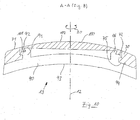
Am gelenkseitigen Ende 16 des ersten Gelenkschienenschenkels 10 weist dieser einen Gelenkring 70 auf, dessen Mittelachse die Schwenkachse 12 ist. Der Gelenkring 70 ist bevorzugt einstückig mit dem ersten Gelenkschienenschenkel 10 verbunden. Der Gelenkring 70 besitzt eine Außenseite 71, eine Innenseite 72 sowie eine sich von der Innenseite 72 ein Stück in Richtung zur Schwenkachse 9 erstreckende Ringstufe 73 auf.At the joint-
Der zweite Gelenkschienenschenkel 11 besitzt eine Außenseite 80 und einen Innenseite 81 sowie eine erste Längsbegrenzungskante 82 und eine zweite Längsbegrenzungskante 83 sowie eine Schmalseitenbegrenzungskante 84. Der zweite Gelenkschienenschenkel 11 ist hinsichtlich seiner Raumform im Wesentlichen als ein in Längsrichtung und Querrichtung gewölbter plattenförmiger Körper aufgebaut, wobei die Wölbungen in Längs- und Querrichtung an die anatomischen Gegebenheiten im Bereich des Mittelfußes an einer Fußinnenseite angepasst sind. Zum freien Ende 15 hin sowie zu den Längsbegrenzungskanten 82, 83 hin ist der zweite Gelenkschienenschenkel 11 wie auch der erste Gelenkschienenschenkel 10 sich jeweils in der Materialstärke verjüngend ausgebildet, sodass z. B. eine im Querschnitt in etwa linsenförmige Räumform ausgebildet ist. In etwa parallel zu den Längsbegrenzungskanten 82, 83 weist der zweite Gelenkschienenschenkel 11 schlitzförmige Öffnungen 85 auf, sodass ein Mittelsteg 86 sowie Randstege 87 und zwischen den Randstegen, 87 und dem Mittelsteg 86 angeordnete Zwischenstege 88 ausgebildet sind.The second
Das gelenkseitige Ende 16 des zweiten Gelenkschienenschenkels 11 ist bevorzugt mit dem Gelenkschienenschenkel 11 einstückig verbunden und ist als Gelenkteller 90 ausgebildet, welcher mit dem Gelenkring 70 des ersten Gelenkschienenschenkels 10 die Gelenkeinrichtung 13 bildet. Wenn die erfindungsgemäße Vorrichtung von einem Patienten getragen wird und an dessen Fuß befestigt ist, ist der Gelenkteller 90 der Fußhaut zugewandt und liegt auf dieser auf. Der Gelenkring 70 ist außenseitig gegen den Gelenkteller 90 gesetzt. Der Gelenkteller 90 weist konzentrisch zur Ringöffnung des Gelenkrings 7 einen Ringsteg 91 auf, welcher sich vom Gelenkteller 90 ein Stück in Richtung des Innenraums des Gelenkrings 70 erstreckt. Der Ringsteg 91 sitzt spielfrei oder nahezu spielfrei innerhalb der Ringstufe 73 des Gelenkrings 70, sodass eine radiale Führung des Gelenktellers 90 und des Gelenkrings 70 zueinander gewährleistet ist. Zur axialen Festlegung des Gelenkrings 70 bezüglich des Gelenktellers 90 sind an den Ringsteg 91 Rästnasensegmente 92 (Fig.9) angeformt, welche mit einer Oberseite der Ringstufe 73 zusammenwirken und somit eine axiale Festlegung der Gelenkschienenschenkel 10 und 11 zueinander gewährleisten. Die Anordnung der Rastnasensegmente 92 wird im Zusammenhang mit der Fig. 9 näher beschrieben werden. Um ein sicheres Fügen der Gelenkeinrichtung durch Aufstecken des Gelenkrings 70 auf den Gelenkteller 90 und Verrasten der Rastnasensegmente 92 mit der Ringstufe 73 zu gewährleisten, ist es zweckmäßig, die Rastnasensegmente 92 nicht vollumfänglich am Ringsteg 91 anzuordnen, damit durch die Materialelastizität der Gelenkring 70 beim Fügen auffedern kann.The joint-
Gemäß einer besonders bevorzugten Ausführungsform (Fig. 9) weist der Gelenkteller 90 eine im Querschnitt Kalottenförmige, insbesondere Kugelkalotten-förmige Raumform auf und besitzt eine zum Fuß hingewandte Seite 93 und eine zum Gelenkring 70 hingewandte Außenseite 94, welche korrespondierend zur Innenseite 93 ebenfalls, insbesondere im Bereich außerhalb des Ringstegs 91, Kalotten-förmig oder teilbereichsweise Kalotten-förmig ausgebildet ist. Korrespondierend hierzu weist der Gelenkring 70 einer der Außenseite 71 gegenüberliegende Innenseite 75 auf, welche in ihrer Raumform derart ausgebildet ist, dass sie flächig auf der korrespondierenden Innenseite 93 des Gelenktellers 90 im Bereich außerhalb des Ringstegs 91 aufliegt.According to a particularly preferred embodiment (FIG. 9), the
Zusätzlich zu den Rastnasensegmenten 92 weist der Ringsteg 91 an seinem freien Ende einen weiteren Rastring 96 oder Rastringsegmente auf, welche zur Befestigung einer deckelartigen Verschlusseinrichtung 100 (vergleiche Fig. 8, 10) dienen.In addition to the latching
Die deckelartige Verschlusseinrichtung 100 weist zum Rastringsteg 96 korrespondierende Gegenrastmittel 101 auf, sodass die Verschlusseinrichtung formschlüssig mit dem Gelenkteller 90 bzw. dessen Ringsteg 91 verbindbar ist. Die Verschlusseinrichtung 100 weist eine Außenseite 102 auf, die in ihrer Raumform derart ausgebildet ist, dass ein harmonischer Übergang von der Oberseite 73 des Gelenkrings 70 gewährleistet ist. Die Verschlusseinrichtung 100 dient dazu, die offene Gelenkeinrichtung zu verschließen und somit vor Verschmutzung und/oder Beschädigung zu schützen. Bevorzugt ist die Verschlusseinrichtung 100 mit Spiel zur Innenseite 72 des Gelenkrings eingesetzt, um unerwünschte Geräusche und/oder überhöhte Reibung zu vermeiden.The cover-
Somit ist in einfacher Art und Weise eine leicht zu montierende Gelenkeinrichtung 13 geschaffen, welche eine außerordentlich hohe Biege-Belastbarkeit bei gleichzeitig geringer Materialdicke aufweist und zudem mit nur wenigen Bauteilen auskommt. Außerdem bewirkt die Ausbildung der Gelenkeinrichtung 13 nach Art eines Ringgelenks, dass in die Gelenkeinrichtung 13 hohe Biegekräfte und Biegemomente einleitbar sind, ohne deren Leichtgängigkeit zu beeinträchtigen oder derer Verschleiß übermäßig zu fördern. Dies ist vor allem auf die große Stützweite, welche durch ein außenseitiges Eingreifen der Rastnasensegmente 92 in eine innenseitige Ringstufe 72 des Gelenkrings 70 ermöglicht wird, zurückzuführen.Thus, in a simple manner, an easy-to-install
Somit ist die Gelenkschiene 9 im Wesentlichen aus lediglich zwei Einzelteilen gebildet, welche die Funktion der Schiene 9 sicherstellen. Die Verschlusseinrichtung 100 besitzt lediglich eine Verschlussfunktion und ist zur Ausbildung des Gelenks nicht notwendig. Besonders vorteilhaft bei einer solchen Ausgestaltung der Gelenkeinrichtung 13 ist, dass die im Bereich des Großzehengrundgelenks an einer eventuell vorhandenen Pseudoexostose des Patientenfußes anliegende Innenseite 93 des Gelenktellers 90 eine glatte Oberfläche aufweist, d.h. keine überstehende oder vorstehende Teilbereiche oder Kanten aufweist, was den Tragekomfort erheblich erhöht. Durch die Kalotten-förmige Ausgestaltung ist die größtmögliche Druckentlastung empfindlicher Bereiche des Fußes (Pseudoexostose) und somit eine Schmerzentlastung des Patienten sichergestellt, da die eingeleitete Druckkraft F2 auf eine große Fläche verteilt wird. Entlang des Längsverlaufes (Fig. 11) der Gelenkschiene 9 ist dafür gesorgt, dass die Innenseite 51, die Innenseite 93 und die Innenseite 81 der Gelenkschienenbauteile 10, 11 einen stetigen, stufenfreien und geschmeidigen Verlauf aufweisen, sodass der Tragekomfort am Fuß weiter verbessert ist. Die schlitzförmigen Öffnungen 55 bzw. 85 weisen ggf. an deren Flankenflächen Verzahnungen 55a auf, welche eine Rutschsicherung für die durchzufädelnden Ringbandagen 6 darstellen.Thus, the
Die Gelenkschienenschenkel 10 und 11 schließen in ihrer Längserstreckung mit der Schwenkachse 12 einen Winkel α bzw. β ein (vergleiche Fig. 11). Die Winkel α und β sind derart gewählt, dass die Gelenkschiene 9 derart an einen Patientenfuß anlegbar ist, dass die Schwenkachse 12 in etwa mit der anatomischen Gelenkachse des Großzehengrundgelenks fluchtet, sodass bei einer Schwenkbewegung des Gelenkes mit am Fuß befestigten, Gelenkschienenschenkeln 10 und 11 eine kinematisch weitgehend an die anatomischen Bedingungen des Großzehengrundgelenks angepasste Schwenkbewegung der Gelenkschiene 9 ermöglicht wird. Weiterhin sind die Winkel α und β derart gewählt, dass für eine zur Fußaußenseite hin schief gestellte Großzehe (Hallux-valgus-Stellung) eine Korrektur in Richtung hin zu einer orthopädischen Normalstellung erreichbar ist. Selbstverständlich liegt es auch im Bereich der Erfindung, die Winkel α und β derart zu wählen, dass eine seltener auftretende so genannte Hallux-varus-Stellung, d. h. eine Zehenschiefstellung, die ausgehend von der Normalstellung hin zur Fußinnenseite verschoben ist, korrigiert werden kann. Die Auswahl der Winkel α und β nach den oben genannten Kriterien ist selbstverständlich für alle in dieser Anmeldung skizzierten Ausführungsformen möglich und nicht auf die Ausführungsform gemäß den Fig. 7 bis 11 beschränkt. Je nach Grad der auftretenden Zehenschiefstellung und der erwünschten Korrekturkraft hat sich für den Winkel α ein Bereich zwischen 75° und 115° bewährt. Innerhalb dieses Bereichs ist ein Großteil der auftretenden Hallux-valgus- und Hallux-varus-Schiefstellungen korrigierbar. Selbstverständlich kann in extremen Einzelfällen auch ein Winkel α außerhalb dieses Bereichs notwendig werden. Für den Winkel β hat sich ein Winkel von etwa 70° bis 110° bewährt, um einen Großteil der üblicherweise auftretenden Hallux-valgus- und/oder Hallux-varus-Stellungen zu korrigieren. Selbstverständlich gilt auch für den Winkel β, dass er in Einzelfällen größer oder kleiner zu wählen ist.The
Eine weitere Ausführungsform der Gelenkschiene 9 der erfindungsgemäßen Vorrichtung 1 (Fig. 12) ist im Wesentlichen identisch aufgebaut wie die Ausführungsform gemäß den Fig. 7 und beruht hinsichtlich der Korrektur der Zehenfehlstellungen auf dem gleichen Wirkprinzip. Im Unterschied zur Ausführungsform gemäß den Fig. 7 bis 11 ist bei der Ausführungsform gemäß den Fig. 12 bis 17 lediglich die Gelenkeinrichtung 13 etwas anders gestaltet. Die Innenseite 72 des Gelenkrings 70 ist in ihrer axialen Längserstreckung etwas größer ausgebildet. Zudem verfügt der Ringsteg 91 des Gelenktellers 90 lediglich über die Rastnasensegmente 92, nicht jedoch über die aufgesetzten Rastnasensegmente 96 zur Halterung der Verschlusseinrichtung 100.A further embodiment of the
Die Verschlusseinrichtung 100 (vergleiche Fig. 13) ist derart in den Gelenkring 70 eingesetzt, dass eine Ringaußenwandung 105 der Verschlussvorrichtung 100 mit der Innenseite 72 des Gelenkrings 70 derart zusammenwirkt, dass die Verschlussvorrichtung 100 mittels eines Klemmsitzes, ggf. auch mittels eines Klebsitzes bezüglich des Gelenkrings 70 befestigt ist. Bei dieser Konstruktion ist von Vorteil, dass die Verschlusseinrichtung 100 nicht relativ zum Gelenkring 70 bewegt wird, sodass eine Scheuerwirkung auf einen ggf. die Gelenkschiene mitsamt der Gelenkeinrichtung 16 umgebenden Strumpf oder eine Innenseite des Schuhs minimiert ist. Somit ist sichergestellt, dass zwischen den Teilbereichen 50, 102, 80 der Außenseite der Gelenkschiene 9 bei Betätigung der Gelenkschiene keine Relativbewegung der Flächenabschnitte 80, 100, 70 zueinander im Bereich der Gelenkeinrichtung 13 stattfindet. Ein weiterer Unterschied ist, dass die Gelenkgleitflächen 94 des Gelenktellers 90 und die korrespondierende Fläche 75 des Gelenkrings 70 als planare Ringflächen ausgebildet sind, was eine Konstruktionsvereinfachung dahingehend darstellt, dass die radiale Führung des Gelenkrings 70 bezüglich des Gelenktellers 90 ausschließlich über eine Außenseite 91a des Ringstegs 91 und über eine Innenseite 73a der Ringstufe 73 erfolgt.The closure device 100 (cf. FIG. 13) is inserted into the
Selbstverständlich liegt es auch im Bereich der Erfindung, die Verschlusseinrichtung 100 nach Art der Ausführungsform gemäß den Fig. 12 bis 17 auf eine Ausführungsform der Gelenkeinrichtung 13 gemäß den Fig. 7 bis 12 zu übertragen. Gleiches gilt für die Ausbildung der Gleitflächen 75, 94 hinsichtlich der Übertragung des Prinzips gemäß den Fig. 7 bis 12 auf eine Gelenkeinrichtung 13 gemäß den Fig. 13 bis 17.Of course, it is also within the scope of the invention to transfer the
Aus einem Längsschnitt der Ausführungsform gemäß den Fig. 12 und 13. (Fig. 16) geht hervor, dass der wirksame Korrekturwinkel β zwischen der Schwenkachse 12 und den am Fuß anliegenden wirksamen Bereichen der Gelenkschiene 9 jeweils 90° ist. Weiterhin weisen die Gelenkschienenschenkel 10 und 11 in ihrem wirksamen Längsverlauf entlang ihrer Seiten 51 und 81 eine gerade Raumform auf, welche nicht in besonderem Maße an den anatomischen Verlauf eines Fußes bzw. einer Großzehe angepasst ist. Somit stellt eine derartige Ausführungsform der Gelenkschiene eine vereinfachte, aber für eine Großzahl der zu behandelnden Fälle wirkungsvolle Ausgestaltung der Gelenkschiene 9 dar. Der korrespondierende Winkel α und β in Fig. 11 wurde der Einfachheit halber zwischen der Schwenkachse 12 und der Äußenlinie eingezeichnet, was jedoch keinen wesentlichen Unterschied macht. Gemeint ist in jedem Fall der wirksame Winkel einer gedachten Gelenkschienenschenkel-Wirkachse zur Schwenkachse 12, wobei im Falle einer vollständig frei geformten, an die anatomischen Gegebenheiten des menschlichen Fußes angepassten Gelenkschiene gemäß Fig. 11 die zeichnerische Festlegung einer solchen Wirksachse nur eine grobe Schätzung sein kann. Somit wird festgestellt, dass die Winkel α und β gemäß Fig. 16 und die Winkel α und β gemäß Fig. 11 im Prinzip die gleichen Wirkwinkel darstellen sollen.From a longitudinal section of the embodiment according to FIGS. 12 and 13 (FIG. 16), it can be seen that the effective correction angle β between the
In der Längsschnittdarstellung gemäß Fig. 17 ist die Ausführungsform der Gelenkschiene 9 gemäß den Fig. 12 und 13 mit einer eingesetzten Verschlusseinrichtung 100 gezeigt.The embodiment of the
Eine weitere Ausführungsform der Gelenkeinrichtung 13 (Fig. 18) der Gelenkschiene 9 der erfindungsgemäßen Vorrichtung 1 ist ebenfalls als so genanntes Ringscheibengelenk mit einem Gelenkteller 90 und einem Gelenkring 70 aufgebaut. Der Gelenkteller 90 weist eine zur Fußhaut weisende Innenseite 93 und eine gegenüberliegende Außenseite 94 auf. Von der Außenseite 94 erstreckt sich ein Stück in Richtung weg vom Fuß des Patienten ein Ringsteg 91, welcher eine Ringstegaußenfläche 91a besitzt. Die Ringstegaußenfläche 91a dient zur radialen Führung des Gelenkrings 70 und wirkt spielfrei oder mit geringem Spiel mit einer Gelenkringinnenseite 73a zusammen.A further embodiment of the hinge device 13 (FIG. 18) of the
Der Gelenkteller 90 ist wie in den vorangegangenen Ausführungsformen bevorzugt Kalotten-förmig, insbesondere Kugelkalotten-förmig ausgebildet und weist außerhalb des Ringstegs 91 einen Teilbereich der Außenseite 94 auf, welcher als Gelenkgleitfläche dient und mit einer korrespondierenden Gelenkgleitfläche 78 des Gelenkrings 70 zusammenwirkt. Die Gelenkgleitflächen haben eine Kalottenabschnitts-förmige Raumform. Bei der Ausführungsform gemäß der Fig. 18 ist die Höhe der Ringstufe 73 des Gelenkrings 70 derart gewählt, dass eine Oberseite 73b der Ringstufe mit einer Oberseite 91b des Ringstegs 91 bündig abschließt oder etwas übersteht. Somit ist durch das Zusammenwirken der Ringstege 91 und des Gelenkrings 70 mit deren Flächen 91a und 73a eine radiale Führung der Gelenkschienenschenkel 10, 11 gewährleistet. Die axiale Führung der Gelenkschienenschenkel 10, 11 zueinander wird über die Gleitfläche 78 und deren korrespondierenden Gleitflächenabschnitt der Außenseite 94 des Gelenktellers 90 in einer Richtung sichergestellt. In der zu dieser Richtung entgegengesetzten Richtung ist die axiale Festlegung der Gelenkschienenschenkel 10, 11 bzw. des Gelenkrings relativ zum Gelenkteller 90 wie folgt sichergestellt.As in the previous embodiments, the
Die Verschlusseinrichtung 100 ist zusätzlich zu ihrer Verschlussfunktion der Gelenkeinrichtung 13 als Axiallager weitergebildet. Die Verschlusseinrichtung 100 weist einen Verschlusseinrichtungskörper 103 auf, welcher wie in den vorbeschriebenen Ausführungsformen im Wesentlichen die Gelenkeinrichtung 13 bedeckt und somit vor Verschmutzungen schützt. Vom Verschlusseinrichtungskörper 103 erstreckt sich gegenüberliegend von der Oberseite 102 ein Ringsteg 105, welcher im Durchmesser derart bemessen ist, dass er innerhalb des Ringstegs 91 des Gelenktellers 90 in den vom Ringsteg 91 umgrenzten Raum einsteckbar ist. Außerhalb des Ringstegs 105 weist die Verschlusseinrichtung 100 einen umlaufenden Vorsprung 106 auf, welcher in radialer Richtung derart bemessen ist, dass er den Ringsteg 91 radial ein Stück überragt und auf der Ringstufenoberseite 73b der Ringstufe spielfrei oder mit geringem axialen Spiel aufliegt. Somit dient eine Unterseite 107 des Ringvorsprungs 106, welche mit der Oberseite 73b der Ringstufe 73 zusammenwirkt, als axiales Widerlager. Damit durch eine solche Gelenkkonstruktion hohe Biegekräfte, welche die Gelenkschiene 9 ausüben muss, beschädigungsfrei und dauerhaft übertragen werden können, ist die Verschlussvorrichtung 100 zweckmäßigerweise mit dem Gelenkteller bzw. dessen Ringsteg 91 an einer oder mehreren deren Berührungsflächen verklebt oder anderweitig sicher befestigt.The
Auch diese Gelenkeinrichtung 9 hat den besonderen Vorteil, dass die an den besonders empfindlichen Bereichen des Fußes anliegenden Flächen 93, z. B. im Bereich einer Pseudoexostose, glatt ausgebildet sind, d. h. dass keine Überstände oder Vertiefungen die dortigen Hautbereiche reizen. Zudem weist die Gelenkausführung gemäß Fig. 18 eine besonders hohe Biegesteifigkeit auf und ist auch durch missbräuchliches Überbiegen der Schiene nicht ohne weiteres zerlegbar, d. h. dass durch unsachgemäße Behandlung durch den Patienten, z. B. durch Tordieren, Überbiegen oder dergleichen es ausgeschlossen ist, dass die beiden Gelenkschienenschenkel 10, 11 voneinander trennbar sind.Also, this
Als bevorzugter Werkstoff für die Gelenkschienen hat sich neben Kunststoff, insbesondere ein schlagzäher und hautverträglicher Kunststoff, z. B. aus der Gruppe der Polykarbonate, bewährt.As a preferred material for the joint rails in addition to plastic, in particular an impact-resistant and skin-friendly plastic, z. B. from the group of polycarbonates, proven.
Im Folgenden wird anhand der Fig. 19 bis 21 die Befestigung der Gelenkschiene 9 an dem Patientenfuß und die Führung bzw. Fädelung der Ringbandagen 5, 6 durch die Schlitzöffnungen 55, 85 der Gelenkschienen 9 näher beschrieben.The fastening of the
Die Ringbandage 6 im Bereich des Großzehs (Fig. 19)dient als Befestigungseinrichtung und weist den Schlaufenkörper 60 sowie freie Enden 61 auf. Der Schlaufenkörper 60 umgrenzt zusammen mit dem ersten Gelenkschienenschenkel 10 einen Innenraum 62, in dem die Zehe des Patienten angeordnet ist. Die freien Enden 61 sind von der Innenseite 51 her durch die schlitzförmigen Öffnungen 55 geführt und um den Randsteg 57, diesen umschließend, herumgeschlagen. Somit kommt das freie Ende 61 der Ringbandage 6 benachbart zum Gelenkschienenschenkel 10 außenseitig mit dem Schlaufenkörper 60 zur Anlage. Das freie Ende 61 ist zweckmäßigerweise mittels eines Klettverschlusses 63 an der Außenseite des Schlaufenkörpers lösbar befestigt. Diese Art der Befestigung des freien Endes 61 kann auf beide freien Enden 61 der Ringbandage 6 angewendet werden. Es ist jedoch ggf. auch zweckmäßig, ein freies Ende 61 um einen Randsteg 57 herumzuschlagen und ggf. mit dem Schlaufenkörper 60 fest zu vernähen und nur ein weiteres freies Ende 61 mittels einer Klettverbindung oder dergleichen vergleichbare lösbare Flächenverbindung mit dem Schlaufenkörper 60 zu verbinden.The
Die Ringbandage 5 dient als Befestigungseinrichtung und als Bandage zur Stützung und Wiederaufrichtung des Quergewölbes des Fußes und ist ebenfalls einen Schlaufenkörper 50 bildend mit dem zweiten Gelenkschienenschenkel 11 verbunden. Die Ringbandage 5 weist ebenfalls freie Enden 51 auf. Ein freies Ende 51 ist von der Innenseite 81 her durch die erste schlitzförmige Öffnung 85 nahe der Fußunterseite geführt und durchdringt diese, liegt außenseitig auf dem ersten Zwischensteg 88 auf und durchdringt die zweite Schlitzöffnung 85 von der Außenseite 80 her, liegt im Bereich des Mittelsteges 86 auf der Innenseite 81 auf und durchdringt die nächste schlitzförmige Öffnung 85 von der Innenseite 81 her hin zur Außenseite, liegt auf dem zweiten Zwischensteg 88 außenseitig an und durchdringt die letzte Schlitzöffnung 85 von der Außenseite 80 her nach innen. Das überstehende freie Ende 51 ist z.B. im Bereich des Ristes des Fußes anliegend angeordnet. Der restliche Bereich der Ringbandage 5, welcher nicht an der Fädelung durch den zweiten Gelenkschienenschenkel 11 beteiligt ist, ist den Fuß den Patienten umgebend um die Fußunterseite und die Fußoberseite geführt, überlappt den zweiten Gelenkschienenschenkel 11 im Bereich der Schlitzöffnungen 85 und ist im dem zweiten freien Ende 51 außenseitig am Schlaufenkörper 50 befestigt. Als Befestigungsmittel haben sich Klettverschlüsse, insbesondere Hakenklettverschlüsse oder Pilzklettverschlüsse 53 bewährt. Bei dieser Art der Fädelung der Ringbandage 5 durch den zweiten Gelenkschienenschenkel 11 und das anschließende Umgeben des gesamten Mittelfußes ist von besonderem Vorteil, dass die Randbegrenzungskanten 83 des Gelenkschienenschenkels 11 nicht direkt auf der Fußhaut aufliegen und somit eine Druckstellenbildung verhindert ist.The
Gegebenenfalls kann es auch zweckmäßig sein, die zwei zentraler angeordneten Schlitzöffnungen 85 entfallen zu lassen und die Ringbandage 5 lediglich durch die äußersten Schlitzöffnungen 85 ohne den Umweg um den Mittelsteg 86 zu führen. Diese Ausführungsform hat den Vorteil, dass im Bereich des Gelenkschienenschenkels 11, in dem dieser am Fuß anliegt, weniger Unebenheiten und somit weniger Druckstellen am Fuß auftreten. Im Bereich des von Schlaufenkörper 50 umgebenen Innenraums 52, in dem der Mittelfußbereich des Patienten angeordnet ist, ist zweckmäßigerweise im Bereich der Fußunterseite des Patienten die Pelotte 14 mit der Ringbandage 5 ebenfalls über Klettverbindungselemente 53 verbunden.Optionally, it may also be expedient to omit the two centrally arranged
Ein weiterer Vorteil dieser Art der Fädelung der Ringbandage 5. ist, dass zum Anlegen der Schiene 9 keine Fädelung durch die Öffnungen 85 des Gelenkschienenschenkels 11 notwendig ist, sondern lediglich die fertig gefädelte Ringbandage um den Fuß geschlagen werden muss und an dessen Unterseite festgezurrt und dort befestigt werden muss. Somit ist ein leichtes Einstellen oder Nachstellen der Spannung der Ringbandage 5 und somit deren Korrekturwirkung auf das Quergewölbe des Patientenfußes im Bereich des Mittelfußes ermöglicht.Another advantage of this type of threading the
Eine weitere Ausführungsform der Fädelung der Ringbandage 5 durch den zweiten Gelenkschienenschenkel 11 (gemäß Fig. 5) erfolgt derart, dass ein erstes freies Ende eine Schlitzöffnung 85 von der Innenseite 81 her durchgreifend, den Randsteg 87 im Bereich der Fußunterseite umgreifend geführt ist und außenseitig am Schlaufenkörper im Bereich der Fußunterseite mit diesem mittels Verbindungselementen 53 verbunden ist. Das andere freie Ende 51 ist im Bereich der Fußoberseite von der Innenseite 81 her durch eine randliche Schlitzöffnung 85 nach außen geführt, liegt außenseitig am ersten Zwischensteg 88 an und durchdringt eine weitere schlitzförmige Öffnung 85 in Richtung zur Innenseite 81 hin, liegt innenseitig am Mittelsteg 86 an, umschlingt diesen durch eine weitere Öffnung 85 und ist außenseitig in Richtung zur Fußoberseite hin, den Gelenkschienenschenkel 11 teilweise überlappend, geführt. Das freie Ende 51 kann somit mittels Verschlusselementen 53 außenseitig am Schlaufenkörper 50 befestigt werden.A further embodiment of the threading of the
Die Ringbandagenführung gemäß Fig. 21 hat den Vorteil, dass die freien Enden in jedem Fall außenseitig am Schlaufenkörper 50 angeordnet sind, sodass zum Fuß hin keine Stufe in Höhe der Materialstärke zuzüglich der Verbindungselemente 51 entsteht und somit Druckstellen am Fuß vermieden werden. Auch bei dieser Ausführungsform ist es selbstverständlich möglich, das fußoberseitige freie Ende lediglich durch eine randliche Schlitzöffnung 85 zu führen, sodass dieses den Randsteg 87 umgreift und außenseitig auf dem Schlaufenkörper 50 befestigt werden kann. In diesem Fall entspricht die Fädelung bzw. Umschlingung der Ringbandage 5 der der Ringbandage 6 im Bereich des Großzehs. Auch kann bei dieser Ausführungsform im Bereich der Fußunterseite die Pelotte 14 mittels Klettelementen 53 an einer Innenseite des Schlaufenkörpers 50, insbesondere lösbar, befestigt werden.The annular bandage guide according to FIG. 21 has the advantage that the free ends are in each case arranged on the outside of the
Die nicht starre, in Grenzen schwimmende Anbindung der Vorrichtung 1 an die Innenseite des Fußes hat den Vorteil, dass sich die Vorrichtung 1 individuell an die anatomischen Randbedingungen anpassen kann, d.h. z.B. dass sich die Schwenkachse 12 der Gelenkschiene 9 nach dem Anlegen der Vorrichtung 1 selbsttätig fluchtend mit der anatomischen Gelenkachse des Großzehengrundgelenkes ausrichtet.The non-rigid, floating within the
Claims (37)
dadurch gekennzeichnet, dass die Biegeschiene (9) als Gelenkbiegeschiene ausgebildet ist, welche in der Flexion-Extensionsrichtung (20) des oder der zu korrigierenden Zehen gelenkig ausgebildet ist.An orthopedic device for correcting toe deformities, comprising a first fastening device (8a, 6) in the area of the big toe, a second fastening device (8b, 5) in the region of the metatarsus and a bending rail (9) which is movable by the fastening devices (8a, 8b, 5 , 6) and the device extends along the inner side of the foot,
characterized in that the bending rail (9) is designed as a hinge bending rail, which is articulated in the flexion extension direction (20) of the one or more toes to be corrected.
dadurch gekennzeichnet, dass die Gelenkschienenschenkel (10, 11) im Querschnitt linsenförmig ausgebildet sind.Device according to one or more of the preceding claims,
characterized in that the hinge rail legs (10, 11) are formed lenticular in cross section.
dadurch gekennzeichnet, dass die Biegeschiene (9) eine Gelenkeinrichtung (13) aufweist, welche eine Schwenkachse (12) aufweist, die in etwa der Gelenkachse des Großzehengrundgelenks in der Flexion-Extensionsrichtung entspricht.Device according to one or more of the preceding claims,
characterized in that the bending rail (9) has a hinge device (13) which has a pivot axis (12) which corresponds approximately to the joint axis of the big toe joint in the flexion extension direction.
dadurch gekennzeichnet, dass die Vorrichtung (1) im Bereich des Mittelfußes eine erste Ringbandage (5) aufweist, welche den Mittelfuß vorzugsweise vollständig umgibt und mit dem Strumpf (2) in Verbindung steht.Device according to one or more of the preceding claims,
characterized in that the device (1) in the region of the metatarsus has a first annular bandage (5), which preferably completely surrounds the metatarsus and is in communication with the stocking (2).
dadurch gekennzeichnet, dass die Ringbandagen (5, 6) aus einem biegsamen, schmiegsamen, zirkulär zugstarren Material ausgebildet sind.Device according to one or more of the preceding claims,
characterized in that the annular bandages (5, 6) are formed from a flexible, pliable, circular tensile material.
dadurch gekennzeichnet, dass die Biegeschiene (9) einen ersten Gelenkschienenschenkel (10) und einen zweiten Gelenkschienenschenkel (11) aufweist, welche um eine Schwenkachse (12) schwenkbar mittels einer Gelenkeinrichtung (13) gelenkig verbunden sind.Device according to one or more of the preceding claims,
characterized in that the bending rail (9) has a first hinge rail leg (10) and a second hinge rail leg (11), which are pivotally connected about a pivot axis (12) by means of a hinge device (13).
dadurch gekennzeichnet, dass im Bereich der Fußsohle hinter den Grundgelenken der Zehen zur retrokapitalen Abstützung des Mittelfußes eine Spreizfußpelotte (14) eingesetzt ist.Device according to one or more of the preceding claims,
characterized in that a Spreizfußpelotte (14) is used in the region of the sole of the foot behind the base joints of the toes for retrokapitalen support of the metatarsus.
dadurch gekennzeichnet, dass die Gelenkeinrichtung (13) aus dem ersten Gelenkschienenschenkel (10), dem zweiten Gelenkschienenschenkel (11) und einer Gelenkschienenschenkel-Verbindungseinrichtung (14a), insbesondere einer Hohlniet, aufgebaut ist.Device according to one or more of the preceding claims,
characterized in that the hinge device (13) of the first joint rail leg (10), the second joint rail leg (11) and a joint rail leg connection means (14a), in particular a tubular rivet, is constructed.
dadurch gekennzeichnet, dass die Gelenkschienenschenkel (10, 11) jeweils ein freies Ende (15) und ein gelenkseitiges Ende (16) aufweisen.Device according to one or more of the preceding claims,
characterized in that the hinge rail legs (10, 11) each have a free end (15) and a hinge-side end (16).
dadurch gekennzeichnet, dass die gelenkseitigen Enden (16) in etwa eine Kugelkalottenraumform aufweisen und zueinander derart korrespondierend ausgebildet sind, dass die jeweils gelenkseitigen Enden (16) der Gelenkschienenschenkel (10, 11) formschlüssig passend ineinander legbar sind.Device according to one or more of the preceding claims,
characterized in that the hinge-side ends (16) have approximately a Kugelkalottenraumform and are formed corresponding to each other such that the respective joint-side Ends (16) of the joint rail legs (10, 11) are positively fitting into one another.
dadurch gekennzeichnet, dass die Gelenkschienenschenkel (10, 11) und die Gelenkeinrichtung (13) in ihrer Raumform an die Fußkontur des Patienten angepasst sind.Device according to one or more of the preceding claims,
characterized in that the joint rail legs (10, 11) and the hinge device (13) are adapted in their spatial form to the foot contour of the patient.
dadurch gekennzeichnet, dass die gelenkseitigen Enden (16) der Gelenkschienenschenkel (10, 11) eine um die Achse (12) rotationssymmetrische, zueinander korrespondierende Raumform aufweisen.Device according to one or more of the preceding claims,
characterized in that the hinge-side ends (16) of the hinge rail legs (10, 11) have a about the axis (12) rotationally symmetrical, mutually corresponding spatial shape.
dadurch gekennzeichnet, dass die Gelenkschienenschenkel (10, 11) aus Metall oder Kunststoff, insbesondere aus einer Kohlefaser-verstärkten dünnen Platte ausgebildet sind.Device according to one or more of the preceding claims,
characterized in that the hinge rail legs (10, 11) made of metal or plastic, in particular of a carbon fiber-reinforced thin plate are formed.
dadurch gekennzeichnet, dass durch die Biegeschiene (9) zur Lateralisierung des Großzehs eine Kraft F1 in Richtung zur Fußinnenseite hin auf den Großzeh ausübbar ist.Device according to one or more of the preceding claims,
characterized in that by the bending rail (9) for lateralization of the big toe a force F1 in the direction of the foot inside towards the big toe is exercisable.
Applications Claiming Priority (2)
| Application Number | Priority Date | Filing Date | Title |
|---|---|---|---|
| DE10240121A DE10240121B4 (en) | 2002-08-30 | 2002-08-30 | Orthopedic device for correcting toe deformities |
| EP03790816A EP1531768B1 (en) | 2002-08-30 | 2003-07-25 | Orthopaedic device for correcting abnormal positions of the toes |
Related Parent Applications (2)
| Application Number | Title | Priority Date | Filing Date |
|---|---|---|---|
| EP03790816.7 Division | 2003-07-25 | ||
| EP03790816A Division EP1531768B1 (en) | 2002-08-30 | 2003-07-25 | Orthopaedic device for correcting abnormal positions of the toes |
Publications (3)
| Publication Number | Publication Date |
|---|---|
| EP1688106A2 true EP1688106A2 (en) | 2006-08-09 |
| EP1688106A3 EP1688106A3 (en) | 2010-10-20 |
| EP1688106B1 EP1688106B1 (en) | 2014-05-14 |
Family
ID=29225198
Family Applications (2)
| Application Number | Title | Priority Date | Filing Date |
|---|---|---|---|
| EP03790816A Revoked EP1531768B1 (en) | 2002-08-30 | 2003-07-25 | Orthopaedic device for correcting abnormal positions of the toes |
| EP06008529.7A Expired - Lifetime EP1688106B1 (en) | 2002-08-30 | 2003-07-25 | Orthopedic device for correcting abnormal positions of toes |
Family Applications Before (1)
| Application Number | Title | Priority Date | Filing Date |
|---|---|---|---|
| EP03790816A Revoked EP1531768B1 (en) | 2002-08-30 | 2003-07-25 | Orthopaedic device for correcting abnormal positions of the toes |
Country Status (10)
| Country | Link |
|---|---|
| US (1) | US7396338B2 (en) |
| EP (2) | EP1531768B1 (en) |
| JP (1) | JP4917752B2 (en) |
| CN (1) | CN100528108C (en) |
| AT (1) | ATE324090T1 (en) |
| AU (1) | AU2003251638A1 (en) |
| DE (3) | DE10240121B4 (en) |
| ES (2) | ES2486866T3 (en) |
| HK (1) | HK1080280A1 (en) |
| WO (1) | WO2004019835A2 (en) |
Cited By (1)
| Publication number | Priority date | Publication date | Assignee | Title |
|---|---|---|---|---|
| WO2016166614A1 (en) * | 2015-04-14 | 2016-10-20 | Eumedica Srl | Orthopaedic device for hallux valgus |
Families Citing this family (44)
| Publication number | Priority date | Publication date | Assignee | Title |
|---|---|---|---|---|
| DE102004008909A1 (en) | 2004-02-24 | 2005-09-08 | Bauerfeind Ag | Orthosis for correcting the position of a body joint |
| US11690746B2 (en) | 2004-04-02 | 2023-07-04 | Applied Biokinetics Llc | Pre-cut adhesive supports for anatomical support, pain reduction, or therapeutic treatment |
| US8356427B2 (en) * | 2006-09-25 | 2013-01-22 | Grd Biotech, Inc. | Foot support device and method |
| US7959588B1 (en) * | 2007-04-25 | 2011-06-14 | Mark Wolpa | Pressureable compression wrap |
| DE202008004213U1 (en) | 2008-03-27 | 2009-08-13 | Hallufix Ag | Orthopedic device for correcting toe deformities |
| DE202008004214U1 (en) | 2008-03-27 | 2009-08-13 | Hallufix Ag | Orthopedic device for correcting toe deformities |
| ES2440277T3 (en) * | 2008-05-06 | 2014-01-28 | J.W. Barry Bruckmann | Musculoskeletal mobilization structures |
| JP4355364B1 (en) * | 2008-05-26 | 2009-10-28 | 原田正則 | Supporter structure for preventing or treating diseases associated with foot deformation |
| US8870876B2 (en) | 2009-02-13 | 2014-10-28 | Tarsus Medical Inc. | Methods and devices for treating hallux valgus |
| JP5302111B2 (en) * | 2009-06-09 | 2013-10-02 | 悦蔵 福田 | Hallux valgus correction tool |
| GB0911953D0 (en) * | 2009-07-09 | 2009-08-19 | Materialise Nv | An artificial exoskeleton device, an orthotic or a prosthetic device comprising an integrated hinge structure |
| US8277459B2 (en) | 2009-09-25 | 2012-10-02 | Tarsus Medical Inc. | Methods and devices for treating a structural bone and joint deformity |
| US9675491B1 (en) * | 2009-12-10 | 2017-06-13 | Anthony E Seaman | Hallux valgus brace |
| WO2011086716A1 (en) * | 2010-01-15 | 2011-07-21 | 独立行政法人科学技術振興機構 | Device for correcting hallux valgus and method for producing device for correcting hallux valgus |
| US8652141B2 (en) | 2010-01-21 | 2014-02-18 | Tarsus Medical Inc. | Methods and devices for treating hallux valgus |
| US7988602B1 (en) * | 2010-01-27 | 2011-08-02 | Janzen Michael L | Method and apparatus for treating plantar fasciitis |
| GB2477281B (en) * | 2010-01-27 | 2012-04-04 | Meditex Ltd | Podiatric device |
| FR2957246B1 (en) * | 2010-03-10 | 2013-02-08 | Sarl Pody Concept | ORTHOPEDIC DEVICE FOR THE TREATMENT OF HALLUX VALGUS BY REACTATION OF HALLUX VALGUS BY MECHANICAL EFFECT |
| US8696719B2 (en) | 2010-06-03 | 2014-04-15 | Tarsus Medical Inc. | Methods and devices for treating hallux valgus |
| DE102011051083A1 (en) | 2011-06-15 | 2012-12-20 | Vitus Maria Huber | Orthopedic device, in particular for correcting toe deformities |
| DE102011109431A1 (en) * | 2011-08-04 | 2013-02-07 | Bsn Medical Gmbh | Temporary rail |
| DE102012011467A1 (en) * | 2012-06-12 | 2013-12-12 | Otto Bock Healthcare Gmbh | orthosis |
| US9320637B2 (en) * | 2013-01-19 | 2016-04-26 | Derek Amanatullah | Dynamic hallux tension device for treatment of plantar faciitis |
| DE202013004834U1 (en) * | 2013-05-24 | 2013-06-10 | Hallufix Ag | Gel-side pad |
| US8782925B2 (en) | 2013-09-03 | 2014-07-22 | Jennus Athletics Company | Athletic shoe |
| CA2926018A1 (en) * | 2013-10-07 | 2015-04-16 | Albert CIESIELSKI | Orthopedic device for the correction of hallux valgus |
| US11278440B2 (en) | 2015-06-09 | 2022-03-22 | Christopher Richard Showalter | Orthopedic device providing metered toe traction with variable adduction, dorsiflexion and rotation angles, including lateral glide of the first metatarsal head |
| CN105326150B (en) * | 2015-11-23 | 2017-01-25 | 陕西科技大学 | Adjustable hallux valgus pain relieving bent last shoe for old people |
| USD808030S1 (en) * | 2016-03-01 | 2018-01-16 | Iwashouorimono Co., Ltd. | Pair of foot supporters |
| JP6746405B2 (en) * | 2016-07-01 | 2020-08-26 | 株式会社古河テクノマテリアル | Hallux valgus orthosis |
| US11285032B2 (en) * | 2017-03-22 | 2022-03-29 | Gryppers, Inc. | Grip enhancement and protection for the feet |
| US20190289956A1 (en) * | 2018-03-21 | 2019-09-26 | Jamelle Brian Eugene | Grip Enhancement and Protection for the Feet |
| CN106937899B (en) * | 2017-03-29 | 2020-07-28 | 延安大学附属医院 | External fixation brace for correcting varus and valgus deformity of knee joint |
| ES1200885Y (en) * | 2017-11-10 | 2018-02-28 | Picazo David Lucas | Device for the treatment of metatarsophalangeal predislocation syndrome |
| WO2019191248A1 (en) * | 2018-03-27 | 2019-10-03 | Norton Sean C | Splint device |
| JP6538925B2 (en) * | 2018-05-02 | 2019-07-03 | 有限会社サンパック | Affected part fixing tool |
| IT201800006628A1 (en) | 2018-06-25 | 2019-12-25 | POLYCENTRIC JOINT TENSIONER FOR ORTHOSIS OR ORTHOPEDIC SUPPORTS USED FOR REHABILITATION OF JOINTS | |
| TWI698218B (en) * | 2018-11-08 | 2020-07-11 | 施萬喜 | Correction device for joint deformation |
| USD931474S1 (en) * | 2019-04-04 | 2021-09-21 | Shenzhen Liangzilixing Industrial Co., Ltd. | Bunion corrector |
| CN111839855A (en) * | 2020-08-07 | 2020-10-30 | 广州泰柯碧缇科技有限公司 | Hallux valgus corrector |
| DE102021107084A1 (en) | 2021-03-22 | 2022-09-22 | Hallufix Ag | FOOT ORTHOSIS WITH SWIVEL JOINT FOR CORRECTING FOOT MALFUNCTIONS |
| DE102021107082A1 (en) | 2021-03-22 | 2022-09-22 | Elsa Vermögens- und Beteiligungs AG | FOOT ORTHOSIS WITH TOE SEGMENT IN THE FORM OF A STRAP FOR CORRECTING FOOT MALFUNCTIONS |
| US20240016644A1 (en) * | 2022-07-12 | 2024-01-18 | Scholl's Wellness Company Llc | Bunion splint assembly with adjustable support cushion |
| USD983979S1 (en) * | 2023-01-12 | 2023-04-18 | Keyun Cao | Toe splint |
Citations (8)
| Publication number | Priority date | Publication date | Assignee | Title |
|---|---|---|---|---|
| US892412A (en) | 1903-11-18 | 1908-07-07 | Achfeldt M | Foot appliance. |
| US933423A (en) | 1908-09-03 | 1909-09-07 | William H De Ford | Bunion-guard. |
| US1183062A (en) | 1915-09-27 | 1916-05-16 | William H De Ford | Bunion-guard. |
| US1213786A (en) | 1915-07-30 | 1917-01-23 | Scholl Mfg Company | Foot-treatment apparatus. |
| DE322651C (en) | 1920-07-05 | Karl Boesenberg Dr | Device to protect the ball of the foot and straighten the toes | |
| DE369381C (en) | 1921-07-29 | 1923-02-17 | Ludwig Rosenlehner | Device for aligning the big toe |
| DE1881215U (en) | 1962-05-31 | 1963-10-24 | William M Dr Scholl | FOOTBALL RAIL. |
| DE8902545U1 (en) | 1989-03-03 | 1989-05-03 | Heinrich Ad. Berkemann (Gmbh & Co), 2000 Hamburg, De |
Family Cites Families (25)
| Publication number | Priority date | Publication date | Assignee | Title |
|---|---|---|---|---|
| DE587233C (en) * | 1933-11-01 | Joseph Dickmann Dr | Bale protector | |
| DE316559C (en) * | ||||
| US1055810A (en) * | 1912-01-22 | 1913-03-11 | William M Scholl | Toe-straightening device. |
| US1746865A (en) * | 1925-12-18 | 1930-02-11 | Page Frederick George | Corrective appliance for feet |
| CH128592A (en) * | 1927-06-28 | 1928-11-01 | Frei & Kasser | Bandage for correcting the foot. |
| US2596038A (en) * | 1949-10-19 | 1952-05-06 | Margaret B Mayer | Bunion and foot corrective means |
| DE1285672B (en) * | 1963-11-25 | 1968-12-19 | Hilgers | Method for producing an elastic foot corset |
| JPS57188807U (en) * | 1981-05-24 | 1982-11-30 | ||
| JPH044738Y2 (en) * | 1988-10-08 | 1992-02-12 | ||
| US4962760A (en) * | 1989-05-01 | 1990-10-16 | Mesa, Inc. | Orthopedic restraint apparatus |
| DE4014728A1 (en) * | 1989-05-08 | 1990-11-15 | Franz Pistora | Bandage for reduction of outward turning of big toe - is held in place by tape which passes around heel |
| JP2913192B2 (en) * | 1989-12-18 | 1999-06-28 | 俊郎 中村 | Hallux valgus correction orthosis |
| JP2567424Y2 (en) * | 1991-12-06 | 1998-04-02 | アルケア株式会社 | Knee orthosis |
| US5542774A (en) * | 1994-12-08 | 1996-08-06 | Hoy; David J. | Orthotic joint |
| JPH09135855A (en) * | 1995-11-16 | 1997-05-27 | Nagasaki Kanae Gishi Seisakusho:Kk | Knee mounting tool |
| JPH1043224A (en) * | 1996-08-06 | 1998-02-17 | Nakamura Bureisu Kk | Appliance for hallux valgus |
| US5897515A (en) * | 1997-02-05 | 1999-04-27 | Light Weight Support Ab | Ankle-foot orthosis |
| US6001075A (en) * | 1997-12-12 | 1999-12-14 | Ex. P.H. | Dynamic splint |
| DE29824735U1 (en) * | 1998-03-02 | 2002-05-29 | Mayer Jana | Textile footwear |
| JP2964405B1 (en) * | 1998-10-12 | 1999-10-18 | 恵美子 村山 | Hallux valgus correction tool |
| DE19964578B4 (en) * | 1999-02-10 | 2008-11-13 | Gottinger Handelshaus GbR (vertretungsberechtigte Gesellschafter: Norbert G. Günther | orthosis |
| JP3765948B2 (en) * | 1999-07-16 | 2006-04-12 | 砂山靴下株式会社 | Foot supporter |
| US6254559B1 (en) * | 1999-08-30 | 2001-07-03 | Anthony C. Tyrrell | Adjustable hip joint assembly |
| US7200875B2 (en) * | 2001-11-06 | 2007-04-10 | John Dondero | Goggle for protecting eyes with movable lenses and methods for making and using the goggle |
| DE20205091U1 (en) * | 2002-04-02 | 2002-08-22 | Hauschild Christian | Device to relieve pain caused by a heel spur while walking and to support the foot muscles when running and jumping |
-
2002
- 2002-08-30 DE DE10240121A patent/DE10240121B4/en not_active Revoked
-
2003
- 2003-07-25 EP EP03790816A patent/EP1531768B1/en not_active Revoked
- 2003-07-25 JP JP2004531819A patent/JP4917752B2/en not_active Expired - Fee Related
- 2003-07-25 EP EP06008529.7A patent/EP1688106B1/en not_active Expired - Lifetime
- 2003-07-25 AU AU2003251638A patent/AU2003251638A1/en not_active Abandoned
- 2003-07-25 DE DE50303123T patent/DE50303123D1/en not_active Expired - Lifetime
- 2003-07-25 WO PCT/EP2003/008204 patent/WO2004019835A2/en active IP Right Grant
- 2003-07-25 AT AT03790816T patent/ATE324090T1/en active
- 2003-07-25 CN CNB03820343XA patent/CN100528108C/en not_active Expired - Fee Related
- 2003-07-25 ES ES06008529.7T patent/ES2486866T3/en not_active Expired - Lifetime
- 2003-07-25 DE DE20312159U patent/DE20312159U1/en not_active Expired - Lifetime
- 2003-07-25 US US10/525,852 patent/US7396338B2/en not_active Expired - Lifetime
- 2003-07-25 ES ES03790816T patent/ES2263055T3/en not_active Expired - Lifetime
-
2005
- 2005-11-25 HK HK05110737A patent/HK1080280A1/en not_active IP Right Cessation
Patent Citations (8)
| Publication number | Priority date | Publication date | Assignee | Title |
|---|---|---|---|---|
| DE322651C (en) | 1920-07-05 | Karl Boesenberg Dr | Device to protect the ball of the foot and straighten the toes | |
| US892412A (en) | 1903-11-18 | 1908-07-07 | Achfeldt M | Foot appliance. |
| US933423A (en) | 1908-09-03 | 1909-09-07 | William H De Ford | Bunion-guard. |
| US1213786A (en) | 1915-07-30 | 1917-01-23 | Scholl Mfg Company | Foot-treatment apparatus. |
| US1183062A (en) | 1915-09-27 | 1916-05-16 | William H De Ford | Bunion-guard. |
| DE369381C (en) | 1921-07-29 | 1923-02-17 | Ludwig Rosenlehner | Device for aligning the big toe |
| DE1881215U (en) | 1962-05-31 | 1963-10-24 | William M Dr Scholl | FOOTBALL RAIL. |
| DE8902545U1 (en) | 1989-03-03 | 1989-05-03 | Heinrich Ad. Berkemann (Gmbh & Co), 2000 Hamburg, De |
Cited By (1)
| Publication number | Priority date | Publication date | Assignee | Title |
|---|---|---|---|---|
| WO2016166614A1 (en) * | 2015-04-14 | 2016-10-20 | Eumedica Srl | Orthopaedic device for hallux valgus |
Also Published As
| Publication number | Publication date |
|---|---|
| WO2004019835A2 (en) | 2004-03-11 |
| CN100528108C (en) | 2009-08-19 |
| ES2263055T3 (en) | 2006-12-01 |
| US7396338B2 (en) | 2008-07-08 |
| DE20312159U1 (en) | 2003-10-09 |
| WO2004019835A3 (en) | 2004-08-05 |
| DE50303123D1 (en) | 2006-06-01 |
| EP1531768A2 (en) | 2005-05-25 |
| EP1688106B1 (en) | 2014-05-14 |
| JP4917752B2 (en) | 2012-04-18 |
| EP1531768B1 (en) | 2006-04-26 |
| AU2003251638A1 (en) | 2004-03-19 |
| JP2005536302A (en) | 2005-12-02 |
| DE10240121A1 (en) | 2004-03-25 |
| ES2486866T3 (en) | 2014-08-19 |
| ATE324090T1 (en) | 2006-05-15 |
| US20060155233A1 (en) | 2006-07-13 |
| AU2003251638A8 (en) | 2004-03-19 |
| EP1688106A3 (en) | 2010-10-20 |
| DE10240121B4 (en) | 2010-09-02 |
| HK1080280A1 (en) | 2006-04-21 |
| CN1697635A (en) | 2005-11-16 |
Similar Documents
| Publication | Publication Date | Title |
|---|---|---|
| EP1531768B1 (en) | Orthopaedic device for correcting abnormal positions of the toes | |
| EP0627205B1 (en) | Ankle brace | |
| DE4104930C2 (en) | Ankle bandage | |
| DE3525753A1 (en) | FOOT SUPPORT BANDAGE | |
| EP1568337A1 (en) | Orthosis for the correction of the position of an anatomical joint | |
| DE202013004834U1 (en) | Gel-side pad | |
| EP3448326B1 (en) | Orthosis with foot plate | |
| EP2736461B1 (en) | Orthopaedic device, in particular for correcting deformations of the toes | |
| DE3924428C2 (en) | Support for the ankle area with a support part designed as a boot-like partial shoe | |
| EP0485943B1 (en) | Ankle pod, pod unit and ankle bandage containing same | |
| DE102017117786B4 (en) | Shoe to dampen foot movement over the ankle | |
| WO2021198031A1 (en) | Flexibly adaptable orthopedic aid for limbs containing joints | |
| DE202017106068U1 (en) | Medical and / or stocking influencing and / or correcting stocking | |
| DE102004019007A1 (en) | Orthosis for foot drop patients has a spring or elastic element counteracting stretching and a one-piece part, each especially of a silicone or a silicone-like material | |
| DE3537360A1 (en) | Orthopaedic support element | |
| DE102021107084A1 (en) | FOOT ORTHOSIS WITH SWIVEL JOINT FOR CORRECTING FOOT MALFUNCTIONS | |
| DE102021107082A1 (en) | FOOT ORTHOSIS WITH TOE SEGMENT IN THE FORM OF A STRAP FOR CORRECTING FOOT MALFUNCTIONS | |
| DE19638683A1 (en) | Ankle orthosis | |
| DE202005010491U1 (en) | Foot orthotic has front blade with strap to big toe and rear blade with strap to foot arch | |
| DE102020129452A1 (en) | FOOT BANDAGE FOR RELIEF AND SUPPORT OF A PERSON'S FOOT LONG ARCH | |
| EP4212134A1 (en) | Ankle-foot orthosis | |
| DE19733423B4 (en) | Footrest device with a cuff | |
| DE102018111322A1 (en) | Orthosis with circular belt | |
| DE202020106089U1 (en) | Short orthosis with insert | |
| DE102018006519A1 (en) | Device for night storage and to support the lifting of the foot of disabled patients |
Legal Events
| Date | Code | Title | Description |
|---|---|---|---|
| PUAI | Public reference made under article 153(3) epc to a published international application that has entered the european phase |
Free format text: ORIGINAL CODE: 0009012 |
|
| AC | Divisional application: reference to earlier application |
Ref document number: 1531768 Country of ref document: EP Kind code of ref document: P |
|
| AK | Designated contracting states |
Kind code of ref document: A2 Designated state(s): AT BE BG CH CY CZ DE DK EE ES FI FR GB GR HU IE IT LI LU MC NL PT RO SE SI SK TR |
|
| RIC1 | Information provided on ipc code assigned before grant |
Ipc: H02P 8/18 20060101AFI20060918BHEP |
|
| RAP1 | Party data changed (applicant data changed or rights of an application transferred) |
Owner name: HALLUFIX AG Owner name: HUBER, VITUS MARIA |
|
| RIN1 | Information on inventor provided before grant (corrected) |
Inventor name: KRAUSS, AXEL Inventor name: HUBER, VITUS MARIA |
|
| RIC1 | Information provided on ipc code assigned before grant |
Ipc: A61F 5/01 20060101AFI20100708BHEP |
|
| PUAL | Search report despatched |
Free format text: ORIGINAL CODE: 0009013 |
|
| AK | Designated contracting states |
Kind code of ref document: A3 Designated state(s): AT BE BG CH CY CZ DE DK EE ES FI FR GB GR HU IE IT LI LU MC NL PT RO SE SI SK TR |
|
| 17P | Request for examination filed |
Effective date: 20110420 |
|
| AKX | Designation fees paid |
Designated state(s): AT BE BG CH CY CZ DE DK EE ES FI FR GB GR HU IE IT LI LU MC NL PT RO SE SI SK TR |
|
| 17Q | First examination report despatched |
Effective date: 20120216 |
|
| GRAP | Despatch of communication of intention to grant a patent |
Free format text: ORIGINAL CODE: EPIDOSNIGR1 |
|
| INTG | Intention to grant announced |
Effective date: 20130823 |
|
| GRAP | Despatch of communication of intention to grant a patent |
Free format text: ORIGINAL CODE: EPIDOSNIGR1 |
|
| INTG | Intention to grant announced |
Effective date: 20140227 |
|
| GRAS | Grant fee paid |
Free format text: ORIGINAL CODE: EPIDOSNIGR3 |
|
| GRAA | (expected) grant |
Free format text: ORIGINAL CODE: 0009210 |
|
| RAP1 | Party data changed (applicant data changed or rights of an application transferred) |
Owner name: HUBER, VITUS MARIA Owner name: HALLUFIX AG |
|
| AC | Divisional application: reference to earlier application |
Ref document number: 1531768 Country of ref document: EP Kind code of ref document: P |
|
| AK | Designated contracting states |
Kind code of ref document: B1 Designated state(s): AT BE BG CH CY CZ DE DK EE ES FI FR GB GR HU IE IT LI LU MC NL PT RO SE SI SK TR |
|
| REG | Reference to a national code |
Ref country code: GB Ref legal event code: FG4D Free format text: NOT ENGLISH |
|
| REG | Reference to a national code |
Ref country code: AT Ref legal event code: REF Ref document number: 667662 Country of ref document: AT Kind code of ref document: T Effective date: 20140615 |
|
| REG | Reference to a national code |
Ref country code: IE Ref legal event code: FG4D Free format text: LANGUAGE OF EP DOCUMENT: GERMAN |
|
| RIN2 | Information on inventor provided after grant (corrected) |
Inventor name: HUBER, VITUS MARIA Inventor name: KRAUSS, AXEL |
|
| REG | Reference to a national code |
Ref country code: DE Ref legal event code: R096 Ref document number: 50315057 Country of ref document: DE Effective date: 20140626 |
|
| REG | Reference to a national code |
Ref country code: ES Ref legal event code: FG2A Ref document number: 2486866 Country of ref document: ES Kind code of ref document: T3 Effective date: 20140819 |
|
| REG | Reference to a national code |
Ref country code: NL Ref legal event code: T3 |
|
| REG | Reference to a national code |
Ref country code: CH Ref legal event code: PCOW Free format text: NEW ADDRESS: TULBECKSTR. 32, 80339 MUENCHEN (DE) $ VITUS MARIA HUBER, ALTMUEHLSTRASSE 6, 80638 MUENCHEN (DE) Ref country code: CH Ref legal event code: NV Representative=s name: E. BLUM AND CO. AG PATENT- UND MARKENANWAELTE , CH |
|
| PG25 | Lapsed in a contracting state [announced via postgrant information from national office to epo] |
Ref country code: CY Free format text: LAPSE BECAUSE OF FAILURE TO SUBMIT A TRANSLATION OF THE DESCRIPTION OR TO PAY THE FEE WITHIN THE PRESCRIBED TIME-LIMIT Effective date: 20140514 Ref country code: GR Free format text: LAPSE BECAUSE OF FAILURE TO SUBMIT A TRANSLATION OF THE DESCRIPTION OR TO PAY THE FEE WITHIN THE PRESCRIBED TIME-LIMIT Effective date: 20140815 Ref country code: FI Free format text: LAPSE BECAUSE OF FAILURE TO SUBMIT A TRANSLATION OF THE DESCRIPTION OR TO PAY THE FEE WITHIN THE PRESCRIBED TIME-LIMIT Effective date: 20140514 |
|
| PG25 | Lapsed in a contracting state [announced via postgrant information from national office to epo] |
Ref country code: SE Free format text: LAPSE BECAUSE OF FAILURE TO SUBMIT A TRANSLATION OF THE DESCRIPTION OR TO PAY THE FEE WITHIN THE PRESCRIBED TIME-LIMIT Effective date: 20140514 |
|
| PG25 | Lapsed in a contracting state [announced via postgrant information from national office to epo] |
Ref country code: PT Free format text: LAPSE BECAUSE OF FAILURE TO SUBMIT A TRANSLATION OF THE DESCRIPTION OR TO PAY THE FEE WITHIN THE PRESCRIBED TIME-LIMIT Effective date: 20140915 |
|
| PG25 | Lapsed in a contracting state [announced via postgrant information from national office to epo] |
Ref country code: EE Free format text: LAPSE BECAUSE OF FAILURE TO SUBMIT A TRANSLATION OF THE DESCRIPTION OR TO PAY THE FEE WITHIN THE PRESCRIBED TIME-LIMIT Effective date: 20140514 Ref country code: RO Free format text: LAPSE BECAUSE OF FAILURE TO SUBMIT A TRANSLATION OF THE DESCRIPTION OR TO PAY THE FEE WITHIN THE PRESCRIBED TIME-LIMIT Effective date: 20140514 Ref country code: DK Free format text: LAPSE BECAUSE OF FAILURE TO SUBMIT A TRANSLATION OF THE DESCRIPTION OR TO PAY THE FEE WITHIN THE PRESCRIBED TIME-LIMIT Effective date: 20140514 |
|
| REG | Reference to a national code |
Ref country code: SK Ref legal event code: T3 Ref document number: E 17432 Country of ref document: SK |
|
| REG | Reference to a national code |
Ref country code: DE Ref legal event code: R097 Ref document number: 50315057 Country of ref document: DE |
|
| PG25 | Lapsed in a contracting state [announced via postgrant information from national office to epo] |
Ref country code: LU Free format text: LAPSE BECAUSE OF FAILURE TO SUBMIT A TRANSLATION OF THE DESCRIPTION OR TO PAY THE FEE WITHIN THE PRESCRIBED TIME-LIMIT Effective date: 20140725 |
|
| PLBE | No opposition filed within time limit |
Free format text: ORIGINAL CODE: 0009261 |
|
| STAA | Information on the status of an ep patent application or granted ep patent |
Free format text: STATUS: NO OPPOSITION FILED WITHIN TIME LIMIT |
|
| 26N | No opposition filed |
Effective date: 20150217 |
|
| REG | Reference to a national code |
Ref country code: IE Ref legal event code: MM4A |
|
| REG | Reference to a national code |
Ref country code: DE Ref legal event code: R097 Ref document number: 50315057 Country of ref document: DE Effective date: 20150217 |
|
| PG25 | Lapsed in a contracting state [announced via postgrant information from national office to epo] |
Ref country code: SI Free format text: LAPSE BECAUSE OF FAILURE TO SUBMIT A TRANSLATION OF THE DESCRIPTION OR TO PAY THE FEE WITHIN THE PRESCRIBED TIME-LIMIT Effective date: 20140514 |
|
| PG25 | Lapsed in a contracting state [announced via postgrant information from national office to epo] |
Ref country code: IE Free format text: LAPSE BECAUSE OF NON-PAYMENT OF DUE FEES Effective date: 20140725 |
|
| PG25 | Lapsed in a contracting state [announced via postgrant information from national office to epo] |
Ref country code: MC Free format text: LAPSE BECAUSE OF FAILURE TO SUBMIT A TRANSLATION OF THE DESCRIPTION OR TO PAY THE FEE WITHIN THE PRESCRIBED TIME-LIMIT Effective date: 20140514 |
|
| PG25 | Lapsed in a contracting state [announced via postgrant information from national office to epo] |
Ref country code: BG Free format text: LAPSE BECAUSE OF FAILURE TO SUBMIT A TRANSLATION OF THE DESCRIPTION OR TO PAY THE FEE WITHIN THE PRESCRIBED TIME-LIMIT Effective date: 20140514 |
|
| REG | Reference to a national code |
Ref country code: FR Ref legal event code: PLFP Year of fee payment: 14 |
|
| PG25 | Lapsed in a contracting state [announced via postgrant information from national office to epo] |
Ref country code: HU Free format text: LAPSE BECAUSE OF FAILURE TO SUBMIT A TRANSLATION OF THE DESCRIPTION OR TO PAY THE FEE WITHIN THE PRESCRIBED TIME-LIMIT; INVALID AB INITIO Effective date: 20030725 |
|
| REG | Reference to a national code |
Ref country code: FR Ref legal event code: PLFP Year of fee payment: 15 |
|
| REG | Reference to a national code |
Ref country code: FR Ref legal event code: PLFP Year of fee payment: 16 |
|
| REG | Reference to a national code |
Ref country code: DE Ref legal event code: R082 Ref document number: 50315057 Country of ref document: DE Representative=s name: DF-MP DOERRIES FRANK-MOLNIA & POHLMAN PATENTAN, DE Ref country code: DE Ref legal event code: R082 Ref document number: 50315057 Country of ref document: DE |
|
| REG | Reference to a national code |
Ref country code: DE Ref legal event code: R082 Ref document number: 50315057 Country of ref document: DE Representative=s name: DF-MP DOERRIES FRANK-MOLNIA & POHLMAN PATENTAN, DE Ref country code: DE Ref legal event code: R081 Ref document number: 50315057 Country of ref document: DE Owner name: HUBER, VITUS MARIA, DE Free format text: FORMER OWNERS: HALLUFIX AG, 80339 MUENCHEN, DE; HUBER, VITUS MARIA, 80637 MUENCHEN, DE Ref country code: DE Ref legal event code: R081 Ref document number: 50315057 Country of ref document: DE Owner name: HALLUFIX AG, DE Free format text: FORMER OWNERS: HALLUFIX AG, 80339 MUENCHEN, DE; HUBER, VITUS MARIA, 80637 MUENCHEN, DE |
|
| PGFP | Annual fee paid to national office [announced via postgrant information from national office to epo] |
Ref country code: IT Payment date: 20210730 Year of fee payment: 19 Ref country code: CZ Payment date: 20210714 Year of fee payment: 19 |
|
| REG | Reference to a national code |
Ref country code: DE Ref legal event code: R039 Ref document number: 50315057 Country of ref document: DE Ref country code: DE Ref legal event code: R008 Ref document number: 50315057 Country of ref document: DE |
|
| PGFP | Annual fee paid to national office [announced via postgrant information from national office to epo] |
Ref country code: ES Payment date: 20210819 Year of fee payment: 19 Ref country code: GB Payment date: 20210722 Year of fee payment: 19 Ref country code: TR Payment date: 20210714 Year of fee payment: 19 Ref country code: SK Payment date: 20210719 Year of fee payment: 19 |
|
| PGFP | Annual fee paid to national office [announced via postgrant information from national office to epo] |
Ref country code: NL Payment date: 20220720 Year of fee payment: 20 |
|
| PGFP | Annual fee paid to national office [announced via postgrant information from national office to epo] |
Ref country code: DE Payment date: 20220721 Year of fee payment: 20 Ref country code: AT Payment date: 20220718 Year of fee payment: 20 |
|
| PGFP | Annual fee paid to national office [announced via postgrant information from national office to epo] |
Ref country code: FR Payment date: 20220719 Year of fee payment: 20 Ref country code: BE Payment date: 20220720 Year of fee payment: 20 |
|
| PGFP | Annual fee paid to national office [announced via postgrant information from national office to epo] |
Ref country code: CH Payment date: 20220727 Year of fee payment: 20 |
|
| REG | Reference to a national code |
Ref country code: SK Ref legal event code: MM4A Ref document number: E 17432 Country of ref document: SK Effective date: 20220725 |
|
| GBPC | Gb: european patent ceased through non-payment of renewal fee |
Effective date: 20220725 |
|
| PG25 | Lapsed in a contracting state [announced via postgrant information from national office to epo] |
Ref country code: CZ Free format text: LAPSE BECAUSE OF NON-PAYMENT OF DUE FEES Effective date: 20220725 |
|
| PG25 | Lapsed in a contracting state [announced via postgrant information from national office to epo] |
Ref country code: SK Free format text: LAPSE BECAUSE OF NON-PAYMENT OF DUE FEES Effective date: 20220725 Ref country code: GB Free format text: LAPSE BECAUSE OF NON-PAYMENT OF DUE FEES Effective date: 20220725 |
|
| REG | Reference to a national code |
Ref country code: DE Ref legal event code: R071 Ref document number: 50315057 Country of ref document: DE |
|
| REG | Reference to a national code |
Ref country code: NL Ref legal event code: MK Effective date: 20230724 |
|
| PG25 | Lapsed in a contracting state [announced via postgrant information from national office to epo] |
Ref country code: IT Free format text: LAPSE BECAUSE OF NON-PAYMENT OF DUE FEES Effective date: 20220725 |
|
| REG | Reference to a national code |
Ref country code: CH Ref legal event code: PL |
|
| REG | Reference to a national code |
Ref country code: BE Ref legal event code: MK Effective date: 20230725 |
|
| REG | Reference to a national code |
Ref country code: ES Ref legal event code: FD2A Effective date: 20230901 |
|
| REG | Reference to a national code |
Ref country code: AT Ref legal event code: MK07 Ref document number: 667662 Country of ref document: AT Kind code of ref document: T Effective date: 20230725 |
|
| PG25 | Lapsed in a contracting state [announced via postgrant information from national office to epo] |
Ref country code: ES Free format text: LAPSE BECAUSE OF NON-PAYMENT OF DUE FEES Effective date: 20220726 |