EP1688074B1 - Anordnung zur Erzeugung von Milchschaum und zum Erhitzen von Milch - Google Patents
Anordnung zur Erzeugung von Milchschaum und zum Erhitzen von Milch Download PDFInfo
- Publication number
- EP1688074B1 EP1688074B1 EP06405040A EP06405040A EP1688074B1 EP 1688074 B1 EP1688074 B1 EP 1688074B1 EP 06405040 A EP06405040 A EP 06405040A EP 06405040 A EP06405040 A EP 06405040A EP 1688074 B1 EP1688074 B1 EP 1688074B1
- Authority
- EP
- European Patent Office
- Prior art keywords
- arrangement
- milk
- duct
- frothing apparatus
- air inlet
- Prior art date
- Legal status (The legal status is an assumption and is not a legal conclusion. Google has not performed a legal analysis and makes no representation as to the accuracy of the status listed.)
- Active
Links
- 239000008267 milk Substances 0.000 title claims abstract description 80
- 210000004080 milk Anatomy 0.000 title claims abstract description 79
- 235000013336 milk Nutrition 0.000 title claims abstract description 79
- 238000010438 heat treatment Methods 0.000 title claims description 10
- 235000013361 beverage Nutrition 0.000 claims abstract description 5
- 238000009423 ventilation Methods 0.000 claims description 9
- 230000008878 coupling Effects 0.000 claims description 6
- 238000010168 coupling process Methods 0.000 claims description 6
- 238000005859 coupling reaction Methods 0.000 claims description 6
- 239000002105 nanoparticle Substances 0.000 claims description 5
- 229920001296 polysiloxane Polymers 0.000 claims description 4
- 230000002209 hydrophobic effect Effects 0.000 claims description 2
- 229910052709 silver Inorganic materials 0.000 claims description 2
- 239000004332 silver Substances 0.000 claims description 2
- 229940100890 silver compound Drugs 0.000 claims description 2
- 150000003379 silver compounds Chemical class 0.000 claims description 2
- 235000013353 coffee beverage Nutrition 0.000 claims 3
- 235000015114 espresso Nutrition 0.000 claims 3
- 238000005187 foaming Methods 0.000 abstract description 21
- 238000013022 venting Methods 0.000 abstract description 11
- 239000006260 foam Substances 0.000 abstract description 9
- 239000003570 air Substances 0.000 description 22
- 230000001804 emulsifying effect Effects 0.000 description 6
- 238000004519 manufacturing process Methods 0.000 description 5
- 239000000203 mixture Substances 0.000 description 3
- XLYOFNOQVPJJNP-UHFFFAOYSA-N water Substances O XLYOFNOQVPJJNP-UHFFFAOYSA-N 0.000 description 3
- 238000000034 method Methods 0.000 description 2
- 230000004913 activation Effects 0.000 description 1
- 239000012080 ambient air Substances 0.000 description 1
- 230000000845 anti-microbial effect Effects 0.000 description 1
- 235000015116 cappuccino Nutrition 0.000 description 1
- 238000009833 condensation Methods 0.000 description 1
- 230000005494 condensation Effects 0.000 description 1
- 238000010276 construction Methods 0.000 description 1
- 230000001419 dependent effect Effects 0.000 description 1
- 230000003670 easy-to-clean Effects 0.000 description 1
- 230000000694 effects Effects 0.000 description 1
- 238000004945 emulsification Methods 0.000 description 1
- 239000000839 emulsion Substances 0.000 description 1
- 235000020307 latte macchiato Nutrition 0.000 description 1
- 239000002245 particle Substances 0.000 description 1
- 238000002360 preparation method Methods 0.000 description 1
- -1 steam Substances 0.000 description 1
Images
Classifications
-
- A—HUMAN NECESSITIES
- A47—FURNITURE; DOMESTIC ARTICLES OR APPLIANCES; COFFEE MILLS; SPICE MILLS; SUCTION CLEANERS IN GENERAL
- A47J—KITCHEN EQUIPMENT; COFFEE MILLS; SPICE MILLS; APPARATUS FOR MAKING BEVERAGES
- A47J31/00—Apparatus for making beverages
- A47J31/44—Parts or details or accessories of beverage-making apparatus
- A47J31/4485—Nozzles dispensing heated and foamed milk, i.e. milk is sucked from a milk container, heated and foamed inside the device, and subsequently dispensed from the nozzle
-
- A—HUMAN NECESSITIES
- A47—FURNITURE; DOMESTIC ARTICLES OR APPLIANCES; COFFEE MILLS; SPICE MILLS; SUCTION CLEANERS IN GENERAL
- A47C—CHAIRS; SOFAS; BEDS
- A47C7/00—Parts, details, or accessories of chairs or stools
- A47C7/36—Support for the head or the back
- A47C7/40—Support for the head or the back for the back
- A47C7/46—Support for the head or the back for the back with special, e.g. adjustable, lumbar region support profile; "Ackerblom" profile chairs
-
- A—HUMAN NECESSITIES
- A47—FURNITURE; DOMESTIC ARTICLES OR APPLIANCES; COFFEE MILLS; SPICE MILLS; SUCTION CLEANERS IN GENERAL
- A47C—CHAIRS; SOFAS; BEDS
- A47C7/00—Parts, details, or accessories of chairs or stools
- A47C7/36—Support for the head or the back
- A47C7/40—Support for the head or the back for the back
- A47C7/405—Support for the head or the back for the back with double backrests
-
- A—HUMAN NECESSITIES
- A47—FURNITURE; DOMESTIC ARTICLES OR APPLIANCES; COFFEE MILLS; SPICE MILLS; SUCTION CLEANERS IN GENERAL
- A47C—CHAIRS; SOFAS; BEDS
- A47C7/00—Parts, details, or accessories of chairs or stools
- A47C7/36—Support for the head or the back
- A47C7/40—Support for the head or the back for the back
- A47C7/44—Support for the head or the back for the back with elastically-mounted back-rest or backrest-seat unit in the base frame
Definitions
- the invention relates to a trained according to the preamble of claim 1 arrangement for the production of milk foam and for heating milk.
- milk frothers or emulsifying devices are known in various embodiments. These milk frothers or emulsifying devices generally have a steam supply channel which opens into a suction chamber. The suction chamber in turn is connected to a milk supply channel and an air supply channel. By the steam flow, a negative pressure is generated in the suction chamber, which causes milk to be sucked into the suction chamber via the milk supply channel and air via the air supply channel.
- the steam-air-milk mixture produced is mixed in a subsequent emulsifying chamber in a turbulent flow, so that a homogeneous milk foam is formed.
- the milk foam produced with the milk frother can be used for example for the production of cappuccino or latte macchiato.
- milk can generally also be used to heat milk with a milk frother, in which case the supply of air is interrupted.
- Emulgier for the production of milk foam known.
- This has a nozzle body which is connected to a steam generator.
- the nozzle body is inserted into a tubular body which opens tangentially into a cylindrical emulsifying chamber.
- the emulsifying chamber is provided on the bottom with a discharge opening.
- a suction chamber is formed, in which on the upper side an air inlet channel and on the bottom of a milk inlet channel opens.
- the mixture of water, steam, air and milk is introduced tangentially into the emulsifying chamber in which it is put into a turbulent flow which is to promote the emulsification process and to bring about the condensation of the vapor.
- the generated emulsion exits the device via the discharge opening.
- the invention aims to further develop an arrangement for producing milk froth and for heating milk in such a way that it is of simple construction and that the milk still remaining in the frothing device after milk froth or the heating of milk can flow off quickly.
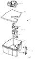
- the arrangement for producing milk froth and for heating milk is provided overall with the reference numeral 1.
- the arrangement 1 essentially comprises a foaming device 2, a milk container 3, a coupling element 4 and a valve arrangement 5.
- a lid 3a for closing the milk container 3 can be seen.
- the foaming device 2 has a lower part 6 and an upper part 7, which two parts 5, 7 are fixable to each other by means of a plug connection.
- a usable from above in the upper part 7 valve insert 8 can be seen, which will be explained in more detail below.
- the milk container 3 is provided with a recess 10, which opens into a slot-shaped recess 11.
- the foaming device 2 in turn is provided with a groove-shaped slot 12, by means of which it can be fixed in the recess 11 of the milk container 3.
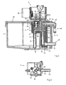
- Fig. 2 From the Fig. 2 is the arrangement according to Fig. 1 in the assembled state in a longitudinal section visible.
- the lower part 6 of the foaming device 2 is tightly connected to the upper part 7, wherein the seals provided for this purpose are not shown in detail.
- the foaming device 2 fixed to the milk container 3 is provided with a steam supply passage 14, an air intake passage 15, a milk supply passage 16 of a discharge port 21, and a vent passage 22. Both the venting channel 22 and the air inlet channel 15 open at the front into the foaming device 2.
- the horizontally extending portion of the milk supply channel 16 is provided with the reference numeral 16a.
- the steam supply channel 14 forms an end Nozzle 23, which opens into a vacuum chamber 24, which connects the milk supply channel 16 with a mixing channel 25.
- the valve insert 8 inserted into the air inlet channel 15 is provided with a check valve 26 in the form of a lip valve.
- the valve assembly 5 On the top of the foaming device 2, the valve assembly 5 is mounted.
- the valve arrangement 5 comprises a silicone mat 28, from the underside of which two closure parts 29, 30 protrude, by means of which the air supply channel 15 as well as the venting channel 22 can be closed at their mouths.
- two elevations 31, 32 arranged corresponding to the closure parts 29, 30 are provided on the upper side of the silicone mat.
- the opening and closing of the valves takes place by means of a camshaft 35 driven by a stepper motor 34.
- the camshaft 35 is provided with a total of three cams 36, 37, 38, by means of which the two closure parts 29, 30 of the silicone mat 28 as well as another on the Back of the valve assembly 5 attached closure body are displaced.
- the closure body 40 is in particular from the illustration according to Fig. 3 seen. In the illustration according to Fig. 2 the vent channel 22 is closed by means of the second closure member 30, while the air supply channel 15 is connected via the open closure member 29 with the ambient air.
- the foaming device 2 is further provided with a trunk-like extension 17 extending in the direction of the bottom of the milk container 3, in which the milk supply channel 16 is arranged and whose distal end has an inlet opening 18 provided with the milk supply channel 16.
- the extension 17 is provided in the region of the inlet opening 18 on both sides, each with a radial recess 19 which favors the inflow of milk from the milk container 3 into the extension 17.
- a cylindrical recess 44 is embedded in the foaming device.
- the discharge opening 21 also opens into a cylindrical recess 45.
- the coupling element 4 is provided with two cylindrical extensions 46, 47, the distance of which corresponds to the distance between the two recesses 44, 45 and whose outer diameter is matched to the diameter of the respective recess 44, 45 in order to form a tight plug connection between the respective extension 46, 47 and the corresponding recess 44, 45 to allow.
- the two cylindrical extensions 46, 47 are connected via a respective bore 50, 51 with a connecting piece 48, 49 in connection.
- the upper connecting piece 48 serves to connect a hose leading to a steam source (not shown), while the lower connecting piece 49 is provided for connecting a hose leading to a beverage outlet (not shown).
- the mode of operation of the arrangement 1 is as follows: In order to froth up milk, the closure part 29 arranged at the inlet of the air inlet channel 15 is opened, while the closure part 30 arranged at the inlet of the ventilation channel 22 is closed. This condition is in the Fig. 2 shown schematically.
- the actuation of the closure parts 29, 30 takes place by activation of the stepping motor 34, which rotates the camshaft 35 into a position in which the respective cam 36, 37 presses the associated elevation 31, 32 downwards. In the illustrated rotational position of the camshaft 35, the cam 37 presses the elevation 32 downwards so that the latter presses the closure part 30 onto the mouth of the venting channel 22 and closes it.
- the mixture of air, milk and steam or water flows into the mixing channel 25, in which a homogeneous milk foam is formed, which exits through the discharge opening 21 from the foaming device 2 and via the bore 51 in the cylindrical extension 47 of the coupling element 4 in the connecting piece 49 flows from where it can flow via unspecified means to the beverage outlet.
- the supply of steam is stopped, whereby the pressure in the vacuum chamber 24 rises and the check valve 26 closes.
- the closure part 30 closing off the venting channel 22 is opened, as a result of which the milk still contained in the frothing device 2 can flow out of it.
- the opening of the closure part 30 is again effected by driving the stepping motor 34, which rotates the camshaft 35 in the corresponding position.
- both the arranged at the entrance of the air inlet channel 15 closure member 29 as well as at the inlet of the Venting channel 22 arranged closure member 30 is closed. Thereafter, steam is again supplied via the steam supply channel 14, which flows via the nozzle 23 into the mixing channel 25.
- the negative pressure caused in the region of the nozzle 23 by the steam flowing through causes milk to be sucked into the milk supply channel 16 via the extension 17, but without air being able to flow via the air inlet channel 15 into the horizontally extending section 16a of the milk supply channel 16. In this way, milk can be heated quickly and easily.
- the closure part 30 arranged at the inlet of the ventilation channel 22 is opened after the respective preparation mode.
- Fig. 3 shows the valve assembly 5 in a cross section. From this illustration, the closure body 40 can be seen, by means of which a through a nozzle 42 leading vent hole 41 can be closed. At the nozzle 42, a vent hose (not shown) can be connected, which is connected by means of a coupling with a beverage line (not shown).
- the closure body 40 is actuated by means of a cam 38 arranged on the cam shaft 35.
- all the channels of the foaming device are provided with a surface formed by nanoparticles which is both hydrophobic and oleophobic and in which at least individual nanoparticles at least partially consist of silver or silver compounds.
- nanoparticles is meant herein particles having a dimension of 10 -10 to 10 -7 m, preferably about 10 -8 m.
Description
- Die Erfindung bezieht sich auf eine gemäss dem Oberbegriff des Anspruchs 1 ausgebildete Anordnung zur Erzeugung von Milchschaum und zum Erhitzen von Milch.
- Zur Erzeugung von Milchschaum sind sogenannte Milchschäumer oder Emulgiereinrichtungen in unterschiedlichen Ausführungsformen bekannt. Diese Milchschäumer bzw. Emulgiereinrichtungen verfügen im allgemeinen über einen Dampfzufuhrkanal, der in eine Saugkammer mündet. Die Saugkammer ihrerseits ist mit einem Milchzufuhrkanal und einem Luftzufuhrkanal verbunden. Durch den Dampfstrom wird in der Saugkammer ein Unterdruck erzeugt, welcher bewirkt, dass Milch über den Milchzufuhrkanal und Luft über den Luftzufuhrkanal in die Saugkammer gesaugt werden. Das erzeugte Dampf-Luft-Milchgemisch wird in einer nachfolgenden Emulgierkammer in eine turbulente Strömung versetzt, so dass ein homogener Milchschaum entsteht. Der mit dem Milchschäumer erzeugte Milchschaum kann beispielsweise für die Herstellung von Cappuccino oder Latte Macchiato verwendet werden. Mit einem Milchschäumer kann neben der Herstellung von Milchschaum im allgemeinen auch Milch erhitzt werden, wobei in diesem Fall die Luftzufuhr unterbrochen wird.
- Aus der
EP 0 195 750 ist eine Emulgiereinrichtung genannte Anordnung zur Erzeugung von Milchschaum bekannt. Diese weist einen Düsenkörper auf, der mit einer Dampferzeuger verbunden wird. Der Düsenkörper ist in einen rohrförmigen Körper eingesetzt, der tangential in eine zylindrische Emulgierkammer mündet. Die Emulgierkammer ist auf der Unterseite mit einer Abgabeöffnung versehen. Im Innern des rohrförmigen Körpers wird eine Saugkammer gebildet, in welche auf der Oberseite ein Lufteinlasskanal und auf der Unterseite ein Milcheinlasskanal mündet. Beim Zuführen von Dampf entsteht in der Saugkammer ein Unterdruck, der das Ansaugen von Milch und Luft bewirkt. Das Gemisch aus Wasser, Dampf, Luft und Milch wird tangential in die Emulgierkammer eingeleitet, in der es in eine turbulente Strömung versetzt wird, welche den Emulgiervorgang fördern und die Kondensation des Dampfes bewirken soll. Über die Abgabeöffnung tritt die erzeugte Emulsion aus der Vorrichtung aus. - Eine weitere Anordnung ist aus der
DE 19955195 A bekannt. - Die Erfindung zielt darauf ab, eine Anordnung zur Erzeugung von Milchschaum und zum Erhitzen von Milch derart weiterzubilden, dass sie einfach aufgebaut ist, und dass die sich nach dem Erzeugen von Milchschaum oder dem Erhitzen von Milch noch in der Schäumvorrichtung befindliche Milch schnell abfliessen kann.
- Hierzu wird nach der Erfindung eine Anordnung gemäss dem Anspruch 1 bereitgestellt.
- Bevorzugte Ausführungsbeispiele der Vorrichtung sind in den abhängigen Ansprüchen 2 bis 20 umschrieben.
- Nachfolgend wird ein Ausführungsbeispiel der Erfindung anhand von Zeichnungen näher erläutert. Dabei zeigt:
-
Fig. 1 die Anordnung zur Erzeugung von Milchschaum und zum Erhitzen von Milch in einer Explosionsdarstellung; -
Fig. 2 einen Längsschnitt durch die Anordnung gemässFig. 1 in zusammengebautem Zustand, und -
Fig. 3 einen Querschnitt durch die Ventilanordnung gemässFig. 2 . - Die Anordnung zur Erzeugung von Milchschaum und zum Erhitzen von Milch ist gesamthaft mit dem Bezugszeichen 1 versehen. Die Anordnung 1 umfasst im wesentlichen eine Schäumvorrichtung 2, einen Milchbehälter 3, ein Kupplungselement 4 sowie eine Ventilanordnung 5. Im weiteren ist ein Deckel 3a zum Verschliessen des Milchbehälters 3 ersichtlich.
- Die Schäumvorrichtung 2 weist einen Unterteil 6 und einen Oberteil 7 auf, welche beiden Teile 5, 7 mittels einer Steckverbindung miteinander fixierbar sind. Im weiteren ist ein von oben in den Oberteil 7 einsetzbarer Ventileinsatz 8 ersichtlich, der anschliessend noch näher erläutert wird. Der Milchbehälter 3 ist mit einer Vertiefung 10 versehen, die in einer schlitzförmigen Ausnehmung 11 mündet. Die Schäumvorrichtung 2 ihrerseits ist mit einem nutförmigen Schlitz 12 versehen, mittels welchem sie in der Ausnehmung 11 des Milchbehälters 3 fixiert werden kann.
- Aus der
Fig. 2 ist die Anordnung gemässFig. 1 im zusammengebauten Zustand in einem Längsschnitt ersichtlich. Der Unterteil 6 der Schäumvorrichtung 2 ist dabei dicht mit dem Oberteil 7 verbunden, wobei die dazu vorgesehenen Dichtungen nicht näher dargestellt sind. Die an dem Milchbehälter 3 fixierte Schäumvorrichtung 2 ist mit einem Dampfzufuhrkanal 14, einem Lufteinlasskanal 15, einem Milchzufuhrkanal 16 einer Abgabeöffnung 21 sowie einem Entlüftungskanal 22 versehen. Sowohl der Entlüftungskanal 22 wie auch der Lufteinlasskanal 15 münden stirnseitig in die Schäumvorrichtung 2. Der horizontal verlaufende Abschnitt des Milchzufuhrkanals 16 ist mit dem Bezugszeichen 16a versehen. Der Dampfzufuhrkanal 14 bildet endseitig eine Düse 23, welche in eine Unterdruckkammer 24 mündet, die den Milchzufuhrkanal 16 mit einem Mischkanal 25 verbindet. Der in den Lufteinlasskanal 15 eingesetzte Ventileinsatz 8 ist mit einem Rückschlagventil 26 in Form eines Lippenventils versehen. - Auf der Oberseite der Schäumvorrichtung 2 ist die Ventilanordnung 5 angebracht. Die Ventilanordnung 5 umfasst eine Silikonmatte 28, von deren Unterseite zwei Verschlussteile 29, 30 vorstehen, mittels welchen der Luftzufuhrkanal 15 wie auch der Entlüftungskanal 22 an deren Mündungen verschliessbar sind. Auf der Oberseite der Silikonmatte sind zwei korrespondierend zu den Verschlussteilen 29, 30 angeordnete Erhebungen 31, 32 angebracht. Das Öffnen und Schliessen der Ventile erfolgt mittels einer von einem Schrittmotor 34 angetriebenen Nockenwelle 35. Die Nockenwelle 35 ist mit insgesamt drei Nocken 36, 37, 38 versehen, mittels welchen die beiden Verschlussteile 29, 30 der Silikonmatte 28 wie auch ein weiterer, auf der Rückseite der Ventilanordnung 5 angebrachter Verschlusskörper verschiebbar sind. Der Verschlusskörper 40 ist insbesondere aus der Darstellung gemäss
Fig. 3 ersichtlich. In der Darstellung gemässFig. 2 ist der Entlüftungskanal 22 mittels des zweiten Verschlussteils 30 geschlossen, während der Luftzufuhrkanal 15 über den geöffneten Verschlussteil 29 mit der Umgebungsluft verbunden ist. - Die Schäumvorrichtung 2 ist im weiteren mit einem sich in Richtung des Bodens des Milchbehälters 3 erstreckenden, rüsselartigen Fortsatz 17 versehen, in welchem der Milchzufuhrkanal 16 angeordnet ist und dessen distales Ende eine mit dem Milchzufuhrkanal 16 versehene Einlassöffnung 18 aufweist. Der Fortsatz 17 ist im Bereich der Einlassöffnung 18 beidseitig mit je einer radialen Ausnehmung 19 versehen, welche das Einströmen der Milch von dem Milchbehälter 3 in den Fortsatz 17 begünstigt. Am Eingang des Dampfzufuhrkanals 8 ist eine zylindrische Ausnehmung 44 in die Schäumvorrichtung eingelassen. Die Abgabeöffnung 21 mündet ebenfalls in eine zylindrische Ausnehmung 45.
- Das Kupplungselement 4 ist mit zwei zylindrischen Fortsätzen 46, 47 versehen, deren Abstand dem Abstand zwischen den beiden Ausnehmungen 44, 45 entspricht und deren Aussendurchmesser auf den Durchmesser der jeweiligen Ausnehmung 44, 45 abgestimmt ist, um eine dichte Steckverbindung zwischen dem jeweiligen Fortsatz 46, 47 und der entsprechenden Ausnehmung 44, 45 zu ermöglichen. Die beiden zylindrischen Fortsätze 46, 47 stehen über je eine Bohrung 50, 51 mit einem Anschlussstutzen 48, 49 in Verbindung. Dabei dient der obere Anschlussstutzen 48 dem Anschlössen eines zu einer Dampfquelle (nicht dargestellt) führenden Schlauchs, während der untere Anschlussstutzen 49 zum Anschliessen eines zu einem Getränkeauslass (nicht dargestellt) führenden Schlauchs vorgesehen ist.
- Die Funktionsweise der Anordnung 1 stellt sich wie folgt dar: Um Milch aufzuschäumen, wird der am Eingang des Lufteinlasskanals 15 angeordnete Verschlussteil 29 geöffnet, während der am Einlass des Entlüftungskanals 22 angeordnete Verschlussteil 30 geschlossen wird. Dieser Zustand ist in der
Fig. 2 schematisch dargestellt. Die Betätigung der Verschlussteile 29, 30 erfolgt durch Ansteuerung des Schrittmotors 34, welcher die Nockenwelle 35 in eine Stellung verdreht, in der der jeweilige Nocken 36, 37 die zugehörige Erhebung 31, 32 nach unten drückt. In der gezeigten Drehstellung der Nockenwelle 35 drückt der Nocken 37 die Erhebung 32 nach unten, so dass letztere den Verschlussteil 30 auf die Mündung des Entlüftungskanals 22 drückt und diesen verschliesst. Nun wird über den Dampfzufuhrkanal 14 Dampf zugeführt, der über die Düse 23 in den Mischkanal 25 einströmt und in der Unterdruckkammer 24 einen Unterdruck erzeugt. Dieser Unterdruck führt dazu, dass einerseits über den Fortsatz 17 Milch in den Milchzufuhrkanal 16 eingesaugt wird. Andererseits bewirkt der Unterdruck ein Öffnen des im Lufteinlasskanals 15 angeordneten Rückschlagventils 26, so dass Luft über den Lufteinlasskanal 15 in den horizontal verlaufenden Abschnitt 16a des Milchzufuhrkanals 16 einströmt. Die über den Lufteinlasskanal 15 einströmende Luft vermischt sich mit der durchströmenden Milch. Nach der Düse 23 vermischt sich die Milch mit dem Dampf, welcher letzterer dabei sogleich kondensiert. Durch das Kondensieren des Dampfs wird die Sogwirkung im Bereich der Düse 23 unterstützt. Das Gemisch aus Luft, Milch und Dampf bzw. Wasser strömt in den Mischkanal 25 ein, in welchem ein homogener Milchschaum entsteht, der über die Abgabeöffnung 21 aus der Schäumvorrichtung 2 austritt und über die Bohrung 51 im zylindrischen Fortsatz 47 des Kupplungselements 4 in den Anschlussstutzen 49 einströmt, von wo er über nicht näher dargestellte Mittel zu dem Getränkeauslass strömen kann. - Zum Beenden des Aufschäumvorgangs wird die Zufuhr von Dampf gestoppt, wodurch auch der Druck in der Unterdruckkammer 24 ansteigt und das Rückschlagventil 26 schliesst. Nach dem Aufschäumen von Milch wird der den Entlüftungskanal 22 verschliessende Verschlussteil 30 geöffnet, wodurch die sich noch der Schäumvorrichtung 2 befindliche Milch daraus abfliessen kann. Das Öffnen des Verschlussteils 30 erfolgt wiederum durch Ansteuerung des Schrittmotors 34, der die Nockenwelle 35 in die entsprechende Position verdreht. Durch das Entlüften der Schäumvorrichtung 2 kann gleichzeitig auch verhindert werden, dass in dem Falle, wo der Milchauslauf unterhalb des Milchbehälters 3 angeordnet ist, weiterhin Milch nach dem Prinzip der kommunizierenden Röhren aus dem Milchbehälter 3 abfliesst.
- Zum Erwärmen bzw. Erhitzen von Milch, wird sowohl der am Eingang des Lufteinlasskanals 15 angeordnete Verschlussteil 29 wie auch der am Einlass des Entlüftungskanals 22 angeordnete Verschlussteil 30 geschlossen. Danach wird wiederum über den Dampfzufuhrkanal 14 Dampf zugeführt, der über die Düse 23 in den Mischkanal 25 einströmt. Der im Bereich der Düse 23 durch den durchströmenden Dampf bewirkte Unterdruck führt dazu, dass über den Fortsatz 17 Milch in den Milchzufuhrkanal 16 eingesaugt wird, ohne dass jedoch Luft über den Lufteinlasskanal 15 in den horizontal verlaufenden Abschnitt 16a des Milchzufuhrkanals 16 einströmen kann. Auf diese Weise kann Milch schnell und einfach erhitzt werden.
- Um ein Entleeren der milchführenden Leitungsteile, Bohrungen und Kanäle 16, 16a, 24, 25, 51 nach dem jeweiligen Schäum- bzw. Erhitzungsvorgang sicherzustellen, wird der am Einlass des Entlüftungskanals 22 angeordnete Verschlussteil 30 nach dem jeweiligen Zubereitungsmodus geöffnet.
-
Fig. 3 zeigt die Ventilanordnung 5 in einem Querschnitt. Aus dieser Darstellung ist der Verschlusskörper 40 ersichtlich, mittels welchem eine durch einen Stutzen 42 führende Entlüftungsbohrung 41 verschliessbar ist. Am Stutzen 42 ist ein Entlüftungsschlauch (nicht dargestellt) anschliessbar, der mittels einer Kupplung mit einer Getränkeleitung (nicht dargestellt) verbunden ist. Der Verschlusskörper 40 wird mittels eines an der Nockenwelle 35 angeordneten Nockens 38 betätigt. - Vorzugsweise sind sämtliche Kanäle der Schäumvorrichtung mit einer durch Nano-Partikel gebildeten Oberfläche versehen, die sowohl hydrophob wie auch oleophob ist und bei der zumindest einzelne Nano-Partikel zum Mindesten teilweise aus Silber oder Silberverbindungen bestehen. Durch das Vorsehen einer solchen Oberfläche ist die Schäumvorrichtung leicht zu reinigen und besitzt zusätzlich eine antimikrobielle Wirksamkeit. Unter "Nano-Partikel" werden hier Teilchen mit einer Abmessung von10-10 bis 10-7 m, vorzugsweise von etwa 10-8 m, verstanden.
- Trotz der relativen Schmutzunempfindlichkeit der Anordnung, sollte diese regelmässig gereinigt werden. Dies kann entweder mittels eines Spülprogramms erfolgen, bei welchem zumindest die verschmutzungskritischen Leitungsteile, Bohrungen und Kanäle 16, 21, 24, 25, 45, 51 mit heissem Wasser durchgespült werden. Eine andere Variante besteht darin, das Kupplungselement 4 manuell von der Schäumvorrichtung 2 zu entfernen und die Schäumvorrichtung 2 von dem Milchbehälter 3 abzuheben. Danach kann der Oberteil 7 der Schäumvorrichtung 2 von dem Unterteil 6 abgezogen werden, wodurch die verschmutzungskritischen Innenteile der Schäumvorrichtung 2, insbesondere der horizontale Abschnitt 16 a des Milchzufuhrkanals sowie die Düse 23 und die Unterdruckkammer 24 freigelegt werden. Ebenso kann der Ventileinsatz 9 entfernt werden. Die genannten Bauteile können dann beispielsweise in einem Geschirrspüler gereinigt werden.
Claims (21)
- Anordnung (1) zur Erzeugung von Milchschaum und zum Erhitzen von Milch, mit einer Schäumvorrichtung (2), welche mit einem Dampfzufuhrkanal (14), einem Lufteinlasskanal (15), einem Milchzufuhrkanal (16) sowie einer Abgabeöffnung (21) versehen ist, dadurch gekennzeichnet, dass die Schäumvorrichtung (2) einen Entlüftungskanal (22) aufweist, mittels welchem die Schäumvorrichtung (2) nach dem Erzeugen von Milchschaum oder dem Erhitzen von Milch entlüftet werden kann, und dass eine Ventilanordnung (5) vorgesehen ist, mittels welcher der Entlüftungskanal (22) und/oder der Lufteinlasskanal (15) in Abhängigkeit der gewünschten Betriebsart verschliessbar ist.
- Anordnung (1) nach Anspruch 1, dadurch gekennzeichnet, dass die Ventilanordnung (5) mit einem ersten Verschlussteil (29) zum Verschliessen des Lufteinlasskanals (15) und einem zweiten Verschlussteil (30) zum Verschliessen des Entlüftungskanals (22) versehen ist.
- Anordnung (1) nach Anspruch 1 oder 2, dadurch gekennzeichnet, dass die Ventilanordnung (5) mit einem Verschlusskörper (40) zum Verschliessen bzw. Entlüften einer mit einer Getränkeleitung verbundenen Entlüftungsbohrung (41) versehen ist.
- Anordnung (1) nach einem der vorhergehenden Ansprüche, dadurch gekennzeichnet, dass die Ventilanordnung (5) elektromotorisch, elektromagnetisch, hydraulisch oder pneumatisch betätigbar ist.
- Anordnung (1) nach einem der Ansprüche 2, 3 oder 4, dadurch gekennzeichnet, dass die Ventilanordnung (5) einen Schrittmotor (34) und eine mit diesem gekoppelte Nockenwelle (35) aufweist, deren Nocken zum Betätigen der Verschlussteile (29, 30) und/oder des Verschlusskörpers (40) ausgebildet ist.
- Anordnung (1) nach einem der vorhergehenden Ansprüche, dadurch gekennzeichnet, dass sowohl der Entlüftungskanal (22) wie auch der Lufteinlasskanal (15) stirnseitig in die Schäumvorrichtung (2) münden, und dass über den beiden Mündungen eine Silikonmatte (28) angeordnet ist, welche mit zwei Verschlussteilen (29, 30) zum Verschliessen des Entlüftungskanals (22) bzw. des Lufteinlasskanals (15) versehen ist, wobei die beiden Verschlussteile (29, 30) mittels einer elektromotorisch angetriebenen Nockenwelle (35) betätigbar sind.
- Anordnung (1) nach Anspruch 3, dadurch gekennzeichnet, dass der Verschlusskörper (40) mittels einer elektromotorisch angetriebenen Nockenwelle (35) betätigbar.
- Anordnung (1) nach einem der vorhergehenden Ansprüche, dadurch gekennzeichnet, dass der Dampfzufuhrkanal (14) über eine Düse (23) in eine Unterdruckkammer (24) mündet, welche einlassseitig mit dem Milchzufuhrkanal (16a) und auslassseitig mit einem Mischkanal (25) verbunden ist.
- Anordnung (1) nach einem der vorhergehenden Ansprüche, dadurch gekennzeichnet, dass der Entlüftungskanal (22) mit dem Milchzufuhrkanal (16a) verbunden ist.
- Anordnung (1) nach einem der vorhergehenden Ansprüche, dadurch gekennzeichnet, dass im Lufteinlasskanal (15) ein Rückschlagventil (26) angeordnet ist, welches bei geöffnetem erstem Verschlussteil (29) und einem vorbestimmten, durch die Zufuhr von Dampf in einer Unterdruckkammer (24) erzeugten Unterdruck öffnet.
- Anordnung (1) nach einem der vorhergehenden Ansprüche, dadurch gekennzeichnet, dass die Anordnung (1) im weiteren einen Milchbehälter (3) umfasst, an dem die Schäumvorrichtung (2) lösbar fixiert ist.
- Anordnung (1) nach Anspruch 11, dadurch gekennzeichnet, dass die Schäumvorrichtung (2) mit einem sich in Richtung des Bodens des Milchbehälters (3) erstreckenden Fortsatz (17) versehen ist, in welchem der Milchzufuhrkanal (16) angeordnet ist und dessen distales Ende mit einer mit dem Milchzufuhrkanal (16) verbundenen Einlassöffnung (18) versehen ist.
- Anordnung (1) nach Anspruch 12, dadurch gekennzeichnet, dass der Fortsatz (17) im Bereich der Einlassöffnung (18) mit zumindest einer radialen Ausnehmung (19) versehen ist.
- Anordnung (1) nach einem der vorhergehenden Ansprüche, dadurch gekennzeichnet, dass die Schäumvorrichtung (2) mehrteilig ausgebildet ist und die einzelnen Teile (6, 7, 8) mittels einer Steck- oder Schnappverbindung miteinander verbindbar sind.
- Anordnung (1) nach Anspruch 13, dadurch gekennzeichnet, dass der Milchzufuhrkanal (11) nach dem Trennen der einzelnen Teile (6, 7, 8) zumindest teilweise freigelegt ist.
- Anordnung (1) nach einem der vorhergehenden Ansprüche, dadurch gekennzeichnet, dass die Schäumvorrichtung (2) eine erste zylindrische Ausnehmung (44) aufweist, welche mit dem Dampfzufuhrkanal (14) verbunden ist.
- Anordnung (1) nach einem der vorhergehenden Ansprüche, dadurch gekennzeichnet, dass die Schäumvorrichtung (2) eine zweite zylindrische Ausnehmung (45) aufweist, welche mit der Abgabeöffnung (21) verbunden ist oder diese bildet.
- Anordnung (1) nach Anspruch 16 und 17, dadurch gekennzeichnet, dass die Schäumvorrichtung (2) ein Kupplungselement (4) aufweist, welches mit zwei zylindrischen Fortsätzen (46, 47) versehen ist, welche zum Ankuppeln an die erste und zweite zylindrische Ausnehmung (45, 46) ausgebildet sind, wobei am einen Fortsatz (46) eine Dampfzufuhrleitung anschliessbar ist und wobei am weiteren Fortsatz (47) eine Abgabeleitung anschliessbar ist.
- Anordnung (1) nach einem der vorhergehenden Ansprüche, dadurch gekennzeichnet, dass zumindest der Dampfzufuhrkanal (14), der Lufteinlasskanal (15), der Milchzufuhrkanal (16), die Düse (23) und die Unterdruckkammer (24) der Schäumvorrichtung (2) mit einer durch Nano-Partikel gebildeten hydrophoben und oleophoben Oberfläche versehen ist, deren Nano-Partikel zum Mindesten teilweise aus Silber oder Silberverbindungen bestehen.
- Anordnung (1) nach einem der vorhergehenden Ansprüche, dadurch gekennzeichnet, dass sie zusammen mit einer Espressokaffeemaschine verwendet wird oder dass sie in einer Espressokaffeemaschine zum Einsatz kommt.
- Espressokaffeemaschine mit einer nach einem der Ansprüche 1 bis 19 ausgebildeten Anordnung (1).
Applications Claiming Priority (1)
| Application Number | Priority Date | Filing Date | Title |
|---|---|---|---|
| CH1942005 | 2005-02-08 |
Publications (2)
| Publication Number | Publication Date |
|---|---|
| EP1688074A1 EP1688074A1 (de) | 2006-08-09 |
| EP1688074B1 true EP1688074B1 (de) | 2008-03-19 |
Family
ID=34980113
Family Applications (1)
| Application Number | Title | Priority Date | Filing Date |
|---|---|---|---|
| EP06405040A Active EP1688074B1 (de) | 2005-02-08 | 2006-01-30 | Anordnung zur Erzeugung von Milchschaum und zum Erhitzen von Milch |
Country Status (13)
| Country | Link |
|---|---|
| US (1) | US20060174771A1 (de) |
| EP (1) | EP1688074B1 (de) |
| KR (1) | KR20060090591A (de) |
| CN (1) | CN1817280B (de) |
| AT (1) | ATE389347T1 (de) |
| AU (1) | AU2006200530B2 (de) |
| BR (1) | BRPI0600251A (de) |
| DE (1) | DE502006000460D1 (de) |
| ES (1) | ES2302564T3 (de) |
| HK (1) | HK1092667A1 (de) |
| MX (1) | MXPA06001534A (de) |
| RU (1) | RU2006103558A (de) |
| TW (1) | TWI369963B (de) |
Cited By (2)
| Publication number | Priority date | Publication date | Assignee | Title |
|---|---|---|---|---|
| EP2220973A1 (de) | 2009-02-24 | 2010-08-25 | Jura Elektroapparate AG | Abgabevorrichtung für Milch und/oder Milchschaum und eine Kaffeemaschine mit einer derartigen Abgabevorrichtung |
| EP2277419A1 (de) | 2009-07-23 | 2011-01-26 | WMF Württembergische Metallwarenfabrik AG | Getränkeautomat |
Families Citing this family (17)
| Publication number | Priority date | Publication date | Assignee | Title |
|---|---|---|---|---|
| ITFI20060263A1 (it) | 2006-10-27 | 2008-04-28 | Saeco Ipr Ltd | Dispositivo emulsionatore per la produzione di latte schiumato e simili e relativo metodo |
| AT504103B1 (de) * | 2007-02-21 | 2008-03-15 | Kupfner Franz | Kaffeemaschine |
| US8131137B1 (en) * | 2008-03-24 | 2012-03-06 | Cowles Scott R | Baby bottle steamer |
| ITFI20080198A1 (it) | 2008-10-15 | 2010-04-16 | Saeco Ipr Ltd | "macchina da caffe'" |
| EP2245969A1 (de) | 2009-04-30 | 2010-11-03 | Jura Elektroapparate AG | Andocksystem für einen Milchbehälter |
| EP2253253A1 (de) * | 2009-05-18 | 2010-11-24 | Jura Elektroapparate AG | Getränkebereitungsmaschine |
| DE102010012562A1 (de) * | 2010-03-23 | 2010-09-23 | SEVERIN ELEKTROGERÄTE GmbH | Elektrische Getränkezubereitungsmaschine |
| CN104379034B (zh) | 2012-10-26 | 2018-12-25 | 皇家飞利浦有限公司 | 包括用于输送液体的至少一个管的饮料制作设备 |
| US9060647B2 (en) | 2012-11-02 | 2015-06-23 | Whirlpool Corporation | Frothing device for an espresso machine |
| JP5944609B1 (ja) * | 2013-04-02 | 2016-07-05 | コーニンクレッカ フィリップス エヌ ヴェKoninklijke Philips N.V. | 水差し及び該水差しを有する飲料製造機 |
| EP2944237A1 (de) * | 2014-05-14 | 2015-11-18 | Jura Elektroapparate Ag | Auslaufeinrichtung für eine Milchschäumvorrichtung |
| EP3000365A1 (de) * | 2014-09-24 | 2016-03-30 | Qbo Coffee GmbH | Milchschäumergerät |
| EP3000363A1 (de) | 2014-09-24 | 2016-03-30 | Qbo Coffee GmbH | Milchschäumergerät, Getränkezubereitungssystem und Getränkezubereitungsmaschine |
| EP3000362A1 (de) * | 2014-09-24 | 2016-03-30 | Qbo Coffee GmbH | Milchschäumergerät, Getränkezubereitungssystem und Getränkezubereitungsmaschine |
| EP3000364A1 (de) * | 2014-09-24 | 2016-03-30 | Qbo Coffee GmbH | Milchschäumergerät |
| ITUB20159657A1 (it) * | 2015-12-17 | 2017-06-17 | Caffitaly System Spa | Apparecchiatura per la preparazione di una bevanda, in particolare per una bevanda contenente latte |
| CN108175282A (zh) * | 2018-02-09 | 2018-06-19 | 上海宝路通咖啡机有限公司 | 全自动咖啡机的奶泡器及全自动咖啡机 |
Family Cites Families (12)
| Publication number | Priority date | Publication date | Assignee | Title |
|---|---|---|---|---|
| IT1177590B (it) * | 1984-03-08 | 1987-08-26 | Mario Chiaro | Dispositivo per la preparazione di latte caldo schiumoso |
| ES8700918A1 (es) | 1985-01-31 | 1986-11-16 | Spidem Srl | Perfeccionamientos en los dispositivos emulsionadores |
| NL1002936C2 (nl) * | 1996-04-24 | 1997-10-28 | Sara Lee De Nv | Samenstel voor het bereiden van warme en geschuimde melk. |
| US6006654A (en) * | 1997-06-13 | 1999-12-28 | Tcc Trading Limited | Milk frothing apparatus and method |
| DE19945977A1 (de) * | 1999-09-24 | 2001-04-05 | Braun Gmbh | Dampferzeugungseinrichtung zum Aufwärmen und/oder Aufschäumen von Flüssigkeiten, insbesondere Milch und Verfahren hierzu |
| DE19955195B4 (de) * | 1999-11-16 | 2005-07-07 | Niro-Plan Ag | Vorrichtung zum Aufschäumen von Milch |
| US6405637B1 (en) * | 2000-01-13 | 2002-06-18 | Houseware Technology Group Llc | Fluid delivery system for generating pressure pulses to make beverages |
| US6289796B1 (en) * | 2001-02-23 | 2001-09-18 | Simatelex Manufactory Company Limited | Hot milk dispenser |
| EP1312292B1 (de) * | 2001-11-14 | 2004-04-28 | Cafina AG | Anordnung zur Erzeugung von Milchschaum und zum Erhitzen von Milch |
| US7021206B2 (en) * | 2002-06-18 | 2006-04-04 | Eckenhausen Roland B | Hot dairy-based beverage dispenser |
| US6977091B2 (en) * | 2002-10-11 | 2005-12-20 | Nestec S.A. | Froth showering |
| US6959642B1 (en) * | 2004-04-07 | 2005-11-01 | Egro Ag | Device for portioned delivery of milk, particularly for cappuccino machines |
-
2006
- 2006-01-30 AT AT06405040T patent/ATE389347T1/de active
- 2006-01-30 DE DE502006000460T patent/DE502006000460D1/de active Active
- 2006-01-30 EP EP06405040A patent/EP1688074B1/de active Active
- 2006-01-30 ES ES06405040T patent/ES2302564T3/es active Active
- 2006-02-01 US US11/345,442 patent/US20060174771A1/en not_active Abandoned
- 2006-02-07 BR BRPI0600251-0A patent/BRPI0600251A/pt not_active IP Right Cessation
- 2006-02-07 RU RU2006103558/12A patent/RU2006103558A/ru not_active Application Discontinuation
- 2006-02-07 KR KR1020060011371A patent/KR20060090591A/ko not_active Application Discontinuation
- 2006-02-07 TW TW095104042A patent/TWI369963B/zh not_active IP Right Cessation
- 2006-02-08 MX MXPA06001534A patent/MXPA06001534A/es active IP Right Grant
- 2006-02-08 AU AU2006200530A patent/AU2006200530B2/en not_active Ceased
- 2006-02-08 CN CN2006100064723A patent/CN1817280B/zh active Active
- 2006-12-12 HK HK06113634.9A patent/HK1092667A1/xx not_active IP Right Cessation
Cited By (5)
| Publication number | Priority date | Publication date | Assignee | Title |
|---|---|---|---|---|
| EP2220973A1 (de) | 2009-02-24 | 2010-08-25 | Jura Elektroapparate AG | Abgabevorrichtung für Milch und/oder Milchschaum und eine Kaffeemaschine mit einer derartigen Abgabevorrichtung |
| EP2220972A1 (de) | 2009-02-24 | 2010-08-25 | Jura Elektroapparate AG | Abgabevorrichtung für Milch und/oder Milchschaum und eine Kaffeemaschine mit einer derartigen Abgabevorrichtung |
| EP2277419A1 (de) | 2009-07-23 | 2011-01-26 | WMF Württembergische Metallwarenfabrik AG | Getränkeautomat |
| DE102009034234A1 (de) | 2009-07-23 | 2011-04-07 | Wmf Württembergische Metallwarenfabrik Ag | Getränkeautomat |
| DE102009034234B4 (de) * | 2009-07-23 | 2013-06-13 | Wmf Württembergische Metallwarenfabrik Ag | Getränkeautomat |
Also Published As
| Publication number | Publication date |
|---|---|
| EP1688074A1 (de) | 2006-08-09 |
| RU2006103558A (ru) | 2007-08-20 |
| HK1092667A1 (en) | 2007-02-16 |
| KR20060090591A (ko) | 2006-08-14 |
| AU2006200530B2 (en) | 2011-10-27 |
| BRPI0600251A (pt) | 2006-10-03 |
| MXPA06001534A (es) | 2006-09-26 |
| CN1817280A (zh) | 2006-08-16 |
| TWI369963B (en) | 2012-08-11 |
| ATE389347T1 (de) | 2008-04-15 |
| AU2006200530A1 (en) | 2006-08-24 |
| TW200635550A (en) | 2006-10-16 |
| CN1817280B (zh) | 2010-12-29 |
| DE502006000460D1 (de) | 2008-04-30 |
| ES2302564T3 (es) | 2008-07-16 |
| US20060174771A1 (en) | 2006-08-10 |
Similar Documents
| Publication | Publication Date | Title |
|---|---|---|
| EP1688074B1 (de) | Anordnung zur Erzeugung von Milchschaum und zum Erhitzen von Milch | |
| EP1688075B1 (de) | Anordnung zur Erzeugung von Milchschaum und/oder zum Erhitzen von Milch | |
| EP2353472B1 (de) | Kaffeemaschine mit einer Schäumvorrichtung und Mitteln zum Reinigen der Schäumvorrichtung | |
| EP1312292B1 (de) | Anordnung zur Erzeugung von Milchschaum und zum Erhitzen von Milch | |
| DE102008058139B4 (de) | Aufschäumeinheit zum Aufschäumen von Milch und Anordnung enthaltend eine solche Aufschäumeinheit | |
| EP0374637B1 (de) | Vorrichtung zum Zubereiten von Cappuccino | |
| DE602005004558T2 (de) | Automatische Vorrichtung zum Erhitzen und Schäumen von Milch | |
| DE69733675T2 (de) | Vorrichtung zur Zubereitung von heisser Milch und Schaummilch | |
| DE4445436C2 (de) | Aufschäumvorrichtung | |
| DE60119516T2 (de) | Automatische vorrichtung zum erhitzen und aufschäumen einer flüssigkeit, insbesondere milch | |
| EP3079538B1 (de) | Milchschäumergerät, getränkezubereitungssystem und getränkezubereitungsmaschine | |
| EP0662297A1 (de) | Vorrichtung zur Zubereitung von Milchschaum für Cappuccino | |
| EP0600826B1 (de) | Vorrichtung zur Erzeugung von Milchschaum für Cappuccino-Kaffee oder ähnlichen Getränken | |
| EP2589322A1 (de) | Kaffeemaschine, insbesondere Espressovollautomat | |
| EP2277419B1 (de) | Getränkeautomat | |
| DE202009014114U1 (de) | Vorrichtung zur Zubereitung eines milchbasierten Getränks | |
| EP3000363A1 (de) | Milchschäumergerät, Getränkezubereitungssystem und Getränkezubereitungsmaschine | |
| EP1857028B1 (de) | Milchaufschäumdüse | |
| EP2807964B1 (de) | Milchaufschäumvorrichtung, Kaffeemaschine, System sowie Reinigungsverfahren | |
| EP2730201B1 (de) | Milchaufschäumvorrichtung zum Betreiben mit einer Kaffeemaschine sowie Kaffeemaschine | |
| EP2236061A1 (de) | Getränkeautomat | |
| EP3045091B1 (de) | Getränkezubereitungsvorrichtung sowie betriebsverfahren | |
| DE102005010599A1 (de) | Vorrichtung zum Aufschäumen von Milch mit externer Milchansaugung und direkter Ankoppelung an die Dampfzuleitung | |
| DE102011006483A1 (de) | Milchleitungsspülsystem | |
| DE102010028729A1 (de) | Milchschäumer mit Rückflusssperre |
Legal Events
| Date | Code | Title | Description |
|---|---|---|---|
| PUAI | Public reference made under article 153(3) epc to a published international application that has entered the european phase |
Free format text: ORIGINAL CODE: 0009012 |
|
| AK | Designated contracting states |
Kind code of ref document: A1 Designated state(s): AT BE BG CH CY CZ DE DK EE ES FI FR GB GR HU IE IS IT LI LT LU LV MC NL PL PT RO SE SI SK TR |
|
| AX | Request for extension of the european patent |
Extension state: AL BA HR MK YU |
|
| 17P | Request for examination filed |
Effective date: 20060819 |
|
| AKX | Designation fees paid |
Designated state(s): AT BE BG CH CY CZ DE DK EE ES FI FR GB GR HU IE IS IT LI LT LU LV MC NL PL PT RO SE SI SK TR |
|
| GRAP | Despatch of communication of intention to grant a patent |
Free format text: ORIGINAL CODE: EPIDOSNIGR1 |
|
| GRAS | Grant fee paid |
Free format text: ORIGINAL CODE: EPIDOSNIGR3 |
|
| GRAA | (expected) grant |
Free format text: ORIGINAL CODE: 0009210 |
|
| AK | Designated contracting states |
Kind code of ref document: B1 Designated state(s): AT BE BG CH CY CZ DE DK EE ES FI FR GB GR HU IE IS IT LI LT LU LV MC NL PL PT RO SE SI SK TR |
|
| REG | Reference to a national code |
Ref country code: GB Ref legal event code: FG4D Free format text: NOT ENGLISH |
|
| REG | Reference to a national code |
Ref country code: CH Ref legal event code: EP Ref country code: CH Ref legal event code: NV Representative=s name: ROTTMANN, ZIMMERMANN + PARTNER AG |
|
| REF | Corresponds to: |
Ref document number: 502006000460 Country of ref document: DE Date of ref document: 20080430 Kind code of ref document: P |
|
| REG | Reference to a national code |
Ref country code: IE Ref legal event code: FG4D Free format text: LANGUAGE OF EP DOCUMENT: GERMAN |
|
| REG | Reference to a national code |
Ref country code: ES Ref legal event code: FG2A Ref document number: 2302564 Country of ref document: ES Kind code of ref document: T3 |
|
| PG25 | Lapsed in a contracting state [announced via postgrant information from national office to epo] |
Ref country code: LT Free format text: LAPSE BECAUSE OF FAILURE TO SUBMIT A TRANSLATION OF THE DESCRIPTION OR TO PAY THE FEE WITHIN THE PRESCRIBED TIME-LIMIT Effective date: 20080319 Ref country code: FI Free format text: LAPSE BECAUSE OF FAILURE TO SUBMIT A TRANSLATION OF THE DESCRIPTION OR TO PAY THE FEE WITHIN THE PRESCRIBED TIME-LIMIT Effective date: 20080319 |
|
| NLV1 | Nl: lapsed or annulled due to failure to fulfill the requirements of art. 29p and 29m of the patents act | ||
| PG25 | Lapsed in a contracting state [announced via postgrant information from national office to epo] |
Ref country code: SI Free format text: LAPSE BECAUSE OF FAILURE TO SUBMIT A TRANSLATION OF THE DESCRIPTION OR TO PAY THE FEE WITHIN THE PRESCRIBED TIME-LIMIT Effective date: 20080319 Ref country code: PL Free format text: LAPSE BECAUSE OF FAILURE TO SUBMIT A TRANSLATION OF THE DESCRIPTION OR TO PAY THE FEE WITHIN THE PRESCRIBED TIME-LIMIT Effective date: 20080319 Ref country code: LV Free format text: LAPSE BECAUSE OF FAILURE TO SUBMIT A TRANSLATION OF THE DESCRIPTION OR TO PAY THE FEE WITHIN THE PRESCRIBED TIME-LIMIT Effective date: 20080319 |
|
| ET | Fr: translation filed | ||
| REG | Reference to a national code |
Ref country code: IE Ref legal event code: FD4D |
|
| PG25 | Lapsed in a contracting state [announced via postgrant information from national office to epo] |
Ref country code: SK Free format text: LAPSE BECAUSE OF FAILURE TO SUBMIT A TRANSLATION OF THE DESCRIPTION OR TO PAY THE FEE WITHIN THE PRESCRIBED TIME-LIMIT Effective date: 20080319 Ref country code: PT Free format text: LAPSE BECAUSE OF FAILURE TO SUBMIT A TRANSLATION OF THE DESCRIPTION OR TO PAY THE FEE WITHIN THE PRESCRIBED TIME-LIMIT Effective date: 20080826 Ref country code: CZ Free format text: LAPSE BECAUSE OF FAILURE TO SUBMIT A TRANSLATION OF THE DESCRIPTION OR TO PAY THE FEE WITHIN THE PRESCRIBED TIME-LIMIT Effective date: 20080319 Ref country code: SE Free format text: LAPSE BECAUSE OF FAILURE TO SUBMIT A TRANSLATION OF THE DESCRIPTION OR TO PAY THE FEE WITHIN THE PRESCRIBED TIME-LIMIT Effective date: 20080619 |
|
| PG25 | Lapsed in a contracting state [announced via postgrant information from national office to epo] |
Ref country code: NL Free format text: LAPSE BECAUSE OF FAILURE TO SUBMIT A TRANSLATION OF THE DESCRIPTION OR TO PAY THE FEE WITHIN THE PRESCRIBED TIME-LIMIT Effective date: 20080319 Ref country code: RO Free format text: LAPSE BECAUSE OF FAILURE TO SUBMIT A TRANSLATION OF THE DESCRIPTION OR TO PAY THE FEE WITHIN THE PRESCRIBED TIME-LIMIT Effective date: 20080319 |
|
| PG25 | Lapsed in a contracting state [announced via postgrant information from national office to epo] |
Ref country code: IS Free format text: LAPSE BECAUSE OF FAILURE TO SUBMIT A TRANSLATION OF THE DESCRIPTION OR TO PAY THE FEE WITHIN THE PRESCRIBED TIME-LIMIT Effective date: 20080719 |
|
| PLBE | No opposition filed within time limit |
Free format text: ORIGINAL CODE: 0009261 |
|
| STAA | Information on the status of an ep patent application or granted ep patent |
Free format text: STATUS: NO OPPOSITION FILED WITHIN TIME LIMIT |
|
| PG25 | Lapsed in a contracting state [announced via postgrant information from national office to epo] |
Ref country code: IE Free format text: LAPSE BECAUSE OF FAILURE TO SUBMIT A TRANSLATION OF THE DESCRIPTION OR TO PAY THE FEE WITHIN THE PRESCRIBED TIME-LIMIT Effective date: 20080319 Ref country code: DK Free format text: LAPSE BECAUSE OF FAILURE TO SUBMIT A TRANSLATION OF THE DESCRIPTION OR TO PAY THE FEE WITHIN THE PRESCRIBED TIME-LIMIT Effective date: 20080319 |
|
| 26N | No opposition filed |
Effective date: 20081222 |
|
| PG25 | Lapsed in a contracting state [announced via postgrant information from national office to epo] |
Ref country code: BG Free format text: LAPSE BECAUSE OF FAILURE TO SUBMIT A TRANSLATION OF THE DESCRIPTION OR TO PAY THE FEE WITHIN THE PRESCRIBED TIME-LIMIT Effective date: 20080619 Ref country code: EE Free format text: LAPSE BECAUSE OF FAILURE TO SUBMIT A TRANSLATION OF THE DESCRIPTION OR TO PAY THE FEE WITHIN THE PRESCRIBED TIME-LIMIT Effective date: 20080319 |
|
| PG25 | Lapsed in a contracting state [announced via postgrant information from national office to epo] |
Ref country code: MC Free format text: LAPSE BECAUSE OF NON-PAYMENT OF DUE FEES Effective date: 20090131 |
|
| PG25 | Lapsed in a contracting state [announced via postgrant information from national office to epo] |
Ref country code: CY Free format text: LAPSE BECAUSE OF FAILURE TO SUBMIT A TRANSLATION OF THE DESCRIPTION OR TO PAY THE FEE WITHIN THE PRESCRIBED TIME-LIMIT Effective date: 20080319 |
|
| PG25 | Lapsed in a contracting state [announced via postgrant information from national office to epo] |
Ref country code: BE Free format text: LAPSE BECAUSE OF NON-PAYMENT OF DUE FEES Effective date: 20090131 |
|
| PG25 | Lapsed in a contracting state [announced via postgrant information from national office to epo] |
Ref country code: GR Free format text: LAPSE BECAUSE OF FAILURE TO SUBMIT A TRANSLATION OF THE DESCRIPTION OR TO PAY THE FEE WITHIN THE PRESCRIBED TIME-LIMIT Effective date: 20080620 |
|
| REG | Reference to a national code |
Ref country code: CH Ref legal event code: PUE Owner name: KONINKLIJKE PHILIPS ELECTRONICS N.V. Free format text: SAECO IPR LIMITED#UNIT 1E, BLOCK 71 PARK WEST BUSINESS PARK NANGOR ROAD#DUBLIN 12 (IE) -TRANSFER TO- KONINKLIJKE PHILIPS ELECTRONICS N.V.#GROENEWOUDSEWEG 1#5621 BA EINDHOVEN (NL) Ref country code: CH Ref legal event code: NV Representative=s name: JACOBACCI & PARTNERS S.P.A. |
|
| REG | Reference to a national code |
Ref country code: GB Ref legal event code: 732E Free format text: REGISTERED BETWEEN 20110113 AND 20110119 |
|
| REG | Reference to a national code |
Ref country code: FR Ref legal event code: TP |
|
| PG25 | Lapsed in a contracting state [announced via postgrant information from national office to epo] |
Ref country code: LU Free format text: LAPSE BECAUSE OF NON-PAYMENT OF DUE FEES Effective date: 20090130 |
|
| PG25 | Lapsed in a contracting state [announced via postgrant information from national office to epo] |
Ref country code: HU Free format text: LAPSE BECAUSE OF FAILURE TO SUBMIT A TRANSLATION OF THE DESCRIPTION OR TO PAY THE FEE WITHIN THE PRESCRIBED TIME-LIMIT Effective date: 20080920 |
|
| REG | Reference to a national code |
Ref country code: ES Ref legal event code: PC2A Owner name: KONINKLIJKE PHILIPS ELECTRONICS N.V. Effective date: 20110804 |
|
| REG | Reference to a national code |
Ref country code: FR Ref legal event code: ST Effective date: 20110930 |
|
| PG25 | Lapsed in a contracting state [announced via postgrant information from national office to epo] |
Ref country code: FR Free format text: LAPSE BECAUSE OF NON-PAYMENT OF DUE FEES Effective date: 20110131 |
|
| REG | Reference to a national code |
Ref country code: FR Ref legal event code: RN Effective date: 20111205 |
|
| REG | Reference to a national code |
Ref country code: FR Ref legal event code: FC Effective date: 20111219 |
|
| REG | Reference to a national code |
Ref country code: DE Ref legal event code: R082 Ref document number: 502006000460 Country of ref document: DE Representative=s name: GEORG VOLMER, DE |
|
| REG | Reference to a national code |
Ref country code: DE Ref legal event code: R082 Ref document number: 502006000460 Country of ref document: DE Representative=s name: MEISSNER, BOLTE & PARTNER GBR, DE Effective date: 20120125 Ref country code: DE Ref legal event code: R081 Ref document number: 502006000460 Country of ref document: DE Owner name: KONINKLIJKE PHILIPS N.V., NL Free format text: FORMER OWNER: SAECO IPR LTD., DUBLIN, IE Effective date: 20120125 Ref country code: DE Ref legal event code: R082 Ref document number: 502006000460 Country of ref document: DE Representative=s name: MEISSNER BOLTE PATENTANWAELTE RECHTSANWAELTE P, DE Effective date: 20120125 |
|
| PGRI | Patent reinstated in contracting state [announced from national office to epo] |
Ref country code: FR Effective date: 20120117 |
|
| REG | Reference to a national code |
Ref country code: DE Ref legal event code: R082 Ref document number: 502006000460 Country of ref document: DE Representative=s name: MEISSNER, BOLTE & PARTNER GBR, DE |
|
| REG | Reference to a national code |
Ref country code: DE Ref legal event code: R082 Ref document number: 502006000460 Country of ref document: DE Representative=s name: MEISSNER BOLTE PATENTANWAELTE RECHTSANWAELTE P, DE Effective date: 20140328 Ref country code: DE Ref legal event code: R082 Ref document number: 502006000460 Country of ref document: DE Representative=s name: MEISSNER, BOLTE & PARTNER GBR, DE Effective date: 20140328 Ref country code: DE Ref legal event code: R081 Ref document number: 502006000460 Country of ref document: DE Owner name: KONINKLIJKE PHILIPS N.V., NL Free format text: FORMER OWNER: KONINKLIJKE PHILIPS ELECTRONICS N.V., EINDHOVEN, NL Effective date: 20140328 |
|
| REG | Reference to a national code |
Ref country code: FR Ref legal event code: CA Effective date: 20141126 Ref country code: FR Ref legal event code: CD Owner name: SAECO IPR LIMITED Effective date: 20141126 |
|
| REG | Reference to a national code |
Ref country code: CH Ref legal event code: PCAR Free format text: NEW ADDRESS: VIA LUGANETTO 3, 6962 LUGANO (CH) |
|
| REG | Reference to a national code |
Ref country code: FR Ref legal event code: PLFP Year of fee payment: 11 |
|
| REG | Reference to a national code |
Ref country code: FR Ref legal event code: PLFP Year of fee payment: 12 |
|
| REG | Reference to a national code |
Ref country code: FR Ref legal event code: PLFP Year of fee payment: 13 |
|
| PGFP | Annual fee paid to national office [announced via postgrant information from national office to epo] |
Ref country code: TR Payment date: 20190121 Year of fee payment: 14 |
|
| PGFP | Annual fee paid to national office [announced via postgrant information from national office to epo] |
Ref country code: AT Payment date: 20200123 Year of fee payment: 15 Ref country code: IT Payment date: 20200123 Year of fee payment: 15 |
|
| GBPC | Gb: european patent ceased through non-payment of renewal fee |
Effective date: 20200130 |
|
| PG25 | Lapsed in a contracting state [announced via postgrant information from national office to epo] |
Ref country code: GB Free format text: LAPSE BECAUSE OF NON-PAYMENT OF DUE FEES Effective date: 20200130 |
|
| REG | Reference to a national code |
Ref country code: AT Ref legal event code: MM01 Ref document number: 389347 Country of ref document: AT Kind code of ref document: T Effective date: 20210130 |
|
| PG25 | Lapsed in a contracting state [announced via postgrant information from national office to epo] |
Ref country code: AT Free format text: LAPSE BECAUSE OF NON-PAYMENT OF DUE FEES Effective date: 20210130 |
|
| PG25 | Lapsed in a contracting state [announced via postgrant information from national office to epo] |
Ref country code: IT Free format text: LAPSE BECAUSE OF NON-PAYMENT OF DUE FEES Effective date: 20210130 |
|
| PGFP | Annual fee paid to national office [announced via postgrant information from national office to epo] |
Ref country code: FR Payment date: 20230124 Year of fee payment: 18 Ref country code: ES Payment date: 20230228 Year of fee payment: 18 Ref country code: CH Payment date: 20230125 Year of fee payment: 18 |
|
| PGFP | Annual fee paid to national office [announced via postgrant information from national office to epo] |
Ref country code: DE Payment date: 20230127 Year of fee payment: 18 |
|
| REG | Reference to a national code |
Ref country code: DE Ref legal event code: R081 Ref document number: 502006000460 Country of ref document: DE Owner name: VERSUNI HOLDING B.V., NL Free format text: FORMER OWNER: KONINKLIJKE PHILIPS N.V., EINDHOVEN, NL |
|
| PGFP | Annual fee paid to national office [announced via postgrant information from national office to epo] |
Ref country code: ES Payment date: 20240209 Year of fee payment: 19 |