EP1686742A2 - Appareil et méthode de contrôle d'un système ATM, applicable dans un mode ABR - Google Patents
Appareil et méthode de contrôle d'un système ATM, applicable dans un mode ABR Download PDFInfo
- Publication number
- EP1686742A2 EP1686742A2 EP06110422A EP06110422A EP1686742A2 EP 1686742 A2 EP1686742 A2 EP 1686742A2 EP 06110422 A EP06110422 A EP 06110422A EP 06110422 A EP06110422 A EP 06110422A EP 1686742 A2 EP1686742 A2 EP 1686742A2
- Authority
- EP
- European Patent Office
- Prior art keywords
- transmission
- timing
- atm
- data
- storing
- Prior art date
- Legal status (The legal status is an assumption and is not a legal conclusion. Google has not performed a legal analysis and makes no representation as to the accuracy of the status listed.)
- Granted
Links
- 238000000034 method Methods 0.000 title claims description 12
- 230000005540 biological transmission Effects 0.000 claims abstract description 156
- 238000004891 communication Methods 0.000 claims abstract description 32
- 239000004065 semiconductor Substances 0.000 claims description 2
- 238000010586 diagram Methods 0.000 description 7
- 238000003491 array Methods 0.000 description 6
- 230000006870 function Effects 0.000 description 4
- 230000001934 delay Effects 0.000 description 2
- 230000004044 response Effects 0.000 description 2
- 230000006978 adaptation Effects 0.000 description 1
- 230000008520 organization Effects 0.000 description 1
- 230000002265 prevention Effects 0.000 description 1
Images


Classifications
-
- H—ELECTRICITY
- H04—ELECTRIC COMMUNICATION TECHNIQUE
- H04L—TRANSMISSION OF DIGITAL INFORMATION, e.g. TELEGRAPHIC COMMUNICATION
- H04L12/00—Data switching networks
- H04L12/54—Store-and-forward switching systems
- H04L12/56—Packet switching systems
- H04L12/5601—Transfer mode dependent, e.g. ATM
- H04L12/5602—Bandwidth control in ATM Networks, e.g. leaky bucket
-
- H—ELECTRICITY
- H04—ELECTRIC COMMUNICATION TECHNIQUE
- H04L—TRANSMISSION OF DIGITAL INFORMATION, e.g. TELEGRAPHIC COMMUNICATION
- H04L12/00—Data switching networks
- H04L12/54—Store-and-forward switching systems
- H04L12/56—Packet switching systems
- H04L12/5601—Transfer mode dependent, e.g. ATM
-
- H—ELECTRICITY
- H04—ELECTRIC COMMUNICATION TECHNIQUE
- H04L—TRANSMISSION OF DIGITAL INFORMATION, e.g. TELEGRAPHIC COMMUNICATION
- H04L49/00—Packet switching elements
- H04L49/30—Peripheral units, e.g. input or output ports
- H04L49/3081—ATM peripheral units, e.g. policing, insertion or extraction
-
- H—ELECTRICITY
- H04—ELECTRIC COMMUNICATION TECHNIQUE
- H04L—TRANSMISSION OF DIGITAL INFORMATION, e.g. TELEGRAPHIC COMMUNICATION
- H04L12/00—Data switching networks
- H04L12/54—Store-and-forward switching systems
- H04L12/56—Packet switching systems
- H04L12/5601—Transfer mode dependent, e.g. ATM
- H04L2012/5614—User Network Interface
- H04L2012/5616—Terminal equipment, e.g. codecs, synch.
-
- H—ELECTRICITY
- H04—ELECTRIC COMMUNICATION TECHNIQUE
- H04L—TRANSMISSION OF DIGITAL INFORMATION, e.g. TELEGRAPHIC COMMUNICATION
- H04L12/00—Data switching networks
- H04L12/54—Store-and-forward switching systems
- H04L12/56—Packet switching systems
- H04L12/5601—Transfer mode dependent, e.g. ATM
- H04L2012/5629—Admission control
- H04L2012/5631—Resource management and allocation
- H04L2012/5632—Bandwidth allocation
- H04L2012/5635—Backpressure, e.g. for ABR
-
- H—ELECTRICITY
- H04—ELECTRIC COMMUNICATION TECHNIQUE
- H04L—TRANSMISSION OF DIGITAL INFORMATION, e.g. TELEGRAPHIC COMMUNICATION
- H04L12/00—Data switching networks
- H04L12/54—Store-and-forward switching systems
- H04L12/56—Packet switching systems
- H04L12/5601—Transfer mode dependent, e.g. ATM
- H04L2012/5629—Admission control
- H04L2012/5631—Resource management and allocation
- H04L2012/5636—Monitoring or policing, e.g. compliance with allocated rate, corrective actions
-
- H—ELECTRICITY
- H04—ELECTRIC COMMUNICATION TECHNIQUE
- H04L—TRANSMISSION OF DIGITAL INFORMATION, e.g. TELEGRAPHIC COMMUNICATION
- H04L12/00—Data switching networks
- H04L12/54—Store-and-forward switching systems
- H04L12/56—Packet switching systems
- H04L12/5601—Transfer mode dependent, e.g. ATM
- H04L2012/5638—Services, e.g. multimedia, GOS, QOS
- H04L2012/5646—Cell characteristics, e.g. loss, delay, jitter, sequence integrity
- H04L2012/5651—Priority, marking, classes
-
- H—ELECTRICITY
- H04—ELECTRIC COMMUNICATION TECHNIQUE
- H04L—TRANSMISSION OF DIGITAL INFORMATION, e.g. TELEGRAPHIC COMMUNICATION
- H04L12/00—Data switching networks
- H04L12/54—Store-and-forward switching systems
- H04L12/56—Packet switching systems
- H04L12/5601—Transfer mode dependent, e.g. ATM
- H04L2012/5678—Traffic aspects, e.g. arbitration, load balancing, smoothing, buffer management
- H04L2012/5679—Arbitration or scheduling
-
- H—ELECTRICITY
- H04—ELECTRIC COMMUNICATION TECHNIQUE
- H04L—TRANSMISSION OF DIGITAL INFORMATION, e.g. TELEGRAPHIC COMMUNICATION
- H04L12/00—Data switching networks
- H04L12/54—Store-and-forward switching systems
- H04L12/56—Packet switching systems
- H04L12/5601—Transfer mode dependent, e.g. ATM
- H04L2012/5678—Traffic aspects, e.g. arbitration, load balancing, smoothing, buffer management
- H04L2012/5681—Buffer or queue management
Definitions
- the present invention relates to a communication control device and a communication control method for use in transmitting ATM (Asynchronous Transfer Mode) cells in the ATM network.
- ATM Asynchronous Transfer Mode
- the ATM network of this kind includes a plurality of ATM terminals and an ATM server which are connected to each other via ATM switches.
- each of the ATM server and the ATM terminals is provided with a communication control device, as an ATM device, for transmitting ATM cells.
- VCs virtual channels assigned to the ATM terminals and the ATM server.
- a CBR (constant bit rate) mode is normally used.
- a peak rate representing a minimum interval between the ATM cells in the same VC and a mean rate representing a mean value of transmission rates for a long time are fixedly determined before transmission of the ATM cells, and these rates are held unchanged during transmission of the ATM cells via the VC.
- the same VC is assigned in a time-division fashion at time intervals, that is, at a constant rate determined by the peak rate and the mean rate.
- a traffic shaper is provided at each of the ATM devices of the ATM terminals and the ATM server. This means that, during transmission of the ATM cells via the particular VC, the particular traffic shaper is fixedly connected. Thus, the traffic shapers are required as many as the VCs.
- the CBR mode when the cells are transmitted at peak rates via a plurality of the VCs and full on the transmission line, it is possible that the cells can not be transmitted via another VC on the same line. According-ly, when employing the CBR mode, it is necessary to assume in advance that a number of the VCs are used on the same line, and set a peak rate of each VC with a margin. Thus, the CBR mode has a drawback where vacancies occur on the line or a drawback where a VC which can not transmit the cells is generated.
- an ABR (available bit rate) mode has been proposed as a de facto standard by an organization called The ATM Forum.
- ABR available bit rate
- cells can be newly transmitted via another VC by adjusting a band of the transmission line, that is, a transmission density.
- the transmission density can be flexible, and thus, the high-density transmission can be achieved with less number of the virtual channels which can not transmit the cells.
- each traffic shaper regulates the fixed bit rate, it is necessary, for dealing with a plurality of the bit rates, to provide a plurality of the traffic shapers, each corresponding to one of the bit rates, relative to one VC. Further, the software is necessary for dynamically switching among the traffic shapers at high speed during transmission on the same VC.
- the foregoing structure for the CBR mode is applied to the ABR mode, it can not deal with increment in number of the VCs. Specifically, due to the recent advancement in ATM technique, it has been required that one ATM device controls as many as 1,000 VCs. Now, it is assumed that the foregoing CBR mode structure is applied to the ABR mode where three bit rates are switched relative to one VC. In this case, three traffic shapers are necessary relative to one VC so that as many as 3,000 traffic shapers are required for one ATM device. This makes the structure of the ATM device complicated. Further, on a practical basis, it is difficult to realize as many as 3,000 traffic shapers on a single LSI chip.
- US 5,313,454 describes a feedback control system for congestion prevention in an ATM switching communication network.
- the network traffic is classified into different categories, e.g. voice traffic which is sensitive to delays but less sensitive to losses or bursty (data) traffic being sensitive to losses but less sensitive to delays.
- the buffer queue lengths are monitored at the communication nodes and the queue status is forwarded from a source node to a destination node where it is interpreted and sent back to the source node as feedback rate control signal using a 2-bit code.
- the source node regulates the rate of bursty data transmission over the ATM network in accordance with the feedback control signal for minimizing congestion and data loss while efficiently utilizing available network bandwidth.
- a communication control device comprising a timing counter, an associative memory connected to the timing counter for storing a transmission timing and an address of transmission data, the associative memory comparing an output of the timing counter and the stored transmission timing so as to output the address corresponding to the agreed transmission timing, storing means for storing the transmission data, and means connected to the associative memory and the storing means for carrying out a data accessing operation for the storing means with reference to the address that is outputted from the associative memory.
- a communication control device comprising first storing means for storing transmission data, second storing means for storing a transmission timing of the transmission data, a timing counter, comparing means connected to the second storing means and the timing counter for comparing an output of the timing counter and an output of the second storing means, third storing means for storing a transmission interval of the transmission data, adding means connected to the second and the third storing means and the comparing means for adding an output read out from the third storing means based on an output of the comparing means and the transmission timing, and accessing means connected to the first storing means and the comparing means for carrying out a data accessing operation for the first storing means with reference to the output of the comparing means.
- an ATM communication control device for transmitting ATM cells onto a line through virtual channels.
- the device comprises first storing means for storing transmission data corresponding to each of the virtual channels, second storing means for storing transmission timings of the transmission data, a timing counter, comparing means connected to the second storing means and the timing counter for comparing an output of the timing counter and an output of the second storing means, third storing means for storing a transmission interval of the transmission data corresponding to each of the virtual channels, adding means connected to the second and the third storing means and the comparing means for adding an output read out by performing an address designation relative to the third storing means based on an output of the comparing means and the transmission timing, and accessing means connected to the first storing means and the comparing means for carrying out a data accessing operation for the first storing means with reference to the output of the comparing means.
- the ATM communication control device further comprises a priority encoder which, when the output of the timing counter agrees with a plurality of outputs of the second storing means in the comparing means, selects and outputs one of the plurality of outputs according to a priority order thereof, wherein the data access is performed relative to the first storing means based on the output of the priority encoder.
- an ATM communication control device for transmitting ATM cells onto a line through virtual channels.
- the device comprises first storing means for storing transmission data for each of the virtual channels, second storing means for storing a transmission timing of the transmission data for each of the virtual channels, a timing counter, comparing means connected to the second storing means and the timing counter for comparing an output of the timing counter and an output of the second storing means, third storing means for storing a transmission interval of the transmission data for each of the virtual channels, fourth storing means for storing an address of the first storing means for each of the virtual channels, adding means connected to the comparing means and the second and the third storing means for adding an output read out by performing an address designation relative to the third storing means based on an output of the comparing means and the transmission timing, and reading out means connected to the comparing means and the first and the fourth storing means for reading out the transmission data of the first storing means based on an output read out by performing an address designation relative to the fourth storing means based
- a communication control method comprising the steps of counting timings in sequence, storing transmission timings of transmission data into an associative memory, comparing the counted timing with the stored transmission timings, outputting from the associative memory, when the counted timing agrees with a plurality of the stored transmission timings, an address corresponding to one of the agreed transmission timings which is selected according to a priority order thereof, and data-accessing storing means storing the transmission data based on the address outputted from the associative memory.
- a communication control method comprising the steps of comparing a value of a timing counter and transmission timings of data, data-accessing storing means depending on a comparing result, adding the data transmission timing and a transmission interval of the data, setting an adding result to a transmission timing of next data, selecting and outputting, when a plurality of outputs are detected as being agreed based on the comparing result, a plurality of the outputs according to a priority order thereof, and data-accessing the storing means based on the selected outputs.
- an ATM communication control method comprising the steps of comparing a value of a timing counter and transmission timings of data, reading out data from a region of a corresponding virtual channel in storing means depending on a comparing result and outputting the data onto a line as an ATM cell, adding the transmission timing of the data and a transmission interval of the data, and setting an adding result to a next data transmission timing.
- the ATM communication control method further comprises the steps of selecting and outputting, when a plurality of outputs are detected as being agreed based on the comparing result, a plurality of the outputs according to a priority order thereof, and reading out the data from the regions of the corresponding virtual channels in the storing means based on the selected outputs and outputting the data onto the line as the ATM cells.
- an ATM device comprising a receiving section for receiving ATM cells.
- the receiving section comprises detecting means for detecting reception of a predetermined ATM cell among the ATM cells, and deriving means connected to the detecting means for deriving a transmission timing for a virtual channel assigned to the ATM device, from the received predetermined ATM cell.
- the predetermined ATM cell is an RM (resource management) cell.
- the RM cell has a peak rate for the virtual channel
- the deriving means adding a current transmission time for the virtual channel and the peak rate so as to derive a next transmission timing for a virtual channel.
- the ATM device further comprises a control memory for storing the peak rate, the current transmission time and the derived transmission timing.
- the ATM device further comprises a transmitting section, the transmitting section comprising a counter for indicating a transmission time of the virtual channel by means of a counter value, determining means connected to the control memory and the counter for determining a virtual channel for transmission based on the counter value and the transmission time read out from the control memory, and transmitting means connected to the determining means for transmitting an ATM cell using the determined virtual channel.
- the determining means comprises an associative memory having an address corresponding to each of the virtual channels, storing the transmission time corresponding to each of the virtual channels, and outputting, when the counter value agrees with the stored transmission time, the corresponding virtual channel.
- the determining means further comprises a priority encoder for performing a priority control when the counter value agrees with a plurality of the stored transmission times.
- the determining means comprises comparing means connected to the control memory and the counter for comparing the counter value with the transmission time read out from the control memory, and storing means connected to the comparing means for storing the virtual channel for which the counter value and the transmission time agree with each other.
- the receiving section and the transmitting section are formed by a semiconductor integrated circuit chip.
- an ATM network includes a plurality of ATM terminals 11a-11e and an ATM server 12. Between the ATM terminals 11a-11e and the ATM server 12 are provided a plurality of ATM switches 13a-13c. Lines are connected between the ATM server 12 and the ATM terminals 11a-11e and between the ATM terminals 11a-11e.
- Each of the ATM terminals 11a-11e and the ATM server 12 has an ATM adaptation layer cell resolution function and an ATM layer cell multiplexing function, and is capable of transmitting in sequence ATM cells via virtual channels VC assigned thereto in a time-division fashion and further receiving ATM cells.
- each of the ATM terminals 11a-11e and the ATM server 12 is provided with a communication control device according to the present invention for transmitting and receiving the ATM cells via the virtual channels VC.
- each ATM cell is composed of a 5-byte header and a 48-byte payload including data and thus has a fixed length.
- VC1-VC3 appear per TP1-TP3, respectively, wherein TP1-TP3 represent peak rates determined for VC1-VC3, respectively.
- the peak rates TP1-TP3 represent minimum values of ATM cell intervals in VC1-VC3, respectively.
- the traffic sources such as the ATM terminals 11a-11e and the ATM server 12, to transmit the ATM cells in the ATM network shown in Fig. 7 with at least intervals corresponding to the peak rates determined for VC1-VC3, respectively.
- the ATM switches 13a-13c control the peak rates TP1-TP3 to be constant in VC1-VC3 during data transfer.
- the peak rates TP1-TP3 of VC1-VC3 can be changed during data transfer under the control of the ATM switches 13a-13c.
- RM cells for managing the network are transmitted and received between the ATM terminals and the ATM switches or between the ATM server and the ATM switches.
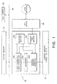
- Fig. 1 shows an ATM device operating as a communication control device according to a preferred embodiment of the present invention.
- the shown ATM device will be explained assuming that it is used as the ATM terminal or the ATM server shown in Fig. 7 and in the ABR mode ATM network.
- the shown ATM device includes a system bus 20 to which are connected a system memory 21 for storing transmission data and received data, a host (CPU) 22 for controlling the whole system, and a transmission/reception control section 25 for performing transmitting/receiving operations with the ATM network in a later-described fashion.
- a physical (PHY) device 26 having an ATM physical layer function.
- a control memory 27 for storing later-described table and various control data.
- the transmission/reception control section 25 can be structured by an LSI chip.
- the transmission/reception control section 25 includes a receiving section 250 connected to the PHY device 26, a transmitting section 251 connected to the PHY device 26, a host interface/DMA controller 252, a sequencer 253 and a control memory interface 254.
- the host interface/DMA controller 252 controls reading/writing operations of a register provided in the transmission/reception control section 25 and operations of reading/writing the transmission/received data relative to the system memory 21.
- the sequencer 253 controls the host interface/DMA controller 252 and the control memory interface 254 according to commands from the host 22.
- the receiving section 250 and the transmitting section 251 are connected to the host interface/DMA controller 252 and the control memory interface 254 for transmitting/receiving the transmission/received data therethrough.
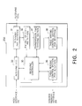
- the receiving section 250 shown in Fig. 1 includes a receiving controller 30 for sequentially controlling elements in the receiving section 250 according to commands fed via the host interface/DMA controller 252.
- the receiving section 250 further includes a receiving PHY interface 31, an RM cell detecting section 32, a receiving FIFO (first-in first-out memory) 33, a transmission time deriving section 34, a for-reception table reading control section 35 and a for-reception table writing control section 36.
- the control sections 35 and 36 are connected to the control memory interface 254 (see Fig. 1).
- the receiving PHY interface 31 separates a 53-byte ATM cell fed from the PHY device 26 (see Fig. 1) into a 5-byte header and a 48-byte payload and sends the header to the RM cell detecting section 32.
- the RM cell detecting section 32 detects from a format of the header whether the received cell is an RM cell or not. If positive, the payload of the received cell is outputted to the transmission time deriving section 34. On the other hand, if the received cell is not the RM cell, the payload of the received cell is stored in the receiving FIFO 33 in sequence. The stored payload is then transferred to the system memory 21 (see Fig. 1) through the DMA operation.
- the payload of the RM cell is given to the transmission time deriving section 34 where a time for transmitting an ATM cell next is calculated based on rate data and a current set value shown by the payload in the RM cell.
- the RM cell works as control data for deriving a transmission time, that is, a transmission timing.
- the derived time is written in a table of the control memory 27 via the for-reception table writing control section 36 and the control memory interface 254 under the control of the receiving controller 30.
- data or the like necessary for the receiving operation is read out from a table of the control memory 27 via the for-reception table reading control section 35 and fed to the receiving controller 30 according to necessity.
- the transmitting section 251 is also connected to the host interface 252 and the control memory interface 254 like the receiving section 250 and has a function to transmit an ATM cell to the PHY device 26.
- the transmitting section 251 includes a transmitting controller 40 connected to the host interface 252.
- the transmitting controller 40 controls elements in the transmitting section 251 in a later-described fashion.
- the transmitting section 251 further includes a transmitting FIFO 41 and a transmitting PHY interface 42 connected to the transmitting FIFO 41.
- a cell is formed by a cell payload including data transferred from the system memory 21 (see Fig. 1) through the DMA operation and a cell header including data from the control memory 27 (see Fig. 1), and stored temporarily in the transmitting FIFO 41 in sequence.
- the stored cell is transmitted in sequence to the PHY device 26 via the transmitting PHY interface 42 in the form of a 53-byte ATM cell.
- RM cells are also sent out via the transmitting PHY interface 42 like the other ATM cells.
- the transmitting FIFO 41 and the transmitting PHY interface 42 operate as ATM cell transmitting means.
- the transmitting controller 40 is connected to the control memory interface 254 via a for-transmission table reading control section 45 and a for-transmission table writing control section 46, respectively. Under the control of the transmitting controller 40, the control sections 45 and 46 perform data reading and data writing relative to a table of the control memory 27.
- the transmitting section 251 further includes a counter 50 and a CAM (content addressable memory), that is, an associative memory 51.
- the counter 50 and the CAM 51 are connected to the transmitting controller 40 for changing a transmission timing for a virtual channel VC depending on peak rates of the respective virtual channels VC.
- Fig. 4 shows a structure of the CAM 51 along with the counter 50 shown in Fig. 3.
- the CAM 51 includes a CAM cell array section 511 including a plurality of cell arrays, an address decoder 512, a collating register 513, a priority encoder 514, a retrieving/writing mode switching section 515 and a selector 516.
- the CAM 51 outputs an address of the stored data.
- a time value (T) representing a transmission timing for a virtual channel VC to be used next is written in a cell array of the CAM cell array section 511.
- this time value (T) matches with a value identified by the counter 50, an address where this time value (T) is stored can be determined as a virtual channel VC for a cell to be transmitted next.
- the transmitting controller 40 feeds to the retrieving/writing mode switching section 515 a mode switching signal representing whether to set the CAM cell array section 511 to a retrieving mode or a writing mode.
- the retrieving/writing mode switching section 515 sends a selection signal to the selector 516.
- the selector 516 selects a counter value of the counter 50, while, in case of the writing mode, the selector 516 selects an output from the transmitting controller 40, that is, a time value (Tp + Ts) representing a transmission timing for the next virtual channel VC.
- a writing address or a reading address is fed to the address decoder 512 of the CAM 51.
- a writing address or a reading address a number of a virtual channel VC corresponding to a cell array in the CAM 51 is given.
- a time value representing a transmission timing for the next virtual channel VC is written in a cell array designated by a writing address.
- a counter value of the counter 50 and time values in the cell arrays are compared, and an address of the matched cell array is outputted.
- the collating register 513 having storage positions corresponding to the respective cell arrays is provided. A logical level "1" is stored in a storage position corresponding to the matched cell array, while a logical level "0" is stored in a storage position corresponding to the disagreed cell array.
- the priority encoder 514 is provided so that cell transmission is started from a virtual channel VC having a higher priority in sequence.
- a table having a structure shown in Fig. 6 is stored. As seen from Fig. 6, a peak rate (Tp), a current CAM set value (Ts), the number N of sent ATM cells, a cell_sent flag representing whether an ATM cell in question is sent or not, a cell header and an RM cell payload are stored per virtual channel VC.
- Tp peak rate
- Ts current CAM set value
- N the number of sent ATM cells
- cell_sent flag representing whether an ATM cell in question is sent or not
- a cell header and an RM cell payload are stored per virtual channel VC.
- the transmitting section 251 is operated via the host interface 252 in the transmission/reception control section 25.
- the for-transmission table reading control section 45 is operated so as to access the table of the control memory 27 via the control memory interface 254.
- Ts, Tp, N and the cell_sent flag are read out from a region of the table assigned to the terminal in question and received at the for-transmission table reading control section 45.
- the for-transmission table reading control section 45 performs an operation of reading out data, such as Ts, Tp, N and the cell_sent flag, from the table in the control memory 27.
- Read-out Ts, Tp, N and cell_sent flag are sent to the transmitting controller 40.
- the transmitting controller 40 sets the selector 516 to the retrieving mode via the retrieving/writing mode switching section 515, and further sends a start signal to the counter 50 so that the counter 50 starts incrementing a counter value thereof (step S5).
- a virtual channel VC to be used at the transmission time T is determined through a later-described operation.
- the transmitting controller 40 determines whether the read-out number N of the ATM cells reaches a given number Nrm which is required for sending an RM cell (step S6).
- the for-reception reading control section 35 of the receiving section 250 (see Fig. 2), under the control of the receiving controller 30, reads out the peak rate Tp and the current CAM set value Ts from the table of the control memory 27 and feeds them to the transmission time deriving section 34.
- the transmission time deriving section 34 adds Tp and Ts to derive a sum thereof, and sets this sum as a current CAM set value Ts.
- the transmission time deriving section 34 further controls the for-reception table writing control section 36 to write the new value Ts in the region assigned to the current CAM set value Ts (step S7).
- the peak rate Tp is written in and read out from the table under the control of the receiving section 250.
- the current CAM set value Ts is written in the table under the control of the receiving section 250, while, as described later, is read out under the control of the transmitting section 251.
- the transmitting controller 40 sets the CAM 51 to the writing mode and sends a writing address corresponding to the virtual channel VC in question to the CAM 51.
- the transmitting controller 40 controls the for-transmission reading control section 45 (see Fig. 3) to read out the current CAM set value Ts stored in the table in the form of the foregoing sum as a next ATM transmission time T, and then outputs the read-out value Ts to the CAM 51.
- the inputted current CAM set value Ts is selected via the selector 516 and written in a CAM array corresponding to the virtual channel VC as the next transmission time T (step S8).
- step S9 the routine proceeds to step S9.
- the selector 516 is set in the retrieving mode by the retrieving/writing mode switching section 515 so as to select the counter value of the counter 50 being sequentially incremented.
- the values (next transmission time T) stored in the CAM array section 511 and the counter value are compared with each other (step S9).
- step S9 determines whether agreement between the counter value and the stored value is detected at step S9. If agreement between the counter value and the stored value is detected at step S9, a logical level "1" representing "agreement” is stored in the collating register 513 (see Fig. 4). On the other hand, in case of "disagreement” at step S9, a logical level "0" is stored in the collating register 513. Subsequently, step S10 determines using the priority encoder 514 whether the number of agreements, that is, the number of logical levels "1", stored in the collating register 513 exceeds 1. If the number of agreements is only one, an address of the CAM array where the agreement is detected, is determined as a virtual channel VC for transmission (step S11).
- the priority encoder 514 performs a priority control for a plurality of virtual channels VC so as to determine the virtual channel VC having a higher priority as a virtual channel VC for transmission (steps S12 and S11).
- the transmission controller 40 sets the cell_sent flag to 1 and the number N of sent ATM cells to (N +1) and writes them in the table of the control memory 27 via the for-transmission table writing control section 46 (step S13).
- the operations in steps S6-S13 are repeated until the number N of sent ATM cells becomes equal to Nrm at step S6.
- the determined virtual channel VC is sent to the transmitting controller 40 where a header and a payload are arranged based on a transmission timing of the determined virtual channel VC so as to form an ATM cell.
- the ATM cell is sent to the PHY device 26 (see Fig. 1) via the transmitting FIFO 41 and the transmitting PHY interface 42.
- the transmitting controller 40 transmits an RM cell to the PHY device 26 via the transmitting FIFO 41 and the transmitting PHY interface 42, while sets the number N of sent ATM cells in the table of the control memory 27 to 0 (step S14). Thereafter, as long as no RM cell is received at the receiving section 250 (see Fig. 2) from the ATM network, the transmitting section 251 repeats the operations in steps S1-S13.
- the RM cell detecting section 32 in the receiving section 250 constantly monitors reception of the RM cell. If the RM cell detecting section 32 detects reception of the RM cell from the ATM network via the PHY device 26, the receiving controller 30 determines whether a change in peak rate Tp due to jamming or the like is instructed in the RM cell (step S16). As long as there is no change in peak rate Tp, steps S15 and S16 are repeated in the receiving section 250.
- the receiving controller 30 detects that a change in peak rate Tp is instructed in the RM cell received via the receiving PHY interface 31, the receiving controller 30 updates the peak rate Tp stored in the table of the control memory 27 with the received peak rate Tp via the for-reception table writing control section 36 (step S17).
- the received peak rate Tp is sent from the RM cell detecting section 32 to the transmission time deriving section 34 where it is added to the current CAM set value Ts stored in the table to derive a sum thereof, and this sum is written in the table via the for-reception table writing control section 36.
- the foregoing current CAM set value Ts is fed to the receiving controller 30 from the control memory 27 via the for-reception table reading control section 35.
- the peak rate Tp and the current CAM set value Ts are set to 2 and 3, respectively, in the initialized state.
- 3 is written in the CAM 51 at step S4.
- the cell-sent flag is set to 1, 5 which is the sum of Tp and Ts is written in the CAM 51 at step S8.
- 7 which is the sum of 5 and 2 is written in the CAM 51 at the next execution of step S8.
- the transmission time for the virtual channels VC can be determined in sequence. Further, when the peak rate Tp is changed, the transmission time for the virtual channels VC can be changed adaptively depending on a change of the peak rate.
- the CAM arrays are used. On the other hand, a similar operation can be achieved using a plurality of comparators and a normal memory. Further, although explanation has been made to the case where the present invention is applied to the ABR mode, the present invention is also applicable to the CBR mode.
- the transmission/reception control section 25 shown in Fig. 1 may also be a terminal connected to the LAN.
- the transmission/reception control section 25, including further the control memory 27 if necessary, can be formed by an LSI chip, the structure can be made very compact in view of the hardware. Further, increment in number of the virtual channels VC can be dealt with only by increasing the memory capacity. Moreover, since no software switch is required, the cell transmission rate can be changed at high speed.
- the hardware can be further reduced, and even when agreements are detected simultaneously for a plurality of the virtual channels VC, it can be easily dealt with by performing the priority control.
Landscapes
- Engineering & Computer Science (AREA)
- Computer Networks & Wireless Communication (AREA)
- Signal Processing (AREA)
- Data Exchanges In Wide-Area Networks (AREA)
Applications Claiming Priority (2)
| Application Number | Priority Date | Filing Date | Title |
|---|---|---|---|
| JP13785295 | 1995-06-05 | ||
| EP96108878A EP0748088A3 (fr) | 1995-06-05 | 1996-06-03 | Appareil et méthode de contrÔle d'un système ATM, applicable dans un mode ABR |
Related Parent Applications (1)
| Application Number | Title | Priority Date | Filing Date |
|---|---|---|---|
| EP96108878A Division EP0748088A3 (fr) | 1995-06-05 | 1996-06-03 | Appareil et méthode de contrÔle d'un système ATM, applicable dans un mode ABR |
Publications (3)
| Publication Number | Publication Date |
|---|---|
| EP1686742A2 true EP1686742A2 (fr) | 2006-08-02 |
| EP1686742A3 EP1686742A3 (fr) | 2006-11-08 |
| EP1686742B1 EP1686742B1 (fr) | 2008-10-01 |
Family
ID=15208302
Family Applications (2)
| Application Number | Title | Priority Date | Filing Date |
|---|---|---|---|
| EP96108878A Ceased EP0748088A3 (fr) | 1995-06-05 | 1996-06-03 | Appareil et méthode de contrÔle d'un système ATM, applicable dans un mode ABR |
| EP06110422A Expired - Lifetime EP1686742B1 (fr) | 1995-06-05 | 1996-06-03 | Appareil et méthode de contrôle d'un système ATM, applicable dans un mode ABR |
Family Applications Before (1)
| Application Number | Title | Priority Date | Filing Date |
|---|---|---|---|
| EP96108878A Ceased EP0748088A3 (fr) | 1995-06-05 | 1996-06-03 | Appareil et méthode de contrÔle d'un système ATM, applicable dans un mode ABR |
Country Status (3)
| Country | Link |
|---|---|
| US (1) | US5875173A (fr) |
| EP (2) | EP0748088A3 (fr) |
| DE (1) | DE69637702D1 (fr) |
Families Citing this family (23)
| Publication number | Priority date | Publication date | Assignee | Title |
|---|---|---|---|---|
| JPH1023037A (ja) * | 1996-07-05 | 1998-01-23 | Nec Corp | トラヒックシェーピング方式 |
| JP2985844B2 (ja) * | 1997-09-08 | 1999-12-06 | 日本電気株式会社 | Atm受信装置 |
| US6115360A (en) * | 1997-11-21 | 2000-09-05 | Texas Instruments Incorporated | Fair scheduling of ATM cell transmissions during overscheduled conditions |
| US6791943B1 (en) * | 1998-02-27 | 2004-09-14 | Agilent Technologies, Inc. | Event-based technique for determining instantaneous cell bandwidth in a digital communications network |
| US6167028A (en) * | 1998-06-01 | 2000-12-26 | Motorola, Inc. | Methods and apparatus for facilitating transmission of cells having multiple priorities in a cell relay network |
| US6604136B1 (en) | 1998-06-27 | 2003-08-05 | Intel Corporation | Application programming interfaces and methods enabling a host to interface with a network processor |
| US6728249B2 (en) | 1998-06-27 | 2004-04-27 | Intel Corporation | System and method for performing cut-through forwarding in an ATM network supporting LAN emulation |
| US6425067B1 (en) | 1998-06-27 | 2002-07-23 | Intel Corporation | Systems and methods for implementing pointer management |
| US6657959B1 (en) * | 1998-06-27 | 2003-12-02 | Intel Corporation | Systems and methods for implementing ABR with guaranteed MCR |
| US6501731B1 (en) | 1998-06-27 | 2002-12-31 | Intel Corporation | CBR/VBR traffic scheduler |
| US6724767B1 (en) | 1998-06-27 | 2004-04-20 | Intel Corporation | Two-dimensional queuing/de-queuing methods and systems for implementing the same |
| US6311212B1 (en) | 1998-06-27 | 2001-10-30 | Intel Corporation | Systems and methods for on-chip storage of virtual connection descriptors |
| US6603768B1 (en) | 1998-06-27 | 2003-08-05 | Intel Corporation | Multi-protocol conversion assistance method and system for a network accelerator |
| US6735773B1 (en) | 1998-06-27 | 2004-05-11 | Intel Corporation | Method and apparatus for issuing commands to a network processor configured to provide a plurality of APIs |
| KR100294002B1 (ko) * | 1998-09-23 | 2001-08-07 | 윤종용 | 비동기전송모드 네트워크에서 실시간 에이비알 트래픽 관리 방법 |
| US7289442B1 (en) | 2002-07-03 | 2007-10-30 | Netlogic Microsystems, Inc | Method and apparatus for terminating selected traffic flows |
| US7346000B1 (en) * | 2002-07-03 | 2008-03-18 | Netlogic Microsystems, Inc. | Method and apparatus for throttling selected traffic flows |
| US7349332B1 (en) * | 2002-07-03 | 2008-03-25 | Netlogic Microsystems, Inc. | Apparatus for queuing different traffic types |
| US7342886B1 (en) * | 2002-07-03 | 2008-03-11 | Netlogic Microsystems, Inc. | Method and apparatus for managing individual traffic flows |
| US7616571B1 (en) | 2002-07-03 | 2009-11-10 | Netlogic Microsystems, Inc. | Method and apparatus for calculating packet departure times |
| WO2006075390A1 (fr) * | 2005-01-14 | 2006-07-20 | Fujitsu Limited | Procede de repetition, repeteur, systeme de communication et programme informatique |
| US7764676B1 (en) * | 2006-07-31 | 2010-07-27 | Qlogic, Corporation | Method and system for processing network information |
| US9057788B2 (en) * | 2012-02-03 | 2015-06-16 | Analogic Corporatiom | Photon counting-based virtual detector |
Citations (3)
| Publication number | Priority date | Publication date | Assignee | Title |
|---|---|---|---|---|
| US5313579A (en) * | 1992-06-04 | 1994-05-17 | Bell Communications Research, Inc. | B-ISDN sequencer chip device |
| US5313454A (en) * | 1992-04-01 | 1994-05-17 | Stratacom, Inc. | Congestion control for cell networks |
| EP0632622A1 (fr) * | 1993-06-24 | 1995-01-04 | France Telecom | Procédé pour espacer temporellement les émissions de cellules appartenant à des messages ainsi que des dispositifs pour la mise en oeuvre d'un tel procédé |
Family Cites Families (12)
| Publication number | Priority date | Publication date | Assignee | Title |
|---|---|---|---|---|
| US5119367A (en) * | 1988-10-28 | 1992-06-02 | Oki Electric Industry Co., Ltd. | Method and a node circuit for routing bursty data |
| US5319638A (en) * | 1991-09-12 | 1994-06-07 | Bell Communications Research, Inc. | Link-by-link congestion control for packet transmission systems |
| FR2694671A1 (fr) * | 1992-08-06 | 1994-02-11 | Trt Telecom Radio Electr | Dispositif de réarrangement de débits de circuits virtuels en transmission à multiplexage temporel asynchrone. |
| GB2288947B (en) * | 1994-04-20 | 1999-01-06 | Roke Manor Research | Improvements in or relating to ATM communication systems |
| US5515359A (en) * | 1994-08-26 | 1996-05-07 | Mitsubishi Electric Research Laboratories, Inc. | Credit enhanced proportional rate control system |
| US5649110A (en) * | 1994-11-07 | 1997-07-15 | Ben-Nun; Michael | Traffic shaping system with virtual circuit table time stamps for asynchronous transfer mode networks |
| US5675576A (en) * | 1995-06-05 | 1997-10-07 | Lucent Technologies Inc. | Concestion control system and method for packet switched networks providing max-min fairness |
| US5638371A (en) * | 1995-06-27 | 1997-06-10 | Nec Usa, Inc. | Multiservices medium access control protocol for wireless ATM system |
| US5633870A (en) * | 1995-07-07 | 1997-05-27 | Sun Microsystems, Inc. | Method and apparatus for controlling data flow through an ATM interface |
| US5684791A (en) * | 1995-11-07 | 1997-11-04 | Nec Usa, Inc. | Data link control protocols for wireless ATM access channels |
| US5699346A (en) * | 1995-11-17 | 1997-12-16 | Telecommunications Techniques Corporation | Measuring burst rate and burst size in ATM network virtual connections |
| US5737313A (en) * | 1996-03-15 | 1998-04-07 | Nec Usa, Inc. | Design of a closed loop feed back control for ABR service |
-
1996
- 1996-06-03 DE DE69637702T patent/DE69637702D1/de not_active Expired - Lifetime
- 1996-06-03 EP EP96108878A patent/EP0748088A3/fr not_active Ceased
- 1996-06-03 EP EP06110422A patent/EP1686742B1/fr not_active Expired - Lifetime
- 1996-06-05 US US08/655,219 patent/US5875173A/en not_active Expired - Lifetime
Patent Citations (3)
| Publication number | Priority date | Publication date | Assignee | Title |
|---|---|---|---|---|
| US5313454A (en) * | 1992-04-01 | 1994-05-17 | Stratacom, Inc. | Congestion control for cell networks |
| US5313579A (en) * | 1992-06-04 | 1994-05-17 | Bell Communications Research, Inc. | B-ISDN sequencer chip device |
| EP0632622A1 (fr) * | 1993-06-24 | 1995-01-04 | France Telecom | Procédé pour espacer temporellement les émissions de cellules appartenant à des messages ainsi que des dispositifs pour la mise en oeuvre d'un tel procédé |
Also Published As
| Publication number | Publication date |
|---|---|
| EP0748088A3 (fr) | 1999-12-15 |
| EP0748088A2 (fr) | 1996-12-11 |
| EP1686742A3 (fr) | 2006-11-08 |
| US5875173A (en) | 1999-02-23 |
| EP1686742B1 (fr) | 2008-10-01 |
| DE69637702D1 (de) | 2008-11-13 |
Similar Documents
| Publication | Publication Date | Title |
|---|---|---|
| EP1686742A2 (fr) | Appareil et méthode de contrôle d'un système ATM, applicable dans un mode ABR | |
| EP0858717B1 (fr) | Amelioration concernant un selecteur d'acheminement mta | |
| EP0858718B1 (fr) | Ameliorations concernant un commutateur mta | |
| US5987008A (en) | ATM switch | |
| US5719865A (en) | Traffic shaping method and apparatus for ATM switching unit | |
| EP0828403B1 (fr) | Améliorations dans ou liées à un commutateur ATM | |
| US6144640A (en) | ATM switch | |
| US6212196B1 (en) | Multiple access communication system and method for multiple access communication | |
| EP0858716B1 (fr) | Ameliorations apportees a un commutateur mta | |
| JP3134702B2 (ja) | 通信制御装置及びその制御方法 | |
| US5923645A (en) | Cell rate control device and method | |
| US5910953A (en) | ATM interface apparatus for time-division multiplex highways | |
| EP0604538A1 (fr) | Procede et appareil destines a un reseau a mode de transfert asynchrone (mta) | |
| JP2899609B2 (ja) | セル送出装置 | |
| US20020031129A1 (en) | Method of managing voice buffers in dynamic bandwidth circuit emulation services | |
| JP3094995B2 (ja) | 通信制御装置及び通信制御方法 | |
| GB2366933A (en) | Method of managing circular buffers in dynamic bandwidth circuit emulation services | |
| KR100381378B1 (ko) | 에이티엠 셀 스케쥴러 및 스케쥴링 방법 | |
| KR100282405B1 (ko) | 에이티엠 교환기에서 셀 큐잉 장치 및 방법 |
Legal Events
| Date | Code | Title | Description |
|---|---|---|---|
| PUAI | Public reference made under article 153(3) epc to a published international application that has entered the european phase |
Free format text: ORIGINAL CODE: 0009012 |
|
| AC | Divisional application: reference to earlier application |
Ref document number: 0748088 Country of ref document: EP Kind code of ref document: P |
|
| AK | Designated contracting states |
Kind code of ref document: A2 Designated state(s): AT BE BG CH CY CZ DE DK EE ES FI FR GB GR HU IE IS IT LI LT LU LV MC NL PL PT RO SE SI SK TR |
|
| AX | Request for extension of the european patent |
Extension state: AL BA HR MK YU |
|
| PUAL | Search report despatched |
Free format text: ORIGINAL CODE: 0009013 |
|
| AK | Designated contracting states |
Kind code of ref document: A3 Designated state(s): AT BE BG CH CY CZ DE DK EE ES FI FR GB GR HU IE IS IT LI LT LU LV MC NL PL PT RO SE SI SK TR |
|
| AX | Request for extension of the european patent |
Extension state: AL BA HR MK YU |
|
| 17P | Request for examination filed |
Effective date: 20070316 |
|
| AKX | Designation fees paid |
Designated state(s): DE FR GB NL |
|
| GRAP | Despatch of communication of intention to grant a patent |
Free format text: ORIGINAL CODE: EPIDOSNIGR1 |
|
| RAP1 | Party data changed (applicant data changed or rights of an application transferred) |
Owner name: NEC ELECTRONICS CORPORATION |
|
| GRAS | Grant fee paid |
Free format text: ORIGINAL CODE: EPIDOSNIGR3 |
|
| GRAA | (expected) grant |
Free format text: ORIGINAL CODE: 0009210 |
|
| AC | Divisional application: reference to earlier application |
Ref document number: 0748088 Country of ref document: EP Kind code of ref document: P |
|
| AK | Designated contracting states |
Kind code of ref document: B1 Designated state(s): DE FR GB NL |
|
| REG | Reference to a national code |
Ref country code: GB Ref legal event code: FG4D |
|
| REF | Corresponds to: |
Ref document number: 69637702 Country of ref document: DE Date of ref document: 20081113 Kind code of ref document: P |
|
| PLBE | No opposition filed within time limit |
Free format text: ORIGINAL CODE: 0009261 |
|
| STAA | Information on the status of an ep patent application or granted ep patent |
Free format text: STATUS: NO OPPOSITION FILED WITHIN TIME LIMIT |
|
| 26N | No opposition filed |
Effective date: 20090702 |
|
| REG | Reference to a national code |
Ref country code: NL Ref legal event code: TD Effective date: 20100715 |
|
| REG | Reference to a national code |
Ref country code: FR Ref legal event code: CD |
|
| REG | Reference to a national code |
Ref country code: DE Ref legal event code: R082 Ref document number: 69637702 Country of ref document: DE Representative=s name: BETTEN & RESCH, DE |
|
| REG | Reference to a national code |
Ref country code: DE Ref legal event code: R082 Ref document number: 69637702 Country of ref document: DE Representative=s name: PATENTANWAELTE BETTEN & RESCH, DE Effective date: 20120828 Ref country code: DE Ref legal event code: R081 Ref document number: 69637702 Country of ref document: DE Owner name: RENESAS ELECTRONICS CORPORATION, JP Free format text: FORMER OWNER: NEC ELECTRONICS CORP., KAWASAKI, JP Effective date: 20120828 Ref country code: DE Ref legal event code: R081 Ref document number: 69637702 Country of ref document: DE Owner name: RENESAS ELECTRONICS CORPORATION, KAWASAKI-SHI, JP Free format text: FORMER OWNER: NEC ELECTRONICS CORP., KAWASAKI, KANAGAWA, JP Effective date: 20120828 Ref country code: DE Ref legal event code: R082 Ref document number: 69637702 Country of ref document: DE Representative=s name: BETTEN & RESCH PATENT- UND RECHTSANWAELTE PART, DE Effective date: 20120828 |
|
| PGFP | Annual fee paid to national office [announced via postgrant information from national office to epo] |
Ref country code: GB Payment date: 20130529 Year of fee payment: 18 |
|
| PGFP | Annual fee paid to national office [announced via postgrant information from national office to epo] |
Ref country code: FR Payment date: 20130624 Year of fee payment: 18 |
|
| PGFP | Annual fee paid to national office [announced via postgrant information from national office to epo] |
Ref country code: DE Payment date: 20140528 Year of fee payment: 19 Ref country code: NL Payment date: 20140510 Year of fee payment: 19 |
|
| GBPC | Gb: european patent ceased through non-payment of renewal fee |
Effective date: 20140603 |
|
| REG | Reference to a national code |
Ref country code: FR Ref legal event code: ST Effective date: 20150227 |
|
| PG25 | Lapsed in a contracting state [announced via postgrant information from national office to epo] |
Ref country code: FR Free format text: LAPSE BECAUSE OF NON-PAYMENT OF DUE FEES Effective date: 20140630 Ref country code: GB Free format text: LAPSE BECAUSE OF NON-PAYMENT OF DUE FEES Effective date: 20140603 |
|
| REG | Reference to a national code |
Ref country code: DE Ref legal event code: R119 Ref document number: 69637702 Country of ref document: DE |
|
| REG | Reference to a national code |
Ref country code: NL Ref legal event code: MM Effective date: 20150701 |
|
| PG25 | Lapsed in a contracting state [announced via postgrant information from national office to epo] |
Ref country code: DE Free format text: LAPSE BECAUSE OF NON-PAYMENT OF DUE FEES Effective date: 20160101 Ref country code: NL Free format text: LAPSE BECAUSE OF NON-PAYMENT OF DUE FEES Effective date: 20150701 |