EP1686479A2 - Übertragung von Informationen von einem hochfunktionalem Taskkopf zu einem Logikanalysator - Google Patents
Übertragung von Informationen von einem hochfunktionalem Taskkopf zu einem Logikanalysator Download PDFInfo
- Publication number
- EP1686479A2 EP1686479A2 EP05254989A EP05254989A EP1686479A2 EP 1686479 A2 EP1686479 A2 EP 1686479A2 EP 05254989 A EP05254989 A EP 05254989A EP 05254989 A EP05254989 A EP 05254989A EP 1686479 A2 EP1686479 A2 EP 1686479A2
- Authority
- EP
- European Patent Office
- Prior art keywords
- point
- link
- information
- packet
- additional
- Prior art date
- Legal status (The legal status is an assumption and is not a legal conclusion. Google has not performed a legal analysis and makes no representation as to the accuracy of the status listed.)
- Withdrawn
Links
Images


Classifications
-
- H—ELECTRICITY
- H04—ELECTRIC COMMUNICATION TECHNIQUE
- H04L—TRANSMISSION OF DIGITAL INFORMATION, e.g. TELEGRAPHIC COMMUNICATION
- H04L12/00—Data switching networks
- H04L12/02—Details
-
- G—PHYSICS
- G06—COMPUTING OR CALCULATING; COUNTING
- G06F—ELECTRIC DIGITAL DATA PROCESSING
- G06F11/00—Error detection; Error correction; Monitoring
- G06F11/22—Detection or location of defective computer hardware by testing during standby operation or during idle time, e.g. start-up testing
- G06F11/25—Testing of logic operation, e.g. by logic analysers
-
- H—ELECTRICITY
- H04—ELECTRIC COMMUNICATION TECHNIQUE
- H04L—TRANSMISSION OF DIGITAL INFORMATION, e.g. TELEGRAPHIC COMMUNICATION
- H04L47/00—Traffic control in data switching networks
- H04L47/10—Flow control; Congestion control
-
- H—ELECTRICITY
- H04—ELECTRIC COMMUNICATION TECHNIQUE
- H04L—TRANSMISSION OF DIGITAL INFORMATION, e.g. TELEGRAPHIC COMMUNICATION
- H04L47/00—Traffic control in data switching networks
- H04L47/10—Flow control; Congestion control
- H04L47/43—Assembling or disassembling of packets, e.g. segmentation and reassembly [SAR]
Definitions
- the field of invention relates generally to debug/validation/testing tools for link-based computing systems; and, more specifically, to an information transportation scheme for carrying data and control information from a high functionality probe to a logic analyzer for storage.
- FIG. 1a shows a depiction of a bus 120.
- a bus 120 is a "shared medium", multi-drop communication structure that is used to transport communications between electronic components 101a - 10Na and 110a.
- Shared medium means that the components 101a - 10Na and 110a that communicate with one another physically share and are connected to the same parallel signals electronic wiring 120. That is, wiring 120 is a shared resource that is used by any of components 101a - 10Na and 110a to communicate with any other of components 101a - 10Na and 110a.
- component 101 a wished to communicate to component 10Na, component 101 a would send information along wiring 120 to component 10Na; if component 103a wished to communicate to component 110a, component 103a would send information along the same wiring 120 to component 110a, etc.
- bus 120 corresponds to a PCI bus where components 101a - 10Na correspond to "I/O" components (e.g., LAN networking adapter cards, MODEMS, hard disk storage devices, etc.) and component 110a corresponds to an I/O Control Hub (ICH).
- I/O I/O Control Hub
- bus 120 corresponds to a "front side" bus where components 101a - 10Na correspond to microprocessors and component 110a corresponds to a memory controller.
- busses are less and less practical as computing system speeds grow. Basically, as the capacitive loading of any wiring increases, the maximum speed at which that wiring can transport information decreases. That is, there is an inverse relationship between a wiring's capacitive loading and that same wiring's speed. Each component that is added to a wire causes that wire's capacitive loading to grow. Likewise, at increased frequencies, transmission lines forming the bus experience increased signal integrity degradation as result of topology complexities (discontinuities at branches and any other points where the impedance of the transmission line changes), high frequency losses in dielectrics, inter-signal coupling, and other high frequency effects. Thus, because busses typically couple multiple components, bus wiring 120 is typically regarded as being heavily loaded with capacitance as well as having other transfer rate limiting signal degradation problems.
- FIG. 1b shows a comparative example of a point to point links interconnected system vis-à-vis the multi-drop configuration in Figure 1a.
- computing system components 101a - 10Na and 110a are interconnected through a network 140 of high speed bi-directional point-to-point links 130 1 through 130 N .
- Each point-to-point link comprises a first unidirectional point-to-point link that transmits information in a first direction and a second unidirectional point-to-point link that transmits information is a second direction that is opposite that of the first direction. Because a unidirectional point-to-point link typically has a single endpoint, and a simple un-branched topology, its capacitive loading and other high frequency degradation effects are substantially less than that of a shared media bus.
- Each unidirectional point-to-point link can be constructed with copper or fiber optic cabling and appropriate drivers and receivers (e.g., single or differential line drivers and receivers for copper based cables; and LASER or LED Electrical/Optical transmitters and Optical/Electrical receivers for fiber optic cables, etc.).
- the network 140 observed in Figure 1b is simplistic in that each component is connected by a point-to-point link to every other component. In more complicated schemes, the network 140 has additional elements such as link repeaters and/or routing/switching nodes. Here, every component need not be coupled by a point-to-point link to every other component Instead, hops across a plurality of links may take place through routing/switching nodes in order to transport information from a source component to a destination component.
- the routing/switching function may be stand alone within the network or may be integrated into a substantive component of the computing system (e.g., processor, memory controller, I/O unit, etc.).
- logic analyzers have been used to "snoop" a bus within the computing system to de-bug the informational flows that transpire within the computing system. Because of the emergence of link based computing systems, however, new logic analyzer designs are appropriate.
- Figure 1a shows components interconnected through a multi-drop bus
- Figure 1b shows components interconnected through a network of point-to-point links
- Figure 2 shows a logic analyzer probing architecture for forwarding information extracted from a probed point-to-point link within a link based computing system from a link traffic capture and protocol decoding front end via a specialized serial link to a back end, typically outside the observed system, for trace storage;
- Figure 3 shows a parallel packet information content format that the architecture of Figure 2 may be designed to forward downstream from the probed point-to-point link to the storage module(s);
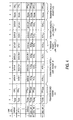
- Figure 4 shows an example of transfer packets sent from a link side interface to a host side interface
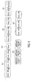
- Figure 5 shows an example of the signaling protocol/format that the architecture of Figure 2 may be designed to implement as it passes parallel packets downstream.
- Figure 2 shows a logic analyzer probing architecture for forwarding information extracted from a probed point-to-point link within a link based computing system.
- link 202 corresponds to any uni-directional point-to-point link within a link based computing system having a corresponding driver 201 and receiver 203.
- the probing architecture includes: 1) a link-side logic analyzer interface 221; 2) a host side logic analyzer interface 222; and, 3) a plurality of point-to-point links 214 between the interfaces 221, 222.
- the point-to-point links 214 allow the portion of the logic analyzer (e.g., computing system 233) that is responsible for actually displaying to a user its measurement results to be physically separated from the link side logic analyzer interface 221.
- the logic analyzer e.g., computing system 233
- link based computing systems have the potential to be spread out over distances that exceed those of traditional bus based computing systems
- a logic analyzer's "host” e.g., its mainframe, display, user interface, and/or control center
- the plurality of links 214 allows information that is collected from the probed link 202 to be passed "downstream" (i.e., away from the link and deeper within the logic analyzer) at a high rate of speed in the form of "transfer" packets.
- host e.g., its mainframe, display, user interface, and/or control center
- a perspective of the architecture of Figure 2 is that a highly intelligent device, referred to as a capture controller 204, sits "out at the probed link" 202. That is, the capture controller 204 is located on the logic analyzer interface 221 that is physically coupled to the link 202 being probed.
- the capture controller 204 (or circuitry between the capture controller and the link 202) includes a power splitter and re-driver 205 circuit that: 1) splits the signal driven by driver 201 into a pair of signals; and, 2) of these pair of signals, re-drives a first signal across the remainder of link 202 to receiver 203 and directs a second signal into the capture controller 204 so that the link's informational content can be probed.
- a power splitter and re-driver 205 circuit that: 1) splits the signal driven by driver 201 into a pair of signals; and, 2) of these pair of signals, re-drives a first signal across the remainder of link 202 to receiver 203 and directs a second signal into the
- the link specific, "protocol aware” capture controller 204 is capable of performing the following functions: 1) recognizing packet boundaries and individual packets on link 202; 2) understanding the content of the headers of the packets on link 202; 3) identifying the existence of particular "looked for" packets on link 202 as control for packet capture filtering and for detection of trigger events (as a consequence of capture controller 204 being programmatically told to look for a specific packet types, by matching packet headers or having specific data payloads on link 202); 4) providing capture for trace of information found within the payload and/or header of a packet that has appeared on link 202; 5) understanding the state of the link (e.g., "initialization", “down”, “active”, etc.); 6) providing one or more "trigger” signals 211 to downstream circuitry that signifies a looked for event (such as the appearance on the link of a particular looked for packet or sequence of packets) has occurred (note: along with the trigger signal itself the capture controller 204 would also provide
- the "raw data" output 235 corresponds to the output where the header and/or payload information of a packet that has appeared on link 202 is presented; and, the "decoded information” output 236 corresponds to the output where the identity of a particular type of packet that has appeared on the link (e.g., a link initialization packet, a request packet used within the link-based computing system, data packet used within the link-based computing system, a control packet used within the link-based computing system, etc.) is presented or a particular type of link event or state (e.g., active, initialization, re-initialization, etc.) is presented.
- Trigger output 211 is used to provide the aforementioned trigger signal.
- Filter output 250 is used to signal for each received packet as to whether a valid packet or timestamp vs. a filtered gap appears at that point in time, Only valid packets and timestamps are accumulated in queue 215 to be passed across the link 214 as transfer packets for storage under control of the transmit controller 209.
- Control input 212 is used to program the capture controller 204 to look for certain packets/events on link 202 and provide decodes of link 202 information at outputs 235/236/211/250 in response thereto.
- Communication inputs 251, 252 from the host 233 to both the link side 221 and host side 222interfaces are to allow setting these and other parameters in each, respectively.
- the entire link side logic analyzer interface 221, including the capture controller 204 would be implemented with a high density logic semiconductor device (e.g., such as an ultra or very large scale integrated circuit made with CMOS circuitry (e.g., an ASIC)). It will be appreciated that specific design details concerning the capture controller 204 need not be presently discussed not only because the present application is directed to the manner in which information provided by the capture controller 204 is forwarded downstream within the logic analyzer; but also, because those of ordinarily skill would be able to design a capture controller that performs the above described functions without undue experimentation.
- CMOS circuitry e.g., an ASIC
- the time stamp structures 207, 208 are used to provide precise measurement and storage into the trace of the amount of time that has elapsed between substantive capture controller outputs.
- the time stamp structures 207, 208 would be used to forward the fact that 5 milliseconds had elapsed on the link between the arrival of the first packet and the arrival of the second packet by capture controller 204.
- the timestamp of an elapse time of 5 milliseconds would be forward downstream from the link-side interface 221 to the host-side interface 222 along with the indication of the content and decodes of the second packet.
- the host-side interface 222 would first receive an indication of the arrival of the first packet (i.e. the content and decode of that packet). Then, sometime later (approximately 5 milliseconds later), the host-side interface 222 would receive first the timestamp value of 5 milliseconds followed immediately by the second packet content and decode information. The logic analyzer could then interpret this information flow to mean that the second packet arrived 5 milliseconds after the first packet as measured on link 202.
- the timestamp structure itself works as follows.
- the local device time counter value (timestamp) at which the most recent looked for (i.e. non-filtered) characteristic packet appeared on link 202 is stored into register 208.
- timestamp timestamp
- the capture controller 204 In response to the appearance of the second packet at device measured absolute time 1.025 seconds (i.e., 5 milliseconds after the appearance of the first packet), the capture controller 204 would select the timestamp input of multiplexer 206 so that the elapsed time (prior timestamp value minus current timestamp value) could be forward downstream to the host-side interface 222. Subsequently, the new absolute time of 1.025 seconds would be forwarded to register 208 to update register 208 with the absolute time of the appearance of the most recent looked for characteristic on link 202.
- the transmit controller 209 In response to the filter signal indicating "enable capture", the transmit controller 209 would store the information on bus 242 in the queue 215. At the same time, the capture controller would cause the timestamp counter 207 value with absolute time of 1.025 seconds to be entered into register 208.
- the capture controller 204 Upon the appearance of the second packet on link 202, the capture controller 204 would during the period corresponding to the last filtered packet, select the time stamp delay input (difference between current and previously entered timestamp values) to be output by multiplexer 206, and then in the period corresponding the second packet would select input 235 to multiplexer 206. For each of these the capture controller would again issue a filter signal asserted to "enable capture" on line 250 In response to the assertion of the filter signal, in an embodiment, the transmit controller 209 would store the passed elapsed delay and then the packet into the queue 215 for transmission to the host side interface as soon as enough data is available in the queue.
- the host side interface 222 would receive both an indication that 5 milliseconds has elapsed on link 202 and the content of the second packet.
- the logic analyzer host could properly put together the fact that packets having payload of "ABC” + "012...7” appeared on link 202 spaced apart by a time period of 5 milliseconds.
- An absolute time of 1.025 seconds would also be forwarded into register 208 to prepare for the third arrival of the looked for packet. The process described above for the second packet would then repeat for each appearance of a looked for packet on link 202.
- the capture controller 204 could be configured to simultaneously look for multiple types of packets or events on link 202.
- the capture could be configured to look for both packets having payload "000... 0" and packets having payload "000...1". If so, the operation could be identical as described above with the exception of the information provided at output 235 and combined with outputs 236 in bus 242 of the capture controller. That is, if the first packet had payload "000...0" and if the second packet had payload "000...
- output 236 would indicate a detected packet of payload "000...0” for the first packet (as described above) but would instead indicate a packet of payload "000...1” for the second packet, while raw data output 235 would contain the actual packet content for each.
- the logic analyzer host could properly understand that a packet having payload "000...1” appeared on link 202 with a delay equal to that passes as the timestamp delay after a packet having payload "000...0” appeared on link 202.
- each link amongst links 214 is viewed as a lane that is used to transport different piece(s) of a transfer packet that is transported in parallel across the parallel links 214 up to host side interface 222.
- widthwise LAI to host packets being transported from interface 221 to interface 222 could conceivably carry the full, identical content to those packets that are captured from link 202 (e.g., an entire packet captured from link 202 is presented at capture controller output 235 and routed widthwise across subset of links 214 up to interface 222), due to providing transport of decoded information and/or other auxiliary information, in all cases the widthwise transfer packets that are routed across links 214 up to interface 222 are something other than a simple exact copy of the packet to which they reference that appeared on link 202.
- these transfer packets carry not only the target link packet content, but also selected decodes (triggers) from the packets and timestamps, as well as link 214 control and error detection information.
- a target system link 202 packet may be composed of a number of primitive transfer packets on the system link 202 and therefore have a larger total content than can be carried in a single link 214 transfer packet transmission from the link interface 221 to host side 222 logic. In such cases the transfer shall require packing sequential system link 202 packets into multiples of the link side 221 to host side 222 transfer packets appearing on link 214 (e.g., as seen in region 402 of Figure 4 ).
- Figure 3 shows an embodiment of a widthwise transfer packet that may be presented across links 214.
- the width of the width wise transfer packet is N+Y units of encoded data (e.g., N+Y encoded bytes of data) where the payload is N units of encoded system link raw data or timestamp delay (selected through multiplexer 206) and the decoded information is Y units of encoded data originating from the capture controller 204 as decoded information 236.
- the payload 301 of the widthwise transfer packet consume lanes 1 through N and the decoded information 302 of the widthwise transfer packet consumes lanes N+1 through N+Y.
- Links/lanes 214 of Figure 2 correspond to links/lanes 314 of Figure 3 .
- a unit of encoded data is the result of encoding some fixed amount of data. For example, in the case of 8B/10B encoding, a unit of encoded data is the 10 bits that result from the encoding of a byte of data.
- the payload 301 of the widthwise transfer packet transports the information (system link packet content 235 or elapsed timestamp value) provided by multiplexer 206 in parallel with the decoded system link information 236. That is, the payload of any particular widthwise transfer packet 301 transports either timestamp information or payload information from a packet captured on link 202, and always includes decoded information 235 from the capture controller 204.
- the multiplexer 206 is divided into N sections, each of the N sections corresponding to a different one of N lane processing channels 210 1 through 210 N , and the corresponding payload lanes of links 214 to the host.
- the multiplexer 206 output 242 is drawn initially (before merging with decoded information 235) as an N wide channel where each of the N sections corresponds to a different subset (unit) of data from multiplexer 206 to be encoded.
- the decoded information 236 is merged with the output of multiplexer 206 into bus 242 prior to reaching the lane processing channels 210 n+1 through 210 N+Y .
- each unit of the Y section corresponds to a different subset (unit) of the decoded information 236.
- each of the N and Y sections corresponds to a different byte (8 bits) of information provided at the output of multiplexer 206 and the decoded information 236, respectively.
- the remaining lane processing channels 210 81 through 210 96 for the remaining 16 lanes of link 214 receive receives inputs for decoded information 236 in the capture controller 204.
- a transmit controller 209 is responsible for overseeing the flow of information that passes from the link-side logic analyzer interface 221 to the host-side logic analyzer interface 222.
- the transmit controller 209 recognizes when link 202 traffic, formatted as raw packets or timestamp delays in parallel with corresponding packet decode information, has accumulated in queue 215 to be encoded and transmitted downstream over link 214.
- FIG 2 shows in detail an embodiment of a lane processing channel 210 1 that is used for processing the first unit of data from amongst the N + Y units of data provided by the capture controller 204 via bus 242.
- the transmit controller stores that information into queue 215.
- the role of CRC generator 342 and multiplexer 216 will be described in more detail ahead with respect to Figure 5. Ignoring these items for a moment, units of information to be stored for host 233 are accumulated as they are queued in queue 215 and are eventually passed from queue 215 to encoder 217 for encoding.
- Encoding schemes can be designed to include features that significantly reduce the likelihood of data corruption on a point-to-point link arising from unbalanced data patterns (e.g., "all 1s” or "all Os").
- the most common type of encoding presently is 8b/10b although other types exist (e.g., 4b/5b, 64b/66b).
- An encoder is circuitry that is designed to perform an encoding function.
- each unit of data is encoded it is passed through a parallel to serial converter 218 and driven by a driver 219 (perhaps through an electrical or fiber optic cable connector 220) over a circuit board or coaxial electrical or fiber optic cable of which links 214 are comprised.
- the driven signal between interfaces 221, 222 may be differential or single ended.
- the output bus 242 from the capture controller is divided into N + Y sections, it is assumed that each of processing channels 210 1 through 210 N+Y will send a corresponding encoded unit of data up to interface 222.
- the host-side interface 222 will as necessary be able to properly align, through a suitable alignment protocol and mechanisms, the different pieces of a widthwise transfer packet's payload if they arrive at interface 222 at different times across the various lanes.
- a suitable alignment protocol is discussed in more detail ahead with respect to Figure 5. Note that in the case of fiber optic cabling, the different units of encoded data produced by the transmit processing chains may be wavelength division multiplexed onto a common fiber optic link (i.e., links 214 reduces to small number, or even a single physical link).
- Figure 4 shows an example of the flow of transfer packets across link 214.
- Link side transfer packets for link 214 are constructed simply through selection of an appropriate data structure (CRC, or packet data/decodings) through multiplexer 216 and then encoding by encoder 317, its serialization through serializer 219, and its being driven by driver 219 (perhaps through a connector such as connector 220) over its corresponding lane.
- CRC data structure
- serializer 219 serializer
- driver 219 perhaps through a connector such as connector 220
- All transfer packet payload signal values including either raw packet data or timestamp delay substitution for target and parallel decode information as well as CRC are selected through multiplexer 216 by the transmit controller 209 using signals 239.
- Protocol control signals Kcom and any others necessary for link training and host side storage synchronization, startup, and stopping are selected by the transmit controller through control line 240 and the encoder 217 (i.e., the encoder 217 generates protocol control signals) simultaneously in all of the lane processing channels.
- the transmit controller 209 keeps track of packets loaded into the queue 215 and when enough are available to allow encoding selects sets of values for encoding and transmission to the host. If not enough queue data is available, the transmit controller instead transmits one or more Kcom + CRC pairs which corresponds to a transfer packet (e.g., as seen in region 401 of Figure 4) until there is again enough data in the queue to encode and transmit across the full width of the N+Y lanes.
- the transmit controller transmits the payload and decoded information across the full width of the N+Y lanes (e.g., as seen in regions 402, 403, 404 for first through third 402, fourth 403 and fifth 404 transfer packets, respectively, which correspond to, respectively, zero 402, first 403 and second 404 link packets observed on link 202).
- the transmit controller starts transmitting only Kcom + CRC pairs (e.g., as seen in region 405 of Figure 4) indicating to the host interface that there is no further data to be stored (actually appearing identical to the transmission when there is no data being passed from the capture controller). Since the Kcom and CRC pairs (regions 401 and 405) are only link 214 control and error detection overhead added, these are processed to insure synchronization and transfer integrity are maintained, but are not stored in the host side interface logic analyzer.
- the host computer system 233 can at its leisure shut down capture in the host side interface 222 without having to precisely synchronize the shutdown of host side receive processing chains, allowing partitioning of the host side interface into multiple parallel devices such as commercial FPGAs.
- Host interface partitions only need to signal each other if a persistent error is detected by any of the partitions, such as due to loss of symbol framing
- Corrective action for such detected errors would require transmission via a single, or small number of signals 260 to allow the collective elements of a portioned host side interface 222 to request the single link side interface 221 to perform link 214 re-initialization and resumption of transfers.
- Auxiliary information (decode of link traffic defining content for each link 214 packet and carrying other information, such as produced triggers) is carried in fixed format in each packet (i.e. not accumulated over multiple transfer packets) even if it takes multiple transfer packets to carry a "long" target system packet to the host.
- a Kcom character in an embodiment, is a COMMA, an 8b/10b K control character selected by transmit controller 209 using control signals 240, 340 for creation by the encoder 217, 317.
- the Kcom character is a value provided by an encoder that is known (according to the encoding algorithm) to not correspond to any un-encoded data character. That is, encoding consists of taking un-encoded data and encoding it into a larger number of encoded data bits. Each possible pattern of un-encoded data is translated into a corresponding pattern of encoded data; where the encoded data patterns are constructed from a group of data patterns that is smaller than the full set of possible data patterns that could be constructed in light of the bit width of the encoded data patterns. Typically, balanced patterns (equal numbers of 1's and 0's in each allowed encoded value) are within the aforementioned group while unbalanced patterns are not within the aforementioned group.
- Kcom characters also come from the aforementioned group, but have different encodings than any of the data values and therefore are immediately identifiable as not corresponding to any data encodings.
- the Kcom character may therefore be used, as is the case in Figure 5 , to signify control symbols rather than data are being sent.
- the transmit controller 209 activates lines 240 for each of the widthwise packet lanes and lines. This activation causes the encoder of each lane to transmit a Kcom character over its corresponding lane.
- the CRC R data structure is a Cyclic Redundancy Check (CRC) RESET value.
- Cyclic Redundancy Checks are data checking schemes.
- a CRC scheme uses a specific mathematical function to calculate specific output values in response to specific input values.
- the algorithm recalculates a new output value using the algorithm's previous output value and the new piece of data as an input value.
- the calculated CRC for that sequence is sent along after it to a receiving end (in the case the host-side interface 222).
- the receiving end can re-calculate a CRC value that matches the CRC value from the received data stream, the data is deemed “not corrupted” by the transmission process; while, if the receiving end re-calculate a different value that the sent CRC value from the received data stream, it is deemed “corrupted” by the transmission process.
- a CRC RESET value (CRC R ) is the value at which the CRC value is set at the start of the CRC calculation process (i.e., the CRC output value to be used when the first piece of the data stream is submitted for CRC calculation).
- the CRC generators 242 are reset for all lanes, by the transmit controller 209 when it activates line 238, forcing the CRC generators 242 to be loaded with the CRC RESET value CRC R..
- the CRC is reset each time the value of the CRC is selected for encoding, so that a new CRC value can be accumulated for following data bytes from the queue 215. Likewise, when a value is pulled from the queue 215 for encoding, at that point in time it is also appropriate for the CRC to calculate a new output value, as selected by the transmit controller 209 activating line 261.
- the new CRC value is calculated from the prior CRC output value and the current value out of the queue 215.
- the CRC R value is selected for including in the stream of bytes to be encoded by the transmit controller 209 activating line 239 cause channel A of multiplexer 216 to be selected. As a consequence, a CRC R character will be encoded and transmitted over each lane of the link 214.
- the transmit controller 209 will effectively transmit alternating Kcom and CRC R characters as observed in Figure 5 over time period 501.
- Kcom character is sent when no data is available in queue 215 for transmission.
- the CRC generator 242 and multiplexer 216 are not needed during idle periods of transfer, but since these same mechanisms are required to support detection of corrupted non-idle data passed on the link, error detection would also be lost.
- the capture controller 204 is apt to send a trigger signal that a looked for item or event, signifying that tracing should cease, has appeared on link 202 with trigger decodes and link traffic passed via outputs 235, 236.
- the transmit controller 209 changes to a mode of sending the alternating Kcom and CRC on link 214.
- the transmit controller In order signal to host interface device(s) 222 that tracing should start (i.e. to start synchronize storage of data at an internally programmed starting point in storage buffers, the transmit controller creates and send the Kstart widthwise transfer packet 502. This is typically done upon request of the host computer 233 by accessing and setting register bits (or by signaling using dedicated discrete lines 250, 251) to the transmit controller 209. Upon being requested, the transmit controller 209 simply activates lines 240 for each of lane processing channels 210 1 through 210 N+Y causing the encoder to produce the Kstart character 502 onto all lanes of link 214. As a consequence of these maneuvers, a START widthwise packet 502 will be forwarded up to the host-side interface 222. The host-side interface will be able to recognize the presence of the START packet 502 by receiving the Kstart character on every lane of link 214.
- a START widthwise packet is followed by repeated "Kcom, CRC R " pairs 503 until there is trace data to transfer
- the "Kcom, CRC R " pairs 503 allows the substantive data captured by the capture controller 204 (e.g., decoded data provided at output 236 and raw data from output 235 or timestamp delays) to be loaded into the queues 215.
- the transmitter selects a data value from the queue in all lane processing channels 210 1 through 210 N+Y through multiplexer 216 of each of these channels, so that it is encoded, serialized and driven over its corresponding link.
- transmit controller 209 activates select line 239 of each of these channels to select channel B.
- the presence of the timestamp delay value vs. captured raw system link packet 235 in the payload section of each packet 314 on link 214 is identified specifically by bits or encodings in fields of the decoded information provided by capture controller 204 and passed unmodified in the header 302 along with the payload.
- the transmit controller has no knowledge of or need to know whether the payload of a link 214 packet is system link raw data or timestamp delay value, since it handles all values passed into the queue 215 identically. Therefore the first values passed through the queue from the capture controller after transmission of the Kstart can be either timestamp value or raw data.
- the substantive information captured starts after a Kcom, CRC and timestamp value 504 (after the Kcom,CRC pairs 503) and then is shown as a stream of X raw data payloads 505, with each of these also carrying the associated decoded information bits/fields, with all these packets being encoded, serialized, and forwarded via link 214 to the host-side interface 222.
- the series of widthwise raw data packets as depicted in Figure 5 occur if the capture controller 204 supplies consecutive selection of the raw data through multiplexer 206.
- each of the X widthwise packets 505 that carry substantive data up to host-side interface 222 are created by the transmit controller by forwarding values of substantive data from the input queue 215 from each of channels 1 through N as payload 301 and associated decode information from each of channels N+1 through N+Y as header 302 .
- a running CRC is value is calculated along each lane (e.g., by CRC generator 242 for lane 1).
- the transmit controller suspends transmitting values from the queue and instead starts sending Kcom, CRC pairs 506. The first of these pairs following a sequence of values sourced from queue 215 will carry CRC for that preceding sequence of data values.
- Kcom occurs before the CRC values are transmitted, with the receiver channel processors 225 required to simply recognize the inclusion of Kcom to indicates that the next character shall be the accumulated CRC for each lane for the preceding sequence of values back to just after the prior CRC transmission.
- CRC for each lane on 214 is carried in that lane, independent of, but occurring at the same time on the link as all other lanes.
- a link training pattern is transmitted to train downstream SERDES, sent at link initialization and re-initialization in case of loss of link content integrity and request for retrain by storage modules; and/or, a repeated (Kcom,CRC) filler and synchronization check is used if no trace data to transfer CRC again carries checksum of payload (if any) preceding the Kcom.
- the host-side interface includes a receive controller 223 that is communicatively coupled to transmit controller 209 (e.g., through a bus or point to point link that operates at a slower speed than any of links 214).
- the receive controller 223 sends commands to the transmit controller 209 for purposes of programming the capture controller 204.
- the receive controller can send capture controller programming commands to the transmit controller 209 which in turn forwards these commands along control line 212 to the capture controller 204.
- the transmit controller 209 may understand what the capture controller 204 has been programmed to do which may help the transmit controller 209 in constructing widthwise packet headers.
- the receive controller 223 may also be communicatively coupled to a computing system 223 which is responsible for overseeing the overall capture strategy upon link 202 as well as other links within a link based computing system (not shown in Figure 2 ).
- the design could carry CRC or other data integrity check content as unique bit fields extending the width of the header 302 of each transfer packet 314.
- Another embodiment could calculate CRCs (or other type checksums) in the capture controller 204 which would multiplex the values during normally filtered packet times into the stream of values selected through bus 242, although this would require additional signaling from capture controller to transmit controller to cause a unique identifying Kcode to be sent preceding or following the CRC values on link 214 to maintain synchronization in the host interface 222.
- the host-side interface 222 also includes a receive processing channel 225 1 through 225 N+Y for each of the N+Y channels.
- each receive processing channel includes: 1) connector 226 for coupling to the link of its corresponding lane; 2) a receiver 227; 3) a serial to parallel converter 228; 4) a decoder 229; 5) a CRC checker 231; and, 6) an output queue 230.
- the receive controller 223 For each of the N+Y lanes, the receive controller 223 is able to detect the presence of Kcom (and other Kcode such as Kstart) values from decoder 229 and therefore to determine location in the received stream for CRC R values, to know when to check for comparison with locally recalculated CRC comparison with received CRC in the CRC checker 231 (or the output of decoder 229).
- Kcom and other Kcode such as Kstart
- the receive controller 223 can detect idle transfers across all lanes.
- the receive controller 223 can also detect START widthwise packets by observing a receiving Kstart characters across all lanes. It is not necessary to recognize when timestamp packets arrive since these are simply stored, along with raw data packets into logic analyzer storage.
- the receiver controller can also check CRC values with the CRC checker 231.
Landscapes
- Engineering & Computer Science (AREA)
- Computer Networks & Wireless Communication (AREA)
- Signal Processing (AREA)
- Theoretical Computer Science (AREA)
- General Engineering & Computer Science (AREA)
- Physics & Mathematics (AREA)
- Quality & Reliability (AREA)
- General Physics & Mathematics (AREA)
- Computer Hardware Design (AREA)
- Data Exchanges In Wide-Area Networks (AREA)
- Tests Of Electronic Circuits (AREA)
- Analysing Materials By The Use Of Radiation (AREA)
- Communication Control (AREA)
Applications Claiming Priority (1)
| Application Number | Priority Date | Filing Date | Title |
|---|---|---|---|
| US11/027,116 US20060155843A1 (en) | 2004-12-30 | 2004-12-30 | Information transportation scheme from high functionality probe to logic analyzer |
Publications (2)
| Publication Number | Publication Date |
|---|---|
| EP1686479A2 true EP1686479A2 (de) | 2006-08-02 |
| EP1686479A3 EP1686479A3 (de) | 2007-12-05 |
Family
ID=36395777
Family Applications (1)
| Application Number | Title | Priority Date | Filing Date |
|---|---|---|---|
| EP05254989A Withdrawn EP1686479A3 (de) | 2004-12-30 | 2005-08-11 | Übertragung von Informationen von einem hochfunktionalem Taskkopf zu einem Logikanalysator |
Country Status (5)
| Country | Link |
|---|---|
| US (1) | US20060155843A1 (de) |
| EP (1) | EP1686479A3 (de) |
| KR (1) | KR100823385B1 (de) |
| CN (1) | CN100542101C (de) |
| TW (1) | TWI317586B (de) |
Families Citing this family (20)
| Publication number | Priority date | Publication date | Assignee | Title |
|---|---|---|---|---|
| US7844854B2 (en) * | 2005-06-30 | 2010-11-30 | Intel Corporation | Opportunistic transmission of computing system state information within a link based computing system |
| US7730246B2 (en) | 2005-06-30 | 2010-06-01 | Intel Corporation | Opportunistic transmission of software state information within a link based computing system |
| JP4852963B2 (ja) * | 2005-10-14 | 2012-01-11 | 株式会社日立製作所 | 伝送装置 |
| US8045542B2 (en) * | 2005-11-02 | 2011-10-25 | Nokia Corporation | Traffic generation during inactive user plane |
| US7813288B2 (en) * | 2005-11-21 | 2010-10-12 | Intel Corporation | Transaction detection in link based computing system |
| US20080019517A1 (en) * | 2006-04-06 | 2008-01-24 | Peter Munguia | Control work key store for multiple data streams |
| US8326968B1 (en) * | 2006-05-30 | 2012-12-04 | Intel Corporation | Multi-link correlation |
| US9191148B2 (en) | 2007-06-05 | 2015-11-17 | Constellation Designs, Inc. | Methods and apparatuses for signaling with geometric constellations in a Raleigh fading channel |
| US8265175B2 (en) | 2007-06-05 | 2012-09-11 | Constellation Designs, Inc. | Methods and apparatuses for signaling with geometric constellations |
| WO2008151308A1 (en) | 2007-06-05 | 2008-12-11 | Barsoum Maged F | Design methodology and method and apparatus for signaling with capacity optimized constellations |
| US12289192B2 (en) | 2008-12-30 | 2025-04-29 | Constellation Designs, LLC | Systems and methods for receiving data transmitted using non-uniform QAM 256 constellations |
| US7911970B2 (en) * | 2009-02-02 | 2011-03-22 | Harvey Timothy J | Systems and methods for presenting electronic communication packets using a logic analyzer |
| KR20100089227A (ko) * | 2009-02-03 | 2010-08-12 | 삼성전자주식회사 | 반도체 메모리 시스템 |
| US8242784B2 (en) | 2009-12-07 | 2012-08-14 | International Business Machines Corporation | Qualifying circuit board materials |
| US8897377B2 (en) * | 2009-12-31 | 2014-11-25 | Broadcom Corporation | Transcoding multiple media elements for independent wireless delivery |
| US12425885B2 (en) | 2010-07-08 | 2025-09-23 | Constellation Designs, LLC | Systems and methods for receiving data transmitted using non-uniform QAM 256 constellations via fading channels |
| KR101396912B1 (ko) * | 2013-05-30 | 2014-05-19 | 주식회사 이노와이어리스 | SerDes 네트워크에서의 직렬 링크 동기화 방법 |
| US9319862B2 (en) * | 2014-03-06 | 2016-04-19 | Qualcomm Incorporated | Supplemental cross-technology discovery |
| DE102015121940A1 (de) * | 2015-12-16 | 2017-06-22 | Intel IP Corporation | Eine Schaltung und ein Verfahren zum Anhängen eines Zeitstempels an eine Tracenachricht |
| US10334334B2 (en) * | 2016-07-22 | 2019-06-25 | Intel Corporation | Storage sled and techniques for a data center |
Family Cites Families (20)
| Publication number | Priority date | Publication date | Assignee | Title |
|---|---|---|---|---|
| US5369640A (en) * | 1993-04-16 | 1994-11-29 | Digital Equipment Corporation | Method and apparatus for clock skew reduction through remote delay regulation |
| US5717729A (en) * | 1994-06-30 | 1998-02-10 | Digital Equipment Corporation | Low skew remote absolute delay regulator chip |
| US6044400A (en) * | 1995-03-25 | 2000-03-28 | Lucent Technologies Inc. | Switch monitoring system having a data collection device using filters in parallel orientation and filter counter for counting combination of filtered events |
| US6018809A (en) * | 1997-03-28 | 2000-01-25 | Emc Corp | Apparatus and method for capturing information off a plurality of bi-directional communication buses |
| US6009488A (en) * | 1997-11-07 | 1999-12-28 | Microlinc, Llc | Computer having packet-based interconnect channel |
| KR100259768B1 (ko) | 1997-12-17 | 2000-06-15 | 이계철 | 분산 노드 환경에서 점대점 프로토콜 및 다중링크 프로토콜을이용한 서비스 처리 방법 |
| US6507923B1 (en) * | 1999-04-19 | 2003-01-14 | I-Tech Corporation | Integrated multi-channel fiber channel analyzer |
| US6535489B1 (en) * | 1999-05-21 | 2003-03-18 | Advanced Micro Devices, Inc. | Method and apparatus in a network switch for handling link failure and link recovery in a trunked data path |
| IES20010397A2 (en) * | 2000-07-06 | 2002-02-06 | Richmount Computers Ltd | Performance monitoring in a storage enclosure |
| JP3525869B2 (ja) * | 2000-07-12 | 2004-05-10 | 日本電気株式会社 | パケット通信システムの接続装置及び方法 |
| US6708292B1 (en) * | 2000-08-18 | 2004-03-16 | Network Associates, Inc. | System, method and software for protocol analyzer remote buffer management |
| US7096261B2 (en) * | 2001-03-12 | 2006-08-22 | Qualcomm Incorporated | Method and apparatus for providing multiple quality of service levels in a wireless packet data services connection |
| US7941056B2 (en) | 2001-08-30 | 2011-05-10 | Micron Technology, Inc. | Optical interconnect in high-speed memory systems |
| KR20030094436A (ko) | 2002-06-04 | 2003-12-12 | 삼성전자주식회사 | 두 호스트 사이의 통신을 위한 다중 링크 관리장치 및 방법 |
| US20040153813A1 (en) * | 2002-12-17 | 2004-08-05 | Swoboda Gary L. | Apparatus and method for synchronization of trace streams from multiple processors |
| KR100473520B1 (ko) | 2002-12-24 | 2005-03-10 | 한국과학기술원 | 외부 비간섭성 광원을 주입하여 파장 고정된 페브리-페롯레이저를 이용한 광 가입자 망 |
| US7861062B2 (en) * | 2003-06-25 | 2010-12-28 | Koninklijke Philips Electronics N.V. | Data processing device with instruction controlled clock speed |
| US7424076B2 (en) * | 2004-01-22 | 2008-09-09 | Nokia Corporation | System and method for providing synchronization information to a receiver |
| US20050262391A1 (en) | 2004-05-10 | 2005-11-24 | Prashant Sethi | I/O configuration messaging within a link-based computing system |
| US7710965B2 (en) * | 2004-11-23 | 2010-05-04 | Broadlogic Network Technologies Inc. | Method and system for multi-program clock recovery and timestamp correction |
-
2004
- 2004-12-30 US US11/027,116 patent/US20060155843A1/en not_active Abandoned
-
2005
- 2005-08-09 TW TW094126987A patent/TWI317586B/zh not_active IP Right Cessation
- 2005-08-11 EP EP05254989A patent/EP1686479A3/de not_active Withdrawn
- 2005-09-08 CN CNB2005100995701A patent/CN100542101C/zh not_active Expired - Fee Related
- 2005-10-10 KR KR1020050094828A patent/KR100823385B1/ko not_active Expired - Fee Related
Non-Patent Citations (1)
| Title |
|---|
| None |
Also Published As
| Publication number | Publication date |
|---|---|
| US20060155843A1 (en) | 2006-07-13 |
| TW200629813A (en) | 2006-08-16 |
| CN100542101C (zh) | 2009-09-16 |
| TWI317586B (en) | 2009-11-21 |
| EP1686479A3 (de) | 2007-12-05 |
| KR20060079076A (ko) | 2006-07-05 |
| CN1798065A (zh) | 2006-07-05 |
| KR100823385B1 (ko) | 2008-04-17 |
Similar Documents
| Publication | Publication Date | Title |
|---|---|---|
| EP1686479A2 (de) | Übertragung von Informationen von einem hochfunktionalem Taskkopf zu einem Logikanalysator | |
| JP4732594B2 (ja) | 複数ギガビットイーサネット(r)アーキテクチャの方法および装置 | |
| US5267240A (en) | Frame-group transmission and reception for parallel/serial buses | |
| US5768529A (en) | System and method for the synchronous transmission of data in a communication network utilizing a source clock signal to latch serial data into first registers and a handshake signal to latch parallel data into second registers | |
| US5835496A (en) | Method and apparatus for data alignment | |
| US4951280A (en) | Method and apparatus for configuring data paths within a supernet station | |
| US8645804B2 (en) | Interconnection techniques | |
| US5455831A (en) | Frame group transmission and reception for parallel/serial buses | |
| US7315551B2 (en) | Synchronous low voltage differential I/O buss | |
| CN101405708A (zh) | 自动计算机器的存储器系统 | |
| CN108259127B (zh) | Pcie双冗余万兆网ip核 | |
| US8401043B1 (en) | Hardware interface utilizing alignment symbols for demultiplexing | |
| EP1139242A2 (de) | Nichtsynchronisierter Multiplexdatentransport über Synchronsysteme | |
| CN100531183C (zh) | 一种均衡复数条并行的串行反串行链路数据的方法 | |
| US5455830A (en) | Error detection and recovery in parallel/serial buses | |
| US6990538B2 (en) | System comprising a state machine controlling transition between deskew enable mode and deskew disable mode of a system FIFO memory | |
| CN118445088B (zh) | 一种网络报文的处理方法、系统、装置、设备以及介质 | |
| HK1087506A (en) | Transfering information from high functionality probe to logic analyzer | |
| CN115712587B (zh) | 存储扩展装置和计算设备 | |
| CN203658995U (zh) | 一种串行数据传输系统 | |
| KR100401062B1 (ko) | 인피니밴드 시스템의 고속 데이터 송,수신 장치 | |
| US20250358094A1 (en) | Power proportionality in transceivers | |
| CN119829404A (zh) | 一种飞机管理计算机软件验证环境系统 | |
| Parkes et al. | A High Availability, High Reliability SpaceVPX System | |
| CN116578250A (zh) | 一种打印设备节点间的同步系统 |
Legal Events
| Date | Code | Title | Description |
|---|---|---|---|
| PUAI | Public reference made under article 153(3) epc to a published international application that has entered the european phase |
Free format text: ORIGINAL CODE: 0009012 |
|
| AK | Designated contracting states |
Kind code of ref document: A2 Designated state(s): AT BE BG CH CY CZ DE DK EE ES FI FR GB GR HU IE IS IT LI LT LU LV MC NL PL PT RO SE SI SK TR |
|
| AX | Request for extension of the european patent |
Extension state: AL BA HR MK YU |
|
| REG | Reference to a national code |
Ref country code: HK Ref legal event code: DE Ref document number: 1087506 Country of ref document: HK |
|
| PUAL | Search report despatched |
Free format text: ORIGINAL CODE: 0009013 |
|
| AK | Designated contracting states |
Kind code of ref document: A3 Designated state(s): AT BE BG CH CY CZ DE DK EE ES FI FR GB GR HU IE IS IT LI LT LU LV MC NL PL PT RO SE SI SK TR |
|
| AX | Request for extension of the european patent |
Extension state: AL BA HR MK YU |
|
| 17P | Request for examination filed |
Effective date: 20080206 |
|
| AKX | Designation fees paid |
Designated state(s): AT BE BG CH CY CZ DE DK EE ES FI FR GB GR HU IE IS IT LI LT LU LV MC NL PL PT RO SE SI SK TR |
|
| 17Q | First examination report despatched |
Effective date: 20091210 |
|
| STAA | Information on the status of an ep patent application or granted ep patent |
Free format text: STATUS: THE APPLICATION IS DEEMED TO BE WITHDRAWN |
|
| 18D | Application deemed to be withdrawn |
Effective date: 20110301 |
|
| REG | Reference to a national code |
Ref country code: HK Ref legal event code: WD Ref document number: 1087506 Country of ref document: HK |