EP1686345A1 - Vorrichtung zum definierten Auswurf einer Hülse oder Munition aus einem Patronenlager - Google Patents
Vorrichtung zum definierten Auswurf einer Hülse oder Munition aus einem Patronenlager Download PDFInfo
- Publication number
- EP1686345A1 EP1686345A1 EP05024767A EP05024767A EP1686345A1 EP 1686345 A1 EP1686345 A1 EP 1686345A1 EP 05024767 A EP05024767 A EP 05024767A EP 05024767 A EP05024767 A EP 05024767A EP 1686345 A1 EP1686345 A1 EP 1686345A1
- Authority
- EP
- European Patent Office
- Prior art keywords
- sleeve
- cartridge
- groove
- cartridge chamber
- damper
- Prior art date
- Legal status (The legal status is an assumption and is not a legal conclusion. Google has not performed a legal analysis and makes no representation as to the accuracy of the status listed.)
- Granted
Links
- 238000000605 extraction Methods 0.000 title 1
- 238000010304 firing Methods 0.000 claims abstract description 9
- 238000013016 damping Methods 0.000 claims description 2
- 230000002045 lasting effect Effects 0.000 abstract 1
- 241000209035 Ilex Species 0.000 description 3
- 230000005540 biological transmission Effects 0.000 description 3
- 238000011109 contamination Methods 0.000 description 2
- 238000000034 method Methods 0.000 description 2
- 238000005266 casting Methods 0.000 description 1
- 239000011248 coating agent Substances 0.000 description 1
- 238000000576 coating method Methods 0.000 description 1
- 238000005260 corrosion Methods 0.000 description 1
- 230000007797 corrosion Effects 0.000 description 1
- 230000001419 dependent effect Effects 0.000 description 1
- 238000009795 derivation Methods 0.000 description 1
- 238000006073 displacement reaction Methods 0.000 description 1
- 210000000744 eyelid Anatomy 0.000 description 1
- 230000003993 interaction Effects 0.000 description 1
- 238000005461 lubrication Methods 0.000 description 1
- 238000004519 manufacturing process Methods 0.000 description 1
Images


Classifications
-
- F—MECHANICAL ENGINEERING; LIGHTING; HEATING; WEAPONS; BLASTING
- F41—WEAPONS
- F41A—FUNCTIONAL FEATURES OR DETAILS COMMON TO BOTH SMALLARMS AND ORDNANCE, e.g. CANNONS; MOUNTINGS FOR SMALLARMS OR ORDNANCE
- F41A9/00—Feeding or loading of ammunition; Magazines; Guiding means for the extracting of cartridges
- F41A9/54—Cartridge guides, stops or positioners, e.g. for cartridge extraction
-
- F—MECHANICAL ENGINEERING; LIGHTING; HEATING; WEAPONS; BLASTING
- F41—WEAPONS
- F41A—FUNCTIONAL FEATURES OR DETAILS COMMON TO BOTH SMALLARMS AND ORDNANCE, e.g. CANNONS; MOUNTINGS FOR SMALLARMS OR ORDNANCE
- F41A15/00—Cartridge extractors, i.e. devices for pulling cartridges or cartridge cases at least partially out of the cartridge chamber; Cartridge ejectors, i.e. devices for throwing the extracted cartridges or cartridge cases free of the gun
- F41A15/04—Cartridge extractors, i.e. devices for pulling cartridges or cartridge cases at least partially out of the cartridge chamber; Cartridge ejectors, i.e. devices for throwing the extracted cartridges or cartridge cases free of the gun specially adapted for cartridge cases being deformed when fired, e.g. of plastics
-
- F—MECHANICAL ENGINEERING; LIGHTING; HEATING; WEAPONS; BLASTING
- F41—WEAPONS
- F41A—FUNCTIONAL FEATURES OR DETAILS COMMON TO BOTH SMALLARMS AND ORDNANCE, e.g. CANNONS; MOUNTINGS FOR SMALLARMS OR ORDNANCE
- F41A21/00—Barrels; Gun tubes; Muzzle attachments; Barrel mounting means
- F41A21/16—Barrels or gun tubes characterised by the shape of the bore
Definitions
- the eyelid is known to be strongly influenced by the gas pressure of the cartridge, the cartridge bearing condition, such as friction, lubrication, contamination and corrosion, of the sleeve condition, such as the hardness of the sleeve, the coating of the sleeve or the tolerance field. Further influencing factors are the state of the ejector mechanism and the contamination by muzzle brakes.
- the invention has the object to provide a way for a defined ejection, to prevent it comes to a sleeve jam, etc.
- the idea of the invention is based on the idea that the enumerated influencing variables for the manufacturing and also the technical nature of the casting are more or less unchangeable, and that they are designed to design a chamber with a defined sleeve pull-out resistance. This is created by a minimum displacement, which is integrated in the chamber. During the ejection process, the relaxation energy is used and converted accordingly when releasing the sleeve in a speed. It is built a minimum voltage, which has the consequence that a bias voltage is secured, so that no speed reduction of the sleeves occur.
- the cartridge chamber in the front region of a sleeve of a cartridge.
- one groove is sufficient, with more than one possible.
- the single groove can be introduced over the entire inner circumference (i.e., all around) of the housing of the cartridge chamber or only in certain sections of the inner circumference. The latter is useful, inter alia, if more than one groove is provided.
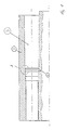
- a cartridge chamber 6 and parts thereof is shown in a sectional view.
- a defined groove 5 is introduced in the cartridge chamber 6.
- the position and shape of the groove 5 in the cartridge chamber 6 is matched to the geometry and nature of a cartridge 3 not shown here or its sleeve 2 (see FIG. 2). 1, the bearing housing of the cartridge chamber 6 is marked.
- FIG. 1 a shows an enlarged detail A of FIG. 1 for a clear illustration of the groove 5.
- FIG. 2 the cartridge chamber 6 is shown with the here indicated cartridge 3 with sleeve 2.
- an ejector 8 here an extractor, by means of which the sleeve 2 is transported from the cartridge chamber 6.
- FIG. 2 a shows an enlarged detail A 'of FIG. 2, which is identical in principle to the geometric detail A of FIG. 1.
- the gas pressure in the cartridge case 2 deforms it on the housing 4 in such a way that it engages in the groove 5 by permanent deformations 7.
- the extractor 8 When attaching the extractor 8, ie, when pulling out the sleeve 2, the extractor 8 must apply so much force or tension that deformed in the grooves 5 housing 4 of the sleeve 2 via the deformation path X from the groove 5 and the chamber 6 is pulled out. This build-up of tension guarantees a higher, predefinable voltage level with a significantly reduced bandwidth.
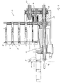
- Fig. 3 the principle of the sleeve return is shown, with only the essential parts of the invention were identified.
- 10 with a here shown excerpt conveyor is marked, which transported in this representation pods 2 of the lost ammunition 3 (not visible here).
- the sleeves 2 are transferred by an arms-side extractor 8 in an ejection position 23 (Fig. 4) in an ejector tube marked 12.
- This ejection tube 12 is preferably in the housing of a Munitionszu réelles 13, which is usually part of a weapon, not shown, involved.
- this ejector tube 12 With this ejector tube 12 in functional accordance standing, there is a designated 14 sleeve damper, which dampens the ejected at very high speed sleeves 2.
- the sleeve damper 14 For trouble-free operation of the sleeve damper 14 is brought after each shot in its original position. If the sleeve damper 14 is a spring damping system, this can here positively controlled by its own spring force in the starting position are performed. This forced control is also possible via a cam wheel with control cam (not shown in detail), which can be integrated in the transmission 15 of the ammunition feeder 13 itself.
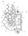
- FIG. 4 shows a view of the interaction of ammunition transport and tube removal.
- the ammunition chain 10 'conveys cartridges 3 from a non-illustrated ammunition container into the ammunition feeder 13 of the weapon.
- the cartridges or ammunition 3 is held in the chain links 18 and guided in the region of the sprocket 19 of the conveyor 10.
- the cartridge 3 is then transferred in the area of the sprocket 19 to a gun-side rotor 20 of the ammunition feeder 13 and in this position by the rotor 20 to a weapon-side feed star 21.
- This feed star 21 has here due to the number of drums five notches and associated five positions for the ammunition 3. Further positions are the actual firing position 22 and the ejection position 23 of the sleeve 2.
- this ejection position 23 in functionality is, as already described, the ejection tube 12, which guides the sleeves 2 in a sleeve-catching position 24 along a sleeve lead 25.
- a sensor 26 is used inter alia for functional testing.
- the sleeve damper 14 here a spring system, springs in and reduces the collection energy of the sleeve 2.
- the stroke of the sleeve damper 14 is designed so that the sleeve 2 are caught by the sleeve catch springs 28 on the withdrawal edge 27 of the sleeve 2.
- the sleeve 2 is thereby defined in the ammunition chain 10 '.
- the next shot the system is rotated further and the sleeve 2 is returned via the ammunition chain 10 'in the ammunition container.
- the reset of the sleeve damper 14 is preferably realized in this embodiment by the energy in the own springs. The same procedure also applies to a failure failure.
- the weapon with the ammunition feeder 7 makes up to approx. 40 mm return and forward movements, the weapon is mounted in a returning system (not shown in detail) in a damped manner. Since the ammunition container is usually rigidly mounted, the transfer of the cartridge 3 via a flexible configuration of the conveyor 10 takes place.
Landscapes
- Engineering & Computer Science (AREA)
- General Engineering & Computer Science (AREA)
- Portable Nailing Machines And Staplers (AREA)
- Casting Support Devices, Ladles, And Melt Control Thereby (AREA)
- Feeding And Guiding Record Carriers (AREA)
- Pens And Brushes (AREA)
- Mechanical Pencils And Projecting And Retracting Systems Therefor, And Multi-System Writing Instruments (AREA)
Abstract
Description
- Bei Waffen, welche in erster Linie in Trägern, wie Fahr- und Flugzeugen, eingebaut sind, gibt es oftmals Probleme mit dem Hülsenauswurf. Vor allem dann, wenn die Hülse beim Schießen in schwer zugängliche Auffangbehälter und in genau definierten Positionen geworfen werden sollen. Aufgrund von notwendigen Führungskanälen und Hülsenumlenkungen kann die Hülse auf dem Weg zu ihrer Endposition in ihrer Flugzeit bzw. Fluggeschwindigkeit stark abgebremst werden. Beim Schießen kommt es dann zu Störungen, welche durch die undefinierte Positionen der Hülsen oder durch ihr Liegenbleiben auf dem Weg zu ihrer Endposition hervorgerufen wird. Es entstehen Hülsenstaus oder aber die Hülsen sind nicht in der richtigen Abführposition im Munitionstransportsystem. Die Auswurfgeschwindigkeit ist stark abhängig vom Liderungscharakter der Patronen bzw. Hülsen nach dem Schuß im Patronenlager.
- Aus der DE 689 05 739 T2 (EP 0 362 064 B1) ist eine Schnellfeuer - Revolverwaffe bekannt, bei dem zum Zurückführen der leeren Patronenhülse ein Auswerfer vorgesehen ist, durch den die Hülse aus dem Revolverkopf geführt und entlang einer Rutsche getrieben wird. Der Auswerfer greift dazu mittels einer Nase an der Bodennut der Hülse an.
- Die Liderung wird bekanntlich stark beeinflußt vom Gasdruck der Patrone, dem Patronenlagerzustand, wie Reibung, Schmierung, Verschmutzung und Korrosion, von der Hülsenbeschaffenheit, wie beispielsweise die Härte der Hülse, die Beschichtung der Hülse oder aber das Toleranzfeld. Weitere Einflußgrößen sind der Zustand der Auswurfmechanik sowie die Verschmutzung durch Mündungsbremsen.
- Unter den bereits aufgeführten Situationen kann es auch bei der vorgenannten Verwendung eines Auswerfers zu Hülsenauswurfstörungen kommen. Die Hülsen erreichen nicht die sogenannte Fangposition im Munitionstransportsystem.
- Hier stellt sich die Erfindung die Aufgabe, eine Möglichkeit für einen definierten Auswurf zu schaffen, um zu verhindern, dass es zu einem Hülsenstau etc. kommt.
- Der Erfindung liegt die Idee zugrunde, da die aufgezählten Beeinflussungsgrößen für die Liderung fertigungstechnischer als auch schießtechnischer Natur und daher mehr oder weniger unveränderbar sind, ein Patronenlager mit einem definierten Hülsenausziehwiderstand zu konzipieren. Dieser wird durch eine Mindestliderung geschaffen, die im Patronenlager integriert wird. Beim Auswurfvorgang wird die Entspannungsenergie genutzt und diese beim Lösen der Hülse entsprechend in eine Geschwindigkeit umgesetzt. Es wird eine Mindestspannung aufgebaut, was zur Folge hat, dass eine Vorspannung gesichert ist, so dass keine Geschwindigkeitsreduzierungen der Hülsen auftreten.
- Dazu ist vorgesehen, wenigstens eine Rille in das Patronenlager im vorderen Bereich einer Hülse einer Patrone einzubringen. Die Praxis hat gezeigt, dass eine Rille als ausreichend anzusehen ist, wobei auch mehr als eine möglich sind. Die einzelne Rille kann dabei über den gesamten Innenumfang (d.h., rundum) des Gehäuses des Patronenlagers oder aber nur in bestimmten Abschnitten des Innenumfangs eingebracht sein. Letzteres bietet sich unter anderem dann an, wenn mehr als eine Rille vorgesehen werden.
- Anwendung findet die Lösung u.a. in hochkandenten Waffen mit einem gurtgliedlosen Munitionstransportsystem. Hierbei werden die abgeschossenen bzw. einem Trommelpatronenlager ausgeworfenen Hülsen über einen Puffer gedämpft in einem Kettensystem gefangen, genau positioniert und in eine Munitionsbox transportiert. Durch die definierte Auszugsspannung wird der sonst bekannte Fehler, der bei derartigen Systemen auftritt vermieden. Es wird verhindert, dass die Hülse auf ihrem Weg zur Fangposition abgebremst bzw. nicht mit einer Mindestgeschwindigkeit ausgeworfen wird, da in solchen Fällen das Munitionstransportsystem, über die Waffe gesteuert, beim nachfolgenden Schuss schon weiter dreht, bevor die Hülse ihre Sollposition erreicht hat.
- Anhand eines Ausführungsbeispiels soll die Lösung näher erläutert werden. Es zeigt:
- Fig. 1
- ein Patronenlager in Schnittdarstellung ohne Hülse,
- Fig. 1 a
- eine Ausschnittdarstellung A aus Fig. 1,
- Fig. 2
- das Patronenlager mit Hülse,
- Fig. 2a
- die Ausschnittsdarstellung A' aus Fig. 2
- Fig. 3
- in einer Schnittdarstellung die Rückführung einer Hülse in eine Munitionskette,
- Fig. 4
- in einer Schnittdarstellung die Munitionsübergabe und die Hülsenübernahme zwischen Munitionskette und Waffentrommel.
- In Fig. 1 ist ein Patronenlager 6 bzw. Teile davon in einer Schnittdarstellung dargestellt. Im Patronenlager 6 ist eine definierte Rille 5 eingebracht. Die Position und die Form der Rille 5 im Patronenlager 6 ist auf die Geometrie und Beschaffenheit einer hier nicht näher dargestellten Patrone 3 bzw. ihrer Hülse 2 (siehe Fig. 2) abgestimmt. Mit 1 ist das Lagergehäuse des Patronenlagers 6 gekennzeichnet.
- Fig. 1 a zeigt einen vergrößerten Ausschnitt A der Fig. 1 zur deutlichen Darstellung der Rille 5.
- In Fig. 2 ist das Patronenlager 6 mit der hier angedeuteten Patrone 3 mit Hülse 2 dargestellt. An den Boden der Hülse 2 greift ein Auswerfersystem 8, hier ein Auszieher an, mit dessen Hilfe die Hülse 2 aus dem Patronenlager 6 transportiert wird.
- Fig. 2a zeigt einen vergrößerten Ausschnitt A' der Fig. 2, der im Prinzip mit dem geometrischen Ausschnitt A aus Fig. 1 identisch ist. Beim Schuß wird durch den Gasdruck in der Patronenhülse 2 diese am Gehäuse 4 so verformt, dass sie sich durch bleibende Verformungen 7 in der Rille 5 anlegt. Beim Ansetzen des Ausziehers 8, d.h., beim Ausziehen der Hülse 2, muss der Auszieher 8 so viel Kraft bzw. Spannung aufwenden, dass das in den Rillen 5 verformte Gehäuse 4 der Hülse 2 über den Verformungsweg X aus der Rille 5 bzw. dem Patronenlager 6 herausgezogen wird. Dieser Spannungsaufbau garantiert ein höheres, vordefinierbares Spannungsniveau mit einer wesentlich verkleinerten Bandbreite.
- Es wird ein gezielter Spannungsaufbau zwischen der Hülse 2, dem Patronenlager 6 und einem Auswerfersystem 8 erreicht.
- In Fig. 3 ist das Prinzip der Hülsenrückführung dargestellt, wobei nur die erfindungswesentlichen Teile kenntlich gemacht wurden.
Mit 10 ist ein hier auszugsweise dargestellter Conveyor gekennzeichnet, welche in dieser Darstellung Hülsen 2 der verschossenen Munition 3 (hier nicht erkennbar) abtransportiert. Die Hülsen 2 werden durch einen waffenseitigen Auszieher 8 in einer Auswurfposition 23 (Fig. 4) in ein mit 12 gekennzeichneten Auswurfrohr überführt. Dieses Auswurfrohr 12 ist vorzugsweise im Gehäuse eines Munitionszuführers 13, welcher in der Regel Bestandteil einer nicht näher dargestellten Waffe ist, eingebunden. Mit diesem Auswurfrohr 12 in funktionalem Einklang stehend, befindet sich ein mit 14 gekennzeichneter Hülsendämpfer, welcher die mit sehr hoher Geschwindigkeit ausgeworfenen Hülsen 2 abdämpft. Für einen störungsfreien Funktionsablauf wird der Hülsendämpfer 14 nach jedem Schuss in seine Ausgangslage gebracht. Ist der Hülsendämpfer 14 ein Federdämpfungssystem, kann dieser hier zwangsgesteuert durch die eigene Federkraft in die Ausgangslage geführt werden. Diese Zwangssteuerung ist aber auch über ein Nockenrad mit Steuernocken (nicht näher dargestellt) möglich, welches selbst im Getriebe 15 des Munitionszuführers 13 integriert sein kann. - Fig. 4 zeigt in einer Ansicht das Zusammenspiel Munitionstransport und Hülsenabtransport.
- In bekannter Art und Weise treibt das Getriebe 15 mittels der Trommelachse 16 der Waffe über die Conveyorachse 17 die Munitionskette 10' für die Munitionszuführung und Hülsenabführung an.
- Die Munitionskette 10' fördert aus einem nicht näher dargestellten Munitionsbehälter Patronen 3 in den Munitionszuführer 13 der Waffe. Die Patronen bzw. die Munition 3 wird in den Kettengliedern 18 gehalten und in den Bereich des Kettenrades 19 des Conveyors 10 geführt. Die Patrone 3 wird danach im Bereich des Kettenrades 19 einem waffenseitigen Rotor 20 des Munitionszuführers 13 und in dieser Position durch den Rotor 20 einem waffenseitigen Zuführstern 21 übergeben. Dieser Zuführstern 21 weist hier bedingt durch die Trommelanzahl fünf Einkerbungen und damit verbunden fünf Positionen für die Munition 3 auf. Weitere Positionen sind die eigentliche Schussposition 22 und die Auswurfposition 23 der Hülse 2.
- Mit dieser Auswurfposition 23 in Funktionalität stehend ist, wie bereits beschrieben, das Auswurfrohr 12, das die Hülsen 2 in eine Hülsenfangposition 24 entlang einer Hülsenableitung 25 führt. Ein Sensor 26 dient unter anderem zur Funktionsprüfung.
- Nach Abfeuern der Patrone 3 aus der Schussposition 22 dreht die Trommel der Waffe und die Hülse 2 wird mittels Auszieher 8 aus dem Patronenlager 6 gezogen und ausgeworfen. Die mit hoher Geschwindigkeit ausgeworfene Hülse 2 wird über das Auswurfrohr 12 zu Hülsenfangfedern 28 geleitet. Beim Auftreffen der Hülse 2 auf die Hülsenfangfedern 28 wird der Hülsenpuffer bzw. Hülsendämpfer 14 mit der Hülse 2 beaufschlagt. Der Hülsendämpfer 14, hier ein Federsystem, federt ein und reduziert die Auffangenergie der Hülse 2. Der Hub des Hülsendämpfers 14 ist so ausgelegt, dass die Hülse 2 durch die Hülsenfangfedern 28 am Ausziehrand 27 der Hülse 2 gefangen werden. Die Hülse 2 liegt dadurch definiert in der Munitionskette 10'. Beim nächsten Schuss wird das System weiter gedreht und die Hülse 2 über die Munitionskette 10' in den Munitionsbehälter zurückgeführt. Das Zurückstellen des Hülsendämpfers 14 wird in diesem Ausführungsbeispiel vorzugsweise durch die Energie in den eigenen Federn realisiert.
Selbiger Ablauf gilt auch bei einem Zündversager. - Um die beim Schuss auftretenden Rückstoß- und Vorlaufkräfte zu reduzieren, d.h., die Waffe mit dem Munitionszuführer 7 macht bis zu ca. 40 mm Rücklauf- und Vorlaufbewegungen, ist die Waffe in einem rücklaufenden System (nicht näher dargestellt) gedämpft gelagert. Da der Munitionsbehälter in der Regel starr montiert ist, erfolgt die Übergabe der Patrone 3 über eine flexible Ausgestaltung des Conveyors 10.
-
- 1
- Lagergehäuse
- 2
- Hülse
- 3
- Patrone
- 4
- Gehäuse der Hülse
- 5
- Rille
- 6
- Patronenlager
- 8
- Auswerfersystem
- 10
- Conveyor
- 10'
- Munitionskette
- 12
- Auswurfrohr
- 13
- Munitionszuführer
- 14
- Hülsendämpfer
- 15
- Getriebe
- 16
- Trommelachse
- 17
- Conveyorachse
- 18
- Kettenglieder
- 19
- Kettenrad, zur Waffe weisend
- 20
- Rotor
- 21
- Zuführstern
- 22
- Schussposition
- 23
- Auswurfposition
- 24
- Hülsenfangposition
- 25
- Hülsenableitung
- 26
- Sensor
- 28
- Hülsenfangfedern
Claims (9)
- Vorrichtung zum definierten Auswurf einer Hülse oder Munition aus einem Patronenlager (6) einer Waffe, mit einem Auswerfersystem (8) zum Transportieren einer von einer Patrone (3) durch Verschuß befreiten Hülse (2) oder einem Zündversager (Patrone) aus dem Patronenlager (6), wobei wenigstens eine definierte Rille (5) in das Innere des Gehäuses (1) des Patronenlager (6) eingebracht ist, und die Position und die Form der Rille (5) auf die Geometrie und Beschaffenheit der Hülse (2) abgestimmt ist.
- Vorrichtung nach Anspruch 1, dadurch gekennzeichnet, dass beim Verschuß der Patrone (3) die Hülse (2) in ihrem Gehäuse (4) so verformt wird, dass die Hülse (2) sich durch bleibende Verformungen (7) in der Rille (5) anlegt.
- Vorrichtung nach Anspruch 2, dadurch gekennzeichnet, dass beim Ansetzen des Auswerfersystems (8) dieser so viel Kraft bzw. Spannung aufwendet, dass das in den Rillen (5) verformte Gehäuse (4) der Hülse (2) über einen Verformungsweg (X) aus der Rille (5) des Patronenlagers (6) herausgezogen wird.
- Vorrichtung nach einem der Ansprüche 1 bis 3, dadurch gekennzeichnet, dass die Rille (5) im gesamten Innenumfang des Patronenlagers (6) eingebunden ist.
- Vorrichtung nach einem der Ansprüche 1 bis 3, dadurch gekennzeichnet, dass die Rille (5) unterbrochen und dadurch teilweise im Innenumfang des Patronenlagers (6) eingebracht ist.
- Vorrichtung nach einem der vorgenannten Ansprüche, dadurch gekennzeichnet, dass eine Hülsenfangeinrichtung eingebunden ist.
- Vorrichtung nach Anspruch 6, dadurch gekennzeichnet, dass die Hülsenfangeinrichtung ein Auswurfrohr (12) und einen Hülsendämpfer (14) aufweist, der mit dem Auswurfrohr (12) in funktionalem Zusammenhang steht, wobei die über einen zum Auswerfersystem (4) zugehörigen Auszieher (11) mit hoher Geschwindigkeit aus dem Patronenlager (6) gezogene Hülse (2) oder Patrone (3) über das Auswurfrohr (12) zu Hülsenfangfedern (28), die sich zwischen dem Auswurfrohr (12) und dem Hülsendämpfer (14) befinden, geleitet werden, so dass beim Auftreffen der Hülse (2) oder Patrone (3) auf die Hülsenfangfedern (28) der Hülsendämpfer (14) mit der Hülse (2) oder Patrone (3) beaufschlagt und die Auffangenergie reduziert wird.
- Vorrichtung nach Anspruch 6 oder 7, dadurch gekennzeichnet, dass der Hülsendämpfer (8) Hydraulik-, Massen- oder Federdämpfungssystem ist.
- Vorrichtung nach einem der Ansprüche 6 bis 8, dadurch gekennzeichnet, dass der Hub des Hülsendämpfers (8) so ausgelegt ist, dass die Hülse (2) oder Patrone (3) durch die Hülsenfangfedern (21) am Ausziehrand (22) der Hülse (2) gefangen werden und dadurch definiert in der Munitionskette (1) zum Liegen kommt.
Applications Claiming Priority (1)
| Application Number | Priority Date | Filing Date | Title |
|---|---|---|---|
| DE102005003752A DE102005003752B4 (de) | 2005-01-27 | 2005-01-27 | Vorrichtung zum definierten Auswurf einer Hülse oder Munition aus einem Patronenlager |
Publications (2)
| Publication Number | Publication Date |
|---|---|
| EP1686345A1 true EP1686345A1 (de) | 2006-08-02 |
| EP1686345B1 EP1686345B1 (de) | 2008-10-08 |
Family
ID=36061635
Family Applications (1)
| Application Number | Title | Priority Date | Filing Date |
|---|---|---|---|
| EP05024767A Expired - Lifetime EP1686345B1 (de) | 2005-01-27 | 2005-11-12 | Vorrichtung zum definierten Auswurf einer Hülse oder Munition aus einem Patronenlager |
Country Status (3)
| Country | Link |
|---|---|
| EP (1) | EP1686345B1 (de) |
| AT (1) | ATE410657T1 (de) |
| DE (2) | DE102005003752B4 (de) |
Cited By (1)
| Publication number | Priority date | Publication date | Assignee | Title |
|---|---|---|---|---|
| WO2015007440A1 (de) * | 2013-07-17 | 2015-01-22 | Rheinmetall Waffe Munition Gmbh | Hülsenauswurfvorrichtung und waffe mit einer derartigen vorrichtung |
Families Citing this family (1)
| Publication number | Priority date | Publication date | Assignee | Title |
|---|---|---|---|---|
| DE102024118062A1 (de) | 2024-06-26 | 2025-12-31 | Rheinmetall Waffe Munition Gmbh | Verfahren zur Analyse einer Hülse, Patronenlager einer Feuerwaffe und Feuerwaffe |
Citations (3)
| Publication number | Priority date | Publication date | Assignee | Title |
|---|---|---|---|---|
| US3609904A (en) * | 1969-05-07 | 1971-10-05 | Remington Arms Co Inc | Extractable plastic cartridge |
| CH581305A5 (en) * | 1974-02-20 | 1976-10-29 | Bofors Ab | Flangeless plastics cartridge case for firearms - is withdrawn by breech block after firing by keying effect |
| EP0362064B1 (de) | 1988-09-28 | 1993-03-31 | GIAT Industries | Automatische Schnellfeuer-Revolverwaffe |
Family Cites Families (2)
| Publication number | Priority date | Publication date | Assignee | Title |
|---|---|---|---|---|
| US3059367A (en) * | 1961-02-23 | 1962-10-23 | Rosebush F Ward | Compensating means in barrel chamber for low and high powered cartridges |
| CH667325A5 (en) * | 1985-09-26 | 1988-09-30 | Oerlikon Buehrle Ag | Firearm empty case-collection accessory - comprises spring impact lever with damper before shaft leading to bag |
-
2005
- 2005-01-27 DE DE102005003752A patent/DE102005003752B4/de not_active Expired - Fee Related
- 2005-11-12 EP EP05024767A patent/EP1686345B1/de not_active Expired - Lifetime
- 2005-11-12 AT AT05024767T patent/ATE410657T1/de not_active IP Right Cessation
- 2005-11-12 DE DE502005005609T patent/DE502005005609D1/de not_active Expired - Lifetime
Patent Citations (4)
| Publication number | Priority date | Publication date | Assignee | Title |
|---|---|---|---|---|
| US3609904A (en) * | 1969-05-07 | 1971-10-05 | Remington Arms Co Inc | Extractable plastic cartridge |
| CH581305A5 (en) * | 1974-02-20 | 1976-10-29 | Bofors Ab | Flangeless plastics cartridge case for firearms - is withdrawn by breech block after firing by keying effect |
| EP0362064B1 (de) | 1988-09-28 | 1993-03-31 | GIAT Industries | Automatische Schnellfeuer-Revolverwaffe |
| DE68905739T2 (de) | 1988-09-28 | 1993-07-08 | Giat Ind Sa | Automatische schnellfeuer-revolverwaffe. |
Cited By (1)
| Publication number | Priority date | Publication date | Assignee | Title |
|---|---|---|---|---|
| WO2015007440A1 (de) * | 2013-07-17 | 2015-01-22 | Rheinmetall Waffe Munition Gmbh | Hülsenauswurfvorrichtung und waffe mit einer derartigen vorrichtung |
Also Published As
| Publication number | Publication date |
|---|---|
| DE102005003752A1 (de) | 2006-08-10 |
| DE502005005609D1 (de) | 2008-11-20 |
| DE102005003752B4 (de) | 2008-07-17 |
| EP1686345B1 (de) | 2008-10-08 |
| ATE410657T1 (de) | 2008-10-15 |
Similar Documents
| Publication | Publication Date | Title |
|---|---|---|
| DE102009041094A1 (de) | Waffe, insbesondere reichweitengesteuerte Druckluftwaffe | |
| DE4315829A1 (de) | Manöverpatronengerät | |
| EP1686345B1 (de) | Vorrichtung zum definierten Auswurf einer Hülse oder Munition aus einem Patronenlager | |
| EP1686344B1 (de) | Hülsenauffangeinrichtung für eine gurtgliedlose Munition | |
| DE3050016C2 (de) | Zweistufen-Granatenzufuhrgerät mit Granatenzufuhrpfadsteuerung | |
| DE4135273C2 (de) | Ansetzerkopf mit integriertem Auszieher für Munition | |
| DE4105271C1 (de) | ||
| DE102016012145B4 (de) | Revolverkanone und Verfahren zum Betrieb einer Revolverkanone | |
| DE102017107442B4 (de) | Vorrichtung zum Laden einer Rohrwaffe mit Munitionskörpern | |
| EP2260261A1 (de) | Treibkäfiggeschoss | |
| EP2739931B1 (de) | Manöverpatroneneinrichtung und hierfür geeignete selbstlade-feuerwaffe | |
| EP2800938B1 (de) | Verfahren und vorrichtung zur erkennung einer geschossvorlage | |
| EP3477240B1 (de) | Momentfreier gasantrieb für eine feuerwaffe | |
| DE4009050C2 (de) | ||
| EP2697592A1 (de) | VERFAHREN ZUM KADENZMÄßIGEN LADEN EINER WAFFE | |
| DE4341855A1 (de) | Verbesserung bei der Bewegung von Teilen | |
| EP3320294A1 (de) | Hülsenauswurfvorrichtung | |
| WO2020173869A1 (de) | Luftenergiepatrone | |
| EP3017271B1 (de) | Aus einem drallstabilisierten trägergeschoss ausstossbare submunition, insbesondere leuchtmunition | |
| DE19923513C2 (de) | Ladevorrichtung für eine Schußwaffe, sowie Schußwaffe hiermit | |
| DE19818714C2 (de) | Blockiervorrichtung für bewegliche Anschlüsse von Schalldämpfern an halbautomatischen Waffen | |
| EP2391861B1 (de) | Schnellstopp für eine maschinenkanone | |
| EP2191222B1 (de) | Geschützrohr zum verschiessen drallstabilisierter geschosse | |
| DE102020106157A1 (de) | Vorrichtung zur Sicherung einer Munition oder Treibladung sowie Waffenanlage mit einer derartigen Vorrichtung | |
| EP3486601A1 (de) | Reinigungsvorrichtung für einen lauf einer waffe |
Legal Events
| Date | Code | Title | Description |
|---|---|---|---|
| PUAI | Public reference made under article 153(3) epc to a published international application that has entered the european phase |
Free format text: ORIGINAL CODE: 0009012 |
|
| AK | Designated contracting states |
Kind code of ref document: A1 Designated state(s): AT BE BG CH CY CZ DE DK EE ES FI FR GB GR HU IE IS IT LI LT LU LV MC NL PL PT RO SE SI SK TR |
|
| AX | Request for extension of the european patent |
Extension state: AL BA HR MK YU |
|
| 17P | Request for examination filed |
Effective date: 20061208 |
|
| 17Q | First examination report despatched |
Effective date: 20070111 |
|
| AKX | Designation fees paid |
Designated state(s): AT BE BG CH CY CZ DE DK EE ES FI FR GB GR HU IE IS IT LI LT LU LV MC NL PL PT RO SE SI SK TR |
|
| GRAP | Despatch of communication of intention to grant a patent |
Free format text: ORIGINAL CODE: EPIDOSNIGR1 |
|
| GRAS | Grant fee paid |
Free format text: ORIGINAL CODE: EPIDOSNIGR3 |
|
| GRAA | (expected) grant |
Free format text: ORIGINAL CODE: 0009210 |
|
| AK | Designated contracting states |
Kind code of ref document: B1 Designated state(s): AT BE BG CH CY CZ DE DK EE ES FI FR GB GR HU IE IS IT LI LT LU LV MC NL PL PT RO SE SI SK TR |
|
| REG | Reference to a national code |
Ref country code: GB Ref legal event code: FG4D Free format text: NOT ENGLISH |
|
| REG | Reference to a national code |
Ref country code: CH Ref legal event code: EP |
|
| RAP2 | Party data changed (patent owner data changed or rights of a patent transferred) |
Owner name: RHEINMETALL WAFFE MUNITION GMBH |
|
| REG | Reference to a national code |
Ref country code: IE Ref legal event code: FG4D Free format text: LANGUAGE OF EP DOCUMENT: GERMAN |
|
| REF | Corresponds to: |
Ref document number: 502005005609 Country of ref document: DE Date of ref document: 20081120 Kind code of ref document: P |
|
| NLT2 | Nl: modifications (of names), taken from the european patent patent bulletin |
Owner name: RHEINMETALL WAFFE MUNITION GMBH Effective date: 20081022 |
|
| PG25 | Lapsed in a contracting state [announced via postgrant information from national office to epo] |
Ref country code: SI Free format text: LAPSE BECAUSE OF FAILURE TO SUBMIT A TRANSLATION OF THE DESCRIPTION OR TO PAY THE FEE WITHIN THE PRESCRIBED TIME-LIMIT Effective date: 20081008 |
|
| NLV1 | Nl: lapsed or annulled due to failure to fulfill the requirements of art. 29p and 29m of the patents act | ||
| PG25 | Lapsed in a contracting state [announced via postgrant information from national office to epo] |
Ref country code: LT Free format text: LAPSE BECAUSE OF FAILURE TO SUBMIT A TRANSLATION OF THE DESCRIPTION OR TO PAY THE FEE WITHIN THE PRESCRIBED TIME-LIMIT Effective date: 20081008 Ref country code: BG Free format text: LAPSE BECAUSE OF FAILURE TO SUBMIT A TRANSLATION OF THE DESCRIPTION OR TO PAY THE FEE WITHIN THE PRESCRIBED TIME-LIMIT Effective date: 20090108 Ref country code: ES Free format text: LAPSE BECAUSE OF FAILURE TO SUBMIT A TRANSLATION OF THE DESCRIPTION OR TO PAY THE FEE WITHIN THE PRESCRIBED TIME-LIMIT Effective date: 20090119 |
|
| PG25 | Lapsed in a contracting state [announced via postgrant information from national office to epo] |
Ref country code: PT Free format text: LAPSE BECAUSE OF FAILURE TO SUBMIT A TRANSLATION OF THE DESCRIPTION OR TO PAY THE FEE WITHIN THE PRESCRIBED TIME-LIMIT Effective date: 20090218 Ref country code: LV Free format text: LAPSE BECAUSE OF FAILURE TO SUBMIT A TRANSLATION OF THE DESCRIPTION OR TO PAY THE FEE WITHIN THE PRESCRIBED TIME-LIMIT Effective date: 20081008 Ref country code: NL Free format text: LAPSE BECAUSE OF FAILURE TO SUBMIT A TRANSLATION OF THE DESCRIPTION OR TO PAY THE FEE WITHIN THE PRESCRIBED TIME-LIMIT Effective date: 20081008 Ref country code: IS Free format text: LAPSE BECAUSE OF FAILURE TO SUBMIT A TRANSLATION OF THE DESCRIPTION OR TO PAY THE FEE WITHIN THE PRESCRIBED TIME-LIMIT Effective date: 20090208 Ref country code: FI Free format text: LAPSE BECAUSE OF FAILURE TO SUBMIT A TRANSLATION OF THE DESCRIPTION OR TO PAY THE FEE WITHIN THE PRESCRIBED TIME-LIMIT Effective date: 20081008 Ref country code: PL Free format text: LAPSE BECAUSE OF FAILURE TO SUBMIT A TRANSLATION OF THE DESCRIPTION OR TO PAY THE FEE WITHIN THE PRESCRIBED TIME-LIMIT Effective date: 20081008 |
|
| BERE | Be: lapsed |
Owner name: RHEINMETALL WAFFE MUNITION G.M.B.H. Effective date: 20081130 |
|
| PG25 | Lapsed in a contracting state [announced via postgrant information from national office to epo] |
Ref country code: MC Free format text: LAPSE BECAUSE OF NON-PAYMENT OF DUE FEES Effective date: 20081130 |
|
| REG | Reference to a national code |
Ref country code: IE Ref legal event code: FD4D |
|
| PG25 | Lapsed in a contracting state [announced via postgrant information from national office to epo] |
Ref country code: RO Free format text: LAPSE BECAUSE OF FAILURE TO SUBMIT A TRANSLATION OF THE DESCRIPTION OR TO PAY THE FEE WITHIN THE PRESCRIBED TIME-LIMIT Effective date: 20081008 Ref country code: IE Free format text: LAPSE BECAUSE OF FAILURE TO SUBMIT A TRANSLATION OF THE DESCRIPTION OR TO PAY THE FEE WITHIN THE PRESCRIBED TIME-LIMIT Effective date: 20081008 Ref country code: DK Free format text: LAPSE BECAUSE OF FAILURE TO SUBMIT A TRANSLATION OF THE DESCRIPTION OR TO PAY THE FEE WITHIN THE PRESCRIBED TIME-LIMIT Effective date: 20081008 Ref country code: EE Free format text: LAPSE BECAUSE OF FAILURE TO SUBMIT A TRANSLATION OF THE DESCRIPTION OR TO PAY THE FEE WITHIN THE PRESCRIBED TIME-LIMIT Effective date: 20081008 |
|
| PLBE | No opposition filed within time limit |
Free format text: ORIGINAL CODE: 0009261 |
|
| STAA | Information on the status of an ep patent application or granted ep patent |
Free format text: STATUS: NO OPPOSITION FILED WITHIN TIME LIMIT |
|
| PG25 | Lapsed in a contracting state [announced via postgrant information from national office to epo] |
Ref country code: CZ Free format text: LAPSE BECAUSE OF FAILURE TO SUBMIT A TRANSLATION OF THE DESCRIPTION OR TO PAY THE FEE WITHIN THE PRESCRIBED TIME-LIMIT Effective date: 20081008 Ref country code: SE Free format text: LAPSE BECAUSE OF FAILURE TO SUBMIT A TRANSLATION OF THE DESCRIPTION OR TO PAY THE FEE WITHIN THE PRESCRIBED TIME-LIMIT Effective date: 20090108 Ref country code: IT Free format text: LAPSE BECAUSE OF FAILURE TO SUBMIT A TRANSLATION OF THE DESCRIPTION OR TO PAY THE FEE WITHIN THE PRESCRIBED TIME-LIMIT Effective date: 20081008 |
|
| 26N | No opposition filed |
Effective date: 20090709 |
|
| PG25 | Lapsed in a contracting state [announced via postgrant information from national office to epo] |
Ref country code: BE Free format text: LAPSE BECAUSE OF NON-PAYMENT OF DUE FEES Effective date: 20081130 Ref country code: SK Free format text: LAPSE BECAUSE OF FAILURE TO SUBMIT A TRANSLATION OF THE DESCRIPTION OR TO PAY THE FEE WITHIN THE PRESCRIBED TIME-LIMIT Effective date: 20081008 |
|
| PG25 | Lapsed in a contracting state [announced via postgrant information from national office to epo] |
Ref country code: AT Free format text: LAPSE BECAUSE OF NON-PAYMENT OF DUE FEES Effective date: 20081112 |
|
| REG | Reference to a national code |
Ref country code: CH Ref legal event code: PL |
|
| PG25 | Lapsed in a contracting state [announced via postgrant information from national office to epo] |
Ref country code: HU Free format text: LAPSE BECAUSE OF FAILURE TO SUBMIT A TRANSLATION OF THE DESCRIPTION OR TO PAY THE FEE WITHIN THE PRESCRIBED TIME-LIMIT Effective date: 20090409 Ref country code: LU Free format text: LAPSE BECAUSE OF NON-PAYMENT OF DUE FEES Effective date: 20081112 Ref country code: CY Free format text: LAPSE BECAUSE OF FAILURE TO SUBMIT A TRANSLATION OF THE DESCRIPTION OR TO PAY THE FEE WITHIN THE PRESCRIBED TIME-LIMIT Effective date: 20081008 |
|
| PG25 | Lapsed in a contracting state [announced via postgrant information from national office to epo] |
Ref country code: TR Free format text: LAPSE BECAUSE OF FAILURE TO SUBMIT A TRANSLATION OF THE DESCRIPTION OR TO PAY THE FEE WITHIN THE PRESCRIBED TIME-LIMIT Effective date: 20081008 |
|
| PG25 | Lapsed in a contracting state [announced via postgrant information from national office to epo] |
Ref country code: LI Free format text: LAPSE BECAUSE OF NON-PAYMENT OF DUE FEES Effective date: 20091130 Ref country code: GR Free format text: LAPSE BECAUSE OF FAILURE TO SUBMIT A TRANSLATION OF THE DESCRIPTION OR TO PAY THE FEE WITHIN THE PRESCRIBED TIME-LIMIT Effective date: 20090109 Ref country code: CH Free format text: LAPSE BECAUSE OF NON-PAYMENT OF DUE FEES Effective date: 20091130 |
|
| PGFP | Annual fee paid to national office [announced via postgrant information from national office to epo] |
Ref country code: GB Payment date: 20101118 Year of fee payment: 6 |
|
| PGFP | Annual fee paid to national office [announced via postgrant information from national office to epo] |
Ref country code: FR Payment date: 20111130 Year of fee payment: 7 |
|
| GBPC | Gb: european patent ceased through non-payment of renewal fee |
Effective date: 20121112 |
|
| REG | Reference to a national code |
Ref country code: FR Ref legal event code: ST Effective date: 20130731 |
|
| PG25 | Lapsed in a contracting state [announced via postgrant information from national office to epo] |
Ref country code: GB Free format text: LAPSE BECAUSE OF NON-PAYMENT OF DUE FEES Effective date: 20121112 Ref country code: FR Free format text: LAPSE BECAUSE OF NON-PAYMENT OF DUE FEES Effective date: 20121130 |
|
| PGFP | Annual fee paid to national office [announced via postgrant information from national office to epo] |
Ref country code: DE Payment date: 20141119 Year of fee payment: 10 |
|
| REG | Reference to a national code |
Ref country code: DE Ref legal event code: R119 Ref document number: 502005005609 Country of ref document: DE |
|
| PG25 | Lapsed in a contracting state [announced via postgrant information from national office to epo] |
Ref country code: DE Free format text: LAPSE BECAUSE OF NON-PAYMENT OF DUE FEES Effective date: 20160601 |