EP1686277B1 - Doppelkupplung mit gleichgrossen Lamellen - Google Patents
Doppelkupplung mit gleichgrossen Lamellen Download PDFInfo
- Publication number
- EP1686277B1 EP1686277B1 EP05100531A EP05100531A EP1686277B1 EP 1686277 B1 EP1686277 B1 EP 1686277B1 EP 05100531 A EP05100531 A EP 05100531A EP 05100531 A EP05100531 A EP 05100531A EP 1686277 B1 EP1686277 B1 EP 1686277B1
- Authority
- EP
- European Patent Office
- Prior art keywords
- clutch
- pot
- side wall
- disc carrier
- wall part
- Prior art date
- Legal status (The legal status is an assumption and is not a legal conclusion. Google has not performed a legal analysis and makes no representation as to the accuracy of the status listed.)
- Expired - Lifetime
Links
Images

Classifications
-
- F—MECHANICAL ENGINEERING; LIGHTING; HEATING; WEAPONS; BLASTING
- F16—ENGINEERING ELEMENTS AND UNITS; GENERAL MEASURES FOR PRODUCING AND MAINTAINING EFFECTIVE FUNCTIONING OF MACHINES OR INSTALLATIONS; THERMAL INSULATION IN GENERAL
- F16D—COUPLINGS FOR TRANSMITTING ROTATION; CLUTCHES; BRAKES
- F16D25/00—Fluid-actuated clutches
- F16D25/06—Fluid-actuated clutches in which the fluid actuates a piston incorporated in, i.e. rotating with the clutch
- F16D25/062—Fluid-actuated clutches in which the fluid actuates a piston incorporated in, i.e. rotating with the clutch the clutch having friction surfaces
- F16D25/063—Fluid-actuated clutches in which the fluid actuates a piston incorporated in, i.e. rotating with the clutch the clutch having friction surfaces with clutch members exclusively moving axially
- F16D25/0635—Fluid-actuated clutches in which the fluid actuates a piston incorporated in, i.e. rotating with the clutch the clutch having friction surfaces with clutch members exclusively moving axially with flat friction surfaces, e.g. discs
- F16D25/0638—Fluid-actuated clutches in which the fluid actuates a piston incorporated in, i.e. rotating with the clutch the clutch having friction surfaces with clutch members exclusively moving axially with flat friction surfaces, e.g. discs with more than two discs, e.g. multiple lamellae
-
- F—MECHANICAL ENGINEERING; LIGHTING; HEATING; WEAPONS; BLASTING
- F16—ENGINEERING ELEMENTS AND UNITS; GENERAL MEASURES FOR PRODUCING AND MAINTAINING EFFECTIVE FUNCTIONING OF MACHINES OR INSTALLATIONS; THERMAL INSULATION IN GENERAL
- F16D—COUPLINGS FOR TRANSMITTING ROTATION; CLUTCHES; BRAKES
- F16D25/00—Fluid-actuated clutches
- F16D25/10—Clutch systems with a plurality of fluid-actuated clutches
-
- F—MECHANICAL ENGINEERING; LIGHTING; HEATING; WEAPONS; BLASTING
- F16—ENGINEERING ELEMENTS AND UNITS; GENERAL MEASURES FOR PRODUCING AND MAINTAINING EFFECTIVE FUNCTIONING OF MACHINES OR INSTALLATIONS; THERMAL INSULATION IN GENERAL
- F16D—COUPLINGS FOR TRANSMITTING ROTATION; CLUTCHES; BRAKES
- F16D21/00—Systems comprising a plurality of actuated clutches
- F16D21/02—Systems comprising a plurality of actuated clutches for interconnecting three or more shafts or other transmission members in different ways
- F16D21/06—Systems comprising a plurality of actuated clutches for interconnecting three or more shafts or other transmission members in different ways at least two driving shafts or two driven shafts being concentric
- F16D2021/0607—Double clutch with torque input plate in-between the two clutches, i.e. having a central input plate
-
- F—MECHANICAL ENGINEERING; LIGHTING; HEATING; WEAPONS; BLASTING
- F16—ENGINEERING ELEMENTS AND UNITS; GENERAL MEASURES FOR PRODUCING AND MAINTAINING EFFECTIVE FUNCTIONING OF MACHINES OR INSTALLATIONS; THERMAL INSULATION IN GENERAL
- F16D—COUPLINGS FOR TRANSMITTING ROTATION; CLUTCHES; BRAKES
- F16D21/00—Systems comprising a plurality of actuated clutches
- F16D21/02—Systems comprising a plurality of actuated clutches for interconnecting three or more shafts or other transmission members in different ways
- F16D21/06—Systems comprising a plurality of actuated clutches for interconnecting three or more shafts or other transmission members in different ways at least two driving shafts or two driven shafts being concentric
- F16D2021/0661—Hydraulically actuated multiple lamellae clutches
-
- F—MECHANICAL ENGINEERING; LIGHTING; HEATING; WEAPONS; BLASTING
- F16—ENGINEERING ELEMENTS AND UNITS; GENERAL MEASURES FOR PRODUCING AND MAINTAINING EFFECTIVE FUNCTIONING OF MACHINES OR INSTALLATIONS; THERMAL INSULATION IN GENERAL
- F16D—COUPLINGS FOR TRANSMITTING ROTATION; CLUTCHES; BRAKES
- F16D21/00—Systems comprising a plurality of actuated clutches
- F16D21/02—Systems comprising a plurality of actuated clutches for interconnecting three or more shafts or other transmission members in different ways
- F16D21/06—Systems comprising a plurality of actuated clutches for interconnecting three or more shafts or other transmission members in different ways at least two driving shafts or two driven shafts being concentric
- F16D2021/0692—Systems comprising a plurality of actuated clutches for interconnecting three or more shafts or other transmission members in different ways at least two driving shafts or two driven shafts being concentric with two clutches arranged axially without radial overlap
Definitions
- the invention relates to a dual clutch for a transmission with a first transmission input shaft and a coaxially arranged second transmission input shaft.
- Such a double clutch is from the EP 1 195 537 known.
- the dual clutch comprises a first and second friction clutch, which are arranged side by side in the axial direction of the double clutch and each have outer disks and inner disks.
- the outer disks and the inner disks of a friction clutch can be compressed by a hydraulic piston-cylinder unit, so that due to the friction between outer disk and inner disk torque is transmitted.
- the double clutch from the EP 1 195 537 further comprises a clutch housing, which can be driven for example by an internal combustion engine in a motor vehicle.
- the clutch housing is non-rotatably connected to the inner disks of the first and second friction clutch.
- the inner disks of the first friction clutch do not differ from the inner disks of the second clutch.
- An outer clutch pot rotatably connects the outer disks of the first friction clutch with the first transmission input shaft, so that when the disk pack of the first friction clutch is compressed, a torque is transmitted between the driven clutch housing and the first transmission input shaft.
- the outer disks are rotatably received by a first outer disk carrier, which is integrally formed on the outer clutch pot.
- An outer diameter of the outer disks (calculated without the projections) is slightly smaller than an inner diameter of the outer disk carrier, so that the outer disks Move in the axial direction relative to the outer disk carrier or push into the outer clutch pot.
- an inner clutch pot which is arranged in the outer clutch pot, also on the pot rim an integrally formed second outer disk carrier for the rotationally fixed receiving the outer disk of the second friction clutch.
- an inner diameter of the second outer disk carrier which corresponds to an inner diameter at the pot edge of the inner clutch pot, slightly larger than an outer diameter of the respective outer disks to push the latter into the clutch pot can.
- the inner clutch pot is located in the outer clutch pot. So that during assembly of the double clutch of the inner clutch pot placed in the outer clutch pot or removed during disassembly from this, the inner diameter at the pot edge of the outer clutch pot is larger than an outer diameter of the inner clutch pot. This implies that the inner diameter of the outer clutch pot is larger than the inner diameter of the inner clutch pot. To compensate for this difference, the outer disk of the outer clutch pot are formed with a correspondingly larger outer diameter.
- the two clutches behave thermally and mechanically differently. This can lead to losses in the ride comfort of a vehicle equipped with this dual clutch motor vehicle or requires to have to accept any losses in ride comfort, a complex clutch management.
- a substantially cylindrical side wall of the outer clutch pot formed by a first, adjacent to a bottom side wall portion and by a second, remote from the bottom side wall portion.
- the first side wall part extends from the bottom in the axial direction of the double clutch and has a cylindrical shape.
- the first side wall part is adjoined in the axial direction by the second side wall part, the second side wall part having an outside diameter which is smaller than an outside diameter of the first side wall part.
- the first, bottom adjoining side wall part encloses a cylindrical side wall of the inner clutch pot, while the second side wall part holds the outer disk carrier, which receives the outer disk of the first friction clutch.
- the torque of the first clutch is directed to the second side wall portion, and is guided via the first side wall portion and the bottom of the outer clutch pot to the first transmission input shaft.
- the side wall and the bottom of the outer clutch pot are each integrally formed and are connected to each other with a kind of connector through which the torque is passed from the side wall to the ground.
- a plug connection is associated with an increased installation effort.
- an accurate positioning of the cylindrical side wall in the radial direction are also made by the connector so that it is expensive to design.
- the invention is therefore an object of the invention to provide a dual clutch of the type described above, which is simple and compact, no special demands on the clutch management provides high ride comfort and can be produced well.
- the first and the second side wall part of the outer clutch pot are welded together. If the outer diameter of the inner clutch pot is larger than the inner diameter at the pot rim of the outer clutch pot when the second side wall part and outer disk carrier are integrally formed, then the inner clutch pot must be placed in the outer clutch pot or in the first side wall part of the outer clutch pot prior to welding the two side wall parts. After assembly, which is also possible by other suitable methods such as soldering, the inner clutch pot can then no longer take out of the outer clutch pot.
- the second side wall part and the first outer disk carrier are integrally formed, the first outer disk carrier and the second side wall part lying on the pot edge are a component.
- the longitudinal grooves are provided, which receive the radially outwardly projecting projections of the outer plates.
- the inner diameter of the second side wall part or the inner diameter at the pot edge of the outer clutch pot thus corresponds to the inner diameter of the first outer disk carrier.
- the inner diameter is the diameter of the outer disk carrier, on which lie the upper edges of the grooves of the outer disk carrier.
- the inner diameter of the outer disk carrier is slightly larger than the outer diameter of the outer disk, which forms the basis for the radially outwardly projecting projections.
- the first and the second side wall part may each have a radially outwardly directed portion at an end facing the other side wall part.
- the sections of the juxtaposed side wall parts are then adjacent to each other and can be connected, for example, at their radially outward ends by a weld set thereon.
- the outwardly directed portions provide for a stiffening of the side wall parts, so that they are less dilated by the centrifugal forces occurring during operation of the dual clutch.
- the second side wall part has a U-shaped ring profile with two legs pointing radially outward.
- the two legs stiffen the second side wall part, wherein the leg facing the first side wall part can be welded to the above-mentioned edge portion of the first side wall part.
- the first outer disk carrier is firmly connected according to claim 5 with the outer clutch pot, namely welded.
- the outer disk carrier at least at three circumferentially spaced locations on the inside of the outer clutch pot rest and be welded there.
- a possibility not covered by the invention is that the first outer disk carrier is detachably connected to the outer clutch pot. Thereby, if necessary, the inner clutch pot can be taken out of the outer clutch pot, if previously the outer disk carrier has been disassembled from the outer clutch pot.
- an outer ring is provided which engages around the outer clutch pot from the outside.
- the outer ring may also rest directly on the outer clutch pot and preferably be welded thereto.
- the rigidity of the outer clutch pot is increased in the radial direction.
- the outer ring is located near the pot edge.
- a positioning aid is preferably provided which enables exact alignment of the outer clutch pot with the inner clutch pot in the circumferential direction.
- Exact alignment means here that the two coupling cups have a certain angle of rotation to each other. At certain angles of rotation, the grooves of the outer clutch pot are aligned with the grooves of the inner clutch pot.
- the outer lobes for the inner clutch pot do not have, after having passed through the grooves of the outer clutch pot with their projections to be rotated about its axis, but can be pushed without cumbersome rotation in the grooves of the inner clutch pot.
- the positioning aid on two holes one of which through the outer clutch pot and the other through the inner clutch pot engages and aligned with exact alignment in the circumferential direction to each other.
- the exact alignment can now be fixed by a pin or the like, which engages through both holes and prevents relative rotation of the two coupling cups.
- the holes may be provided on the respective bottom or on the respective side wall of the coupling cups.
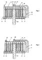
- double clutch has a clutch housing 2 which is rotatably connected via a Torsionsdämpferatti 3 to a coupling flange 4 with a drive shaft 5 of a motor, not shown here.
- the torque of the motor is transmitted via the drive shaft 5, the coupling flange 4 and the clutch housing 2 to a clutch housing cover 6 which is rotatably connected to a two-part clutch hub 7.
- the clutch hub 7 is rotatably supported about a fixed clutch shaft 8, which is fixedly connected to a housing 9 of a transmission, of which in the FIG. 1 nor a first transmission input shaft 10 and a second transmission input shaft 11 is shown.
- the second transmission input shaft 11 is formed as a hollow shaft which is arranged coaxially with the first transmission input shaft 10.
- the fixed clutch axle 8 has the task of distributing oil, which is supplied from the transmission, in the dual clutch 1.
- a plurality of annular oil passages 12 are formed in the coupling axis 8, of which the oil flows into a system of oil holes 13.
- the second transmission input shaft 11 is rotatably connected to an inner clutch pot 18 which is coaxially disposed in the outer clutch pot 14.
- An annular side wall 19 of the inner clutch pot 18 is enclosed by the first side wall portion 16 of the outer clutch pot 14.
- a round bottom 20 of the inner clutch pot 18 extends parallel to the bottom 15 of the outer clutch pot 14 in the radial direction.
- the respective side walls of the coupling cups 14, 18 thus extend from the respective trays in the same axial direction.
- the inner clutch pot 18 is integrally formed, while the outer clutch pot consists of two pieces, namely from the bottom with the molded thereon first side wall portion 16 on the one hand and the second side wall portion 17 on the other.
- the first friction clutch 21 includes a plurality of outer disks 23 and a plurality of inner disks 24.
- the outer disks 23 are by means of a plurality of grooves 25 in the second Side wall portion 17 and in the grooves 25 cross-projections 26 on the outer disk 23 rotatably connected to the outer clutch pot 14.
- a first outer disk carrier for the rotationally fixed receiving the outer disk 23 of the first friction clutch 21 is.
- the inner disks 24 are held by a coupling web 27, wherein the coupling web 27 produces a rotationally fixed connection between the inner disk 24 and the clutch hub 8 and thus the drive shaft 5. If the outer disks 23 and the inner disks 24 are compressed via an axially displaceable pressure plate 27, a torque is transmitted by the friction between inner disks 24 and outer disks 23. This results in a power flow between the drive shaft 5 and the first transmission input shaft.
- the pressure plate 28 is actuated by a cylinder-piston unit 29. A spring 30 pushes the pressure plate 28 back to its original position when the cylinder-piston unit 29 is not acted upon by a corresponding oil pressure.
- the second friction clutch 22 also has outer plates designated 23 and inner plates 24 designated 24, which, when compressed, establish a force flow between the drive shaft 5 and the second transmission input shaft 11.
- the outer disks 23 of the second friction clutch 22 are identical to the outer disks 23 of the first friction clutch 21. The same applies to the inner disks 24.
- the pressurization for actuating the second friction clutch 22 is similar to the pressurization of the first friction clutch 21.
- identical / similar components are used so that a certain symmetry in the construction of the double clutch 1 relative to the coupling web 27 can be seen. In the FIG. 1 Therefore, identical / similar components receive the same reference numerals.
- the side wall 19 of the inner clutch pot 18 is formed as a second outer disk carrier through which the outer disks 23 of the second friction clutch 22 are rotatably received.
- the second side wall part 17 has an inner diameter 31, which corresponds to an inner diameter 32 of the side wall 19 of the inner clutch pot 18. Therefore, the inner clutch pot 18 can not be taken out of the outer clutch pot 14, since the second side wall part 17 is fixedly connected via a weld 33 to the first side wall part 16 of the outer clutch pot is.
- the second side wall part 17 has, at an end facing the first side wall part 16, a radially outwardly directed section 34 which rests in parallel on a likewise radially outwardly directed section 35 of the first side wall part.
- the two sections 34, 35 form a common, circumferential surface on which the weld 33 is set.
- FIG. 2 shows a second embodiment, in which only the outer plates 23 and inner plates 24 of the first and second friction clutch 21, 22, the inner and outer clutch pot 14, 18 and the coupling web 27 are shown here in detail.
- the second side wall part 17 is modified.
- a radially outwardly directed portion 36 is provided directly on the pot edge, so that the side wall portion 17 in the ring profile is U-shaped and the sections 35, 36 can be considered as U-legs.
- an outer ring 37 may be provided, which, as in FIG. 3 to see, outside the second side wall portion 17 abuts and is welded thereto. This gives the outer clutch pot 14 a stiffness, so that even at high speeds, the outer disks 23 are held in the exact radial position.
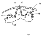
- FIG. 4 shows a further embodiment in which the first outer disk carrier is formed separately, so not integral with the side wall or with the side wall portion 17 of the outer clutch pot 14.
- the separately designed outer disk carrier is denoted by 38 and has a plurality of parallel grooves 39 into which the projections 26 of the outer disk 23, which projects radially outward, engage.
- At least three circumferentially distributed grooves 39a (in the FIG. 4 If only one groove 39a is shown) of the plurality of grooves 39 have an enlarged groove depth, so that in each case a groove bottom 40 bears against an outer coupling pot 41 and is connected to it by means of a weld seam 42.
Landscapes
- Engineering & Computer Science (AREA)
- General Engineering & Computer Science (AREA)
- Mechanical Engineering (AREA)
- Mechanical Operated Clutches (AREA)
- Hydraulic Clutches, Magnetic Clutches, Fluid Clutches, And Fluid Joints (AREA)
- Braking Arrangements (AREA)
Description
- Die Erfindung betrifft eine Doppelkupplung für ein Getriebe mit einer ersten Getriebeeingangswelle und einer dazu koaxial angeordneten zweiten Getriebeeingangswelle.
- Eine derartige Doppelkupplung ist aus der
EP 1 195 537 bekannt. Die Doppelkupplung umfasst dabei eine erste und zweite Reibkupplung, die in axialer Richtung der Doppelkupplung nebeneinander angeordnet sind und jeweils Außenlamellen und Innenlamellen aufweisen. Die Außenlamellen und die Innenlamellen einer Reibkupplung lassen sich durch eine hydraulische Kolben-Zylinder-Einheit zusammendrücken, so dass aufgrund der Reibung zwischen Außenlamellen und Innenlamellen ein Drehmoment übertragen wird. - Die Doppelkupplung aus der
EP 1 195 537 umfasst des weiteren ein Kupplungsgehäuse, das beispielsweise von einem Verbrennungsmotor in einem Kraftfahrzeug angetrieben werden kann. Das Kupplungsgehäuse ist drehfest mit den Innenlamellen der ersten und zweiten Reibkupplung verbunden. Die Innenlamellen der ersten Reibkupplung unterscheiden sich nicht von den Innenlamellen der zweiten Kupplung. - Ein äußerer Kupplungstopf verbindet die Außenlamellen der ersten Reibkupplung drehfest mit der ersten Getriebeeingangswelle, so dass bei zusammengedrücktem Lamellenpaket der ersten Reibkupplung ein Drehmoment zwischen dem angetriebenen Kupplungsgehäuse und der ersten Getriebeeingangswelle übertragen wird. Dabei werden die Außenlamellen drehfest von einem ersten Außenlamellenträger aufgenommen, der einstückig an dem äußeren Kupplungstopf angeformt ist. Die drehfeste Aufnahme der Außenlamellen durch den Außenlamellenträgers erfolgt über axial längs verlaufende Nuten an einer Innenseite des Außenlamellenträgers, in die radial nach außen stehende Vorsprünge der Außenlamellen greifen. Ein Außendurchmesser der Außenlamellen (ohne die Vorsprünge gerechnet) ist dabei etwas kleiner als ein Innendurchmesser des Außenlamellenträgers, sodass sich die Außenlamellen in axialer Richtung relativ zum Außenlamellenträger verschieben beziehungsweise in den äußeren Kupplungstopf hineinschieben lassen.
- In ähnlicher Weise wie der äußere Kupplungstopf weist ein innerer Kupplungstopf, der in dem äußeren Kupplungstopf angeordnet ist, ebenfalls am Topfrand einen einstückig angeformten zweiten Außenlamellenträger für die drehfeste Aufnahme der Außenlamellen der zweiten Reibkupplung auf. Auch hier ist ein Innendurchmesser des zweiten Außenlamellenträgers, der einem Innendurchmesser am Topfrand des inneren Kupplungstopfes entspricht, etwas größer als ein Außendurchmesser der betreffenden Außenlamellen, um Letztgenannte in den Kupplungstopf schieben zu können. Über Nuten und Vorsprünge wird wie bei der ersten Reibkupplung zwischen Außenlamellen und Kupplungstopf ein Formschluss in Umfangsrichtung hergestellt.
- Wie oben bereits erwähnt, liegt der innere Kupplungstopf in dem äußeren Kupplungstopf. Damit bei der Montage der Doppelkupplung der innere Kupplungstopf in den äußeren Kupplungstopf gelegt beziehungsweise bei der Demontage aus diesem herausgenommen werden kann, ist der Innendurchmesser am Topfrand des äußeren Kupplungstopfes größer als ein Außendurchmesser des inneren Kupplungstopfes. Dies bedingt, dass der Innendurchmesser des äußeren Kupplungstopfs größer ist als der Innendurchmesser des inneren Kupplungstopfs. Um diese Differenz auszugleichen, sind die Außenlamellen des äußeren Kupplungstopfes mit entsprechend größerem Außendurchmesser ausgebildet.
- Aufgrund der unterschiedlich großen Außenlamellen verhalten sich die beiden Kupplungen thermisch und mechanisch unterschiedlich. Dies kann zu Einbußen beim Fahrkomfort eines mit dieser Doppelkupplung bestückten Kraftfahrzeugs führen oder erfordert, um keine Einbußen beim Fahrkomfort hinnehmen zu müssen, ein aufwendiges Kupplungsmanagement.
- Aus der gattungsbildenden
WO 2004/104439 A1 ist eine Doppelkupplung mit einer ersten Reibkupplung und einer axial daneben angeordneten zweiten Reibkupplung bekannt, deren jeweilige Außenlamellenträger zur Aufnahme gleichgroßer Außenlamellen ausgebildet sind. Dies bedeutet, dass in der ersten und zweiten Reibkupplung gleichgroße Außenlamellen zur Anwendung kommen können. Durch die gleichgroßen Außenlamellen und durch gleichgroße Innenlamellen, so wie sie ebenfalls aus dem anderen, oben erwähnten Stand der Technik bekannt sind, zeigen die erste und die zweite Reibkupplung ein vergleichbares thermisches und mechanisches Verhalten. Dieses günstige Verhalten kann somit auch bei Doppelkupplungen mit zwei Kupplungstöpfen genutzt werden, bei denen einer der beiden Kupplungstöpfe in dem anderen Kupplungstopf (äußerer Kupplungstopf) liegt und das Drehmoment der ersten und zweiten Reibkupplung über jeweils eine gleiche axiale Seite zu den Getriebeeingangswellen abgeführt wird. Insbesondere bedeutet die Aufnahme baugleicher Außenlamellen, dass die Innendurchmesser des ersten und zweiten Außenlamellenträgers gleich sind. - Bei der in
WO 2004/104439 A1 offenbarten Doppelkupplung wird eine im wesentlichen zylindrische Seitenwand des äußeren Kupplungstopfes durch ein erstes, an einem Boden angrenzendes Seitenwandteil und durch ein zweites, vom Boden entferntes Seitenwandteil gebildet. Das erste Seitenwandteil erstreckt sich vom Boden ausgehend in axialer Richtung der Doppelkupplung und hat eine zylindrische Form. Dem ersten Seitenwandteil schließt sich in axialer Richtung das zweite Seitenwandteil an, wobei das zweite Seitenwandteil einen Außendurchmesser aufweist, der kleiner als ein Außendurchmesser des ersten Seitenwandteiles ist. In Einbaulage umschließt das erste, bodenangrenzende Seitenwandteil eine zylindrische Seitenwand des inneren Kupplungstopfes, während das zweite Seitenwandteil den Außenlamellenträger hält, der die Außenlamellen der ersten Reibkupplung aufnimmt. Somit wird das Drehmoment der ersten Kupplung auf das zweite Seitenwandteil geleitet, und wird über das erste Seitenwandteil und über den Boden des äußeren Kupplungstopfes zur ersten Getriebeeingangswelle geführt. Die Seitenwand und der Boden des äußeren Kupplungstopfes sind jeweils einstückig ausgebildet und sind mit einer Art Steckverbindung miteinander verbunden, durch die das Drehmoment von der Seitenwand auf den Boden geleitet wird. Jedoch ist eine Steckverbindung mit einem erhöhten Montageaufwand verbunden. Auch muss, um eine Unwucht der sich im Betrieb der Doppelkupplung rotierenden Seitenwand zu verhindern, eine genaue Positionierung der zylindrischen Seitenwand in radialer Richtung ebenfalls von der Steckverbindung geleistet werden, so dass diese aufwändig zu gestalten ist. - Der Erfindung liegt daher die Aufgabe zugrunde, eine Doppelkupplung der oben beschriebenen Art bereitzustellen, die einfach und kompakt aufgebaut ist, keine besonderen Anforderungen an das Kupplungsmanagement stellt, einen hohen Fahrkomfort ermöglicht und sich gut herstellen lässt.
- Die der Erfindung zu Grunde liegende Aufgabe wird mit den Merkmalskombinationen gemäß Anspruch 1 oder gemäß Anspruch 5 gelöst. Bevorzugte Ausführungsbeispiele können den Unteransprüchen entnommen werden
- Gemäß Anspruch 1 sind das erste und das zweite Seitenwandteil des äußeren Kupplungstopfes miteinander verschweißt. Ist bei einstückig ausgeführtem zweiten Seitenwandteil und Außenlamellenträger der Außendurchmesser des inneren Kupplungstopfes größer als der Innendurchmesser am Topfrand des äußeren Kupplungstopfes, muss vor dem Verschweißen der beiden Seitenwandteile der innere Kupplungstopf in den äußeren Kupplungstopf beziehungsweise in das erste Seitenwandteil des äußeren Kupplungstopfes gelegt werden. Nach dem Zusammenfügen, was auch durch andere geeignete Verfahren wie Löten möglich ist, lässt sich der innere Kupplungstopf dann nicht mehr aus dem äußeren Kupplungstopf herausnehmen.
- In einem Ausführungsbeispiel sind das zweite Seitenwandteil und der erste Außenlamellenträger einstückig ausgebildet, der erste Außenlamellenträger und das zweite, am Topfrand liegende Seitenwandteil sind ein Bauteil. An einer Innenseite des Seitenwandteils sind dabei die längsverlaufenden Nuten vorgesehen, die die radial nach außen stehenden Vorsprünge der Außenlamellen aufnehmen. Der Innendurchmesser des zweiten Seitenwandteils oder der Innendurchmesser am Topfrand des äußeren Kupplungstopfes entspricht somit dem Innendurchmesser des ersten Außenlamellenträgers. Der Innendurchmesser ist dabei der Durchmesser des Außenlamellenträgers, auf dem die Oberkanten der Nuten des Außenlamellenträgers liegen. Der Innendurchmesser des Außenlamellenträgers ist etwas größer als der Außendurchmesser der Außenlamellen, der die Basis für die nach radial nach außen ragenden Vorsprünge bildet.
- Das erste und das zweite Seitenwandteil können an jeweils einem zum anderen Seitenwandteil zugewandten Ende einen radial nach außen gerichteten Abschnitt aufweisen. Die Abschnitte der nebeneinander angeordneten Seitenwandteile liegen dann aneinander an und lassen sich beispielsweise an ihren radial nach außen stehenden Enden durch eine darauf gesetzte Schweißnaht verbinden. Die nach außen gerichteten Abschnitte sorgen für eine Versteifung der Seitenwandteile, so dass diese durch die im Betrieb der Doppelkupplung auftretenden Fliehkräfte weniger ausgeweitet werden.
- In einem bevorzugten Ausführungsbeispiel weist das zweite Seitenwandteil ein U-förmiges Ringprofil mit zwei Schenkeln auf, die radial nach außen zeigen. Die beiden Schenkel versteifen das zweite Seitenwandteil, wobei der dem ersten Seitenwandteil zugewandte Schenkel mit dem oben erwähnten Randabschnitt des ersten Seitenwandteiles verschweißt werden kann.
- Der erste Außenlamellenträger ist gemäß Anspruch 5 mit dem äußeren Kupplungstopf fest verbunden, nämlich verschweißt. Dabei kann der Außenlamellenträger zumindest an drei am Umfang verteilten Stellen an der Innenseite des äußeren Kupplungstopfes anliegen und dort verschweißt sein.
- Eine nicht durch die Erfindung gedeckte Möglichkeit besteht darin, dass der erste Außenlamellenträger mit dem äußeren Kupplungstopf lösbar verbunden ist. Dadurch kann bei Bedarf der innere Kupplungstopf aus dem äußeren Kupplungstopf genommen werden, wenn zuvor der Außenlamellenträger von dem äußeren Kupplungstopf demontiert worden ist.
- Vorzugsweise weisen der erste Außenlamellenträger und der zweite Außenlamellenträger an jeweils einer Innenwand axial verlaufende und in Umfangsrichtung beabstandete Nuten auf, in die jeweils radial nach außen gerichtete Vorsprünge der Außenlamellen der ersten beziehungsweise der zweiten Reibkupplung greifen, wobei die Nutform und Anordnung der Nuten des ersten Außenlamellenträgers der Nutform und Anordnung der Nuten des zweiten Außenlamellenträgers entsprechen. Durch die axial verlaufenden Nuten sind die Außenlamellen der ersten und zweiten Reibkupplung in Umfangsrichtung formschlüssig mit dem jeweiligen Außenlamellenträger und somit mit dem entsprechenden Kupplungstopf verbunden. In axialer Richtung hingegen lassen sich die Außenlamellen relativ zu dem äußeren oder inneren Kupplungstopf verschieben, wobei die Vorsprünge einer Außenlamellen entlang der Nuten des Lamellenträgers gleiten. Aufgrund der gleichen Nutform und Anordnung der Nuten ist es möglich, dass die Außenlamellen mit den entsprechenden radial nach außen ragenden Vorsprüngen entlang der Innenseite der Seitenwand des äußeren Kupplungstopfes bis zu dem inneren Kupplungstopf geschoben werden können. Somit ist es trotz baugleicher Außenlamellen möglich, die zweite Reibkupplung beziehungsweise den inneren Kupplungstopf mit Außenlamellen zu bestücken.
- In einem bevorzugten Ausführungsbeispiel ist ein Außenring vorgesehen, der den äußeren Kupplungstopf von außen umgreift.
- Alternativ zu den obigen Ausführungsbeispielen kann der Außenring auch direkt an dem äußeren Kupplungstopf anliegen und vorzugsweise mit diesem verschweißt sein. Damit wird die Steifigkeit des äußeren Kupplungstopfes in radialer Richtung erhöht. Vorzugsweise befindet sich der Außenring in der Nähe des Topfrandes.
- Um in Einbaulage des inneren und äußeren Kupplungstopfes die Außenlamellen in die Nuten des inneren Kupplungstopfes in einfacher Weise schieben zu können, ist vorzugsweise eine Positionierhilfe vorgesehen, die eine exakte Ausrichtung des äußeren Kupplungstopfes zum inneren Kupplungstopfes in Umfangsrichtung ermöglicht. Exakte Ausrichtung heißt hier, dass die beiden Kupplungstöpfe zueinander einen bestimmten Drehwinkel aufweisen. Bei gewissen Drehwinkeln fluchten die Nuten des äußeren Kupplungstopfes mit den Nuten des inneren Kupplungstopfes. Somit müssen die Außenlamellen für den inneren Kupplungstopf nicht, nachdem sie mit ihren Vorsprüngen die Nuten des äußeren Kupplungstopfes durchlaufen haben, um ihre Achse gedreht zu werden, sondern können ohne umständliche Drehung in die Nuten des inneren Kupplungstopfes geschoben werden.
- In einem bevorzugten Ausführungsbeispiel weist die Positionierhilfe zwei Bohrungen auf, von denen eine durch den äußeren Kupplungstopf und die andere durch den inneren Kupplungstopf greift und die bei exakter Ausrichtung in Umfangsrichtung zueinander fluchten. Die exakte Ausrichtung kann nun durch einen Stift oder dergleichen fixiert werden, der durch beide Bohrungen greift und ein relatives Verdrehen der beiden Kupplungstöpfe verhindert. Die Bohrungen können am jeweiligen Boden oder an der jeweiligen Seitenwand der Kupplungstöpfe vorgesehen sein.
- Anhand der in den Figuren dargestellten Ausführungsbeispielen wird die Erfindung näher erläutert. Es zeigen:
- Figur 1
- ein erstes Ausführungsbeispiel der Erfindung im Längsschnitt;
- Figur 2
- einen Ausschnitt eines zweiten Ausführungsbeispiels im Längsschnitt;
- Figur 3
- einen Ausschnitt eines dritten Ausführungsbeispiels der Erfindung im Längsschnitt;
- Figur 4
- einen Ausschnitt eines vierten Ausführungsbeispiels im Querschnitt;
- Die in
Figur 1 gezeigte und allgemein mit 1 bezeichnete Doppelkupplung weist ein Kupplungsgehäuse 2 auf, das über eine Torsionsdämpfereinheit 3 an einem Kupplungsflansch 4 drehfest mit einer Antriebswelle 5 eines hier nicht dargestellten Motors verbunden ist. - Das Drehmoment des Motors wird über die Antriebswelle 5, den Kupplungsflansch 4 und dem Kupplungsgehäuse 2 auf einen Kupplungsgehäusedeckel 6 übertragen, der drehfest mit einer zweigeteilten Kupplungsnabe 7 verbunden ist. Die Kupplungsnabe 7 ist drehbar um eine feststehende Kupplungsachse 8 gelagert, die fest mit einem Gehäuse 9 eines Getriebes verbunden ist, von dem in der
Figur 1 noch eine erste Getriebeeingangswelle 10 und eine zweite Getriebeeingangswelle 11 dargestellt ist. Die zweite Getriebeeingangswelle 11 ist als Hohlwelle ausgebildet, die koaxial zur ersten Getriebeeingangswelle 10 angeordnet ist. - Neben der Drehlagerung der Kupplungsnabe 7 kommt der feststehenden Kupplungsachse 8 die Aufgabe zu, Öl, das aus dem Getriebe zugeführt wird, in der Doppelkupplung 1 zu verteilen. Dazu sind in der Kupplungsachse 8 mehrere ringförmige Ölkanäle 12 ausgebildet, von denen das Öl in ein System von Ölbohrungen 13 strömt.
- Die erste Getriebeeingangswelle 10 ist drehfest mit einem äußeren Kupplungstopf 14 verbunden. Der Kupplungstopf 14 weist einen runden Boden 15 auf, der sich in radialer Richtung der Doppelkupplung 1 erstreckt. Der runde Boden 15 geht in ein erstes Seitenwandteil 16 über, das sich in axialer Richtung senkrecht zum Boden 15 erstreckt. Dem ersten Seitenwandteil 16 schließt sich in axialer Richtung ein zweites Seitenwandteil 17 an. Das erste und das zweite Seitenwandteil 16, 17 bilden die Seitenwand des äußeren Kupplungstopfes 14
- Die zweite Getriebeeingangswelle 11 ist drehfest mit einem inneren Kupplungstopf 18 verbunden, der in dem äußeren Kupplungstopf 14 koaxial angeordnet liegt. Eine ringförmige Seitenwand 19 des inneren Kupplungstopfes 18 wird von dem ersten Seitenwandteil 16 des äußeren Kupplungstopfes 14 umschlossen. Ein runder Boden 20 des inneren Kupplungstopfes 18 erstreckt sich parallel zum Boden 15 des äußeren Kupplungstopfes 14 in radialer Richtung. Die jeweiligen Seitenwände der Kupplungstöpfe 14, 18 erstrecken sich damit von den jeweiligen Böden in gleicher axialer Richtung. Der innere Kupplungstopf 18 ist einstückig ausgebildet, während der äußere Kupplungstopf aus zwei Stücken besteht, nämlich aus dem Boden mit dem daran angeformten ersten Seitenwandteil 16 einerseits und dem zweiten Seitenwandteil 17 anderseits.
- Der Drehmomentübertragung zwischen den Getriebeeingangswellen 10, 11 und dem angetriebenen Kupplungsgehäuse 2 erfolgt über eine erste Reibkupplung 21 beziehungsweise über eine zweite Reibkupplung 22. Die erste Reibkupplung 21 umfasst mehrere Außenlamellen 23 und mehrere Innenlamellen 24. Die Außenlamellen 23 sind mittels mehrerer Nuten 25 in dem zweiten Seitenwandteil 17 und in die Nuten 25 greifender Vorsprünge 26 an den Außenlamellen 23 drehfest mit dem äußeren Kupplungstopf 14 verbunden. In diesem Ausführungsbeispiel stellt somit das zweite Seitenwandteil einen ersten Außenlamellenträger für die drehfeste Aufnahme der Außenlamellen 23 der ersten Reibkupplung 21 dar.
- Die Innenlamellen 24 werden von einem Kupplungssteg 27 gehalten, wobei der Kupplungssteg 27 eine drehfeste Verbindung zwischen den Innenlamellen 24 und der Kupplungsnabe 8 und damit der Antriebswelle 5 herstellt. Werden die Außenlamellen 23 und die Innenlamellen 24 über eine axial verschiebbare Druckplatte 27 zusammengedrückt, wird durch die Reibung zwischen Innenlamellen 24 und Außenlamellen 23 ein Drehmoment übertragen. Somit entsteht eine Kraftfluss zwischen der Antriebswelle 5 und der ersten Getriebeeingangswelle. Die Druckplatte 28 wird durch eine Zylinder-Kolbeneinheit 29 betätigt. Eine Feder 30 drückt die Druckplatte 28 wieder in ihre Ausgangslage, wenn die Zylinder-Kolbeneinheit 29 nicht mit einem entsprechenden Öldruck beaufschlagt ist.
- Die zweite Reibkupplung 22 weist ebenfalls mit 23 bezeichnete Außenlamellen und mit 24 bezeichnete Innenlamellen 24 auf, die, wenn sie zusammengedrückt werden, einen Kraftfluss zwischen der Antriebswelle 5 und der zweiten Getriebeeingangswelle 11 herstellen. Die Außenlamellen 23 der zweiten Reibkupplung 22 sind baugleich zu den Außenlamellen 23 der ersten Reibkupplung 21. Gleiches gilt für die Innenlamellen 24. Die Druckbeaufschlagung zur Betätigung der zweiten Reibkupplung 22 ähnelt der Druckbeaufschlagung der ersten Reibkupplung 21. Dazu werden auch gleiche/gleichartige Bauteile verwendet, so dass eine gewisse Symmetrie im Aufbau der Doppelkupplung 1 bezogen auf den Kupplungssteg 27 zu erkennen ist. In der
Figur 1 erhalten gleiche/gleichartige Bauteile daher gleiche Bezugszeichen. Die Seitenwand 19 des inneren Kupplungstopfes 18 ist als ein zweiter Außenlamellenträger ausgebildet, durch den die Außenlamellen 23 der zweiten Reibkupplung 22 drehfest aufgenommen werden. - Das zweite Seitenwandteil 17 weist einen Innendurchmesser 31 auf, der einem Innendurchmesser 32 der Seitenwand 19 des inneren Kupplungstopfes 18 entspricht. Daher kann der innere Kupplungstopf 18 nicht aus dem äußeren Kupplungstopf 14 herausgenommen werden, da das zweite Seitenwandteil 17 über eine Schweißnaht 33 mit dem ersten Seitenwandteil 16 des äußeren Kupplungstopfes fest verbunden ist. Das zweite Seitenwandteil 17 weist an einem dem ersten Seitenwandteil 16 zugewandten Ende einen radial nach außen gerichteten Abschnitt 34 auf, der parallel an einem ebenfalls radial nach außen gerichteten Abschnitt 35 des ersten Seitenwandteiles anliegt. Die beiden Abschnitte 34, 35 bilden eine gemeinsame, umlaufende Fläche, auf die die Schweißnaht 33 gesetzt ist.
- Die
Figur 2 zeigt ein zweites Ausführungsbeispiel, wobei hier nur im Ausschnitt die Außenlamellen 23 und Innenlamellen 24 der ersten und zweiten Reibkupplung 21, 22, der innere und äußere Kupplungstopf 14, 18 sowie der Kupplungssteg 27 dargestellt sind. Gegenüber dem Ausführungsbeispiel derFigur 1 ist das zweite Seitenwandteil 17 modifiziert. Zur Verstärkung/Versteifung des äußeren Kupplungstopfes 14 ist direkt am Topfrand ein radial nach außen gerichteter Abschnitt 36 vorgesehen, so dass das Seitenwandteil 17 im Ringprofil U-förmig ist und die Abschnitte 35, 36 als U-Schenkel aufgefasst werden können. - Alternativ oder auch zusätzlich zur Verstärkung des äußeren Kupplungstopfes kann ein Außenring 37 vorgesehen sein, der, wie in
Figur 3 zu sehen, außen an dem zweiten Seitenwandteil 17 anliegt und mit diesem verschweißt ist. Dies gibt dem äußeren Kupplungstopf 14 eine Steifheit, so dass auch bei hohen Drehzahlen die Außenlamellen 23 in exakter radialer Position gehalten werden. -
Figur 4 zeigt ein weiteres Ausführungsbeispiel, bei dem der erste Außenlamellenträger separat, also nicht einstückig mit der Seitenwand oder mit dem Seitenwandteil 17 des äußeren Kupplungstopfes 14 ausgebildet ist. Der separat ausgeführte Außenlamellenträger wird mit 38 bezeichnet und weist eine Vielzahl parallel verlaufender Nuten 39 auf, in die die radial nach außen stehenden Vorsprünge 26 der Außenlamelle 23 greifen. Wenigstens drei am Umfang verteilte Nuten 39a (in derFigur 4 ist nur eine Nut 39a dargestellt) aus der Vielzahl der Nuten 39 weisen eine vergrößerte Nuttiefe auf, so dass jeweils ein Nutboden 40 an einem äußeren Kupplungstopf 41 anliegt und mittels einer Schweißnaht 42 mit diesem verbunden ist. -
- 1
- Doppelkupplung
- 2
- Kupplungsgehäuse
- 3
- Torsionsdämpfereinheit
- 4
- Kupplungsflansch
- 5
- Antriebswelle
- 6
- Kupplungsgehäusedeckel
- 7
- Kupplungsnabe
- 8
- Kupplungsachse
- 9
- Getriebegehäuse
- 10
- Erste Getriebeeingangswelle
- 11
- Zweite Getriebeeingangswelle
- 12
- Ölkanal
- 13
- Ölbohrung
- 14
- Äußerer Kupplungstopf
- 15
- Boden
- 16
- Seitenwandteil
- 17
- Seitenwandteil
- 18
- Innerer Kupplungstopf
- 19
- Seitenwand
- 20
- Boden
- 21
- Erste Reibkupplung
- 22
- Zweite Reibkupplung
- 23
- Außenlamelle
- 24
- Innenlamelle
- 25
- Nut
- 26
- Vorsprung
- 27
- Kupplungssteg
- 28
- Druckplatte
- 29
- Zylinder-Kolbeneinheit
- 30
- Feder
- 31
- Innendurchmesser
- 32
- Innendurchmesser
- 33
- Schweißnaht
- 34
- Abschnitt
- 35
- Abschnitt
- 36
- Abschnitt
- 37
- Außenring
- 38
- Außenlamellenträger
- 39
- Nut (39a)
- 40
- Nutboden
- 41
- Äußerer Kupplungstopf
- 42
- Schweißnaht
Claims (10)
- Doppelkupplung (1) für ein Getriebe mit einer ersten Getriebeeingangswelle (10) und einer dazu koaxial angeordneten zweiten Getriebeeingangswelle (11), umfassend- eine erste Reibkupplung (21) und zweite Reibkupplung (22), die in axialer Richtung nebeneinander angeordnet sind und jeweils ein Lamellenpaket mit Außenlamellen (23) und Innenlamellen (24) aufweisen,- ein antreibbares Bauteil (2), das drehfest mit den Innenlamellen (24) der ersten und zweiten Reibkupplung (21, 22) verbunden ist;- einen ersten Außenlamellenträger (17; 38) für die drehfeste Aufnahme der Außenlamellen der ersten Reibkupplung (21) und einen zweiten Außenlamellenträger (19) für die drehfeste Aufnahme der Außenlamellen (23) der zweiten Reibkupplung (22), wobei der erste Außenlamellenträger (17; 38) und der zweite Außenlamellenträger (19) zur Aufnahme baugleicher Außenlamellen (23) ausgebildet sind;- einen äußeren Kupplungstopf (14; 41), der den ersten Außenlamellenträger (17; 38) drehfest mit der ersten Getriebeeingangswelle (10) verbindet, und einen in dem äußeren Kupplungstopf (14) liegenden, inneren Kupplungstopf (18), der den zweiten Außenlamellenträger (19) drehfest mit der zweiten Getriebeeingangswelle (11) verbindet, wobei eine Seitenwand des äußeren Kupplungstopfes (14) ein erstes Seitenwandteil (16), das an einem Boden des äußeren Kupplungstopfes (14) angrenzt, und ein zweites Seitenwandteil (17) aufweist, das sich dem ersten Seitenwandteil (16) in axialer Richtung anschließt, wobei das zweite Seitenwandteil (17) einen Außendurchmesser aufweist, der kleiner als ein Außendurchmesser des ersten Seitenwandteiles (16) istdadurch gekennzeichnet, dass das erste und das zweite Seitenwandteil (16, 17) des äußeren Kupplungstopfes (14) miteinander verschweißt sind.
- Doppelkupplung (1) nach Anspruch 1, dadurch gekennzeichnet, dass das zweite Seitenwandteil (17) und der erste Außenlamellenträger (17) einstückig ausgebildet sind.
- Doppelkupplung (1) nach Anspruch 1 oder 2, dadurch gekennzeichnet, dass das erste Seitenwandteil (16) und das zweite Seitenwandteil (17) jeweils an einem zum anderen Seitenwandteil zugewandten Ende einen radial nach außen gerichteten Abschnitt (34, 35) aufweisen.
- Doppelkupplung (1) nach einem der Ansprüche 1 bis 3, dadurch gekennzeichnet, dass das zweite Seitenwandteil (17) ein U-förmiges Ringprofil mit zwei Schenkeln aufweist, die radial nach außen gerichtet sind.
- Doppelkupplung (1) für ein Getriebe mit einer ersten Getriebeeingangswelle (10) und einer dazu koaxial angeordneten zweiten Getriebeeingangswelle (11), umfassend- eine erste Reibkupplung (21) und zweite Reibkupplung (22), die in axialer Richtung nebeneinander angeordnet sind und jeweils ein Lamellenpaket mit Außenlamellen (23) und Innenlamellen (24) aufweisen,- ein antreibbares Bauteil (2), das drehfest mit den Innenlamellen (24) der ersten und zweiten Reibkupplung (21, 22) verbunden ist;- einen ersten Außenlamellenträger (17; 38) für die drehfeste Aufnahme der Außenlamellen der ersten Reibkupplung (21) und einen zweiten Außenlamellenträger (19) für die drehfeste Aufnahme der Außenlamellen (23) der zweiten Reibkupplung (22), wobei der erste Außenlamellenträger (17; 38) und der zweite Außenlamellenträger (19) zur Aufnahme baugleicher Außenlamellen (23) ausgebildet sind;- einen äußeren Kupplungstopf (14; 41), der den ersten Außenlamellenträger (17; 38) drehfest mit der ersten Getriebeeingangswelle (10) verbindet, und einen in dem äußeren Kupplungstopf (14) liegenden, inneren Kupplungstopf (18), der den zweiten Außenlamellenträger (19) drehfest mit der zweiten Getriebeeingangswelle (11) verbindet,dadurch gekennzeichnet, dass der erste Außenlamellenträger (38) mit dem äußeren Kupplungstopfes (41) verschweißt ist.
- Doppelkupplung (1) nach einem der Ansprüche 1 bis 5, dadurch gekennzeichnet, dass der erste Außenlamellenträger (17; 38) und der zweite Außenlamellenträger (19) jeweils an einer Innenseite axial verlaufende und in Umfangsrichtung beabstandete Nuten (25; 39, 39a) aufweisen, in die jeweils radial nach außen gerichtete Vorsprünge (26) der Außenlamellen (23) der ersten beziehungsweise zweiten Reibkupplung (21, 22) greifen, wobei die Nutform und Anordnung der Nuten des ersten Außenlamellenträges der Nutform und Anordnung der Nuten des zweiten Außenlamellenträgers entsprechen.
- Doppelkupplung (1) nach einem der Ansprüche 1 bis 6, dadurch gekennzeichnet, dass ein Außenring (37) den äußeren Kupplungstopf (14) von außen umgreift.
- Doppelkupplung (1) nach Anspruch 7, dadurch gekennzeichnet, dass der Außenring (37) außen an dem äußeren Kupplungstopf (14) anliegt und vorzugsweise mit diesem verschweißt ist.
- Doppelkupplung (1) nach einem der Ansprüche 1 bis 8, dadurch gekennzeichnet, dass eine Positionierhilfe vorgesehen ist, die eine exakte Festlegung eines Drehwinkels zwischen dem äußeren Kupplungstopf (14; 41) und dem inneren Kupplungstopf (18) ermöglicht.
- Doppelkupplung (1) nach Anspruch 9, dadurch gekennzeichnet, dass die Positionierhilfe zwei Bohrungen aufweist, von denen eine durch den äußeren Kupplungstopf (14) und die andere durch den inneren Kupplungstopf (18) greift und die bei einem bestimmten Drehwinkel zwischen den Kupplungstöpfen (14, 18) zueinander fluchten.
Priority Applications (3)
| Application Number | Priority Date | Filing Date | Title |
|---|---|---|---|
| EP05100531A EP1686277B1 (de) | 2005-01-27 | 2005-01-27 | Doppelkupplung mit gleichgrossen Lamellen |
| DE502005007777T DE502005007777D1 (de) | 2005-01-27 | 2005-01-27 | Doppelkupplung mit gleichgrossen Lamellen |
| AT05100531T ATE438044T1 (de) | 2005-01-27 | 2005-01-27 | Doppelkupplung mit gleichgrossen lamellen |
Applications Claiming Priority (1)
| Application Number | Priority Date | Filing Date | Title |
|---|---|---|---|
| EP05100531A EP1686277B1 (de) | 2005-01-27 | 2005-01-27 | Doppelkupplung mit gleichgrossen Lamellen |
Publications (2)
| Publication Number | Publication Date |
|---|---|
| EP1686277A1 EP1686277A1 (de) | 2006-08-02 |
| EP1686277B1 true EP1686277B1 (de) | 2009-07-29 |
Family
ID=34938586
Family Applications (1)
| Application Number | Title | Priority Date | Filing Date |
|---|---|---|---|
| EP05100531A Expired - Lifetime EP1686277B1 (de) | 2005-01-27 | 2005-01-27 | Doppelkupplung mit gleichgrossen Lamellen |
Country Status (3)
| Country | Link |
|---|---|
| EP (1) | EP1686277B1 (de) |
| AT (1) | ATE438044T1 (de) |
| DE (1) | DE502005007777D1 (de) |
Cited By (1)
| Publication number | Priority date | Publication date | Assignee | Title |
|---|---|---|---|---|
| EP4707631A1 (de) * | 2024-09-09 | 2026-03-11 | Transmisiones Y Equipos Mecánicos, S.A. de C.V. | Kompakte parallel-doppelkupplungseinheit |
Families Citing this family (8)
| Publication number | Priority date | Publication date | Assignee | Title |
|---|---|---|---|---|
| EP1783388B1 (de) * | 2005-11-04 | 2014-07-02 | Schaeffler Technologies GmbH & Co. KG | Lamellenkupplungseinrichtung |
| DE102008045791B4 (de) * | 2007-11-11 | 2020-08-06 | Saic Motor Corp. Ltd. | Doppelkupplungsgetriebe und Verfahren zur Montage eines Doppelkupplungsgetriebes |
| DE102010046633B4 (de) * | 2010-09-20 | 2012-10-18 | Gkn Stromag Ag | Doppelschaltkupplung |
| DE102012222915B4 (de) | 2012-12-12 | 2014-12-31 | Gkn Stromag Ag | Doppelschaltkupplung mit zwei kraftschlüssig wirksamen Kupplungseinheiten |
| FR3026152B1 (fr) * | 2014-09-18 | 2018-03-02 | Valeo Embrayages | Mecanisme a double embrayage humide pour un systeme de transmission |
| FR3027077B1 (fr) | 2014-10-09 | 2018-01-26 | Valeo Embrayages | Systeme de transmission comportant un mecanisme a double embrayage humide |
| CN105840682B (zh) * | 2015-01-29 | 2020-12-15 | 舍弗勒技术股份两合公司 | 离合器装置 |
| US10851844B2 (en) * | 2016-11-16 | 2020-12-01 | E-Aam Driveline Systems Ab | Clutch assembly |
Family Cites Families (4)
| Publication number | Priority date | Publication date | Assignee | Title |
|---|---|---|---|---|
| FR1469727A (fr) * | 1966-02-21 | 1967-02-17 | Bosch Gmbh Robert | Boîte de vitesses à carter stationnaire |
| DE9114528U1 (de) * | 1991-11-22 | 1992-02-13 | Zahnradfabrik Friedrichshafen Ag, 7990 Friedrichshafen | Doppelkupplung |
| DE50001452D1 (de) | 2000-10-05 | 2003-04-17 | Ford Global Tech Inc | Doppelkupplung für ein Getriebe mit zwei Getriebeeingangswellen |
| DE10323514A1 (de) | 2003-05-24 | 2004-12-23 | Dr.Ing.H.C. F. Porsche Ag | Kupplungsvorrichtung, insbesondere Lamellenkupplung für ein Doppelkupplungsgetriebe |
-
2005
- 2005-01-27 AT AT05100531T patent/ATE438044T1/de not_active IP Right Cessation
- 2005-01-27 DE DE502005007777T patent/DE502005007777D1/de not_active Expired - Lifetime
- 2005-01-27 EP EP05100531A patent/EP1686277B1/de not_active Expired - Lifetime
Cited By (1)
| Publication number | Priority date | Publication date | Assignee | Title |
|---|---|---|---|---|
| EP4707631A1 (de) * | 2024-09-09 | 2026-03-11 | Transmisiones Y Equipos Mecánicos, S.A. de C.V. | Kompakte parallel-doppelkupplungseinheit |
Also Published As
| Publication number | Publication date |
|---|---|
| ATE438044T1 (de) | 2009-08-15 |
| EP1686277A1 (de) | 2006-08-02 |
| DE502005007777D1 (de) | 2009-09-10 |
Similar Documents
| Publication | Publication Date | Title |
|---|---|---|
| DE102014209618B4 (de) | Mehrfachkupplungseinrichtung | |
| DE69633412T2 (de) | Riemenscheibe | |
| DE10319415A1 (de) | Hydrodynamischer Momentwandler, insbesondere für Kraftfahrzeuge | |
| EP1515059A1 (de) | Einrichtung zur axialen Sicherung einer Kupplungseinrichtung an einer Drehdurchführung | |
| DE102018211377B4 (de) | Rotorträger für eine elektrische Maschine | |
| DE102015213874A1 (de) | Axiale Lamellenkupplung | |
| DE102012204815A1 (de) | Kupplungsanordnung | |
| DE102013216333A1 (de) | Mehrfachkupplungsvorrichtung, insbesondere Doppelkupplungsvorrichtung | |
| DE102007058417B4 (de) | Turbinen- und pumpenräder für drehmomentwandler | |
| EP1726842B1 (de) | Kupplungsanordnung in radial geschachtelter Bauart | |
| EP1686276B1 (de) | Doppelkupplung mit Kupplungssteg | |
| DE3823743C2 (de) | Schwingungsdämpfer-Schwungscheibe | |
| EP1614919B1 (de) | Kupplungsanordnung | |
| DE102011086712A1 (de) | Drehmomentübertragungseinrichtung | |
| DE102014225967A1 (de) | Antriebssteg für eine axiale Doppelkupplung | |
| EP1686277A1 (de) | Doppelkupplung mit gleichgrossen Lamellen | |
| DE102015213873B4 (de) | Axiale Lamellenkupplung | |
| DE4201370C1 (en) | Resilient spring drive for ic engine - connects drive input and output members using coil springs separated by spacers on curved rod | |
| DE102015222191A1 (de) | Nasslaufende Doppelkupplung | |
| DE102015225034A1 (de) | Lamellenträgerverbindung | |
| WO2019206358A1 (de) | Kupplungsanordnung mit als blechteil ausgebildeten und mit einem rotorträger verbundenen tragbestandteil; sowie antriebsstrang | |
| DE102015207825A1 (de) | Drehschwingungsdämpfungsanordnung für den Antriebsstrang eines Fahrzeugs | |
| DE3715369A1 (de) | Kupplungsvorrichtung | |
| DE102011084847A1 (de) | Drehmomentübertragungseinrichtung | |
| DE102016222892B4 (de) | Drehmomentübertragungseinrichtung |
Legal Events
| Date | Code | Title | Description |
|---|---|---|---|
| PUAI | Public reference made under article 153(3) epc to a published international application that has entered the european phase |
Free format text: ORIGINAL CODE: 0009012 |
|
| AK | Designated contracting states |
Kind code of ref document: A1 Designated state(s): AT BE BG CH CY CZ DE DK EE ES FI FR GB GR HU IE IS IT LI LT LU MC NL PL PT RO SE SI SK TR |
|
| AX | Request for extension of the european patent |
Extension state: AL BA HR LV MK YU |
|
| 17P | Request for examination filed |
Effective date: 20070202 |
|
| AKX | Designation fees paid |
Designated state(s): AT BE BG CH CY CZ DE DK EE ES FI FR GB GR HU IE IS IT LI LT LU MC NL PL PT RO SE SI SK TR |
|
| 17Q | First examination report despatched |
Effective date: 20070926 |
|
| GRAP | Despatch of communication of intention to grant a patent |
Free format text: ORIGINAL CODE: EPIDOSNIGR1 |
|
| GRAS | Grant fee paid |
Free format text: ORIGINAL CODE: EPIDOSNIGR3 |
|
| GRAA | (expected) grant |
Free format text: ORIGINAL CODE: 0009210 |
|
| AK | Designated contracting states |
Kind code of ref document: B1 Designated state(s): AT BE BG CH CY CZ DE DK EE ES FI FR GB GR HU IE IS IT LI LT LU MC NL PL PT RO SE SI SK TR |
|
| REG | Reference to a national code |
Ref country code: GB Ref legal event code: FG4D Free format text: NOT ENGLISH |
|
| REG | Reference to a national code |
Ref country code: CH Ref legal event code: EP |
|
| REG | Reference to a national code |
Ref country code: IE Ref legal event code: FG4D |
|
| REF | Corresponds to: |
Ref document number: 502005007777 Country of ref document: DE Date of ref document: 20090910 Kind code of ref document: P |
|
| NLV1 | Nl: lapsed or annulled due to failure to fulfill the requirements of art. 29p and 29m of the patents act | ||
| PG25 | Lapsed in a contracting state [announced via postgrant information from national office to epo] |
Ref country code: IS Free format text: LAPSE BECAUSE OF FAILURE TO SUBMIT A TRANSLATION OF THE DESCRIPTION OR TO PAY THE FEE WITHIN THE PRESCRIBED TIME-LIMIT Effective date: 20091129 Ref country code: SE Free format text: LAPSE BECAUSE OF FAILURE TO SUBMIT A TRANSLATION OF THE DESCRIPTION OR TO PAY THE FEE WITHIN THE PRESCRIBED TIME-LIMIT Effective date: 20090729 Ref country code: LT Free format text: LAPSE BECAUSE OF FAILURE TO SUBMIT A TRANSLATION OF THE DESCRIPTION OR TO PAY THE FEE WITHIN THE PRESCRIBED TIME-LIMIT Effective date: 20090729 Ref country code: FI Free format text: LAPSE BECAUSE OF FAILURE TO SUBMIT A TRANSLATION OF THE DESCRIPTION OR TO PAY THE FEE WITHIN THE PRESCRIBED TIME-LIMIT Effective date: 20090729 Ref country code: ES Free format text: LAPSE BECAUSE OF FAILURE TO SUBMIT A TRANSLATION OF THE DESCRIPTION OR TO PAY THE FEE WITHIN THE PRESCRIBED TIME-LIMIT Effective date: 20091109 |
|
| PG25 | Lapsed in a contracting state [announced via postgrant information from national office to epo] |
Ref country code: PL Free format text: LAPSE BECAUSE OF FAILURE TO SUBMIT A TRANSLATION OF THE DESCRIPTION OR TO PAY THE FEE WITHIN THE PRESCRIBED TIME-LIMIT Effective date: 20090729 Ref country code: SI Free format text: LAPSE BECAUSE OF FAILURE TO SUBMIT A TRANSLATION OF THE DESCRIPTION OR TO PAY THE FEE WITHIN THE PRESCRIBED TIME-LIMIT Effective date: 20090729 Ref country code: NL Free format text: LAPSE BECAUSE OF FAILURE TO SUBMIT A TRANSLATION OF THE DESCRIPTION OR TO PAY THE FEE WITHIN THE PRESCRIBED TIME-LIMIT Effective date: 20090729 |
|
| REG | Reference to a national code |
Ref country code: IE Ref legal event code: FD4D |
|
| PG25 | Lapsed in a contracting state [announced via postgrant information from national office to epo] |
Ref country code: PT Free format text: LAPSE BECAUSE OF FAILURE TO SUBMIT A TRANSLATION OF THE DESCRIPTION OR TO PAY THE FEE WITHIN THE PRESCRIBED TIME-LIMIT Effective date: 20091129 Ref country code: BG Free format text: LAPSE BECAUSE OF FAILURE TO SUBMIT A TRANSLATION OF THE DESCRIPTION OR TO PAY THE FEE WITHIN THE PRESCRIBED TIME-LIMIT Effective date: 20091029 |
|
| PG25 | Lapsed in a contracting state [announced via postgrant information from national office to epo] |
Ref country code: EE Free format text: LAPSE BECAUSE OF FAILURE TO SUBMIT A TRANSLATION OF THE DESCRIPTION OR TO PAY THE FEE WITHIN THE PRESCRIBED TIME-LIMIT Effective date: 20090729 Ref country code: RO Free format text: LAPSE BECAUSE OF FAILURE TO SUBMIT A TRANSLATION OF THE DESCRIPTION OR TO PAY THE FEE WITHIN THE PRESCRIBED TIME-LIMIT Effective date: 20090729 Ref country code: IE Free format text: LAPSE BECAUSE OF FAILURE TO SUBMIT A TRANSLATION OF THE DESCRIPTION OR TO PAY THE FEE WITHIN THE PRESCRIBED TIME-LIMIT Effective date: 20090729 Ref country code: DK Free format text: LAPSE BECAUSE OF FAILURE TO SUBMIT A TRANSLATION OF THE DESCRIPTION OR TO PAY THE FEE WITHIN THE PRESCRIBED TIME-LIMIT Effective date: 20090729 Ref country code: CZ Free format text: LAPSE BECAUSE OF FAILURE TO SUBMIT A TRANSLATION OF THE DESCRIPTION OR TO PAY THE FEE WITHIN THE PRESCRIBED TIME-LIMIT Effective date: 20090729 |
|
| PG25 | Lapsed in a contracting state [announced via postgrant information from national office to epo] |
Ref country code: SK Free format text: LAPSE BECAUSE OF FAILURE TO SUBMIT A TRANSLATION OF THE DESCRIPTION OR TO PAY THE FEE WITHIN THE PRESCRIBED TIME-LIMIT Effective date: 20090729 |
|
| PLBE | No opposition filed within time limit |
Free format text: ORIGINAL CODE: 0009261 |
|
| STAA | Information on the status of an ep patent application or granted ep patent |
Free format text: STATUS: NO OPPOSITION FILED WITHIN TIME LIMIT |
|
| 26N | No opposition filed |
Effective date: 20100503 |
|
| BERE | Be: lapsed |
Owner name: GETRAG FORD TRANSMISSIONS G.M.B.H. Effective date: 20100131 |
|
| PG25 | Lapsed in a contracting state [announced via postgrant information from national office to epo] |
Ref country code: MC Free format text: LAPSE BECAUSE OF NON-PAYMENT OF DUE FEES Effective date: 20100131 |
|
| REG | Reference to a national code |
Ref country code: CH Ref legal event code: PL |
|
| PG25 | Lapsed in a contracting state [announced via postgrant information from national office to epo] |
Ref country code: CH Free format text: LAPSE BECAUSE OF NON-PAYMENT OF DUE FEES Effective date: 20100131 Ref country code: LI Free format text: LAPSE BECAUSE OF NON-PAYMENT OF DUE FEES Effective date: 20100131 Ref country code: GR Free format text: LAPSE BECAUSE OF FAILURE TO SUBMIT A TRANSLATION OF THE DESCRIPTION OR TO PAY THE FEE WITHIN THE PRESCRIBED TIME-LIMIT Effective date: 20091030 |
|
| PG25 | Lapsed in a contracting state [announced via postgrant information from national office to epo] |
Ref country code: BE Free format text: LAPSE BECAUSE OF NON-PAYMENT OF DUE FEES Effective date: 20100131 |
|
| PG25 | Lapsed in a contracting state [announced via postgrant information from national office to epo] |
Ref country code: IT Free format text: LAPSE BECAUSE OF FAILURE TO SUBMIT A TRANSLATION OF THE DESCRIPTION OR TO PAY THE FEE WITHIN THE PRESCRIBED TIME-LIMIT Effective date: 20090729 |
|
| PG25 | Lapsed in a contracting state [announced via postgrant information from national office to epo] |
Ref country code: AT Free format text: LAPSE BECAUSE OF NON-PAYMENT OF DUE FEES Effective date: 20100127 |
|
| PG25 | Lapsed in a contracting state [announced via postgrant information from national office to epo] |
Ref country code: CY Free format text: LAPSE BECAUSE OF FAILURE TO SUBMIT A TRANSLATION OF THE DESCRIPTION OR TO PAY THE FEE WITHIN THE PRESCRIBED TIME-LIMIT Effective date: 20090729 |
|
| PG25 | Lapsed in a contracting state [announced via postgrant information from national office to epo] |
Ref country code: LU Free format text: LAPSE BECAUSE OF NON-PAYMENT OF DUE FEES Effective date: 20100127 Ref country code: HU Free format text: LAPSE BECAUSE OF FAILURE TO SUBMIT A TRANSLATION OF THE DESCRIPTION OR TO PAY THE FEE WITHIN THE PRESCRIBED TIME-LIMIT Effective date: 20100130 |
|
| PG25 | Lapsed in a contracting state [announced via postgrant information from national office to epo] |
Ref country code: TR Free format text: LAPSE BECAUSE OF FAILURE TO SUBMIT A TRANSLATION OF THE DESCRIPTION OR TO PAY THE FEE WITHIN THE PRESCRIBED TIME-LIMIT Effective date: 20090729 |
|
| REG | Reference to a national code |
Ref country code: FR Ref legal event code: PLFP Year of fee payment: 12 |
|
| REG | Reference to a national code |
Ref country code: FR Ref legal event code: PLFP Year of fee payment: 13 |
|
| REG | Reference to a national code |
Ref country code: FR Ref legal event code: PLFP Year of fee payment: 14 |
|
| PGFP | Annual fee paid to national office [announced via postgrant information from national office to epo] |
Ref country code: GB Payment date: 20201231 Year of fee payment: 17 Ref country code: FR Payment date: 20201223 Year of fee payment: 17 |
|
| PGFP | Annual fee paid to national office [announced via postgrant information from national office to epo] |
Ref country code: DE Payment date: 20201218 Year of fee payment: 17 |
|
| REG | Reference to a national code |
Ref country code: DE Ref legal event code: R119 Ref document number: 502005007777 Country of ref document: DE |
|
| GBPC | Gb: european patent ceased through non-payment of renewal fee |
Effective date: 20220127 |
|
| PG25 | Lapsed in a contracting state [announced via postgrant information from national office to epo] |
Ref country code: GB Free format text: LAPSE BECAUSE OF NON-PAYMENT OF DUE FEES Effective date: 20220127 Ref country code: DE Free format text: LAPSE BECAUSE OF NON-PAYMENT OF DUE FEES Effective date: 20220802 |
|
| PG25 | Lapsed in a contracting state [announced via postgrant information from national office to epo] |
Ref country code: FR Free format text: LAPSE BECAUSE OF NON-PAYMENT OF DUE FEES Effective date: 20220131 |