EP1685758B1 - Kopplungsmechanismus und Mäher - Google Patents
Kopplungsmechanismus und Mäher Download PDFInfo
- Publication number
- EP1685758B1 EP1685758B1 EP05112443A EP05112443A EP1685758B1 EP 1685758 B1 EP1685758 B1 EP 1685758B1 EP 05112443 A EP05112443 A EP 05112443A EP 05112443 A EP05112443 A EP 05112443A EP 1685758 B1 EP1685758 B1 EP 1685758B1
- Authority
- EP
- European Patent Office
- Prior art keywords
- cutting unit
- lift arm
- coupling mechanism
- mowing machine
- forward bar
- Prior art date
- Legal status (The legal status is an assumption and is not a legal conclusion. Google has not performed a legal analysis and makes no representation as to the accuracy of the status listed.)
- Expired - Fee Related
Links
- 230000008878 coupling Effects 0.000 title claims description 58
- 238000010168 coupling process Methods 0.000 title claims description 58
- 238000005859 coupling reaction Methods 0.000 title claims description 58
- 230000007246 mechanism Effects 0.000 title claims description 50
- 244000025254 Cannabis sativa Species 0.000 claims description 26
- 238000012423 maintenance Methods 0.000 description 8
- 230000000386 athletic effect Effects 0.000 description 3
- 241001494496 Leersia Species 0.000 description 2
- 230000005484 gravity Effects 0.000 description 2
- 230000000717 retained effect Effects 0.000 description 2
- 241001553014 Myrsine salicina Species 0.000 description 1
- 230000009471 action Effects 0.000 description 1
- 230000000903 blocking effect Effects 0.000 description 1
- 238000003780 insertion Methods 0.000 description 1
- 230000037431 insertion Effects 0.000 description 1
- 230000001788 irregular Effects 0.000 description 1
- 238000012986 modification Methods 0.000 description 1
- 230000004048 modification Effects 0.000 description 1
- 230000008439 repair process Effects 0.000 description 1
Images



Classifications
-
- A—HUMAN NECESSITIES
- A01—AGRICULTURE; FORESTRY; ANIMAL HUSBANDRY; HUNTING; TRAPPING; FISHING
- A01D—HARVESTING; MOWING
- A01D75/00—Accessories for harvesters or mowers
- A01D75/30—Arrangements for trailing two or more mowers
- A01D75/306—Arrangements for trailing two or more mowers for lawn mowers positioned one behind the other or side by side
-
- A—HUMAN NECESSITIES
- A01—AGRICULTURE; FORESTRY; ANIMAL HUSBANDRY; HUNTING; TRAPPING; FISHING
- A01D—HARVESTING; MOWING
- A01D34/00—Mowers; Mowing apparatus of harvesters
- A01D34/01—Mowers; Mowing apparatus of harvesters characterised by features relating to the type of cutting apparatus
- A01D34/412—Mowers; Mowing apparatus of harvesters characterised by features relating to the type of cutting apparatus having rotating cutters
- A01D34/63—Mowers; Mowing apparatus of harvesters characterised by features relating to the type of cutting apparatus having rotating cutters having cutters rotating about a vertical axis
- A01D34/64—Mowers; Mowing apparatus of harvesters characterised by features relating to the type of cutting apparatus having rotating cutters having cutters rotating about a vertical axis mounted on a vehicle, e.g. a tractor, or drawn by an animal or a vehicle
- A01D2034/645—Lifting means for the cutter of the lawnmower mounted at the front of the vehicle for inspection and maintenance
Definitions
- This invention relates to coupling mechanism to attach a preferably reel-type mower cutting unit to a mowing machine, comprising a forward bar extending laterally across the front of the reel-type mower cutting unit; the forward bar having a pair of plates extending upwardly therefrom; each plate having a first opening and a second opening above the forward bar; a coupling body having a rearwardly extending shaft engageable with a lift arm extending laterally from the mowing machine; the rearwardly extending shaft pivoting on a generally horizontal axis defined by the lift arm, and to a mowing machine comprising such coupling mechanism.
- Mowing machines for golf course fairways, athletic fields and similar applications require high precision cutting.
- the machines may include a vehicle frame supported by front and rear wheels, an operator station, and three, five or more cutting units.
- Each cutting unit may cut blades of grass between a reel rotating on a shaft with a horizontal axis, and a bed knife.
- Each cutting unit may be supported by a lift arm extending from the vehicle frame, and a coupling mechanism attaching the cutting unit to the lift arm.
- Coupling mechanisms must allow the cutting unit to traverse and cut grass on humps, slopes and other irregular surfaces without damaging the surfaces.
- the lift arm supporting the cutting unit may apply a downforce to the cutting unit, and the coupling mechanism may allow the cutting unit to pivot sufficiently on a horizontal axis so that the cutting unit may pivot or float over the grass surface.
- coupling mechanisms should allow cutting units to pivot or steer on a vertical axis when the vehicle turns. This helps minimize the tendency of the cutting unit to drag, scuff, or otherwise damage the turf during mowing.
- Coupling mechanisms also may allow cutting units to be raised using the lift arm to a transport position when driving the vehicle between different locations and/or on paved roads. Additionally, some coupling mechanisms allow raising cutting units with the lift arm to a service or maintenance position, in which reel to bed knife clearance and height of cut may be properly adjusted, and other maintenance operations also may be performed.
- the object to be met with the invention is to comply with any or all of these needs.
- An improved, lower cost coupling mechanism holds a cutting unit to a mowing machine for golf course fairways and similar applications.
- the coupling mechanism may be removably attached to the forward bar of a cutting unit.
- the coupling mechanism may include a pair of laterally spaced plates and a pair of removable pins positioned above the forward bar, so that the grass discharge zone is not blocked.
- the improved, lower cost coupling mechanism is connected to the end of a lift arm that can partially raise the cutting unit to a service or maintenance position, and fully raise the cutting unit to a transport position.
- Each cutting unit may be positioned so that each reel axis is within 71,12 cm (28 inches) of the front wheel axis of the mower, and the cutting unit pivots on a horizontal axis, not a vertical axis.
- Such coupling mechanism for a preferably reel-type mower cutting unit holds the cutting unit in a mowing position, a partially raised service position, or a fully raised transport position.
- the coupling mechanism is positioned to avoid blocking the discharge of grass into a grass catcher mounted directly in front of the cutting unit.
- Each reel-type cutting unit is positioned so that the reel axis is a maximum of 71,12 cm (28 inches) from the front wheel axis of the mowing machine when the cutting unit is in the mowing position.
- the coupling mechanism may be reduced in cost because it allows the cutting unit to pivot on the horizontal axis defined by the lift arm, and not a vertical axis.
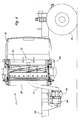
- coupling mechanism 10 may be used to attach cutting unit 11 to a lift arm 17 extending laterally from a mowing machine.
- the mowing machine may be generally adapted to cut grass on golf course fairways, athletic fields, or similar applications where high quality cutting is desired.
- the mowing machine may have a pair of front wheels 15 and a pair of rear wheels 25.
- the rear wheels may be steered and the front wheels may not be steered.
- the front wheels may be steered.
- Three, five or more cutting units are positioned side-by-side in two rows immediately in front of or behind the pair of front wheels.
- coupling mechanism 10 may connect cutting unit 11 to arm 17 which extends laterally from a mowing vehicle frame 29.
- Lift arm 17 may be a hollow L-shaped tube having a first end pivotably connected by bushings 34 to frame member 29, and a second end extending laterally from the frame when it is in the mowing position.
- the lift arm also may extend forwardly from the frame.
- Hydraulic cylinder 40 may be engaged to lift arm 17 to selectively pivot the lift arm to raise and lower the cutting unit.
- the hydraulic cylinder also may be adapted to apply a downforce to the lift arm for pressing the cutting unit against the ground during mowing.
- cutting unit 11 may include a generally cylindrical cutting reel rotatably supported between opposing side frames 13, 14.
- the reel may have spiral blades rotating on a reel shaft with a horizontal axis.
- the reel may have a width between about 45,72 centimetres (18 inches) and about 76,2 centimetres (30 inches), and a diameter between about 10,16 centimetres (4 inches) and about 25,4 centimetres (10 inches).
- the reel may be driven by an electric or hydraulic motor 35 mounted on the end of the reel, or by a belt or chain drive engaged to a motor.
- the cutting unit may include ground engaging front and rear support rollers 28, 30 which may help support the cutting unit at a proper height above the ground during mowing operations.
- the cutting reel's horizontal axis may be positioned less than about 71,12 centimetres (28 inches) from the horizontal axis of the pair of front wheels 15.
- grass catcher 18 may be carried by cutting unit 11 directly in front of the cutting unit.
- the grass catcher may be hooked to forward bar 64 which extends laterally across the front of the cutting unit and/or other front facing components of the cutting unit, and may be removable from the cutting unit to empty the clippings.
- the grass catcher may be a plastic enclosure having a width approximately the same as the cutting reel, and a single rear-facing opening 19 through which the grass clippings enter.
- the rear-facing opening may be generally oblong or rectangular.
- the opening may have an upper lip or edge 22 and a lower lip or edge.
- the lower lip or edge may be above the bottom surface 24 of the grass catcher so that grass clippings may be retained inside the grass catcher while mowing.
- the bottom surface may be lower than the lower lip or edge of the opening, so that grass clippings are easily retained in the grass catcher after entering through the opening.
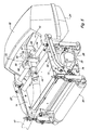
- coupling mechanism 10 may have a body 16 with a generally horizontal shaft 44 that extends rearwardly from the body.
- the horizontal shaft may be received within the end portion of lift arm 17.
- the horizontal shaft may have a double conical opening 52.
- a pin or internal projection in lift arm 17 may help engage and retain the horizontal shaft, and allow the horizontal shaft to pivot on a generally horizontal axis through a limited range of motion.
- the horizontal axis may be defined by the end portion of lift arm 17.
- the coupling mechanism may be engaged to forward bar 64 that extends laterally across the forward end of cutting unit 11 near the rear facing opening of the grass catcher.
- Forward bar 64 may be connected at its opposing ends to left and right yoke arms 56, 57.
- the yoke arms may be attached to side frames 13, 14 of the cutting unit.
- yoke arms 56, 57 may be connected to the side frames of a cutting unit at connection points 78.
- the connection points may be located between rollers 28 and 30 but closer to rear roller 30 than front roller 28, and may be behind the cutting unit's center of gravity.
- the front bar, along with the left and right yoke arms, form a yoke assembly secured to the cutting unit.
- one or more removable pins 58, 68 may be used to engage or disengage the coupling mechanism body 16 from forward bar 64.
- Each pin 58 may be aligned horizontally and each pin 68 may be aligned vertically when engaged to the coupling mechanism body. In the engaged position, the pins are completely or primarily positioned above forward bar 64.
- the coupling mechanism including the removable pins may hold and lock the cutting unit in a mowing position, a service position, or a transport position.
- horizontal pins 58 may be positioned in first openings 65 defined in a pair of laterally spaced plates 61, 62 which may be fixed as by welds to front bar 64.
- a cutting unit may be moved from the mowing position to the partially raised service or maintenance position of Fig. 3 .
- First or horizontal pins 58 may be removed from first openings 65, and arm 17 may be pivoted using hydraulic cylinder 40, preferably between about 7,62 cm (three inches) and about 30,48 cm (12 inches).
- horizontal pins 58 may be shifted inwardly by pivoting lever 90.
- end portions of the lever may engage ramp or cam surface 94 in coupling body 16, and the end portions are pressed or shifted inwardly toward each other.
- horizontal pins 58 shift inwardly with the end portions of lever 90, and become removed from first openings 65 in laterally spaced plates 61, 62.
- the cutting unit also may be allowed to pivot downwardly with respect to the coupling mechanism. In this position, the underside of the cutting unit is exposed forwardly for service. Horizontal pins 58 may be used to hold the cutting unit in the partially raised service or maintenance position by aligning the pins for insertion in second openings 66 in the pair of laterally spaced plates 61, 62. With horizontal pins 58 inserted in second openings 66, the cutting unit may be held against pivotal motion so that adjustments or maintenance may be done to the exposed underside of the cutting unit.
- the cutting unit may be partially raised and placed in the service position by use of the hydraulic cylinder.
- Lever 90 may be shifted past ramped portion 94 and onto a flatted portion where the lever may remain generally stationary.
- Horizontal pins 58 may be disengaged from first openings 65, and the cutting unit may be allowed to pivot downwardly when lift arm 17 raises the cutting unit for service.
- the lift arm raises or lifts the cutting unit off the ground, but the lift arm may continue to extend laterally from the mowing machine.
- the operator may pivot lever 90 to press or bias horizontal pins 58 outwardly against plates 61, 62.
- the operator may need to manually pivot the cutting unit forwardly slightly with respect to plates 61, 62 in order to align horizontal pins 58 with second openings 66.
- Horizontal pins 58 may be biased outwardly and will spring outwardly into second openings 66 when proper alignment is achieved.
- the biasing action of lever 90 eliminates the need for the operator to manually reinsert the horizontal pins at the same time he is pivoting the cutting unit to the proper alignment.
- the underside of the cutting unit may be accessible for adjustment of reel to bed knife clearance, cutting height, and other adjustments or repairs.
- lever 90 may be pivoted sufficiently to disengage the horizontal pins 58 from second openings 66 in the laterally spaced plates.
- the cutting unit's center of gravity 80 may pivot rearwardly to a position generally beneath front bar 64.
- the cutting unit may pivot rearwardly to its mowing position when the ground is contacted.
- the operator may shift lever 90 to bias the horizontal pins 58 outwardly so that they engage first openings 65 in plates 61, 62.
- a cutting unit may be moved to a fully raised or transport position by fully or completely pivoting lift arm 17 to an upright position.
- the lift arm In the fully raised or transport position, the lift arm does not extend laterally from the mowing machine, but has pivoted to an upright position from the mowing machine and may have a nearly or partially vertical orientation.
- horizontal pins 58 When a cutting unit is in the fully raised or transport position, horizontal pins 58 may remain in openings 65.
- the reel in the cutting unit may have a generally vertical alignment.
- the cutting units may be lifted so that they are within the track width of the mowing machine.
- the cutting units on the left and right of the second row may be raised to a transport position that is within the track width of rear wheels 25.
- the cutting units on the first row may be raised to a transport position within the track width of front wheels 15.
- a second or vertical pin 68 may confine forward bar 64 within a groove defined in the body portion 16 of the coupling mechanism. The vertical pin may be removed to allow the cutting unit to be removed from the coupling mechanism.
- the plates 61, 62 and removable pins 58, 68 are positioned in a plane above forward bar 64, and not below forward bar 64.
- the coupling mechanism will not block any part of the discharge zone between the cutting unit and the grass catcher, or will minimize the blockage.
- laterally spaced plates 61, 62 extend upwardly from forward bar 64.
- openings 65, 66 may be positioned above the centerline of forward bar 64, and coupling mechanism body 16 also may be positioned above forward bar 64.
- the present invention significantly reduces the coupling mechanism cost and complexity. It has been found that a cutting unit with a reel axis positioned within about 45,72 cm (18 inches) of the outer tire surface of the front pair of wheels, or within about 71,12 cm (28 inches) from the horizontal centerline of the front pair of non-steerable wheels, will not skid or tear the turf when the mowing machine turns. As a result, the coupling mechanism may be simplified and reduced in cost, and the improved coupling mechanism may be positioned so that it does not block the grass discharge zone to the grass catcher. Thus, in one embodiment, coupling mechanism 11 may be positioned above the forward bar such that it does not block the discharge stream from the cutting unit to the grass catcher.
Landscapes
- Life Sciences & Earth Sciences (AREA)
- Environmental Sciences (AREA)
- Harvester Elements (AREA)
Claims (10)
- Kopplungsmechanismus (10) zur Befestigung einer Mäherschneideinheit (11) vorzugsweise der Spindelart an einen Mäher, mit einer vorderen Stange (64), die sich quer über den vorderen Teil der Mäherschneideinheit (11) erstreckt, einem Kopplungskörper (16) mit einer sich nach hinten erstreckenden Welle (44), die mit einem sich von dem Mäher lateral erstreckenden Hubarm (17) in Eingriff gebracht werden kann; wobei die sich nach hinten erstreckende Welle (44) an einer durch den Hubarm (17) definierten allgemein horizontalen Achse schwenkt, dadurch gekennzeichnet, dass die vordere Stange (64) ein Paar sich davon nach oben erstreckender Platten (61, 62), wobei jede Platte (61, 62) eine erste Öffnung (65) und eine zweite Öffnung (66) über der vorderen Stange (64) aufweist, und mindestens einen horizontalen Stift (58) aufweist, der mit dem Kopplungskörper (16) und den ersten Öffnungen (65) in den Platten (61, 62) in Eingriff gebracht werden kann, um die Mäherschneideinheit (11) in einer Mähstellung oder einer vollständig angehobenen Transportstellung zu halten, und mit dem Kopplungskörper (16) und den zweiten Öffnungen (66) in den Platten (61, 62) in Eingriff gebracht werden kann, um die Mäherschneideinheit (11) in einer teilweise angehobenen Wartungsstellung zu halten.
- Kopplungsmechanismus nach Anspruch 1, gekennzeichnet durch einen vertikalen Stift (68), der mit einer Nut im Kopplungskörper (16) in Eingriff gebracht werden kann, um den Kopplungskörper (16) an die vordere Stange (64) der Mäherschneideinheit (11) zu halten, und außer Eingriff gebracht werden kann, um den Kopplungskörper (16) von der vorderen Stange (64) der Mäherschneideinheit (11) zu lösen.
- Kopplungsmechanismus nach Anspruch 1 oder 2, gekennzeichnet durch einen Hebel (90) zum gezielten Ineingriffbringen des horizontalen Stifts (58) mit den ersten Öffnungen (65) oder den zweiten Öffnungen (66).
- Kopplungsmechanismus nach einem oder mehreren der vorhergehenden Ansprüche, gekennzeichnet durch mindestens einen Hydraulikzylinder (40) zum Anlegen einer Abwärtskraft an den Hubarm (17), wenn sich die Mäherschneideinheit (11) in der Mähstellung befindet, und/oder zum Nachobenschwenken des Hubarms (17), um die Schneideinheit (11) in die teilweise angehobene Wartungsstellung zu heben, und des weiteren zum Schwenken des Hubarms (17) weiter nach oben, um die Schneideinheit (11) in die vollständig angehobene Transportstellung zu bewegen.
- Mäher mit einem vorderen Paar Räder (15) auf einer vorderen Radachse und Spurweite und einem hinteren Paar Räder (25) mit einer hinteren Radachse und Spurweite; mehreren vorzugsweise spindelförmigen Schneideinheiten (11), die vor und hinter dem vorderen Paar Räder (15) positioniert sind; wobei jede Schneideinheit (11) eine sich quer über den vorderen Teil der Schneideinheit (11) erstreckende vordere Stange (64) und einen am vorderen Ende der Schneideinheit (11) lösbar befestigten Grasfangbehälter (18) aufweist; einem an dem Mäher angelenkten Hubarm (17), der zwischen einer lateral ausgestreckten Stellung, einer teilweise angehobenen Stellung und einer vollständig angehobenen Stellung schwenkbar ist; gekennzeichnet durch einen Kopplungsmechanismus (10) nach einem oder mehreren der vorhergehenden Ansprüche, der die vordere Stange (64) einer Schneideinheit (11) mit dem Hubarm (17) lösbar verbindet.
- Mäher nach Anspruch 5, dadurch gekennzeichnet, dass die mehreren Schneideinheiten (11) eine allgemein horizontale Achse aufweisen, wobei die horizontale Achse jeder Schneideinheit (11) vorzugsweise innerhalb von 71,12 Zentimetern (28 Zoll) der vorderen Radachse positioniert ist.
- Mäher nach Anspruch 5 oder 6, wobei der Grasfangbehälter (18) an der vorderen Stange (64) eingehakt ist und/oder eine vorzugsweise längliche, nach hinten weisende Öffnung (19) aufweist, die vorzugsweise eine obere Lippe oder einen oberen Rand (22), eine untere Lippe oder einen unteren Rand und eine Unterseite (24) unter der unteren Lippe oder dem unteren Rand aufweist.
- Mäher nach einem oder mehreren der Ansprüche 5 bis 7, dadurch gekennzeichnet, dass die Schneideinheit (11) an einem Ende des Hubarms (17) zum Schwenken an einer durch das Ende des Hubarms (17) definierten horizontalen Achse befestigt ist.
- Mäher nach einem oder mehreren der Ansprüche 5 bis 8, dadurch gekennzeichnet, dass jeder Kopplungsmechanismus (10) in erster Linie über der vorderen Stange (64) positioniert ist.
- Mäher nach einem oder mehreren der Ansprüche 5 bis 9, dadurch gekennzeichnet, dass die Schneideinheiten (11) in der Transportstellung innerhalb der hinteren Radspur liegen.
Applications Claiming Priority (1)
| Application Number | Priority Date | Filing Date | Title |
|---|---|---|---|
| US11/046,309 US7331166B2 (en) | 2005-01-28 | 2005-01-28 | Coupling mechanism for mower cutting units |
Publications (2)
| Publication Number | Publication Date |
|---|---|
| EP1685758A1 EP1685758A1 (de) | 2006-08-02 |
| EP1685758B1 true EP1685758B1 (de) | 2008-02-20 |
Family
ID=35929954
Family Applications (1)
| Application Number | Title | Priority Date | Filing Date |
|---|---|---|---|
| EP05112443A Expired - Fee Related EP1685758B1 (de) | 2005-01-28 | 2005-12-20 | Kopplungsmechanismus und Mäher |
Country Status (3)
| Country | Link |
|---|---|
| US (1) | US7331166B2 (de) |
| EP (1) | EP1685758B1 (de) |
| DE (1) | DE602005004885T2 (de) |
Families Citing this family (14)
| Publication number | Priority date | Publication date | Assignee | Title |
|---|---|---|---|---|
| ATE355731T1 (de) * | 2000-06-26 | 2007-03-15 | Toro Co | Spindelmäher |
| US7971417B2 (en) | 2006-12-05 | 2011-07-05 | Deere & Company | Elective down pressure system for cutting units of grass mowing machine |
| JP2009027961A (ja) * | 2007-07-26 | 2009-02-12 | Kyoeisha Co Ltd | 歩行式芝刈機、及びキャッチャーフレーム装置 |
| US7637090B2 (en) | 2007-10-17 | 2009-12-29 | Deere & Company | Roller configuration having reduced overlap for a grass mowing machine |
| US8407976B2 (en) * | 2008-01-25 | 2013-04-02 | Deere & Company | Grass catcher mounting device for reel mower cutting unit |
| US7841158B2 (en) * | 2008-02-19 | 2010-11-30 | Textron Innovations Inc. | Universal yoke assembly for a turf maintenance vehicle |
| AU2009261926B2 (en) * | 2008-06-27 | 2013-01-31 | The Toro Company | Reel mower |
| US7765779B2 (en) * | 2008-08-18 | 2010-08-03 | Deere & Company | Latch mechanism for retaining grass catcher on reel mower cutting unit |
| US7845152B2 (en) * | 2008-10-30 | 2010-12-07 | Deere & Company | Grass catcher retaining device for reel mower cutting unit |
| US8745838B2 (en) | 2011-06-23 | 2014-06-10 | Deere & Company | Ball joint assembly for attaching cutting unit to yoke |
| US8777508B2 (en) | 2011-06-23 | 2014-07-15 | Deere & Company | Cutting unit mounting device |
| US9854740B2 (en) * | 2015-06-27 | 2018-01-02 | The Toro Company | Reel mower with reel cutting units having grass collecting baskets with deflectable bottom portions responsive to movement of the cutting units |
| US10390488B2 (en) * | 2017-08-08 | 2019-08-27 | Deere & Company | Triplex greensmower lift system |
| WO2020053670A1 (en) * | 2018-09-14 | 2020-03-19 | Husqvarna Ab | Multi-position locking mechanism for a riding lawn care vehicle |
Family Cites Families (19)
| Publication number | Priority date | Publication date | Assignee | Title |
|---|---|---|---|---|
| US3408801A (en) * | 1965-10-22 | 1968-11-05 | Toro Mfg Corp | Non-spill grass catcher |
| US3824772A (en) * | 1972-01-25 | 1974-07-23 | Hahn Inc | Turf maintenance machine |
| US4644737A (en) * | 1983-09-20 | 1987-02-24 | Brouwer Turf Equipment Limited | Mower |
| GB2178634B (en) * | 1985-06-10 | 1988-10-19 | Ransomes Sims & Jefferies Plc | Grass cutting machine |
| CA1269848A (en) * | 1986-04-30 | 1990-06-05 | William T. Arnold | Grass collection system for mower |
| US4769976A (en) * | 1987-02-11 | 1988-09-13 | The Toro Company | Method and apparatus for supporting a reel unit |
| US5042236A (en) * | 1990-02-08 | 1991-08-27 | The Toro Company | Cutting reel suspension with adjustable spring downloading |
| US5297378A (en) * | 1992-05-13 | 1994-03-29 | Deere & Company | Suspension mechanism for reel mowers |
| US5343680A (en) * | 1992-09-03 | 1994-09-06 | Deere & Company | Suspension mechanism for reel mowers |
| US5293729A (en) * | 1992-10-07 | 1994-03-15 | Deere & Company | Pivot mechanism for reel mower cutting units |
| US5623817A (en) * | 1995-01-20 | 1997-04-29 | The Toro Company | Operating unit joint for turf maintenance equipment |
| US5533326A (en) * | 1995-02-24 | 1996-07-09 | The Toro Company | Reel mower |
| US5865016A (en) * | 1997-02-07 | 1999-02-02 | Ransomes America Corporation | Release mechanism for cutting head of a gang mower |
| EP0941023A1 (de) * | 1997-08-29 | 1999-09-15 | The Toro Company | Befestigungssystem fur mehrzweckbedieneinheit |
| US5970690A (en) * | 1997-10-24 | 1999-10-26 | Ransomes America Corporation | Leveling apparatus for a cutting head of a mower |
| US6341478B1 (en) * | 1999-06-14 | 2002-01-29 | The Toro Company | Steerable cutting unit with steerable and level lift grass catcher |
| US6237313B1 (en) * | 1999-08-13 | 2001-05-29 | Deere & Company | Grass catcher support assembly for reel mower cutting unit |
| GB0000790D0 (en) * | 2000-01-14 | 2000-03-08 | Oliver Marcus J | Modular unit for mounting on a grass treatment machine |
| US7287363B2 (en) * | 2004-04-20 | 2007-10-30 | Deere & Company | Riding mower having multiple cutting units |
-
2005
- 2005-01-28 US US11/046,309 patent/US7331166B2/en not_active Expired - Lifetime
- 2005-12-20 EP EP05112443A patent/EP1685758B1/de not_active Expired - Fee Related
- 2005-12-20 DE DE602005004885T patent/DE602005004885T2/de not_active Expired - Lifetime
Also Published As
| Publication number | Publication date |
|---|---|
| DE602005004885D1 (de) | 2008-04-03 |
| EP1685758A1 (de) | 2006-08-02 |
| US7331166B2 (en) | 2008-02-19 |
| US20060168929A1 (en) | 2006-08-03 |
| DE602005004885T2 (de) | 2009-02-19 |
Similar Documents
| Publication | Publication Date | Title |
|---|---|---|
| EP1685758B1 (de) | Kopplungsmechanismus und Mäher | |
| CA2729005C (en) | Reel mower | |
| US6341478B1 (en) | Steerable cutting unit with steerable and level lift grass catcher | |
| US5528886A (en) | Hitching arrangement for a mower deck | |
| CA2094959C (en) | Pivot mechanism for reel mower cutting units | |
| US5280695A (en) | Wide area lawnmower | |
| US20090188230A1 (en) | Grass catcher mounting device for reel mower cutting unit | |
| CN109379985B (zh) | 三联割草机的升降系统 | |
| CN109379988B (zh) | 三联割草机的开放式脚平台 | |
| US5233817A (en) | Cutter annex to cutter head of lawn mower | |
| EP2361493B1 (de) | Spindelmäher-Schneideeinheit | |
| GB1583983A (en) | Harvesting machines | |
| US11212961B2 (en) | Drive-over mower deck with retractable front rollers | |
| US11032972B2 (en) | Triplex greensmower open foot platform cover | |
| JP3648400B2 (ja) | 芝刈機 | |
| JP3383581B2 (ja) | 乗用型草刈機 | |
| CA2157436A1 (en) | Lawn mower with rotatable wheels | |
| JP2021013307A (ja) | 乗用草刈機のフロントバンパー |
Legal Events
| Date | Code | Title | Description |
|---|---|---|---|
| PUAI | Public reference made under article 153(3) epc to a published international application that has entered the european phase |
Free format text: ORIGINAL CODE: 0009012 |
|
| AK | Designated contracting states |
Kind code of ref document: A1 Designated state(s): AT BE BG CH CY CZ DE DK EE ES FI FR GB GR HU IE IS IT LI LT LU LV MC NL PL PT RO SE SI SK TR |
|
| AX | Request for extension of the european patent |
Extension state: AL BA HR MK YU |
|
| 17P | Request for examination filed |
Effective date: 20070202 |
|
| AKX | Designation fees paid |
Designated state(s): DE GB |
|
| GRAP | Despatch of communication of intention to grant a patent |
Free format text: ORIGINAL CODE: EPIDOSNIGR1 |
|
| GRAS | Grant fee paid |
Free format text: ORIGINAL CODE: EPIDOSNIGR3 |
|
| GRAA | (expected) grant |
Free format text: ORIGINAL CODE: 0009210 |
|
| AK | Designated contracting states |
Kind code of ref document: B1 Designated state(s): DE GB |
|
| REG | Reference to a national code |
Ref country code: GB Ref legal event code: FG4D |
|
| REF | Corresponds to: |
Ref document number: 602005004885 Country of ref document: DE Date of ref document: 20080403 Kind code of ref document: P |
|
| PLBE | No opposition filed within time limit |
Free format text: ORIGINAL CODE: 0009261 |
|
| STAA | Information on the status of an ep patent application or granted ep patent |
Free format text: STATUS: NO OPPOSITION FILED WITHIN TIME LIMIT |
|
| 26N | No opposition filed |
Effective date: 20081121 |
|
| PGFP | Annual fee paid to national office [announced via postgrant information from national office to epo] |
Ref country code: DE Payment date: 20191120 Year of fee payment: 15 |
|
| PGFP | Annual fee paid to national office [announced via postgrant information from national office to epo] |
Ref country code: GB Payment date: 20200102 Year of fee payment: 15 |
|
| REG | Reference to a national code |
Ref country code: DE Ref legal event code: R119 Ref document number: 602005004885 Country of ref document: DE |
|
| GBPC | Gb: european patent ceased through non-payment of renewal fee |
Effective date: 20201220 |
|
| PG25 | Lapsed in a contracting state [announced via postgrant information from national office to epo] |
Ref country code: DE Free format text: LAPSE BECAUSE OF NON-PAYMENT OF DUE FEES Effective date: 20210701 Ref country code: GB Free format text: LAPSE BECAUSE OF NON-PAYMENT OF DUE FEES Effective date: 20201220 |