EP1685598B1 - Automated material handling system - Google Patents
Automated material handling system Download PDFInfo
- Publication number
- EP1685598B1 EP1685598B1 EP04780607A EP04780607A EP1685598B1 EP 1685598 B1 EP1685598 B1 EP 1685598B1 EP 04780607 A EP04780607 A EP 04780607A EP 04780607 A EP04780607 A EP 04780607A EP 1685598 B1 EP1685598 B1 EP 1685598B1
- Authority
- EP
- European Patent Office
- Prior art keywords
- container
- track
- transport
- motor
- section
- Prior art date
- Legal status (The legal status is an assumption and is not a legal conclusion. Google has not performed a legal analysis and makes no representation as to the accuracy of the status listed.)
- Expired - Lifetime
Links
Images




Classifications
-
- H—ELECTRICITY
- H10—SEMICONDUCTOR DEVICES; ELECTRIC SOLID-STATE DEVICES NOT OTHERWISE PROVIDED FOR
- H10P—GENERIC PROCESSES OR APPARATUS FOR THE MANUFACTURE OR TREATMENT OF DEVICES COVERED BY CLASS H10
- H10P72/00—Handling or holding of wafers, substrates or devices during manufacture or treatment thereof
- H10P72/50—Handling or holding of wafers, substrates or devices during manufacture or treatment thereof for positioning, orientation or alignment
-
- H—ELECTRICITY
- H10—SEMICONDUCTOR DEVICES; ELECTRIC SOLID-STATE DEVICES NOT OTHERWISE PROVIDED FOR
- H10P—GENERIC PROCESSES OR APPARATUS FOR THE MANUFACTURE OR TREATMENT OF DEVICES COVERED BY CLASS H10
- H10P72/00—Handling or holding of wafers, substrates or devices during manufacture or treatment thereof
- H10P72/70—Handling or holding of wafers, substrates or devices during manufacture or treatment thereof for supporting or gripping
- H10P72/76—Handling or holding of wafers, substrates or devices during manufacture or treatment thereof for supporting or gripping using mechanical means, e.g. clamps or pinches
- H10P72/7602—Handling or holding of wafers, substrates or devices during manufacture or treatment thereof for supporting or gripping using mechanical means, e.g. clamps or pinches the wafers being placed on a robot blade or gripped by a gripper for conveyance
-
- B—PERFORMING OPERATIONS; TRANSPORTING
- B65—CONVEYING; PACKING; STORING; HANDLING THIN OR FILAMENTARY MATERIAL
- B65G—TRANSPORT OR STORAGE DEVICES, e.g. CONVEYORS FOR LOADING OR TIPPING, SHOP CONVEYOR SYSTEMS OR PNEUMATIC TUBE CONVEYORS
- B65G13/00—Roller-ways
-
- B—PERFORMING OPERATIONS; TRANSPORTING
- B65—CONVEYING; PACKING; STORING; HANDLING THIN OR FILAMENTARY MATERIAL
- B65G—TRANSPORT OR STORAGE DEVICES, e.g. CONVEYORS FOR LOADING OR TIPPING, SHOP CONVEYOR SYSTEMS OR PNEUMATIC TUBE CONVEYORS
- B65G37/00—Combinations of mechanical conveyors of the same kind, or of different kinds, of interest apart from their application in particular machines or use in particular manufacturing processes
- B65G37/02—Flow-sheets for conveyor combinations in warehouses, magazines or workshops
-
- H—ELECTRICITY
- H10—SEMICONDUCTOR DEVICES; ELECTRIC SOLID-STATE DEVICES NOT OTHERWISE PROVIDED FOR
- H10P—GENERIC PROCESSES OR APPARATUS FOR THE MANUFACTURE OR TREATMENT OF DEVICES COVERED BY CLASS H10
- H10P72/00—Handling or holding of wafers, substrates or devices during manufacture or treatment thereof
- H10P72/30—Handling or holding of wafers, substrates or devices during manufacture or treatment thereof for conveying, e.g. between different workstations
- H10P72/32—Handling or holding of wafers, substrates or devices during manufacture or treatment thereof for conveying, e.g. between different workstations between different workstations
- H10P72/3218—Conveying cassettes, containers or carriers
-
- H—ELECTRICITY
- H10—SEMICONDUCTOR DEVICES; ELECTRIC SOLID-STATE DEVICES NOT OTHERWISE PROVIDED FOR
- H10P—GENERIC PROCESSES OR APPARATUS FOR THE MANUFACTURE OR TREATMENT OF DEVICES COVERED BY CLASS H10
- H10P72/00—Handling or holding of wafers, substrates or devices during manufacture or treatment thereof
- H10P72/30—Handling or holding of wafers, substrates or devices during manufacture or treatment thereof for conveying, e.g. between different workstations
- H10P72/32—Handling or holding of wafers, substrates or devices during manufacture or treatment thereof for conveying, e.g. between different workstations between different workstations
- H10P72/3222—Loading to or unloading from a conveyor
-
- H—ELECTRICITY
- H10—SEMICONDUCTOR DEVICES; ELECTRIC SOLID-STATE DEVICES NOT OTHERWISE PROVIDED FOR
- H10P—GENERIC PROCESSES OR APPARATUS FOR THE MANUFACTURE OR TREATMENT OF DEVICES COVERED BY CLASS H10
- H10P95/00—Generic processes or apparatus for manufacture or treatments not covered by the other groups of this subclass
Definitions
- the present invention relates to material handling systems and, more particularly, to a automated material handling systems for transporting semiconductor workpiece holding canisters or containers in processing facilities.
- FIG. 1 there is shown a perspective view of a representative conventional semiconductor fabrication facility 1.
- the fabrication or fab facility 1 has a number of fab bays 2 arranged in the facility in a desired array.
- the fab bays 2 include vacuum and atmospheric processing tools 3, 4 where the semiconductor devices are manufactured.
- the fab facility 1 also has an automated material handling system installed therein for transporting the semiconductor material to and from the semiconductor devices.
- the conventional material handling system in the fab facility shown in Fig. 1 generally includes stockers 5, interbay transport system 6, and intrabay transport system 7.
- the stockers 5, used to store the semiconductor devices between various processing evolutions are located adjacent the opening of the fab bays 2 on a common passage linking the fab bays 2.
- the interbay transport system 6 is installed in the common passage and connects the stockers 5. This allows semiconductor devices to be transported, by suitable vehicles traveling on the interbay transport system 5 between stockers 5.
- the automated material handling system is one of the significant factors in the efficient fabrication process in the fab facility.
- a significant amount of time is consumed transporting the semiconductor material with the material handling system, to and from the processing tools.
- the larger the processing facility, in order to achieve economies of scale the greater the time consumed transporting semiconductor material with the material handling system to and from processing tools within the facility.
- the size of the facility itself becomes limited by the speed and efficiency with which the material handling system is capable of delivering semiconductor material to the processing tools for processing, and removing the processed workpieces to stockers for ultimate completion and shipping. Attempts to increase efficiency by reducing transport time have been made, and have achieved success in cases.
- the AeroloaderTM automated material handling system from Brooks Automation, Inc.
- FIG. 1A is a partial perspective view of a portion of a conventional conveyor system such as for example disclosed in international patent publication WO 03/038,869 , for transporting a conventional semiconductor workpiece container.
- the container F shown in Fig. 1A is conventional container such as a conventional FOUP or SMIF container.
- Fig. 1A shows a portion of a conveyor track CT of the conventional system.
- the conventional conveyor track CT in Fig. 1A may be representative of one or more of the tracks 7A-7F of the system in Fig. 1 .
- the conventional conveyor track CT in Fig. 1A comprises a pair of rails R1, GR.
- the conventional conveyor system uses a pallet P as shown to support the conventional container F on the conveyor track CT.
- the pallet P has a support area on which the container F may be seated.
- the pallet P may also have runners P1, P2 to allow the pallet P to ride over the conveyor rails R1, GR.
- One runner P1 may be flat, defining a rolling surface for rollers RR in rail R1.
- the other runner P2 may have a guide slot, or guide key mated to the rail GR to guide the pallet P along the rails during transport.
- 1A may include powered rollers RR to drive the pallet P on the rails.
- the rollers RR are coupled by a suitable transmission, such as an endless belt, to a drive motor capable of turning the rollers.
- the motor rotates the rollers RR and the frictional contact between rollers and pallet runner P1 causes the pallet to move.
- the other runner P2 of the pallet P slidably mated to rail GR, guides the pallet as it is moved down the rails maintaining alignment between the pallet runner P1 and drive rollers RR.
- alignment between the pallet runner, and hence between rail GR, and the contact line of the line of rollers RR in rail R1 should be highly accurate in the conventional mechanical driven conveyor track to allow the pallet to be driven true to the track.
- the conventional system is not misalignment tolerant. Misalignment, may generate a force on the pallet orthogonal to the track, resulting in undesired friction, possible binding, between runner P2 and rail GR and in increased potential for particulate contamination on the container.
- alignment between rollers RR on rail R1 should be precise to avoid a contact/drive line between rollers and runner P1 that is angled relative to the track.
- the conventional conveyor system may include a position locating system for the pallet.
- the conventional locating system includes providing one of the rails R1 with sensors (e.g. electronic, electro-optical) capable of detecting a feature on the pallet P when the pallet is in a predetermined area relative to the sensors. The sensors are equally distributed along the rails.
- the rollers RR alone or in combination with the drive motors may have an encoder identifying the rotation of the rollers.
- the position of the pallet P at any time is established using the combination of data from the rail sensors and rollers.
- the conventional locating system is subject to inaccuracies because of possible slippage between rollers RR and pallet during acceleration/deceleration, as well as that locating the pallet between sensors is dependent merely on counting roller revolutions.
- the combination of the limitations of frictional drive and the conventional position location system deprive the conventional conveyor track of effective fine position control.
- a further problem of the convention conveyor system is that movement of semiconductor material containers on the transport system is dependent on availability of transport pallets.
- the present invention provides the desired efficiency for the material handling system, as will be described in greater detail below.
- US patent 6,468,021 B1 and US patent 5,443,346 already show semiconductor work piece processing systems comprising at least one processing tool for processing semiconductor work pieces; a container for holding at least one semiconductor work piece therein for transport to and from the processing tool; a first transport section connecting to the processing tool for transporting the container to and from the processing tool; and a second transport section connected to the first transport section for transporting the container to and from the first transport section; wherein the first transport section is a vehicle based section having a transport vehicle capable of holding the container and moving along a first track of the first transport section, and the second transport section is a conveyor section and has a second track with at last one support element of the second track adapted to interface with the container for movably supporting the container from the second track and allowing the container to move relative to the first track, and wherein the second transport section has a motor connected to the second track for aligning the container on the second track with the transport vehicle on the first track.
- the vehicle based system is also arranged orthogonally to the conveyor based system and also only serves to transport the containers arriving on the conveyor system for "the last meter" to the processing stations.
- FIG. 2 there is shown a schematic plan view of an automated material handling system 10 incorporating features of the present invention and processing tools P in a processing facility.
- a schematic plan view of an automated material handling system 10 incorporating features of the present invention and processing tools P in a processing facility.
- the present invention will be described with reference to the single embodiment shown in the drawings, it should be understood that the present invention can be embodied in many alternate forms of embodiments.
- any suitable size, shape or type of elements or materials could be used.
- the automated material handling system 10 generally includes a first transport system section 12 and a second transport system section 14.
- the transport system sections 12, 14 of the automated material handling system 10 are generally arranged to allow transportation of semiconductor workpieces, such as for example, 200 mm wafers, 300 mm wafers, flat display panels and similar such items, to and from processing tools P in the processing facility.
- the processing tools P, and the facility are generally similar to the facility 1 and tools 4 described before and shown in Fig. 1 .
- the configuration of the automated material handling system 10 shown in Fig. 2 is a representative configuration, and the automated material handling system 10 may be disposed in any suitable configuration to accommodate any desired layout of process tools in a processing facility.
- One transport system section 12 of the automated material handling system 10 is a vehicle based system.
- the transport system section 12 comprises tracks 16 and transport vehicles 200 (see also Fig. 4 ).
- the transport vehicles 200 are capable of holding a semiconductor workpiece container (not shown in Fig. 1 ) and travel along the tracks 16 of transport section 12.
- the transport vehicles 200 thus move the workpiece containers along tracks 16 between processing tools, or between processing tools and stockers (not shown) similar to stockers 5 shown in Fig. 1 .
- the other transport system section 14 of the automated material handling system 10 is not a vehicle based transport system.
- Transport system section 14 is a conveyor based or high speed (relative to a vehicle based system) mass delivery system.
- Transport system section 14 comprises a track or run 18 capable of directly conveying, without the use of intermediate transport vehicles, semiconductor workpiece containers at high speed as will also be described in greater detail below.
- the track 18, as shown schematically in Fig. 2 may extend along at least some portions of track 16 of the other transport system section 12.
- the track 18 of transport system section 14 may also span between different portions of track 16 of transport system section 12.
- the semiconductor workpiece containers may be transferred as desired between the track 18 of section 14 and transport vehicles 200 (see Fig. 3 ) on track 16 of section 12.
- the automated material handling system 10 may transport semiconductor workpiece containers using any desired combination of the first and second transport system sections 12, 14 in order to achieve the most efficient delivery and return of semiconductor workpiece containers from the processing tools.
- a suitable controller C is connected to the first and second transport system sections 12, 14 to control operation of the sections.
- the second transport system section 14 may also provide a distributed storage or buffer for the automated material handling system as will be described in greater detail below.
- the first system section 12 of the automated material handling system 10 generally includes track 16 and transport vehicles 200, as noted above.
- System section 12 may be generally similar to the automated material handling system described in US-A-2004181929 .
- the track 16 of system section 12 may be arranged into interbay 20, 22, 24 and intrabay 26, 28, 30 portions or branches.
- the intrabay branches 26, 28, 30 of the track may extend within individual fabrication bays (similar to the bays shown in Fig. 1 ) of the fab facility.
- the interbay branches 20, 22, 24 may extend within corridors or passages connecting the fabrication bays, and interconnect two or more intrabay branches 26, 28, 30 to each other.
- the first system section of the automated material handling system may have any suitable number of interbay and intrabay transport portions.
- the interbay transport branches 20, 22, 24 of the embodiment shown in Fig. 3 are substantially parallel to each other, though in alternate embodiments different interbay branches may not be parallel. Indeed, interbay transport branches may not connect all fab bays and may have any shape.
- the present invention encompasses any interbay transport system arranged in any desired manner to connect any desired number of fab bays.
- the interbay transport branches 20, 22, 24 are generally similar to each other, and will be described below with specific reference to the central portions 20.
- the interbay transport branch 20 may be made up of interbay transport segments or elements 20A-20B. In the embodiment shown in Fig. 2 , there are two segments 20A-20B for example purposes only, and in alternate embodiments the interbay transport branch may have any desired number of segments.
- Each segment 20A-20B is of sufficient length to span between two adjoining fab bays and specifically between adjacent portions of the intrabay transport system.
- segment 20A spans between adjoining intrabay port ions 26, 28.
- the span of each segment may be different.
- each segment 20A-20B may have multiple transport paths 19A-21A, 19B-21B, 19C-21C provided by any suitable table means (as will be described below) for transport vehicles (not shown), allowing the vehicles to traverse the segment.
- the transport paths of each segment are arranged to allow substantially simultaneous bi-directional travel of the transport vehicles on the segment (in directions indicated by arrows X1, X2).
- each segment 20A-20B may have two transport paths 19A-21A, 19B-21B extending between the ends of the segment.
- One path such as for example 19A, 19B, may be used by transport vehicles to travel in one direction (indicated by arrow X 1 ) and the other path, 21A-21B, may be used for travel in the opposite direction (indicated by arrow X 2 ).
- the travel paths may be dedicated to a given direction of travel or the direction of travel may be switched as desired according to a transport algorithm to suit transport loading conditions.
- transport path 19A of segment 20A may at first be used for vehicles traveling in the direction indicated by arrow X 1 in Fig. 2 .
- path 21A provides for travel in direction X 2 .
- travel direction for path 19A may be changed to direction X 2 , path 21A then becoming used for X 1 travel.
- travel direction need not be the same for similar paths 19A-19B, 21A-21C of each segment.
- transport path 21A may be used for travel direction X 2
- transport path 21B may be used for the opposite travel direction X 1 . This ability is provided by the interbay transport segments 22A-22C in this embodiment because as seen in Fig.
- each segment 20A-20B has a junction 34, 36, 38 at corresponding opposite ends of the segment.
- segment 20A has a junction 34 at one end 32A and another junction 36 at the opposite end 32B.
- the respective travel paths 19A-19B, 21A-21B of each segment 20A-20B substantially intersect at each corresponding junction 34, 36, 38.
- the junctions 36 between segments are used to connect the adjoining segments to each other. Junction 36 connects adjoining ends 32B-32C of segments 20A, 20B.
- Junction 36 may further allow ties between same or different transport paths of the connected segments.
- junction 36 may be used to tie transport path 19A of segment 20A to the transport path 21B of segment 20B thereby allowing transport vehicles to cross between paths 21B and 19A of the adjoining segments.
- any other suitable configuration of segments and junctions interconnecting segments may be used.
- the intrabay branches 26, 28, 30 are substantially similar to the interbay branches 20, 22, 24. Still referring to Fig. 2 as noted before, the intrabay transport is also made up of three branches for example purposes. Each branch may comprise a single transport segment or element, or may comprise a number of interlinked segments. In the embodiment shown in Fig. 2 , each branch has two segments 26A-26B, 28A-28B, 30A-30B. Each branch segment 26A-30B may extend within a single fab bay or may be further branched to other fab bays.
- the intrabay transport segments 26A-26B, 28A-28B and 30A-30B are generally similar to each other and hence are schematically illustrated the same in Fig. 2 .
- Each of the segments 26A-26B, 28A-28B, 30A-30B has multiple transport paths, similar to the interbay segments 20A, 20B described before, allowing substantially simultaneous bidirectional travel of transport vehicles along each segment.
- the transport paths of each segment for example, paths 25A, 27A of segment 26A, may converge towards each other at opposite ends 40A, 42A of the segment.
- junction 34 is the terminus of interbay transport paths 19A, 21A of an interbay transport segment 20A.
- the interbay transport paths 19A, 21A may be unified with the intrabay transport paths 25A, 27A of the intrabay transport segment 26A.
- the transport paths such as for example, paths 26A, 27A of segment 26A, terminate in a junction 44 at the far end 42A.
- Junction' 44 ties in the transport paths to interbay transport segment 22A.
- junctions may tie the transport paths of intrabay segments 26B-30B to the outer interbay transport segments 24A-24B.
- the intrabay transport segments may have any other suitable arrangement.
- FIG. 4 is a partial perspective view of a representative portion of an interbay or intrabay transport branch showing one suitable example of the types of handling system materials that may be used for the automated material handling system 10.
- the interbay transport segments 20A-20B (only parts of segments 20A, 20B are shown in Fig. 4 for example purposes) are formed using an overhead rail system such as the AeroloaderTM system available from Brooks Automation, Inc.
- each transport path 19A-19B, 21A-21B is provided by a corresponding rail or track.
- the tracks may be mounted to the fab facility overhead.
- Figs. 6A-6B there are shown respectively partial front and side elevation views of tracks 20A and a transport vehicle 200.
- Fig. 4 shows a third track 23A, 23B for each segment (not shown in Fig. 2 for clarity) which provides a high speed or "fly-through" transport path for each segment.
- the tracks converge at the junction 36 between the adjoining segments.
- junction 32 includes a turntable 202, though any suitable track switching device may be used.
- the turntable has three positions to tie the diametrically opposed track ends of the respective transport paths 21A-19B, 23A-23B, 19A-21B. When the turntable is positioned in one of these positions, a transport vehicle 200 may cross between diametrically opposed track ends without moving the turntable.
- the transport vehicle may be positioned onto the turntable, and the turntable may be rotated as desired to allow the transport vehicle to move from any track 19A, 23A, 21A of one segment to any other track 19B, 23B, 21B of the connected segment.
- the movement of the turntable may be automated, controlled by a suitable program from the central processor of the system.
- Automated overhead transport vehicles 200 such as the AeroloaderTM system shuttles are mounted on one of the tracks.
- the transport vehicle 200 may be sell propelled to autonomously travel on the corresponding rail forming each of the travel paths. Each vehicle travels on the desired transport paths according to a transport algorithm which may be preprogrammed into vehicle memory (not shown) or loaded from a central processor (not shown) operating the automated material handling system. In this embodiment, though any other suitable type of transport vehicle may be used.
- the transport vehicle 200 may have a transport section 204 (see Figs. 6A-6B ) and a payload section 206.
- the transport section 240 includes suitable wheels/rollers (not shown) to support and move the vehicle on the track.
- the transport section may also include a power source and motor for driving the vehicle along the track.
- the payload section 206 is mounted or otherwise supported from the transport section, and in this embodiment is suspended below the transport section (see Figs. 6A-6B ).
- the payload section 206 may include a hoist 208, in this embodiment schematically depicted as having gripper arms, capable of capturing and raising/lowering a workpiece holding container 151.
- Figs. 6A-6B show a representative workpiece storage container 151 that may be used with the handling system 10 (and which will be described in greater detail below) located in a position where the hoist 208 of the transport vehicle is capable of engaging the container 151.
- the storage container 151 may be in a storage area (not shown), such as a uniformly distributed storage area, under a track of any desired interbay or intrabay transport segment (representative segment 22A is shown for example purposes), or may be on the interface of a processing tool P (see Fig. 2 ) located below the track. As seen in Fig. 2 , the tracks of the interbay and intrabay branches may be located over the tool interface of the processing tools P. Accordingly, transport vehicle 200 is capable of delivering and picking up workpiece container directly from the processing tools P.
- the transport system section 14 is a conveyor based system, and unlike transport system section 12, does not use transport vehicles for holding and transporting the workpiece holding containers. Rather, transport system section 14 has a conveyor or mass delivery system arranged in conveyor runs, as will be described in greater detail below, that effect direct transport of the workpiece holding containers along the conveyor runs. As will also be described in greater detail below, the workpiece holding containers may be placed directly onto the conveyor runs, and are transported along the runs without using a transport vehicle or carriage interface between the holding container and run. As seen in Fig. 2 , in this embodiment the transport system section 14 has four runs 52-58. In this embodiment, the conveyor runs 52-58 are located around the perimeter of the transport system section 12.
- the conveyor runs may be arranged in any suitable configuration.
- two conveyor runs 52, 54 extend alongside intrabay transport branches 26, 30, and two conveyor runs 56, 58 extend alongside interbay transport branches 22, 24.
- Conveyor runs 52, 54 span between interbay branches 22, 24, and conveyor runs 56, 58 span between intrabay branches 26, 30.
- each conveyor run 52-58 is proximate to a track of a interbay or intrabay transport branch.
- each conveyor run 52-58 is substantially parallel with a corresponding interbay or intrabay transport branch 22, 24, 26, 30.
- conveyor run 52 is proximate track 27A, 27B of intrabay branch 26 for substantially the length of branch 26.
- Conveyor runs 54-58 are similarly positioned relative to corresponding transport branches. Although the conveyor branches 52-58 are shown in Fig. 2 positioned proximate the outermost track of the respective interbay/intrabay branches, in alternate embodiments the conveyor runs may be proximate any suitable track of any desired interbay/intrabay transport branches. In other alternate embodiments, the conveyor runs may extend along any desired length of a interbay/intrabay transport branch. In still other alternate embodiments, the transport system section may have conveyor runs that are not located alongside an interbay/intrabay transport branch, such as for example conveyor runs effecting short circuits within the transport system section. As seen in Fig.
- the conveyor runs 52-58 may each be interconnected at the ends to intersecting conveyor runs by a suitable junction device allowing a workpiece holding container to transit directly between runs.
- a suitable junction device allowing a workpiece holding container to transit directly between runs.
- one end 52T of conveyor run 52 is connected by junction 61A to end 58R of conveyor run 58.
- the other end 52B of conveyor run 52 is connected by junction 61B to end 56R of conveyor run 56.
- the other conveyor runs of transport system section 14 may be similarly interconnected.
- the conveyor runs 52-58 of section 14 form a circuit enabling high speed transport of workpiece holding containers from any point of the adjoining transport system section 12 to any other desired point of section 12. This is highly advantageous compared to conventional transport systems.
- the transport system section 14 of automated material handling system 10, is shown in Fig. 2 , and described above in the context of a representative configuration that can be provided by any number of suitable types of conveyor systems.
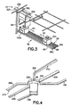
- Figs. 3 and 5 there is shown respectively a partial perspective view of a portion of transport branch 22A of the transport system section 12 and a portion of a conveyor run 56 of the transport system section 14, and another partial perspective view of a portion of conveyor run 56.
- the portions of transport branch 22A and conveyor run 56 are representative of the transport branches and conveyor runs of transport system sections 12, 14.
- Fig. 3 only one track 23A (see also Fig. 2 ) of the branch segment 22A is shown for example purposes.
- Fig. 3 only one track 23A (see also Fig. 2 ) of the branch segment 22A is shown for example purposes.
- Fig. 1 see also Fig.
- Conveyor run 56 is mounted with mounting system 64 (which will be described in greater detail below) to the overhead mounts 300 of the track 23A making up the interbay branch segment 22A.
- Conveyor runs 52, 54, and 58 are mounted in a similar manner from the overhead mounts of adjacent interbay/ intrabay transport branches.
- Conveyor run 56 generally comprises a rail system 60.
- the rail system 60 supports workpiece holding containers 151 and allows the containers to move freely along the length of the run 56.
- Conveyor run 56 also has a motor 62 for driving the containers 151 on rail system 60 back and forth (in the direction indicated by arrows X3, X4 in Fig. 3 ) along the rails.
- the motor 62 is a linear motor with an unlimited stroke.
- the rail system 60 in this embodiment has two outer runs 660, 66I and a central rail.
- the rail system of the conveyor runs may have any other suitable rail arrangement.
- the outer rails 660, 66I are similar but opposite hand. Accordingly, the outer rails 660, 66I will be described with specific reference to rail 66I.
- Rail 66I may have a general angle structural member 70, though any suitable structural shape member may be used.
- the angle 70 has horizontal and vertical flanges 70H, 70V.
- the angle 70 is oriented with the horizontal flange 70H on the bottom and the vertical flange 70V extending upwards.
- the horizontal flange 70H may define a support surface for the workpiece holding containers 151 placed on the conveyor run.
- the vertical flange 70V defines the outer edge 61E of the rail 66, and hence of the rail system.
- the vertical flange may also define a guide surface 66G of rail 66 containing the side of the container 151 for directional stability when the container 151 is moving along the rails 660, 66I in the directions indicated by arrows X3, X4 in Fig. 5 . Accordingly, the opposing guide surface 66G stably guide the container 151 when it moves on the rails 660, 66I.
- each rail 660, 66I may be provided with roller bearings or bushings 72 that are mounted to the rail to provide the rail with an enhanced sliding surface on which the container may slide over the rails.
- roller bearings 72 when seated on the conveyor run 56, the container 151 rests on roller bearings 72 and may thus move without substantial resistance over the rollers.
- the enhanced sliding surface of the rails may be provided by any other suitable means including for example ball bearings (mounted in one or both flanges) or a lubricious layer attached to the flanges of the rail member.
- Roller bearings 72 may be tapered for added directional stability when the container 151 is moving over the rollers in directions indicated by arrows X3, X4.
- linear motor 62 may be any suitable type of linear motor with an unlimited stroke capable of moving containers 151 on rails 660, 66I in directions X3, X4 to the ends of the conveyor run (see Fig. 2 ).
- the linear motor 62 is in general a solid state motor without moving parts.
- the linear motor 62 may be a brushed or brushless AC or DC linear motor, a linear induction motor, or linear stepper motor. Suitable linear motors are available from Baldor Motion Products or MagneMotion Inc.
- the linear motor 62 generally has two components, a primary or forcer component and a secondary, reaction or platen component.
- the forcer component 74 is in the center rail 68 of the conveyor run 56, and the reaction component 76 is integrated, as will be described in greater detail below, into the workpiece holding container 151.
- the reaction component may be mounted to the conveyor rails and the forcer component may be incorporated into the container.
- the center rail 68 may have a generally U-shaped structural member defining a groove 69.
- the forcer component 74 of the motor 62 is located in the groove.
- forcer 74 may be a coil assembly comprised of steel laminations and phase windings.
- the forcer 74 is connected by suitable wiring (not shown) to a power source (not shown) and controller C (see Fig. 2 ) that controls the traveling magnetic field generated by the forcer 74.
- the motor 62 may be a closed loop motor with suitable commutation devices 74C, such as Hall effect devices mounted for example on rail 68 and in communication with controller C.
- the commutation devices 74C serve as a position sensor, sensing the exact position of the container 151 on the conveyor run 56.
- rails 66I, 660, 68 of the rail system 60 may have a modular construction.
- rail 660 may include modules 6601, 6602 (only rail modules 6601, 6602 are shown in Fig. 5 for example purposes).
- the rail modules 6601, 6602 are joined at the intermediate joint 660I.
- the rail modules 6601, 6602 are provided with any suitable mating means, (e.g. interlocking facets, mechanical, fasteners) allowing the modules to be joined together end to end as shown in Fig. 5 .
- the center rail 68, and outer rail 66I have a similar modular construction.
- the rail modules similar to modules 6601, 6602 may be provided in any suitable length, such as a few feet, for ease of handling during installation.
- the rail modules may be joined together during installation to form the rails 660, 66I, 68 of the rail system of the conveyor run 56.
- rail modules similar to modules 6601, 6602 may be assembled during installation in the facility to form rail 66 from one end 56L (see Fig. 2 ) of run 56 to the other end 56R.
- the center rail 68, and other outer rail 66I may be similarly installed to form conveyor run 56.
- the rail modules, such as modules 6601, 6602 may otherwise be installed to modularly install the conveyor run 56.
- modules for all rails 66I, 660, 68 may be installed to form one or more conveyor run modules 56M1, 56M2 (see Fig. 2 ).
- the conveyor run 56 installation then proceeds module by module.
- Modules 56M1, 56M2 of conveyor run 56 are described above as being installed first for example purposes only, and in alternate embodiments the center modules of the conveyor run may be installed first.
- the conveyor modules 56M1, 56M2 are joined at intermediate run joints 56I. Once installed, each conveyor run module 56M1, 56M2 may become operational as soon as desired and before completion of the entire run 56. This is allowed in part by the use of the solid state motor 62 which unlike conventional conveyor systems does not employ a mechanical transmission that is coupled to all the drive rollers before the conveyor run may become operational.
- motor 62 is capable of precisely starting and stopping the container transported by the conveyor run 56 as will be seen further below.
- the linear motor 62 of section 14 is capable of operating with misalignment between modules of the center rail 68 commensurate with modular structural assembly tolerances under field conditions.
- a conventional mechanical conveyor drive system (such as illustrated in Fig. 1A ) is restricted to the much tighter mechanical tolerances of the drive.
- the drive rails for a conventional conveyor run must be fabricated in one piece offsite for substantially the entire length of the run, and then installed as one piece in the facility.
- the transport system section 14 has much greater flexibility in both installation and use during start up compared to conventional systems.
- the reaction component of platen 76 of the linear motor is incorporated into the workpiece holding container 151.
- the workpiece holding container 151 is depicted as a Front Opening Unified Pod. (FOUP) container, but can be any suitable container such as a SMIF pod or a bottom opening container.
- the FOUP container 151 has a container housing 154 (see Fig. 5 ) sized to hold a number of semiconductor workpieces such as 200 mm, 300 mm wafers, or flat panel displays or any other desired kind of workpieces.
- the housing 154 is capable of interfacing directly with the interface of processing tools P (see Fig. 2 ).
- the housing 154 may include engagement surfaces 156, such as detents or recesses to allow the hoist 206 (see Figs. 6A-6B ) of the transport vehicle 200 to capture and hold the container 151.
- the engagement surface 156 may be arranged to allow the capture arms 208 of the hoist 206 to pick the container from either sides 154R, 154F or front/back sides 154R, 154L (see Fig. 5 ).
- the hoist 206 of vehicle 200 may pick the container 151 regardless of the orientation of the container under the hoist.
- the container housing 154 may include an upper part 154U and a lower part 154L.
- Container door 155 which is removably latched to the housing, is shown covering the opening in the front 154F of the housing.
- the upper part 154U of the housing may be a one-piece molding made from plastic or any other suitable material capable of being used to hold semiconductor workpieces without contamination.
- the material for the housing is capable of being subjected to a full immersion bath during periodic cleaning of the container
- the lower part 154L of the housing is also a plastic molding. In the embodiment shown in Fig.
- the lower housing part 154L has a general flat shape forming the bottom of the container.
- the lower part 154L may be joined to the upper part 154U using any suitable process, such as chemical bonding, ultrasonic welding or others resulting in a substantially seamless interface between the lower and upper housing parts.
- the reaction component 76 of the linear motor 62 (disclosed in greater detail below) is molded within the lower part 154L.
- the lower housing part 154L has a lower surface 152, shown in Fig. 7A .
- the lower surface 152 has seating surfaces 158, 160 disposed in a biaxial arrangement on the lower surface.
- the seating surfaces 158, 160 are located around the perimeter of the lower surface 152, to allow the container to seat against the rollers 72 of rails 660 66I (see Fig. 6 ).
- the biaxial arrangement of the seating surfaces allows the container to be properly seated on the rails with either axis A, B oriented with the rails.
- Fig. 7A also shows an exemplary distribution of the reaction component 76 of linear motor 62 in this embodiment. As noted above, the reaction component 76 is molded in the lower container housing molding 154L.
- reaction component 76 is sealed within the lower housing part 154L. This eliminates seams between the reaction component and surrounding housing structure thereby eliminating areas where contaminants may collect. Further, by enclosing the reaction component 76 within the housing adverse interaction between the reaction component and cleaning bath is avoided.
- the reaction component 76 comprises, in this embodiment, reaction elements 162, 164, 166, 168 which are schematically illustrated in Fig. 7A .
- the reaction elements 162, 164, 166, 168 are also arranged biaxially on the container housing 154.
- the reaction elements may be permanent magnets or plates made from magnetic material capable of reacting with the magnetic fields generated by the forcer 74 to drive or thrust the containers along the rails 660, 66I.
- Reaction elements 162, 164 are aligned along axis B in order to provide drive forces (in cooperation with forcer 74 or other forcers aligned with axis B) in the axis B direction.
- Reaction elements 166, 168 are arranged to provide drive forces in a similar manner along the A axis.
- the container 151 is shown in Fig. 5 placed on the rails 660, 66I in an orientation where axis A (see also Fig. 7 ) is aligned with forcer 74.
- the container 151 may be placed on the rails in an orientation rotated 90° from that shown in Fig. 5 .
- the container 151 axis B would be aligned with the forcer 74.
- the biaxial drive configuration effectively reduces the time used to place or pick the container from the conveyor run 56 in comparison to conventional transport systems (i.e. smaller rotation to find usable drive axis compared to conventional systems).
- Fig. 7B is a bottom perspective view of the lower housing part 154L' in accordance with another embodiment.
- the lower housing part 154L' in this embodiment is generally similar to lower housing part 154L described before and shown in Figs. 7-7A , and similar features are similarly numbered.
- Lower housing part 154L' has recesses 167', 169' formed therein for mounting the reaction component 76' to the container housing.
- two recesses, 167', 169' are shown for example purposes, generally aligned with axis of symmetry A'.
- the recess 1167', 169' are formed in the bottom surface 152'. This leaves the bottom surface of the reaction component elements exposed when installed.
- the recesses may be formed into the upper surface 152U' of the lower housing part so that when installed the reaction component elements are not exposed on the outer surface of the housing.
- the recesses, 169', 167' are blind as shown and do not extend through the lower housing part, though in alternate embodiments, apertures through the lower part may be used in place of the recesses.
- the recesses 169', 167' may be formed during molding of the lower housing part 154L' or may be machined into the lower housing part after fabrication of the housing part.
- the recesses 169', 167' are substantially conformal to the reaction component elements (only reaction component element 168'is shown for example purposes) and are sufficiently deep so that when positioned into the corresponding recesses, the bottom surface of the reaction component elements is substantially flush or somewhat inwardly displaced from the bottom surface 152' of the housing.
- the reaction component elements 168' may be mounted to the lower housing part using any suitable bonding or fastening means including mechanical fasteners. Suitable seals (not shown) may be used to eliminate gaps/crevices that may collect contaminants.
- the bottom of the housing may not include recesses or pockets, and the reaction component elements may be surface mounted to the bottom.
- the reaction component elements may be assembled in a frame, and the frame may be mounted to the bottom of the container housing, or positioned into a recess in the housing. In this case, the reaction component may be replaceable.
- FIG. 7C there is shown another bottom perspective view of the lower part 154L" of the container housing in accordance with yet another embodiment.
- the lower housing part 154L is generally similar to the housing part 154L described before and shown in Fig. 7 . Similar features are similarly numbered.
- the reaction component 76" is mounted in a turn table assembly 170".
- the turn table assembly 170" may be mechanically mounted or otherwise connected to the bottom 152" of the housing lower part.
- the assembly 170" may be surface mounted or may be located in a recess 167" as shown in Fig. 7C . If desired, the turn table assembly 170" may be replaceable.
- the turntable 170" may have any suitable configuration, but in general it includes a base 172" and pivot section 174".
- the base 172" provides the interface for attaching the turn table 170" to the housing part 154L".
- the pivot section 174" is movably mounted to the base section 172" by any suitable means to allow the pivot section 174" to rotate relative to the base section in the direction indicated by arrow R.
- the react ion component 76 schematically shown in Fig. 7C having representative elements 166", 168" is attached to the pivot section 174".
- the orientation of the reaction component 76" may be changed as desired. For instance, rotating the turntable may move elements initially oriented along axis A" to any desired orientation such as alignment with axis B".
- the turntable may be provided with appropriate interlocks (not shown) to fix the turntable in any orientation.
- the interlocks may be activated with the forcer 74 of the linear motor.
- the forcer of the linear motor may also be used in cooperation with reaction component 76" to effect rotation of the turntable.
- the controller C controls the traveling magnetic field generated by forcer 74 to move the container as desired.
- the controller C registers the position of the container 151 during movement on the conveyor run 56 via for example, the commutation sensors 74C.
- the controller may register the location of the container by detecting the direct commutation in the motor.
- the controller C may move container 151 along the conveyor run 56, in either direction indicated by arrows X3, X4 in Fig. 3 at any desired speed and to any desired position.
- the controller C is capable of accurately placing the container 151 at any desired position along the run 56.
- controller C is capable of controlling forcer 74 to drive any desired number of containers along the conveyor run 56. Also the controller is capable of controlling the forcer 74 to move containers on the same conveyor run in opposite directions substantially at the same time. For example, as seen in Fig. 3 , container 151 may be moved in direction X3 by the linear motor, while container 151A is being moved in direction X4.
- the transport vehicle 200 may be at a given position ⁇ on a track 22A of transport system section 12.
- the transport vehicle may be at location ⁇ having just released a container on conveyor run 56.
- Position ⁇ can be any position along track 22A.
- the vehicle hoist is shown in Figs. 6A-6B as being in the retracted position, though the hoist may be in its extended position (not shown) in which it can pick/release containers 151 from run 56.
- the hoist 208 may be in the orientation shown in Fig. 6B , rotated 90° from that shown in Fig. 6A .
- the gripper arms of the hoist are disposed astride the rails of the run 56.
- the controller C controls the linear motor to bring a desired container 151 along run 56.
- the controller registers the position ⁇ of the transport vehicle 200 on track 22A and matches the position O of the container 151 so that the container is aligned, in this case under vehicle 200.
- Controller C controls position O on run 56 so that the vehicle hoist 208 may be merely extended to pick container 151 without further repositioning of the vehicle 200 on track 22A.
- conveyor runs for example runs 52, 56 of the transport system section 14, may be provided with shunts or run buffer sections 52B, 56B.
- the run buffer sections 52B, 56B are depicted schematically in Fig. 2 , on one side of the conveyor runs, but may be located on either side of the runs.
- Fig. 5 shows a portion of a representative buffer section 56B on run 56.
- the buffer section has a support platform 90, which for example may be made from one or more rails 92.
- the support platform 90 intersects at least one of the conveyor run rails 660.
- the vertical flange 66V of the conveyor run rails 660 may be removed locally in way of platform 90.
- the support platform 90 may include omnidirectional supports such as ball bearings 93 (see Fig. 5 ) allowing the container 151 to move freely in any desired direction over the supports.
- the buffer section 56B may also include a suitable linear forcer component 94 capable of cooperating with the reaction elements 162, 164, 166, 168 on the container 151 (see Fig. 7 ) to move the container in the directions indicated by arrows X5, X6 in Fig. 5 into and out of the buffer section 56B.
- the container 151 can be moved from the conveyor run 56 to the buffer section 56B and vice versa without reorienting the container. For example, in the orientation shown in Fig.
- the container 151 is moved in direction X4 until substantially aligned with buffer section 56B.
- the reaction elements 164, 162 arranged to operate along axis B of the container are capable of cooperating with the forcer 94.
- the controller C activates forcer 94 to move container 151 in direction X5 into the buffer section 56B.
- forcer 94 is operated to move the container in direction X6 onto the rails 660, 66I.
- the container 151 can then be moved almost instantaneously thereafter in any desired direction along conveyor run 56.
- any suitable type of junction device such as for example, using a turntable, may be used to di rect the container from the conveyor run into the buffer section.
- the switching system enabling container transfer between conveyor run and buffer section is equally applicable to effecting transfer between any joining conveyor runs (see Fig. 2 ).
- the buffer section 56B may be sized to hold as many containers 151 as desired.
- a single linear forcer component 94 may be provided with a pair of support rails 92.
- additional linear forcer rails 94L and support rails 92L may be added in a general grid pattern as shown in Fig. 5 .
- the pattern of outwardly extending rails 92, 94 and lateral extending rails 92L, 94L form the grid pattern which enables a container to move two dimensionally (in the directions indicated by arrows X5, X6, X7) to any location in the buffer section 56B.
- a single set of outward rails 92, 94 and a single set of lateral rails 92L, 94L is shown for example purposes.
- the rail pattern shown can be repeated as desired to provide a buffer section of any desired size.
- mounting system 64 may include any suitable structural members to support the rails 660, 66I, 68 of the conveyor run 56 substantially under the track 23A of the corresponding interbay or intrabay transport branch. This allows the transport vehicles 200 on at least some portion of the tracks of the interbay or intrabay branches to pick or place containers 151 directly on the conveyor runs. Unlike conventional systems, the containers 151 an be placed by transport vehicles 200 on the conveyor runs at any time, and be moving on the conveyor runs immediately thereafter. Accordingly, seamless integration between the transport system section 12 and transport system section 14 (as no time is lost to coordinate between transport vehicles 200 on system section 12 on transport panels used in conventional conveyor systems). This in turn increases workpiece traveling density of the automated material handling system 10 and reliability (a defective container is readily removed from the system, and unlike a palletized system the impact is limited to only to that container without any loss in system transport capacity).
Landscapes
- Engineering & Computer Science (AREA)
- Mechanical Engineering (AREA)
- Container, Conveyance, Adherence, Positioning, Of Wafer (AREA)
- Warehouses Or Storage Devices (AREA)
- Non-Mechanical Conveyors (AREA)
Abstract
Description
- The present invention relates to material handling systems and, more particularly, to a automated material handling systems for transporting semiconductor workpiece holding canisters or containers in processing facilities.
- Consumers continue to manifest a desire for ever more sophisticated electronic and electrical devices that are smaller in size and cheaper than current models. Manufacturers of microelectronic devices are thus under increased pressure to provide more capabilities to the devices while at the same time reducing the cost of the devices. The potential for reduction in cost of the materials used in fabricating the microelectronic devices, or in the cost related to actual fabrication of the devices is limited. However, significant cost reductions may be achieved by increasing the efficiency of the whole manufacturing process. Referring to
Fig. 1 , there is shown a perspective view of a representative conventional semiconductor fabrication facility 1. The fabrication or fab facility 1 has a number offab bays 2 arranged in the facility in a desired array. Thefab bays 2 include vacuum andatmospheric processing tools 3, 4 where the semiconductor devices are manufactured. The fab facility 1 also has an automated material handling system installed therein for transporting the semiconductor material to and from the semiconductor devices. The conventional material handling system in the fab facility shown inFig. 1 , generally includes stockers 5,interbay transport system 6, andintrabay transport system 7. In this arrangement, the stockers 5, used to store the semiconductor devices between various processing evolutions, are located adjacent the opening of thefab bays 2 on a common passage linking thefab bays 2. Theinterbay transport system 6 is installed in the common passage and connects the stockers 5. This allows semiconductor devices to be transported, by suitable vehicles traveling on the interbay transport system 5 between stockers 5. Theintrabay transport system 7, as seen inFig. 1 , hassections 7A-7B disposed in the fab bays linking the stockers 5 adjacent the opening of a given bay to theprocessing tools 3, 4 in that bay. Thus, semiconductor devices can be transported between the stockers 5 of a bay and the processing tools in that bay with suitable vehicles traveling on thecorresponding section 7A-7F of the intrabay transport system. - As can be realized from
Fig. 1 , the automated material handling system is one of the significant factors in the efficient fabrication process in the fab facility. A significant amount of time is consumed transporting the semiconductor material with the material handling system, to and from the processing tools. Indeed, the larger the processing facility, in order to achieve economies of scale, the greater the time consumed transporting semiconductor material with the material handling system to and from processing tools within the facility. Thus, the size of the facility itself becomes limited by the speed and efficiency with which the material handling system is capable of delivering semiconductor material to the processing tools for processing, and removing the processed workpieces to stockers for ultimate completion and shipping. Attempts to increase efficiency by reducing transport time have been made, and have achieved success in cases. For example, the Aeroloader™ automated material handling system from Brooks Automation, Inc. employs overhead transport vehicles or shuttles on overhead tracks to transport semiconductor workpiece container over the interface of the processing tools. Further increases in speed, and hence efficiency, at which semiconductor workpieces are transported around the facility have been sought. Some conventional material handling systems, have used a conveyor or mass transport system alone or as part of the system.Fig. 1A is a partial perspective view of a portion of a conventional conveyor system such as for example disclosed in international patent publicationWO 03/038,869 Fig. 1A is conventional container such as a conventional FOUP or SMIF container. As noted before,Fig. 1A shows a portion of a conveyor track CT of the conventional system. The track CT inFig. 1A may be representative of one or more of thetracks 7A-7F of the system inFig. 1 . The conventional conveyor track CT inFig. 1A comprises a pair of rails R1, GR. The conventional conveyor system uses a pallet P as shown to support the conventional container F on the conveyor track CT. The pallet P has a support area on which the container F may be seated. The pallet P may also have runners P1, P2 to allow the pallet P to ride over the conveyor rails R1, GR. One runner P1 may be flat, defining a rolling surface for rollers RR in rail R1. The other runner P2, may have a guide slot, or guide key mated to the rail GR to guide the pallet P along the rails during transport. Rail R1 of the conventional conveyor track shown inFig. 1A may include powered rollers RR to drive the pallet P on the rails. The rollers RR are coupled by a suitable transmission, such as an endless belt, to a drive motor capable of turning the rollers. To move the pallet P, and hence the container seated thereon, in the conventional system shown inFig. 1A , the motor rotates the rollers RR and the frictional contact between rollers and pallet runner P1 causes the pallet to move. The other runner P2 of the pallet P, slidably mated to rail GR, guides the pallet as it is moved down the rails maintaining alignment between the pallet runner P1 and drive rollers RR. As can be realized fromFig. 1A , alignment between the pallet runner, and hence between rail GR, and the contact line of the line of rollers RR in rail R1 should be highly accurate in the conventional mechanical driven conveyor track to allow the pallet to be driven true to the track. The conventional system is not misalignment tolerant. Misalignment, may generate a force on the pallet orthogonal to the track, resulting in undesired friction, possible binding, between runner P2 and rail GR and in increased potential for particulate contamination on the container. In addition, alignment between rollers RR on rail R1 should be precise to avoid a contact/drive line between rollers and runner P1 that is angled relative to the track. Accordingly, precise alignment between the rails R1 and GR is achieved in the conventional system by fabricating extended sections of track CT in a jig prior to installation in the processing facility. However, such extended sections of track are difficult and time consuming to install in the processing facility. An additional shortfall of the conventional conveyor system is its poor ability to position a container at a desired location along the track. The conventional conveyor system may include a position locating system for the pallet. The conventional locating system includes providing one of the rails R1 with sensors (e.g. electronic, electro-optical) capable of detecting a feature on the pallet P when the pallet is in a predetermined area relative to the sensors. The sensors are equally distributed along the rails. The rollers RR, alone or in combination with the drive motors may have an encoder identifying the rotation of the rollers. The position of the pallet P at any time is established using the combination of data from the rail sensors and rollers. As can be realized, the conventional locating system is subject to inaccuracies because of possible slippage between rollers RR and pallet during acceleration/deceleration, as well as that locating the pallet between sensors is dependent merely on counting roller revolutions. The combination of the limitations of frictional drive and the conventional position location system deprive the conventional conveyor track of effective fine position control. A further problem of the convention conveyor system is that movement of semiconductor material containers on the transport system is dependent on availability of transport pallets. The present invention provides the desired efficiency for the material handling system, as will be described in greater detail below. - In this connection,
US patent 6,468,021 B1 andUS patent 5,443,346 already show semiconductor work piece processing systems comprising at least one processing tool for processing semiconductor work pieces; a container for holding at least one semiconductor work piece therein for transport to and from the processing tool; a first transport section connecting to the processing tool for transporting the container to and from the processing tool; and a second transport section connected to the first transport section for transporting the container to and from the first transport section; wherein the first transport section is a vehicle based section having a transport vehicle capable of holding the container and moving along a first track of the first transport section, and the second transport section is a conveyor section and has a second track with at last one support element of the second track adapted to interface with the container for movably supporting the container from the second track and allowing the container to move relative to the first track, and wherein the second transport section has a motor connected to the second track for aligning the container on the second track with the transport vehicle on the first track. - The system of
US 6,468,021 B1 , however, only uses the first transport section to transport the containers arriving on the conveyor based transport for small distances vertically. In this citation, all horizontal transporting jobs are made by the conveyor system. The vehicle based system only serves to transport the containers vertically to their final destination at a processing station. - In
US 5,443,346 , the vehicle based system is also arranged orthogonally to the conveyor based system and also only serves to transport the containers arriving on the conveyor system for "the last meter" to the processing stations. - According to the invention, this object is achieved by the features of claim 1. The subclaims contain preferred features for further developing this system.
- The foregoing aspects and other features of the present invention are explained in the following description, taken in connection with the accompanying drawings, wherein:
-
Fig. 1 is a schematic perspective view of a semiconductor fabrication facility with a conventional material handling system; -
Fig. 1A is a partial respective view of a portion of the conventional handling system inFig. 1 ; -
Fig. 2 is a schematic plan view of an automated material handling system incorporating features of the present invention and processing tools P in a processing facility; -
Fig. 3 is a partial perspective view of a portion of the automated material handling system inFig. 1 , showing track sections, a transport vehicle and semiconductor workpiece containers of the automated material handling system; -
Fig. 4 is another partial perspective view of a portion of one of the track sections inFig. 3 and a transport vehicle of the automated material handling system; -
Fig. 5 is still another partial perspective view of a portion of another one of the track sections inFig. 3 and a semiconductor workpiece container of the automated material handling system; -
Figs. 6A-6B are respectively front and side elevation views of the track sections inFig. 3 , a transport vehicle and semiconductor workpiece container of the automated material handling system; -
Fig. 7 is an exploded perspective view of the workpiece container andFig. 7A is a bottom view of the workpiece container; and -
Figs. 7B-7C respectively are bottom perspective views of a lower part of the workpiece container housing in accordance with other embodiments. - Referring to
Fig. 2 , there is shown a schematic plan view of an automatedmaterial handling system 10 incorporating features of the present invention and processing tools P in a processing facility. Although the present invention will be described with reference to the single embodiment shown in the drawings, it should be understood that the present invention can be embodied in many alternate forms of embodiments. In addition, any suitable size, shape or type of elements or materials could be used. - The automated
material handling system 10 generally includes a firsttransport system section 12 and a secondtransport system section 14. Thetransport system sections material handling system 10 are generally arranged to allow transportation of semiconductor workpieces, such as for example, 200 mm wafers, 300 mm wafers, flat display panels and similar such items, to and from processing tools P in the processing facility. The processing tools P, and the facility are generally similar to the facility 1 and tools 4 described before and shown inFig. 1 . The configuration of the automatedmaterial handling system 10 shown inFig. 2 is a representative configuration, and the automatedmaterial handling system 10 may be disposed in any suitable configuration to accommodate any desired layout of process tools in a processing facility. Onetransport system section 12 of the automatedmaterial handling system 10 is a vehicle based system. Thetransport system section 12 comprises tracks 16 and transport vehicles 200 (see alsoFig. 4 ). Thetransport vehicles 200, as will be described in greater detail below, are capable of holding a semiconductor workpiece container (not shown inFig. 1 ) and travel along the tracks 16 oftransport section 12. Thetransport vehicles 200 thus move the workpiece containers along tracks 16 between processing tools, or between processing tools and stockers (not shown) similar to stockers 5 shown inFig. 1 . The othertransport system section 14 of the automatedmaterial handling system 10 is not a vehicle based transport system.Transport system section 14 is a conveyor based or high speed (relative to a vehicle based system) mass delivery system.Transport system section 14 comprises a track or run 18 capable of directly conveying, without the use of intermediate transport vehicles, semiconductor workpiece containers at high speed as will also be described in greater detail below. Thetrack 18, as shown schematically inFig. 2 , may extend along at least some portions of track 16 of the othertransport system section 12. Thetrack 18 oftransport system section 14 may also span between different portions of track 16 oftransport system section 12. The semiconductor workpiece containers may be transferred as desired between thetrack 18 ofsection 14 and transport vehicles 200 (seeFig. 3 ) on track 16 ofsection 12. The automatedmaterial handling system 10 may transport semiconductor workpiece containers using any desired combination of the first and secondtransport system sections Fig. 2 , a suitable controller C is connected to the first and secondtransport system sections transport system section 14 may also provide a distributed storage or buffer for the automated material handling system as will be described in greater detail below. - In greater detail now, and with reference to
Figs. 3 and 4 , thefirst system section 12 of the automatedmaterial handling system 10 generally includes track 16 andtransport vehicles 200, as noted above.System section 12 may be generally similar to the automated material handling system described inUS-A-2004181929 . As seen inFig. 2 , the track 16 ofsystem section 12 may be arranged intointerbay intrabay intrabay branches Fig. 1 ) of the fab facility. Theinterbay branches more intrabay branches Fig. 2 , there are threeintrabay branches interbay portions interbay branches intrabay branches - The
interbay transport branches Fig. 3 are substantially parallel to each other, though in alternate embodiments different interbay branches may not be parallel. Indeed, interbay transport branches may not connect all fab bays and may have any shape. The present invention encompasses any interbay transport system arranged in any desired manner to connect any desired number of fab bays. In this embodiment, theinterbay transport branches central portions 20. Theinterbay transport branch 20 may be made up of interbay transport segments orelements 20A-20B. In the embodiment shown inFig. 2 , there are twosegments 20A-20B for example purposes only, and in alternate embodiments the interbay transport branch may have any desired number of segments. Eachsegment 20A-20B is of sufficient length to span between two adjoining fab bays and specifically between adjacent portions of the intrabay transport system. For example,segment 20A spans between adjoiningintrabay port ions - As seen in
Fig. 2 , eachsegment 20A-20B may havemultiple transport paths 19A-21A, 19B-21B, 19C-21C provided by any suitable table means (as will be described below) for transport vehicles (not shown), allowing the vehicles to traverse the segment. The transport paths of each segment are arranged to allow substantially simultaneous bi-directional travel of the transport vehicles on the segment (in directions indicated by arrows X1, X2). In this embodiment, eachsegment 20A-20B may have twotransport paths 19A-21A, 19B-21B extending between the ends of the segment. One path, such as for example 19A, 19B, may be used by transport vehicles to travel in one direction (indicated by arrow X1) and the other path, 21A-21B, may be used for travel in the opposite direction (indicated by arrow X2). The travel paths may be dedicated to a given direction of travel or the direction of travel may be switched as desired according to a transport algorithm to suit transport loading conditions. For example, in the non-dedicated case,transport path 19A ofsegment 20A may at first be used for vehicles traveling in the direction indicated by arrow X1 inFig. 2 . At that time,path 21A provides for travel in direction X2. However, if at some later time it is anticipated that some number of transport vehicles are situated in the facility and are going to a location where it would be more efficient to move overpath 19A in direction X2, then the travel direction forpath 19A may be changed to direction X2,path 21A then becoming used for X1 travel. It is noted, that in this embodiment travel direction need not be the same forsimilar paths 19A-19B, 21A-21C of each segment. For example,transport path 21A may be used for travel direction X2, buttransport path 21B may be used for the opposite travel direction X1. This ability is provided by theinterbay transport segments 22A-22C in this embodiment because as seen inFig. 2 , the corresponding transport paths of each segment converge towards each other at opposite ends 32A-32B and 32C-32D of eachsegment 20A-20B. As seen inFig. 2 , eachsegment 20A-20B has ajunction Fig. 2 segment 20A has ajunction 34 at oneend 32A and anotherjunction 36 at theopposite end 32B. Therespective travel paths 19A-19B, 21A-21B of eachsegment 20A-20B substantially intersect at each correspondingjunction Fig. 2 , thejunctions 36 between segments are used to connect the adjoining segments to each other.Junction 36 connects adjoining ends 32B-32C ofsegments Junction 36 may further allow ties between same or different transport paths of the connected segments. For example,junction 36 may be used to tietransport path 19A ofsegment 20A to thetransport path 21B ofsegment 20B thereby allowing transport vehicles to cross betweenpaths - In this embodiment, the
intrabay branches interbay branches Fig. 2 as noted before, the intrabay transport is also made up of three branches for example purposes. Each branch may comprise a single transport segment or element, or may comprise a number of interlinked segments. In the embodiment shown inFig. 2 , each branch has twosegments 26A-26B, 28A-28B, 30A-30B. Eachbranch segment 26A-30B may extend within a single fab bay or may be further branched to other fab bays. Theintrabay transport segments 26A-26B, 28A-28B and 30A-30B are generally similar to each other and hence are schematically illustrated the same inFig. 2 . Each of thesegments 26A-26B, 28A-28B, 30A-30B has multiple transport paths, similar to theinterbay segments paths segment 26A, may converge towards each other at opposite ends 40A, 42A of the segment. At thenear end 40A the transport paths terminate injunction 34. As noted before,junction 34 is the terminus ofinterbay transport paths interbay transport segment 20A. Thus, theinterbay transport paths intrabay transport paths intrabay transport segment 26A. In this embodiment, the transport paths, such as for example,paths segment 26A, terminate in ajunction 44 at thefar end 42A. Junction' 44 ties in the transport paths to interbaytransport segment 22A. In a similar manner, junctions may tie the transport paths ofintrabay segments 26B-30B to the outerinterbay transport segments 24A-24B. In alternate embodiments, the intrabay transport segments may have any other suitable arrangement. - The interbay and intrabay branches of
first transport system 12 are shown inFig. 2 and have been described above in the context of a representative configuration that can be provided by any number of suitable types of material handling systems.Fig. 4 is a partial perspective view of a representative portion of an interbay or intrabay transport branch showing one suitable example of the types of handling system materials that may be used for the automatedmaterial handling system 10. As seen inFig. 4 , theinterbay transport segments 20A-20B (only parts ofsegments Fig. 4 for example purposes) are formed using an overhead rail system such as the Aeroloader™ system available from Brooks Automation, Inc. In this case, eachtransport path 19A-19B, 21A-21B is provided by a corresponding rail or track. The tracks may be mounted to the fab facility overhead. Referring also toFigs. 6A-6B , there are shown respectively partial front and side elevation views oftracks 20A and atransport vehicle 200. -
Fig. 4 shows athird track Fig. 2 for clarity) which provides a high speed or "fly-through" transport path for each segment. As described before, the tracks converge at thejunction 36 between the adjoining segments. In the embodiment shown inFig. 4 junction 32 includes aturntable 202, though any suitable track switching device may be used. In this case the turntable has three positions to tie the diametrically opposed track ends of therespective transport paths 21A-19B, 23A-23B, 19A-21B. When the turntable is positioned in one of these positions, atransport vehicle 200 may cross between diametrically opposed track ends without moving the turntable. Otherwise, the transport vehicle may be positioned onto the turntable, and the turntable may be rotated as desired to allow the transport vehicle to move from anytrack other track - Automated overhead transport vehicles 200 (only one is shown in
Figs. 4 and 6A-6B for example) such as the Aeroloader™ system shuttles are mounted on one of the tracks. Thetransport vehicle 200 may be sell propelled to autonomously travel on the corresponding rail forming each of the travel paths. Each vehicle travels on the desired transport paths according to a transport algorithm which may be preprogrammed into vehicle memory (not shown) or loaded from a central processor (not shown) operating the automated material handling system. In this embodiment, though any other suitable type of transport vehicle may be used. Thetransport vehicle 200 may have a transport section 204 (seeFigs. 6A-6B ) and apayload section 206. The transport section 240 includes suitable wheels/rollers (not shown) to support and move the vehicle on the track. The transport section may also include a power source and motor for driving the vehicle along the track. Thepayload section 206 is mounted or otherwise supported from the transport section, and in this embodiment is suspended below the transport section (seeFigs. 6A-6B ). Thepayload section 206 may include a hoist 208, in this embodiment schematically depicted as having gripper arms, capable of capturing and raising/lowering aworkpiece holding container 151.Figs. 6A-6B show a representativeworkpiece storage container 151 that may be used with the handling system 10 (and which will be described in greater detail below) located in a position where the hoist 208 of the transport vehicle is capable of engaging thecontainer 151. Thestorage container 151 may be in a storage area (not shown), such as a uniformly distributed storage area, under a track of any desired interbay or intrabay transport segment (representative segment 22A is shown for example purposes), or may be on the interface of a processing tool P (seeFig. 2 ) located below the track. As seen inFig. 2 , the tracks of the interbay and intrabay branches may be located over the tool interface of the processing tools P. Accordingly,transport vehicle 200 is capable of delivering and picking up workpiece container directly from the processing tools P. - Referring again to
Fig. 2 , thetransport system section 14, as noted before, is a conveyor based system, and unliketransport system section 12, does not use transport vehicles for holding and transporting the workpiece holding containers. Rather,transport system section 14 has a conveyor or mass delivery system arranged in conveyor runs, as will be described in greater detail below, that effect direct transport of the workpiece holding containers along the conveyor runs. As will also be described in greater detail below, the workpiece holding containers may be placed directly onto the conveyor runs, and are transported along the runs without using a transport vehicle or carriage interface between the holding container and run. As seen inFig. 2 , in this embodiment thetransport system section 14 has four runs 52-58. In this embodiment, the conveyor runs 52-58 are located around the perimeter of thetransport system section 12. In alternate embodiments, the conveyor runs may be arranged in any suitable configuration. In this embodiment, two conveyor runs 52, 54 extend alongsideintrabay transport branches interbay transport branches interbay branches intrabay branches Fig. 2 , each conveyor run 52-58 is proximate to a track of a interbay or intrabay transport branch. In this embodiment, each conveyor run 52-58 is substantially parallel with a corresponding interbay orintrabay transport branch conveyor run 52 isproximate track intrabay branch 26 for substantially the length ofbranch 26. Conveyor runs 54-58 are similarly positioned relative to corresponding transport branches. Although the conveyor branches 52-58 are shown inFig. 2 positioned proximate the outermost track of the respective interbay/intrabay branches, in alternate embodiments the conveyor runs may be proximate any suitable track of any desired interbay/intrabay transport branches. In other alternate embodiments, the conveyor runs may extend along any desired length of a interbay/intrabay transport branch. In still other alternate embodiments, the transport system section may have conveyor runs that are not located alongside an interbay/intrabay transport branch, such as for example conveyor runs effecting short circuits within the transport system section. As seen inFig. 2 , the conveyor runs 52-58, may each be interconnected at the ends to intersecting conveyor runs by a suitable junction device allowing a workpiece holding container to transit directly between runs. For example, oneend 52T ofconveyor run 52 is connected byjunction 61A to end 58R ofconveyor run 58. Theother end 52B ofconveyor run 52 is connected byjunction 61B to end 56R ofconveyor run 56. The other conveyor runs oftransport system section 14 may be similarly interconnected. As can be seen fromFig. 2 , the conveyor runs 52-58 ofsection 14 form a circuit enabling high speed transport of workpiece holding containers from any point of the adjoiningtransport system section 12 to any other desired point ofsection 12. This is highly advantageous compared to conventional transport systems. - The
transport system section 14 of automatedmaterial handling system 10, is shown inFig. 2 , and described above in the context of a representative configuration that can be provided by any number of suitable types of conveyor systems. Referring now also toFigs. 3 and5 , there is shown respectively a partial perspective view of a portion oftransport branch 22A of thetransport system section 12 and a portion of aconveyor run 56 of thetransport system section 14, and another partial perspective view of a portion ofconveyor run 56. The portions oftransport branch 22A andconveyor run 56 are representative of the transport branches and conveyor runs oftransport system sections Fig. 3 , only onetrack 23A (see alsoFig. 2 ) of thebranch segment 22A is shown for example purposes. As seen inFig. 3 , theconveyor run 56 is mounted with mounting system 64 (which will be described in greater detail below) to the overhead mounts 300 of thetrack 23A making up theinterbay branch segment 22A. Conveyor runs 52, 54, and 58 are mounted in a similar manner from the overhead mounts of adjacent interbay/ intrabay transport branches.Conveyor run 56 generally comprises arail system 60. Therail system 60 supports workpiece holdingcontainers 151 and allows the containers to move freely along the length of therun 56.Conveyor run 56 also has amotor 62 for driving thecontainers 151 onrail system 60 back and forth (in the direction indicated by arrows X3, X4 inFig. 3 ) along the rails. In this embodiment, themotor 62 is a linear motor with an unlimited stroke. As seen best inFig. 5 , therail system 60 in this embodiment has twoouter runs 660, 66I and a central rail. In alternate embodiments, the rail system of the conveyor runs may have any other suitable rail arrangement. Theouter rails 660, 66I are similar but opposite hand. Accordingly, theouter rails 660, 66I will be described with specific reference to rail 66I. Rail 66I may have a general anglestructural member 70, though any suitable structural shape member may be used. Theangle 70 has horizontal andvertical flanges angle 70 is oriented with thehorizontal flange 70H on the bottom and thevertical flange 70V extending upwards. Thehorizontal flange 70H may define a support surface for theworkpiece holding containers 151 placed on the conveyor run. Thevertical flange 70V defines the outer edge 61E of the rail 66, and hence of the rail system. The vertical flange may also define aguide surface 66G of rail 66 containing the side of thecontainer 151 for directional stability when thecontainer 151 is moving along therails 660, 66I in the directions indicated by arrows X3, X4 inFig. 5 . Accordingly, the opposingguide surface 66G stably guide thecontainer 151 when it moves on therails 660, 66I. As seen inFig. 5 , eachrail 660, 66I may be provided with roller bearings orbushings 72 that are mounted to the rail to provide the rail with an enhanced sliding surface on which the container may slide over the rails. By way of example, when seated on theconveyor run 56, thecontainer 151 rests onroller bearings 72 and may thus move without substantial resistance over the rollers. In alternate embodiment, the enhanced sliding surface of the rails may be provided by any other suitable means including for example ball bearings (mounted in one or both flanges) or a lubricious layer attached to the flanges of the rail member.Roller bearings 72 may be tapered for added directional stability when thecontainer 151 is moving over the rollers in directions indicated by arrows X3, X4. -
Center rail 68 ofrail system 60 forms part of thelinear motor 62 of theconveyor run 56. As noted before,linear motor 62 may be any suitable type of linear motor with an unlimited stroke capable of movingcontainers 151 onrails 660, 66I in directions X3, X4 to the ends of the conveyor run (seeFig. 2 ). Thelinear motor 62 is in general a solid state motor without moving parts. For example, thelinear motor 62 may be a brushed or brushless AC or DC linear motor, a linear induction motor, or linear stepper motor. Suitable linear motors are available from Baldor Motion Products or MagneMotion Inc. Thelinear motor 62 generally has two components, a primary or forcer component and a secondary, reaction or platen component. In this embodiment, theforcer component 74 is in thecenter rail 68 of theconveyor run 56, and thereaction component 76 is integrated, as will be described in greater detail below, into theworkpiece holding container 151. In alternate embodiments, the reaction component may be mounted to the conveyor rails and the forcer component may be incorporated into the container. By way of example, if a linear induction motor is used forlinear motor 62 in the embodiment shown inFigs. 3 and5 , thecenter rail 68 may have a generally U-shaped structural member defining agroove 69. Theforcer component 74 of themotor 62 is located in the groove. In the case of a linear induction motor,forcer 74 may be a coil assembly comprised of steel laminations and phase windings. Theforcer 74 is connected by suitable wiring (not shown) to a power source (not shown) and controller C (seeFig. 2 ) that controls the traveling magnetic field generated by theforcer 74. Themotor 62 may be a closed loop motor withsuitable commutation devices 74C, such as Hall effect devices mounted for example onrail 68 and in communication with controller C. As will be described further below, thecommutation devices 74C serve as a position sensor, sensing the exact position of thecontainer 151 on theconveyor run 56. - As seen in
Fig. 5 , therails rail system 60 may have a modular construction. For example,rail 660 may includemodules 6601, 6602 (onlyrail modules Fig. 5 for example purposes). Therail modules rail modules Fig. 5 . Thecenter rail 68, and outer rail 66I have a similar modular construction. The rail modules similar tomodules rails conveyor run 56. By way of example, rail modules similar tomodules end 56L (seeFig. 2 ) ofrun 56 to theother end 56R. Thecenter rail 68, and other outer rail 66I may be similarly installed to formconveyor run 56. The rail modules, such asmodules conveyor run 56. For example, modules for allrails Fig. 2 ). Theconveyor run 56 installation then proceeds module by module. Modules 56M1, 56M2 ofconveyor run 56 are described above as being installed first for example purposes only, and in alternate embodiments the center modules of the conveyor run may be installed first. The conveyor modules 56M1, 56M2 are joined at intermediate run joints 56I. Once installed, each conveyor run module 56M1, 56M2 may become operational as soon as desired and before completion of theentire run 56. This is allowed in part by the use of thesolid state motor 62 which unlike conventional conveyor systems does not employ a mechanical transmission that is coupled to all the drive rollers before the conveyor run may become operational. Further, unlike conventional systems,motor 62 is capable of precisely starting and stopping the container transported by theconveyor run 56 as will be seen further below. Yet another advantage arising fromtransport system section 14 using a solid state motor, similar tolinear motor 62, is that the solid state motor by its very nature can readily accommodate, without noticeable performance degradation, misalignment between rail modules. Thelinear motor 62 ofsection 14 is capable of operating with misalignment between modules of thecenter rail 68 commensurate with modular structural assembly tolerances under field conditions. In marked contrast, a conventional mechanical conveyor drive system (such as illustrated inFig. 1A ) is restricted to the much tighter mechanical tolerances of the drive. Consequently, the drive rails for a conventional conveyor run must be fabricated in one piece offsite for substantially the entire length of the run, and then installed as one piece in the facility. Hence, thetransport system section 14 has much greater flexibility in both installation and use during start up compared to conventional systems. - As noted above, the reaction component of
platen 76 of the linear motor is incorporated into theworkpiece holding container 151. Referring now also toFig. 7 , which shows a bottom view of thecontainer 151, theworkpiece holding container 151 is depicted as a Front Opening Unified Pod. (FOUP) container, but can be any suitable container such as a SMIF pod or a bottom opening container. TheFOUP container 151 has a container housing 154 (seeFig. 5 ) sized to hold a number of semiconductor workpieces such as 200 mm, 300 mm wafers, or flat panel displays or any other desired kind of workpieces. Thehousing 154 is capable of interfacing directly with the interface of processing tools P (seeFig. 2 ). Thehousing 154 may include engagement surfaces 156, such as detents or recesses to allow the hoist 206 (seeFigs. 6A-6B ) of thetransport vehicle 200 to capture and hold thecontainer 151. For example, theengagement surface 156 may be arranged to allow thecapture arms 208 of the hoist 206 to pick the container from eithersides Fig. 5 ). Hence, the hoist 206 ofvehicle 200 may pick thecontainer 151 regardless of the orientation of the container under the hoist. - Referring now to
Fig. 7 , there is shown an exploded perspective view of thecontainer 151. As seen inFig. 7 , thecontainer housing 154 may include anupper part 154U and alower part 154L.Container door 155, which is removably latched to the housing, is shown covering the opening in the front 154F of the housing. Theupper part 154U of the housing may be a one-piece molding made from plastic or any other suitable material capable of being used to hold semiconductor workpieces without contamination. The material for the housing is capable of being subjected to a full immersion bath during periodic cleaning of the container Thelower part 154L of the housing is also a plastic molding. In the embodiment shown inFig. 7 , thelower housing part 154L has a general flat shape forming the bottom of the container. Thelower part 154L may be joined to theupper part 154U using any suitable process, such as chemical bonding, ultrasonic welding or others resulting in a substantially seamless interface between the lower and upper housing parts. In the embodiment shown inFig. 7 , thereaction component 76 of the linear motor 62 (disclosed in greater detail below) is molded within thelower part 154L. - The
lower housing part 154L has alower surface 152, shown inFig. 7A . Thelower surface 152 has seating surfaces 158, 160 disposed in a biaxial arrangement on the lower surface. In this embodiment, the seating surfaces 158, 160 are located around the perimeter of thelower surface 152, to allow the container to seat against therollers 72 ofrails 660 66I (seeFig. 6 ). The biaxial arrangement of the seating surfaces allows the container to be properly seated on the rails with either axis A, B oriented with the rails.Fig. 7A also shows an exemplary distribution of thereaction component 76 oflinear motor 62 in this embodiment. As noted above, thereaction component 76 is molded in the lowercontainer housing molding 154L. Hence, thereaction component 76 is sealed within thelower housing part 154L. This eliminates seams between the reaction component and surrounding housing structure thereby eliminating areas where contaminants may collect. Further, by enclosing thereaction component 76 within the housing adverse interaction between the reaction component and cleaning bath is avoided. Thereaction component 76, comprises, in this embodiment,reaction elements Fig. 7A . Thereaction elements container housing 154. The reaction elements may be permanent magnets or plates made from magnetic material capable of reacting with the magnetic fields generated by theforcer 74 to drive or thrust the containers along therails 660, 66I.Reaction elements 162, 164 (two elements, each possibly being made up of sub-elements, are shown on opposite sides of the lower surface for example purposes, and in alternate embodiments the reaction elements may be provided in any suitable number and any suitable arrangement) are aligned along axis B in order to provide drive forces (in cooperation withforcer 74 or other forcers aligned with axis B) in the axis B direction.Reaction elements container 151 is shown inFig. 5 placed on therails 660, 66I in an orientation where axis A (see alsoFig. 7 ) is aligned withforcer 74. As can be realized, thecontainer 151 may be placed on the rails in an orientation rotated 90° from that shown inFig. 5 . In that case, thecontainer 151 axis B would be aligned with theforcer 74. The biaxial drive configuration effectively reduces the time used to place or pick the container from theconveyor run 56 in comparison to conventional transport systems (i.e. smaller rotation to find usable drive axis compared to conventional systems). -
Fig. 7B is a bottom perspective view of thelower housing part 154L' in accordance with another embodiment. Thelower housing part 154L' in this embodiment is generally similar tolower housing part 154L described before and shown inFigs. 7-7A , and similar features are similarly numbered.Lower housing part 154L' has recesses 167', 169' formed therein for mounting the reaction component 76' to the container housing. In the embodiment shown inFig. 7B , two recesses, 167', 169' are shown for example purposes, generally aligned with axis of symmetry A'. The recess 1167', 169' are formed in the bottom surface 152'. This leaves the bottom surface of the reaction component elements exposed when installed. In alternate embodiments, the recesses may be formed into theupper surface 152U' of the lower housing part so that when installed the reaction component elements are not exposed on the outer surface of the housing. The recesses, 169', 167' are blind as shown and do not extend through the lower housing part, though in alternate embodiments, apertures through the lower part may be used in place of the recesses. The recesses 169', 167' may be formed during molding of thelower housing part 154L' or may be machined into the lower housing part after fabrication of the housing part. The recesses 169', 167' are substantially conformal to the reaction component elements (only reaction component element 168'is shown for example purposes) and are sufficiently deep so that when positioned into the corresponding recesses, the bottom surface of the reaction component elements is substantially flush or somewhat inwardly displaced from the bottom surface 152' of the housing. The reaction component elements 168' may be mounted to the lower housing part using any suitable bonding or fastening means including mechanical fasteners. Suitable seals (not shown) may be used to eliminate gaps/crevices that may collect contaminants. In other alternate embodiments, the bottom of the housing may not include recesses or pockets, and the reaction component elements may be surface mounted to the bottom. In still other alternate embodiments, the reaction component elements may be assembled in a frame, and the frame may be mounted to the bottom of the container housing, or positioned into a recess in the housing. In this case, the reaction component may be replaceable. - Referring now also to
Fig. 7C , there is shown another bottom perspective view of thelower part 154L" of the container housing in accordance with yet another embodiment. Except as otherwise noted, thelower housing part 154L" is generally similar to thehousing part 154L described before and shown inFig. 7 . Similar features are similarly numbered. In this embodiment, thereaction component 76" is mounted in aturn table assembly 170". Theturn table assembly 170" may be mechanically mounted or otherwise connected to the bottom 152" of the housing lower part. Theassembly 170" may be surface mounted or may be located in arecess 167" as shown inFig. 7C . If desired, theturn table assembly 170" may be replaceable. Theturntable 170" may have any suitable configuration, but in general it includes a base 172" andpivot section 174". The base 172" provides the interface for attaching the turn table 170" to thehousing part 154L". Thepivot section 174" is movably mounted to thebase section 172" by any suitable means to allow thepivot section 174" to rotate relative to the base section in the direction indicated by arrow R. Thereact ion component 76", schematically shown inFig. 7C havingrepresentative elements 166", 168" is attached to thepivot section 174". Hence, by pivotingsection 174", the orientation of thereaction component 76" may be changed as desired. For instance, rotating the turntable may move elements initially oriented along axis A" to any desired orientation such as alignment with axis B". The turntable may be provided with appropriate interlocks (not shown) to fix the turntable in any orientation. The interlocks may be activated with theforcer 74 of the linear motor. The forcer of the linear motor may also be used in cooperation withreaction component 76" to effect rotation of the turntable. - When the
container 151 is placed on theconveyor run 56, the controller C (seeFig. 2 ) controls the traveling magnetic field generated byforcer 74 to move the container as desired. The controller C registers the position of thecontainer 151 during movement on theconveyor run 56 via for example, thecommutation sensors 74C. In the case where the linear motor is a brushed motor, the controller may register the location of the container by detecting the direct commutation in the motor. The controller C may movecontainer 151 along theconveyor run 56, in either direction indicated by arrows X3, X4 inFig. 3 at any desired speed and to any desired position. The controller C is capable of accurately placing thecontainer 151 at any desired position along therun 56. This is possible for all the conveyor runs 52, 54, 56, 58 oftransport section 14, unlike conventional conveyor systems, becausesensors 74C detect the true position of the container anywhere along runs 52, 54, 56, 58 and send data to controller C indicating the container's true position. Further, the direct interaction betweenforcer 74 and reaction component 76' of the linear motor provide high fidelity control of the motion of the container. Accordingly, the controller C is capable of commanding the motor to stop the container precisely, and can accurately detect if the container is actually located at the precise location commanded. This is not possible with conventional conveyor systems, such as illustrated inFig. 1A because of inaccuracies generated by the frictional drive system, susceptible to some slippage between container and drive, as well as variances in the conventional sensor system that in effect estimates container position between data points. For example, any deviation between the drive line, (aligned with the plane) of the roller in a conventional drive and the general direction of movement of the container will result in some slippage between drive roller and contact surface of the container. This in turn will generate a variance between rotation distance of the roller used to determine container position in the conventional system and actual travel of the container on the conveyor. Further slippage may occur during acceleration/deceleration increasing the margin of error between true position and calculated position in conventional systems. The conveyor runs 52, 54, 56, 58 oftransport section 14 inFig. 3 eliminate these problems of conventional systems. Construction tolerances due not influence the drive speed or accuracy in positioning thecontainers 151 on the conveyor runs. Maximum acceleration/deceleration rates can be achieved (unlike conventional systems where acceleration/deceleration rates are slip limited) thereby increasing efficiency of thetransport section 14 and hence of the whole handling system. Moreover, controller C is capable of controllingforcer 74 to drive any desired number of containers along theconveyor run 56. Also the controller is capable of controlling theforcer 74 to move containers on the same conveyor run in opposite directions substantially at the same time. For example, as seen inFig. 3 ,container 151 may be moved in direction X3 by the linear motor, while container 151A is being moved in direction X4. - The accuracy in controlling movement and placement of containers on conveyor runs 52, 54, 56, 58, allows any location on the conveyor runs to become a pick location O from which
transport vehicle 200 can pick a container 15' off the conveyor runs. By way of example, and with reference again toFigs. 6A-6B , thetransport vehicle 200 may be at a given position α on atrack 22A oftransport system section 12. For instance, the transport vehicle may be at location α having just released a container onconveyor run 56. Position α can be any position alongtrack 22A. The vehicle hoist is shown inFigs. 6A-6B as being in the retracted position, though the hoist may be in its extended position (not shown) in which it can pick/release containers 151 fromrun 56. If in the extended position, the hoist 208 may be in the orientation shown inFig. 6B , rotated 90° from that shown inFig. 6A . InFig. 6B , the gripper arms of the hoist are disposed astride the rails of therun 56. The controller C (seeFig. 2 ) controls the linear motor to bring a desiredcontainer 151 alongrun 56. The controller registers the position α of thetransport vehicle 200 ontrack 22A and matches the position O of thecontainer 151 so that the container is aligned, in this case undervehicle 200. Controller C controls position O on run 56 so that the vehicle hoist 208 may be merely extended to pickcontainer 151 without further repositioning of thevehicle 200 ontrack 22A. In the case where the hoist 208 is extended (position E1 inFig. 6B ), the container is driven onrun 56 to position O where the grip portion on thecontainer 151 is between the gripping arms of the hoist 208. To effect the pick, the gripping arms of the hoist 208 are merely closed. This "drive in" capability provided bytransport system section 14 greatly enhances the efficiency of handlingsystem 10 by providing a maximum number of pick places onsection 14. Although, the above has been described with respect to thevehicle 200 being in a static position α, a similar process may be used with thevehicle 200 in a dynamic position. In that case, thecontainer 151 may be driven alongrun 56 to match both position and velocity with thevehicle 200 ontrack 22A. - As seen in
Fig. 2 , conveyor runs, for example runs 52, 56 of thetransport system section 14, may be provided with shunts or runbuffer sections run buffer sections Fig. 2 , on one side of the conveyor runs, but may be located on either side of the runs.Fig. 5 shows a portion of arepresentative buffer section 56B onrun 56. The buffer section has asupport platform 90, which for example may be made from one or more rails 92. Thesupport platform 90, intersects at least one of the conveyor run rails 660. The vertical flange 66V of the conveyor run rails 660 may be removed locally in way ofplatform 90. Thesupport platform 90 may include omnidirectional supports such as ball bearings 93 (seeFig. 5 ) allowing thecontainer 151 to move freely in any desired direction over the supports. Thebuffer section 56B may also include a suitablelinear forcer component 94 capable of cooperating with thereaction elements Fig. 7 ) to move the container in the directions indicated by arrows X5, X6 inFig. 5 into and out of thebuffer section 56B. As can be realized fromFigs. 5 and7 , thecontainer 151 can be moved from theconveyor run 56 to thebuffer section 56B and vice versa without reorienting the container. For example, in the orientation shown inFig. 5 , thecontainer 151 is moved in direction X4 until substantially aligned withbuffer section 56B. In that position, thereaction elements forcer 94. Hence, if desired, (such as in the case where a container is traveling in an opposite direction on conveyor run 56), the controller C (see alsoFig. 2 ) activatesforcer 94 to movecontainer 151 in direction X5 into thebuffer section 56B. When desired to returncontainer 151 back to theconveyor run 56,forcer 94 is operated to move the container in direction X6 onto therails 660, 66I. Thecontainer 151 can then be moved almost instantaneously thereafter in any desired direction alongconveyor run 56. A similar approach is used to transit the containers at junctions between conveyor runs. In an alternate embodiment, any suitable type of junction device such as for example, using a turntable, may be used to di rect the container from the conveyor run into the buffer section. As can be realized fromFig. 5 , the switching system enabling container transfer between conveyor run and buffer section is equally applicable to effecting transfer between any joining conveyor runs (seeFig. 2 ). - Still referring to
Fig. 5 , thebuffer section 56B may be sized to hold asmany containers 151 as desired. In the case of a one container buffer section, a singlelinear forcer component 94 may be provided with a pair of support rails 92. To expand the buffer section, additionallinear forcer rails 94L andsupport rails 92L may be added in a general grid pattern as shown inFig. 5 . The pattern of outwardly extendingrails lateral extending rails buffer section 56B. InFig. 5 , a single set ofoutward rails lateral rails - Referring again to
Fig. 3 , mountingsystem 64 may include any suitable structural members to support therails conveyor run 56 substantially under thetrack 23A of the corresponding interbay or intrabay transport branch. This allows thetransport vehicles 200 on at least some portion of the tracks of the interbay or intrabay branches to pick orplace containers 151 directly on the conveyor runs. Unlike conventional systems, thecontainers 151 an be placed bytransport vehicles 200 on the conveyor runs at any time, and be moving on the conveyor runs immediately thereafter. Accordingly, seamless integration between thetransport system section 12 and transport system section 14 (as no time is lost to coordinate betweentransport vehicles 200 onsystem section 12 on transport panels used in conventional conveyor systems). This in turn increases workpiece traveling density of the automatedmaterial handling system 10 and reliability (a defective container is readily removed from the system, and unlike a palletized system the impact is limited to only to that container without any loss in system transport capacity). - It should be understood that the foregoing description is only illustrative of the invention. Various alternatives and modifications can be devised by those skilled in the art without departing from the invention. Accordingly, the present invention is intended to embrace all such alternatives, modifications and variances which fall within the scope of the appended claims.
Claims (20)
- A semiconductor work piece processing system comprising:at least one processing tool (P) for processing semiconductor work pieces;a container (151) for holding at least one semiconductor workpiece therein for transport to and from the processing tool (P);a first transport section (12) connected to the processing tool (P) for transporting the container (151) to and from the processing tool (P); anda second transport section (14) connected to the first transport section (12) for transporting the container (151) to and from the first transport section (12);wherein the first transport section (12) is a vehicle based section having a transport vehicle (200) capable of holding the container (151) and moving along a first track (16) of the first transport section (12), and the second transport section (14) is a conveyor section and has a second track (18) with at least one support element (60) of the second track (18) adapted to interface with the container (151) for movably supporting the container (151) from the second track (18) and allowing the container (151) to move relative to the first track (16) and wherein the second transport section (14) has a motor (62) connected to the second track (18) for aligning the container (151) on the second track (18) with the transport vehicle (200) on the first track (16), characterized in that the first track (16) of the first transport section (12) is located substantially parallel to the second track (18) of the second transport section (14), and the first track (16) is arranged directly above the second track (18), wherein the first track (16) is arranged vertically above the second track (18), so that the transport vehicle (200) moves along the first track (16) arranged above the second transport section (14) which is a conveyor section.
- The system according to claim 1, wherein the motor (62) is connected to the second track (18) for driving the container (151) along the second track (18), at least a portion (76;76') of the motor (62) being mounted to the container (151).
- The system according to claim 2, wherein the container (151) has a one-piece frame assembly (154), the at least a portion (76;76') of the motor (62) being integral to the frame assembly (154) of the container (151).
- The system according to claim 2, wherein at least a portion (76) of the motor (62) is molded in a portion (154L') of the frame assembly (154).
- The system according to claim 2, wherein at least a portion (76') of the motor (62') is removably mounted to the frame assembly (154L').
- The system according to claim 2, wherein at least another portion (68) of the motor (62) is fixedly connected to the track (18).
- The system according to claim 2, wherein the motor (62) is a linear motor.
- The system according to claim 2, wherein the motor (62) is a brushless motor.
- The system according to claim 2, wherein the motor (62) is a solid state motor without moving parts.
- The system according to claim 2, wherein the at least a portion (76; 76'; 76") of the motor (62) mounted to the container (151) includes a permanent magnet (162) mounted to the container (151).
- The system according to claim 2, wherein the at least a portion (76) of the motor (62) mounted to the container (151) includes at least two permanent magnets (162, 166) the permanent magnets (162, 166) being arranged on the container (151) so that an axis (B) connecting poles of one (162) of the two magnets (162, 166) is oriented at an angle relative to another axis (A) connecting poles of another (168) of the two magnets (162, 168).
- The system according to claim 2, wherein the motor (62) is adapted for bi-directionally driving the container (151) along the second track (18).
- The system according to claim 2, wherein the motor (62) is adapted for bi-directionally driving the container (151) so that the container (151) is capable of moving bi-directionally along two different axes (A, B).
- The system according to claim 13, wherein the two different axes (A, B) are crossing axes.
- The system according to claim 1, wherein the second track (18) has a longitudinal portion (56) with at least one shunt portion (56B) extending laterally from the longitudinal portion (56).
- The system according to claim 15, wherein the at least on e shunt portion (56B) provides for track buffering.
- The system according to claim 1, wherein at least a portion of the first transport section (12) is disposed between the at least one processing tool (P) and the second transport section (14).
- The system according to claim 1, wherein at least a portion of the second track (18) of the second transport section (14) extends substantially alongside a portion of the first track (16) of the first transport section (12).
- The system according to claim 1, wherein at least a portion of the second track (18) of the second transport section (14) spans between at least two portions of the first track (16) of the first transport section (12).
- The system according to claim 1, wherein the first track (16) and second track (18) are disposed proximate to each other to allow the container (151) to be moved therebetween in one move.
Applications Claiming Priority (2)
| Application Number | Priority Date | Filing Date | Title |
|---|---|---|---|
| US10/697,528 US20050095087A1 (en) | 2003-10-30 | 2003-10-30 | Automated material handling system |
| PCT/US2004/025800 WO2005045886A2 (en) | 2003-10-30 | 2004-08-10 | Automated material handling system |
Publications (3)
| Publication Number | Publication Date |
|---|---|
| EP1685598A2 EP1685598A2 (en) | 2006-08-02 |
| EP1685598A4 EP1685598A4 (en) | 2011-01-12 |
| EP1685598B1 true EP1685598B1 (en) | 2012-06-06 |
Family
ID=34550383
Family Applications (1)
| Application Number | Title | Priority Date | Filing Date |
|---|---|---|---|
| EP04780607A Expired - Lifetime EP1685598B1 (en) | 2003-10-30 | 2004-08-10 | Automated material handling system |
Country Status (6)
| Country | Link |
|---|---|
| US (1) | US20050095087A1 (en) |
| EP (1) | EP1685598B1 (en) |
| JP (1) | JP2007521662A (en) |
| KR (1) | KR101233301B1 (en) |
| CN (1) | CN101175682B (en) |
| WO (1) | WO2005045886A2 (en) |
Families Citing this family (56)
| Publication number | Priority date | Publication date | Assignee | Title |
|---|---|---|---|---|
| US7458763B2 (en) | 2003-11-10 | 2008-12-02 | Blueshift Technologies, Inc. | Mid-entry load lock for semiconductor handling system |
| US20050113976A1 (en) | 2003-11-10 | 2005-05-26 | Blueshift Technologies, Inc. | Software controller for handling system |
| US20070269297A1 (en) | 2003-11-10 | 2007-11-22 | Meulen Peter V D | Semiconductor wafer handling and transport |
| US10086511B2 (en) | 2003-11-10 | 2018-10-02 | Brooks Automation, Inc. | Semiconductor manufacturing systems |
| KR100559615B1 (en) * | 2004-05-07 | 2006-03-10 | 현대자동차주식회사 | Lift device for disabled vehicles |
| US20080107507A1 (en) * | 2005-11-07 | 2008-05-08 | Bufano Michael L | Reduced capacity carrier, transport, load port, buffer system |
| US8267634B2 (en) * | 2005-11-07 | 2012-09-18 | Brooks Automation, Inc. | Reduced capacity carrier, transport, load port, buffer system |
| KR20140091768A (en) * | 2005-11-07 | 2014-07-22 | 브룩스 오토메이션 인코퍼레이티드 | A semiconductor workpiece processing system |
| JP2009537075A (en) * | 2006-05-11 | 2009-10-22 | ブルックス オートメーション インコーポレイテッド | Reduced capacity carrier, transport machine, loading port, shock absorber system |
| CN101578700B (en) * | 2006-08-18 | 2012-11-14 | 布鲁克斯自动化公司 | Reduced capacity carrier, transport, load port, buffer system |
| WO2008115398A1 (en) * | 2007-03-16 | 2008-09-25 | Enodis Corporation | Conveyorized oven and method for uniform cooking |
| JP5267653B2 (en) * | 2009-03-03 | 2013-08-21 | 村田機械株式会社 | Transport system |
| JP5382470B2 (en) * | 2010-11-04 | 2014-01-08 | 村田機械株式会社 | Transport system and transport method |
| JP5527619B2 (en) * | 2011-11-24 | 2014-06-18 | 株式会社ダイフク | Ceiling-mounted goods transport equipment |
| US8827618B2 (en) * | 2011-12-02 | 2014-09-09 | Brooks Automation, Inc. | Transport system |
| CN102849529B (en) * | 2012-08-17 | 2014-01-22 | 福州鑫威扬电子有限公司 | Sliding-shuttle reversing device for producing wire-twisting fiber pipe |
| DE102014217157A1 (en) * | 2014-08-28 | 2016-03-03 | Sms Group Gmbh | Milling plant for aluminum ingots |
| CN104900565A (en) * | 2015-05-27 | 2015-09-09 | 沈阳拓荆科技有限公司 | Cavity jointing apparatus for semiconductor deposition device |
| CN104964570A (en) * | 2015-06-19 | 2015-10-07 | 法格霭德兰汽车配件(昆山)有限公司 | Driving device for tank transferring on rail |
| US11267119B2 (en) | 2015-12-14 | 2022-03-08 | Milwaukee Electric Tool Corporation | Storage device system |
| DE102016201425B4 (en) * | 2016-01-29 | 2026-02-05 | Eaton Intelligent Power Limited | Mounting device |
| KR20170115636A (en) * | 2016-04-07 | 2017-10-18 | 주식회사 탑 엔지니어링 | Scribing apparatus |
| CN110893610A (en) | 2016-05-02 | 2020-03-20 | 凯特尔塑料有限公司 | Utility module and coupling mechanism |
| CN106044046B (en) * | 2016-07-26 | 2023-06-20 | 中国电力科学研究院 | Automated transportation system and testing system and testing method |
| EP3509979B1 (en) | 2016-09-09 | 2023-06-14 | The Procter & Gamble Company | System and method for independently routing vehicles and delivering containers and closures to unit operation stations |
| US10640249B2 (en) * | 2016-09-09 | 2020-05-05 | The Procter & Gamble Company | Track system for creating finished products |
| MX2019002782A (en) | 2016-09-09 | 2019-09-04 | Procter & Gamble | SYSTEM AND METHOD FOR FILLING CONTAINERS SIMULTANEOUSLY WITH DIFFERENT FLUID COMPOSITIONS. |
| CN109690430B (en) | 2016-09-09 | 2022-06-24 | 宝洁公司 | System and method for producing products on demand |
| CN109661623A (en) | 2016-09-09 | 2019-04-19 | 宝洁公司 | Method for the simultaneous production of different products on a single production line |
| CN109661624B (en) | 2016-09-09 | 2022-10-25 | 宝洁公司 | System and method for independently guiding carriers of loaded containers to create different finished products |
| MX2019002780A (en) | 2016-09-09 | 2019-09-04 | Procter & Gamble | System and method for simultaneously filling containers of different shapes and/or sizes. |
| JP6963908B2 (en) * | 2017-05-09 | 2021-11-10 | 株式会社ダイフク | Goods carrier |
| WO2018213560A1 (en) | 2017-05-17 | 2018-11-22 | Milwaukee Electric Tool Corporation | Storage device system |
| WO2019028041A1 (en) * | 2017-07-31 | 2019-02-07 | Milwaukee Electric Tool Corporation | STORAGE DEVICE SYSTEM |
| USD896517S1 (en) | 2017-08-09 | 2020-09-22 | Keter Plastic Ltd. | Tool box |
| TWI648209B (en) * | 2017-11-29 | 2019-01-21 | 台灣積體電路製造股份有限公司 | Automated material processing method and system |
| CN111615481B (en) | 2017-12-20 | 2022-11-04 | 凯特尔塑料有限公司 | Trolley and mechanical braking system thereof |
| WO2019147801A2 (en) | 2018-01-24 | 2019-08-01 | Milwaukee Electric Tool Corporation | Tool storage |
| IL257294A (en) | 2018-02-01 | 2018-03-29 | Milwaukee Electric Tool Corp | Connectable box |
| IL260225A (en) | 2018-06-24 | 2018-07-31 | Keter Plastic Ltd | Hand truck |
| CN109533971A (en) * | 2018-12-25 | 2019-03-29 | 安徽新涛光电科技有限公司 | A kind of high-quality organic glass transportation system and its application method |
| USD967693S1 (en) | 2019-02-26 | 2022-10-25 | Keter Plastic Ltd. | Mounting plate |
| USD898320S1 (en) | 2019-02-26 | 2020-10-06 | Keter Plastic Ltd. | Dolly |
| IL265964A (en) | 2019-04-11 | 2019-07-31 | Milwaukee Electric Tool Corp | Racking system and coupler |
| USD919296S1 (en) | 2019-05-31 | 2021-05-18 | Keter Plastic Ltd. | Crate |
| USD923935S1 (en) | 2019-05-31 | 2021-07-06 | Keter Plastic Ltd. | Toolbox |
| USD917977S1 (en) | 2019-05-31 | 2021-05-04 | Keter Plastic Ltd. | Cooler |
| US11880196B2 (en) * | 2019-06-20 | 2024-01-23 | Karl F. Hirsch | Multi-sensor suite and interactive software platform for real-time visualization and analysis of distributed environment conditions |
| IL269564B2 (en) | 2019-09-23 | 2023-11-01 | Keter Home & Garden Products Ltd | Work donkey |
| CN115668151A (en) * | 2020-05-27 | 2023-01-31 | 发那科株式会社 | Data management device and data management method |
| US12330810B2 (en) * | 2021-03-09 | 2025-06-17 | Carrier Corporation | System and apparatus for detecting restrained unit load device using floor latch sensor |
| US12463072B2 (en) | 2021-06-17 | 2025-11-04 | Taiwan Semiconductor Manufacturing Company, Ltd. | Hash overhead hoist transport rail system and methods of operating the same |
| US11767180B1 (en) * | 2021-11-22 | 2023-09-26 | Amazon Technologies, Inc. | Systems and methods to perform perpendicular changes in container shuttle direction |
| KR20230173839A (en) | 2022-06-20 | 2023-12-27 | 삼성전자주식회사 | Ceiling storage system and control method thereof |
| CN217983295U (en) * | 2022-09-14 | 2022-12-06 | 台湾积体电路制造股份有限公司 | Conveyor for wafer cassettes |
| US12187551B1 (en) * | 2023-03-20 | 2025-01-07 | Amazon Technologies, Inc. | Seamless disengagement of shuttles powered by electromagnets |
Family Cites Families (21)
| Publication number | Priority date | Publication date | Assignee | Title |
|---|---|---|---|---|
| US4624617A (en) * | 1984-10-09 | 1986-11-25 | David Belna | Linear induction semiconductor wafer transportation apparatus |
| US4805761A (en) * | 1987-07-14 | 1989-02-21 | Totsch John W | Magnetic conveyor system for transporting wafers |
| US4841204A (en) * | 1987-10-07 | 1989-06-20 | Studer Philip A | Combination electric motor and magnetic bearing |
| JP2726903B2 (en) * | 1989-01-26 | 1998-03-11 | 東京エレクトロン株式会社 | Transfer equipment for substrate holders for heat treatment furnaces |
| JPH03154751A (en) * | 1989-11-08 | 1991-07-02 | Hitachi Ltd | Multiple kind conveying method and device therefor |
| JPH0558450A (en) * | 1991-08-29 | 1993-03-09 | Nec Corp | Transfer equipment for wafer carrier storing box |
| JPH0616206A (en) * | 1992-07-03 | 1994-01-25 | Shinko Electric Co Ltd | Transport system in clean room |
| FR2697004B1 (en) * | 1992-10-16 | 1994-11-18 | Commissariat Energie Atomique | Storage and transport system for flat objects such as extra-flat boxes and its portable rack. |
| US5417537A (en) * | 1993-05-07 | 1995-05-23 | Miller; Kenneth C. | Wafer transport device |
| JPH0817894A (en) * | 1994-06-27 | 1996-01-19 | Dainippon Screen Mfg Co Ltd | Substrate surface treatment equipment |
| JPH08148538A (en) * | 1994-11-21 | 1996-06-07 | Hitachi Ltd | Semiconductor device manufacturing method, manufacturing system, and carrier case |
| JP4100585B2 (en) * | 1998-01-20 | 2008-06-11 | 株式会社石川製作所 | Pod supply device in semiconductor manufacturing equipment |
| US6223886B1 (en) * | 1998-06-24 | 2001-05-01 | Asyst Technologies, Inc. | Integrated roller transport pod and asynchronous conveyor |
| US6208045B1 (en) * | 1998-11-16 | 2001-03-27 | Nikon Corporation | Electric motors and positioning devices having moving magnet arrays and six degrees of freedom |
| US6481558B1 (en) * | 1998-12-18 | 2002-11-19 | Asyst Technologies, Inc. | Integrated load port-conveyor transfer system |
| JP2000286318A (en) * | 1999-01-27 | 2000-10-13 | Shinko Electric Co Ltd | Transport system |
| US6452292B1 (en) * | 2000-06-26 | 2002-09-17 | Nikon Corporation | Planar motor with linear coil arrays |
| US6572321B1 (en) * | 2000-10-05 | 2003-06-03 | Applied Materials, Inc. | Loader conveyor for substrate processing system |
| JP4048409B2 (en) * | 2001-10-22 | 2008-02-20 | 株式会社ダイフク | Transport equipment |
| US6715978B2 (en) * | 2002-04-22 | 2004-04-06 | Taiwan Semiconductor Manufacturing Co., Ltd | Interbay transfer interface between an automated material handling system and a stocker |
| US6990721B2 (en) * | 2003-03-21 | 2006-01-31 | Brooks Automation, Inc. | Growth model automated material handling system |
-
2003
- 2003-10-30 US US10/697,528 patent/US20050095087A1/en not_active Abandoned
-
2004
- 2004-08-10 JP JP2006537971A patent/JP2007521662A/en active Pending
- 2004-08-10 CN CN2004800390702A patent/CN101175682B/en not_active Expired - Lifetime
- 2004-08-10 WO PCT/US2004/025800 patent/WO2005045886A2/en not_active Ceased
- 2004-08-10 KR KR1020067010647A patent/KR101233301B1/en not_active Expired - Lifetime
- 2004-08-10 EP EP04780607A patent/EP1685598B1/en not_active Expired - Lifetime
Also Published As
| Publication number | Publication date |
|---|---|
| US20050095087A1 (en) | 2005-05-05 |
| CN101175682A (en) | 2008-05-07 |
| EP1685598A4 (en) | 2011-01-12 |
| WO2005045886A3 (en) | 2007-10-11 |
| CN101175682B (en) | 2012-07-11 |
| KR101233301B1 (en) | 2013-02-14 |
| EP1685598A2 (en) | 2006-08-02 |
| WO2005045886A2 (en) | 2005-05-19 |
| KR20060116827A (en) | 2006-11-15 |
| JP2007521662A (en) | 2007-08-02 |
Similar Documents
| Publication | Publication Date | Title |
|---|---|---|
| US20050095087A1 (en) | Automated material handling system | |
| US10679882B2 (en) | Reduced capacity carrier, transport, load port, buffer system | |
| US8267634B2 (en) | Reduced capacity carrier, transport, load port, buffer system | |
| JP7405699B2 (en) | Semiconductor workpiece processing system | |
| US8328495B2 (en) | Reduced capacity carrier, transport, load port, buffer system | |
| US8794426B2 (en) | Pallet-based position adjustment system and method | |
| JP6630296B2 (en) | Reduced capacity carrier, transporter, loading port, shock absorber system | |
| KR101454302B1 (en) | Magnetically levitated transportation system for display manufacturing equipment | |
| US20160325938A1 (en) | Transport system powered by short block linear synchronous motors | |
| JP5543205B2 (en) | Semiconductor workpiece processing system | |
| CN101356636B (en) | Reduced capacity carrier, transport, load port, buffer system |
Legal Events
| Date | Code | Title | Description |
|---|---|---|---|
| PUAI | Public reference made under article 153(3) epc to a published international application that has entered the european phase |
Free format text: ORIGINAL CODE: 0009012 |
|
| AK | Designated contracting states |
Kind code of ref document: A2 Designated state(s): AT BE BG CH CY CZ DE DK EE ES FI FR GB GR HU IE IT LI LU MC NL PL PT RO SE SI SK TR |
|
| AX | Request for extension of the european patent |
Extension state: AL HR LT LV MK |
|
| DAX | Request for extension of the european patent (deleted) | ||
| PUAK | Availability of information related to the publication of the international search report |
Free format text: ORIGINAL CODE: 0009015 |
|
| RIC1 | Information provided on ipc code assigned before grant |
Ipc: B65G 49/07 20060101AFI20071026BHEP |
|
| RIN1 | Information on inventor provided before grant (corrected) |
Inventor name: BUFANO, MICHAEL Inventor name: HARIS, CLINT Inventor name: HOFMEISTER, CHRISTOPHER Inventor name: FRIEDMAN, GERALD Inventor name: SULLIVAN, ROBERT, P. |
|
| 17P | Request for examination filed |
Effective date: 20080411 |
|
| RAX | Requested extension states of the european patent have changed |
Extension state: AL Payment date: 20080411 Extension state: HR Payment date: 20080411 Extension state: LV Payment date: 20080411 Extension state: MK Payment date: 20080411 Extension state: LT Payment date: 20080411 |
|
| RBV | Designated contracting states (corrected) |
Designated state(s): AT BE BG CH CY CZ DE DK EE ES FI FR GB GR HU IE IT LI LU MC NL PL PT RO SE SI SK TR |
|
| RAP1 | Party data changed (applicant data changed or rights of an application transferred) |
Owner name: MURATA MACHINERY, LTD. |
|
| A4 | Supplementary search report drawn up and despatched |
Effective date: 20101214 |
|
| RIC1 | Information provided on ipc code assigned before grant |
Ipc: H01L 21/00 20060101AFI20101208BHEP Ipc: B65G 49/07 20060101ALI20101208BHEP Ipc: B65G 37/02 20060101ALI20101208BHEP |
|
| 17Q | First examination report despatched |
Effective date: 20110421 |
|
| GRAP | Despatch of communication of intention to grant a patent |
Free format text: ORIGINAL CODE: EPIDOSNIGR1 |
|
| RIN1 | Information on inventor provided before grant (corrected) |
Inventor name: HARIS, CLINT Inventor name: SULLIVAN, ROBERT, P. Inventor name: BUFANO, MICHAEL, L. Inventor name: FRIEDMAN, GERALD Inventor name: HOFMEISTER, CHRISTOPHER |
|
| GRAS | Grant fee paid |
Free format text: ORIGINAL CODE: EPIDOSNIGR3 |
|
| GRAA | (expected) grant |
Free format text: ORIGINAL CODE: 0009210 |
|
| AK | Designated contracting states |
Kind code of ref document: B1 Designated state(s): AT BE BG CH CY CZ DE DK EE ES FI FR GB GR HU IE IT LI LU MC NL PL PT RO SE SI SK TR |
|
| AX | Request for extension of the european patent |
Extension state: AL HR LT LV MK |
|
| REG | Reference to a national code |
Ref country code: GB Ref legal event code: FG4D |
|
| REG | Reference to a national code |
Ref country code: CH Ref legal event code: EP Ref country code: AT Ref legal event code: REF Ref document number: 561382 Country of ref document: AT Kind code of ref document: T Effective date: 20120615 |
|
| REG | Reference to a national code |
Ref country code: IE Ref legal event code: FG4D |
|
| REG | Reference to a national code |
Ref country code: DE Ref legal event code: R096 Ref document number: 602004038097 Country of ref document: DE Effective date: 20120802 |
|
| REG | Reference to a national code |
Ref country code: NL Ref legal event code: VDEP Effective date: 20120606 |
|
| PG25 | Lapsed in a contracting state [announced via postgrant information from national office to epo] |
Ref country code: SE Free format text: LAPSE BECAUSE OF FAILURE TO SUBMIT A TRANSLATION OF THE DESCRIPTION OR TO PAY THE FEE WITHIN THE PRESCRIBED TIME-LIMIT Effective date: 20120606 Ref country code: FI Free format text: LAPSE BECAUSE OF FAILURE TO SUBMIT A TRANSLATION OF THE DESCRIPTION OR TO PAY THE FEE WITHIN THE PRESCRIBED TIME-LIMIT Effective date: 20120606 Ref country code: CY Free format text: LAPSE BECAUSE OF FAILURE TO SUBMIT A TRANSLATION OF THE DESCRIPTION OR TO PAY THE FEE WITHIN THE PRESCRIBED TIME-LIMIT Effective date: 20120606 |
|
| PGFP | Annual fee paid to national office [announced via postgrant information from national office to epo] |
Ref country code: IE Payment date: 20120821 Year of fee payment: 9 |
|
| REG | Reference to a national code |
Ref country code: AT Ref legal event code: MK05 Ref document number: 561382 Country of ref document: AT Kind code of ref document: T Effective date: 20120606 |
|
| REG | Reference to a national code |
Ref country code: LT Ref legal event code: MG9D Effective date: 20120606 |
|
| PG25 | Lapsed in a contracting state [announced via postgrant information from national office to epo] |
Ref country code: SI Free format text: LAPSE BECAUSE OF FAILURE TO SUBMIT A TRANSLATION OF THE DESCRIPTION OR TO PAY THE FEE WITHIN THE PRESCRIBED TIME-LIMIT Effective date: 20120606 Ref country code: GR Free format text: LAPSE BECAUSE OF FAILURE TO SUBMIT A TRANSLATION OF THE DESCRIPTION OR TO PAY THE FEE WITHIN THE PRESCRIBED TIME-LIMIT Effective date: 20120907 |
|
| PGFP | Annual fee paid to national office [announced via postgrant information from national office to epo] |
Ref country code: FR Payment date: 20120906 Year of fee payment: 9 |
|
| PG25 | Lapsed in a contracting state [announced via postgrant information from national office to epo] |
Ref country code: RO Free format text: LAPSE BECAUSE OF FAILURE TO SUBMIT A TRANSLATION OF THE DESCRIPTION OR TO PAY THE FEE WITHIN THE PRESCRIBED TIME-LIMIT Effective date: 20120606 Ref country code: SK Free format text: LAPSE BECAUSE OF FAILURE TO SUBMIT A TRANSLATION OF THE DESCRIPTION OR TO PAY THE FEE WITHIN THE PRESCRIBED TIME-LIMIT Effective date: 20120606 Ref country code: CZ Free format text: LAPSE BECAUSE OF FAILURE TO SUBMIT A TRANSLATION OF THE DESCRIPTION OR TO PAY THE FEE WITHIN THE PRESCRIBED TIME-LIMIT Effective date: 20120606 Ref country code: BE Free format text: LAPSE BECAUSE OF FAILURE TO SUBMIT A TRANSLATION OF THE DESCRIPTION OR TO PAY THE FEE WITHIN THE PRESCRIBED TIME-LIMIT Effective date: 20120606 Ref country code: AT Free format text: LAPSE BECAUSE OF FAILURE TO SUBMIT A TRANSLATION OF THE DESCRIPTION OR TO PAY THE FEE WITHIN THE PRESCRIBED TIME-LIMIT Effective date: 20120606 Ref country code: EE Free format text: LAPSE BECAUSE OF FAILURE TO SUBMIT A TRANSLATION OF THE DESCRIPTION OR TO PAY THE FEE WITHIN THE PRESCRIBED TIME-LIMIT Effective date: 20120606 Ref country code: NL Free format text: LAPSE BECAUSE OF FAILURE TO SUBMIT A TRANSLATION OF THE DESCRIPTION OR TO PAY THE FEE WITHIN THE PRESCRIBED TIME-LIMIT Effective date: 20120606 |
|
| PG25 | Lapsed in a contracting state [announced via postgrant information from national office to epo] |
Ref country code: IT Free format text: LAPSE BECAUSE OF FAILURE TO SUBMIT A TRANSLATION OF THE DESCRIPTION OR TO PAY THE FEE WITHIN THE PRESCRIBED TIME-LIMIT Effective date: 20120606 Ref country code: PT Free format text: LAPSE BECAUSE OF FAILURE TO SUBMIT A TRANSLATION OF THE DESCRIPTION OR TO PAY THE FEE WITHIN THE PRESCRIBED TIME-LIMIT Effective date: 20121008 Ref country code: PL Free format text: LAPSE BECAUSE OF FAILURE TO SUBMIT A TRANSLATION OF THE DESCRIPTION OR TO PAY THE FEE WITHIN THE PRESCRIBED TIME-LIMIT Effective date: 20120606 |
|
| REG | Reference to a national code |
Ref country code: CH Ref legal event code: PL |
|
| PG25 | Lapsed in a contracting state [announced via postgrant information from national office to epo] |
Ref country code: MC Free format text: LAPSE BECAUSE OF NON-PAYMENT OF DUE FEES Effective date: 20120831 |
|
| PLBE | No opposition filed within time limit |
Free format text: ORIGINAL CODE: 0009261 |
|
| STAA | Information on the status of an ep patent application or granted ep patent |
Free format text: STATUS: NO OPPOSITION FILED WITHIN TIME LIMIT |
|
| PG25 | Lapsed in a contracting state [announced via postgrant information from national office to epo] |
Ref country code: LI Free format text: LAPSE BECAUSE OF NON-PAYMENT OF DUE FEES Effective date: 20120831 Ref country code: ES Free format text: LAPSE BECAUSE OF FAILURE TO SUBMIT A TRANSLATION OF THE DESCRIPTION OR TO PAY THE FEE WITHIN THE PRESCRIBED TIME-LIMIT Effective date: 20120917 Ref country code: CH Free format text: LAPSE BECAUSE OF NON-PAYMENT OF DUE FEES Effective date: 20120831 Ref country code: DK Free format text: LAPSE BECAUSE OF FAILURE TO SUBMIT A TRANSLATION OF THE DESCRIPTION OR TO PAY THE FEE WITHIN THE PRESCRIBED TIME-LIMIT Effective date: 20120606 |
|
| 26N | No opposition filed |
Effective date: 20130307 |
|
| GBPC | Gb: european patent ceased through non-payment of renewal fee |
Effective date: 20120906 |
|
| REG | Reference to a national code |
Ref country code: DE Ref legal event code: R097 Ref document number: 602004038097 Country of ref document: DE Effective date: 20130307 |
|
| PG25 | Lapsed in a contracting state [announced via postgrant information from national office to epo] |
Ref country code: BG Free format text: LAPSE BECAUSE OF FAILURE TO SUBMIT A TRANSLATION OF THE DESCRIPTION OR TO PAY THE FEE WITHIN THE PRESCRIBED TIME-LIMIT Effective date: 20120906 Ref country code: GB Free format text: LAPSE BECAUSE OF NON-PAYMENT OF DUE FEES Effective date: 20120906 |
|
| REG | Reference to a national code |
Ref country code: ES Ref legal event code: FD2A Effective date: 20131021 |
|
| PG25 | Lapsed in a contracting state [announced via postgrant information from national office to epo] |
Ref country code: TR Free format text: LAPSE BECAUSE OF FAILURE TO SUBMIT A TRANSLATION OF THE DESCRIPTION OR TO PAY THE FEE WITHIN THE PRESCRIBED TIME-LIMIT Effective date: 20120606 |
|
| REG | Reference to a national code |
Ref country code: IE Ref legal event code: MM4A |
|
| REG | Reference to a national code |
Ref country code: FR Ref legal event code: ST Effective date: 20140430 |
|
| PG25 | Lapsed in a contracting state [announced via postgrant information from national office to epo] |
Ref country code: LU Free format text: LAPSE BECAUSE OF NON-PAYMENT OF DUE FEES Effective date: 20120810 |
|
| PG25 | Lapsed in a contracting state [announced via postgrant information from national office to epo] |
Ref country code: IE Free format text: LAPSE BECAUSE OF NON-PAYMENT OF DUE FEES Effective date: 20130810 Ref country code: HU Free format text: LAPSE BECAUSE OF FAILURE TO SUBMIT A TRANSLATION OF THE DESCRIPTION OR TO PAY THE FEE WITHIN THE PRESCRIBED TIME-LIMIT Effective date: 20040810 |
|
| PG25 | Lapsed in a contracting state [announced via postgrant information from national office to epo] |
Ref country code: FR Free format text: LAPSE BECAUSE OF NON-PAYMENT OF DUE FEES Effective date: 20130902 |
|
| PGFP | Annual fee paid to national office [announced via postgrant information from national office to epo] |
Ref country code: DE Payment date: 20230821 Year of fee payment: 20 |
|
| REG | Reference to a national code |
Ref country code: DE Ref legal event code: R071 Ref document number: 602004038097 Country of ref document: DE |